Abstract
Microbial electrochemical technologies (MET) rely on the presence of the metabolic activity of electroactive bacteria for the use of solid-state electrodes for oxidizing different kinds of compound that can lead to the synthesis of chemicals, bioremediation of polluted matrices, the treatment of contaminants of interest, as well as the recovery of energy. Keeping these possibilities in mind, there has been growing interest in the use of electrochemical technologies for wastewater treatment, if possible with simultaneous power generation, since the beginning of the present century. In the last few years, there has been growing interest in exploring the possibility of merging MET with constructed wetlands offering a new option of an intensified wetland system that could maintain a high performance with a lower footprint. Based on that interest, this paper explains the general principles of MET, and the different known extracellular electron transfer mechanisms ruling the interaction between electroactive bacteria and potential solid-state electron acceptors. It also looks at the adoption of those principles for the development of MET set-ups for simultaneous wastewater treatment and power generation, and the challenges that the technology faces. Ultimately, the most recent developments in setups that merge MET with constructed wetlands are presented and discussed.
1. Introduction
Bioelectrochemistry is the merging field between microbiology and electrochemistry, which includes the research interests of environmental engineering, electrochemistry, biochemistry and physics. Systems derived from this field are denominated bioelectrochemical systems (BES), and incorporate the study and knowledge applications of different subfields, such as microbial, enzyme, protein, DNA and neuro-electrochemistry (Figure 1) [1]. BES have been designed to provide different products, such as electricity generation, synthesis of sub-products, and environmental services including soil bioremediation, desalination and wastewater treatment [2,3]. BES are based on bacterial interactions with insoluble electron donors and acceptors, relying on the exchange of metabolic electrons which are removed from an electron donor or supplied to an electrode acceptor (e.g., a solid-state electrode) through an electroconductive material [4,5].
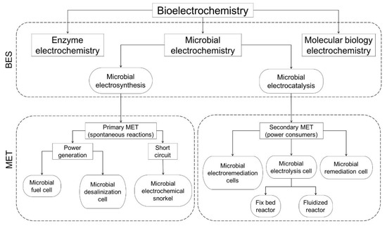
Figure 1.
Diagram illustrating the disciplines of the biochemistry field, the interrelations with bioelectrochemical systems, and their applications as microbial electrochemical technologies.
The first microbial electrochemistry experiences can be tracked back to the first half of the 20th century with the findings by Potter [6] regarding the ability of certain species of bacteria, Escherichia coli, to generate electricity through substrate oxidation processes, followed by the attempts made by Hooker to take advantage of the oxidation–reduction reactions to create an electrical cell [7]. The rapid evolution and interdisciplinary approach have led to the development of different terms to describe their principles and applications. Schröder [1] described the distinction among the concept of microbial electrochemistry, microbial electrocatalysis, and microbial electrosynthesis (Figure 1).
The microbial electrochemistry concept refers to the study and application of interactions between living microbial cells and electrodes through capacitive or Faraday interactions. In capacitive interactions, the changes occur in the double layer capacity of electrodes as result of cell attachment/detachment, when the lipid layer of a microorganism enters in contact, and displaces water molecules and ions from the electrode, resulting in a change of the electrochemical capacity which leads to the flow of electric current. In Faraday interactions, however, oxidation and reduction reactions occur mediated by microbial cells and molecular species involved in extracellular electron transfer. This could be done either by pseudo-capacitive processes (cells and biofilm get charged or uncharged, as a supercapacitor) or by a microbial electrocatalysis process, where the electrochemical reaction is accelerated by microorganisms based on extracellular electron transfer [1].
Microbial electrocatalysis increases the rate of the electrochemical reactions, mediated by microorganisms’ extracellular electron transfer. The electron flow reduces the overpotential or increases the reaction rates at a fixed potential of an electrochemical reaction. Electrocatalysis can be used for substrate degradation as in microbial fuel cells (MFC) allowing, simultaneously, wastewater treatment and energy recovery.
The microbial electrosynthesis concept refers to the production of high-value chemicals through the reduction of carbon dioxide and other organic substrates, mediated by microorganisms able to grow on cathode surfaces. The microorganisms act as catalysts and use the reducing equivalents released from solid-state electrodes as an energy source. Microbial electrosynthesis can be used for producing sodium hydroxide, methane, ethanol, hydrogen and hydrogen peroxide [8,9,10].
The applications of microbial-driven electrochemical processes for production of complex organic compounds, energy generation or environmental solutions are called microbial electrochemical technologies (MET). Depending on the operating conditions, they can be classified as primary or secondary MET. In primary MET, the microbial electrochemical processes (exclusively Faraday processes) either involve extracellular electron transfer (EET) mechanisms directly from cell to acceptor or mediated by electron shuttles. On the other hand, in the secondary MET, the bioelectrochemical processes are controlled by the adjustment of the microbial environmental conditions (pH, oxygen pressure, metabolite concentrations, etc.), as in microbial electrolysis of hydrogen or soil remediation [1]. Roughly, MET can be classified as power producers (electrons derived from oxidized organic matter are conducted to the cathode via external circuit), power consumers (consumption of external power to achieve bioelectrochemical cathodic reactions due to small or negative potential differences not allowing electron flow from anode to cathode) and as intermediate systems that neither produce nor consume power, but require stable electrochemical conditions [5].
According to the application, METs are denominated by different terms (Figure 1) as follows: microbial fuel cells (MFC) for electricity generation; microbial electrolysis cells (MEC) for synthesis of H2 or other compounds through the input of external power to reduce cathode potential; microbial desalination cells (MDC) for water desalination; and microbial remediation cells (MRC) for cathodic reduction of oxidized pollutants like uranium, perchlorate, chlorinated solvents in polluted environments [11,12]. Other MET systems are the microbial electroremediating cells (MERC) that aim at overcoming electron acceptor limitation and maximize the biodegradation of pollutants like the herbicides isoproturon [12], or atrazine [13] in the environment.
Given the potential that MET have for simultaneous wastewater treatment and energy production, different studies have since 2012 explored the technical possibilities and benefits of combining this technology with constructed wetlands (CW). A CW is a biologically engineered wastewater treatment system that relies on the presence of plants and microorganisms, and the interaction of physical, chemical and biological processes, as well as different removal mechanisms [14]. CWs can be classified according to the dominant macrophytes (free-floating, floating leaved, rooted emergent and submerged), hydrology (surface or subsurface flow) and flow direction (horizontal or vertical) [15].
CWs have been extensively investigated, demonstrating their capacity to treat wastewater of different origins such as domestic, industrial, drainage mining, runoff and agriculture effluents [16,17,18,19,20]. CWs are characterized by being a robust and cost-effective technology that requires low operation and maintenance efforts [21,22], and nowadays are used worldwide as a mature solution for decentralized wastewater treatment. However, the major drawback of CW implementation is its area footprint, which is much larger than other compact wastewater treatment technology. To reduce the surface requirements, the CW have, therefore, been evolving from passive to intensified systems, including very recent designs that incorporate the combination of CW with MET [23,24]. Therefore, this paper reviews the principles and the state of the art of MET applied in the field of wastewater treatment with a focus on the potential benefits, challenges and novel setups as result of merging with CW.
2. Microbial Extracellular Electron Transfer (EET)
MET relies on anaerobic environments in aqueous solutions to allow the establishment of synergic consortia between fermentative and bioelectrogenic microorganisms [25,26]. Fermentative microorganisms break down complex organic compounds into simpler structures e.g., acetate, ethanol, glucose, hydrogen gas, aminoacids, polymers (polysaccharides, proteins, and cellulose) and other long-chain, fatty acids, which can easily be oxidized by bioelectrogenic microorganisms [27]. The metabolic characteristics of electroactive microorganisms allow them to obtain energy from electron transfer to a terminal electron acceptor or from an electron donor characterized by being an extracellular conductive and insoluble form. This enables their development in environments where the availability of electron sources or acceptors constitutes a growth limitation [28].
The favorable conditions allow the establishment of microorganism colonies that lead to the formation of electrochemically competent biofilms on solid-state electrodes [4]. It is known that the development of electroactive biofilms enables the electron transfer. However, a complete understanding of the dynamics related to the transfer between electroactive microorganisms and electron acceptors is still under study [29]. EET of bioelectrochemical microorganisms is affected by the potential difference between the final electron carrier and the anode [11,30], and can be executed by two main mechanisms: direct extracellular electron transfer (DEET) and by mediated extracellular electron transfer (MEET).
2.1. Direct Extracellular Electron Transfer (DEET)
DEET requires physical contact between the microorganism and the electrode, usually attached forming a biofilm on the electrode surface. This implies that only bacteria in the first monolayer at the anode surface are electrochemically active [31], which causes a limitation of the catalysis by the maximum cell density in this bacterial monolayer (Figure 2a). However, it has been demonstrated that some species have developed nanowires or pili to reach and utilize distant insoluble electron acceptors or to interconnect inner layers in the biofilm (Figure 2b) [5]. Nanowires (or electroconductive pili) are vesicular extensions of the periplasm and outer membrane of cells (2–3 µm length) designed to facilitate the direct electron transfer between cells and electron acceptors [30,31,32]. The development is a direct response to a limited availability of electron acceptors, making the build-up of thick electroactive layers possible as well as the contact with distant electron acceptors [26,33]. This kind of strategy has been observed in Geobacter and Shewanella species [34,35].
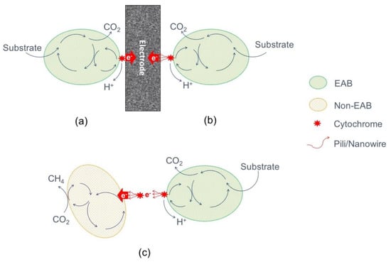
Figure 2.
Simplified representation of extracellular electron transfer mechanisms. Direct extracellular electron transfer (DEET): (a) By membrane-bound cytrochromes, and (b) by electron-conductive pili/nanowires. Direct Interspecies Electron Transfer (DIET) (c).
The ability of microorganisms directly to use other cells as terminal electron acceptors, establishing an electrical contact between two microorganisms, is called direct interspecies electron transfer (DIET) (Figure 2c) [36]. It is an interspecies electron transfer that enables a diversity of microbial communities to gain energy from reactions that no microbe can catalyze [37]. It is a mechanism for exchanging electrons during syntrophic metabolism. Anode biofilms will form electrically conductive aggregates [38]. DIET can also take place with a mineral as mediator, a process in which different species use as conduits of electrons nano-mineral particles or conductive surfaces such as activated carbon granules, coke or biochar [28,39].
2.2. Mediated Extracellular Electron Transfer (MEET)
As alternatives for those bacteria that are neither able to use DEET or DIET have developed metabolic mechanisms mediated by electron shuttles to allow extracellular electron transfer [2] known as MEET. Particular microorganisms, as Escherichia coli, Pseudomonas, Proteus and Bacillus can naturally synthesize and excrete endogenous redox-active molecules that function as electron mediators, such as flavins or phenazine compounds [31,40]. Additionally, these mediators can also be external agents, artificially added to the media or present in natural environments as humic substances [41,42]. In the oxidized form, the mediators can collect electrons either from inside the bacteria cell or from their outer membrane, becoming reduced and subsequently oxidized after transferring electrons to a terminal electron acceptor [30]. Ideally, they should possess good electrochemical reversibility, a positive redox potential to ease the transfer, and without generating any interference in the cellular metabolism [33]. A disadvantage of this mechanism is that the stoichiometry involved in the conversion of electron donors to electricity is not clear. It is also possible that the fermentation processes can continue, leading to methanogenesis processes, hence reducing the electron transfer to the electrodes and consequently affecting the energy generation [26]. Additionally, their use in large-scale MET applications has some inherent limitations such as the necessity of continuous addition, the unstable nature of the compounds, and their potential environmental toxicity [33].
MEET rely on the production of their own secondary metabolites by bacteria (Figure 3) which are low-molecular shuttling compounds like phenazines, pyocyanine, ACNQ (2-amino-3-carboxy-1, 4-naphtho-quinone) and flavins [33,43]. Despite the reuse possibility as an electron carrier, their synthesis are energy costly and will be suitable for closed environments with a minimal substrate replacement as in batch set-ups [26]. However, in the case of dynamic environments like wastewater treatment, those secondary compounds will be exhausted. Some examples of bacteria that are able to produce their own mediators to increase the EET rate are Pseudomonas, Shewanella putrefaciens and Geothrix fermentans [44].
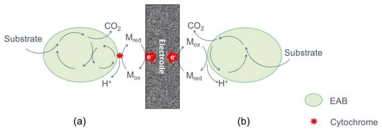
Figure 3.
Simplified representation of mediated extracellular electron transfer (MEET) by secondary metabolites: (a) by outer cell-membrane cytrochromes, and e-shuttles, and (b) by self-produced or external redox mediators.
The MEET process can occur through the anodic reduction of primary metabolites derived of fermentation and anaerobic respiration processes (Figure 4). However, it is not exactly known which kind of reduced products are involved, but the slow reaction rates with electrodes makes it an inefficient electron transfer mechanism [26]. In anaerobic respiration, sulphate reduction leads to the formation of sulfide, which by interactions with available electron acceptors (e.g., iron oxides or electrodes) becomes oxidized, allowing electron transfer [45]. On the other hand, through fermentation processes, it is possible to obtain energy-rich reduced metabolites such as hydrogen, ethanol, formate or ammonia, compounds that can be oxidized by microbial metabolism in the presence of electrocalatytic anodes, thus avoiding the oxidation of those metabolites by other biological processes [43].
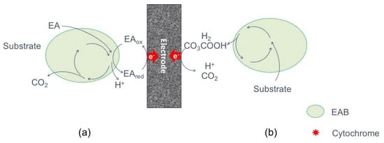
Figure 4.
Simplified representation of MEET by primary metabolites: (a) by reduced terminal electron acceptors (EA), and (b) by oxidation of reduced fermentation products.
3. Electroactive Bacteria and Mixed Biofilms Formation
Electroactive bacteria (EAB) also known as exoelectrogens, electrogens, electricegens, exoelectrogenic or anode respiring bacteria are microorganisms with the ability to conserve energy from electron transfer to an electron acceptor (e.g., a solid-state electrode), and play a key role in the current densities generation and energy efficiency performance of MET [1,46]. EAB have been found in marine/fresh water sediments [47,48,49] as well as in different substrates such as manure [50,51], aerobic/anaerobic wastewater treatment sludge [52,53,54], and wastewater of different origins [55,56].
The presence of EAB in different environments is associated with the inherent characteristics of the electroactive microorganism, most of which are anaerobic or facultative anaerobic, with some species that can endure aerobic conditions [30]. The most extensive studied EAB are from Geobacter and Shewanella genus due to their respiratory versatility for using different carbon sources and electron donors/acceptors [32,57,58,59,60,61]. In previous studies focusing on MET performance, the interaction of a wide variety of microbial communities has been identified, which through DEET processes leads to energy generation [4]. Is understood that as long as there are available substrates in a MET, methanogenic, fermentative and electroactive communities can interact and develop biomass in suspension in the aqueous environment [62] as well as biofilms attached to an electrode [63].
The biofilm formation relies on a self-produced hydrated extracellular polymeric substance composed of polysaccharides, proteins, nucleic acids and lipids. This matrix provides stability, mediates the adhesion of biofilms to surfaces, and allows the interconnection of biofilm cells [64]. Since some EAB are able to develop pili and nanowires [31,32], it is expected that these appendages lead to the establishment of nano-power grids, which enhance biofilm stability, ease the electron transfer at long distances, and contribute to the growth of biofilm thickness, thus increasing the current production [46]. Biofilms play an important role in electrochemical processes and energy production, since higher cell densities allow higher contact among cells enhancing the electron transfer possibilities [65]. In biofilms composed by Geobacter species, long-range electron conductions have been reported from cells located at distances greater than 50 µm with respect to the electrode [66]. However, in biofilms above a thickness threshold of 60 µm, there were no variations in current production due to the minimal current contribution of the outer bacteria [58], derived from the inherent resistance of the biofilm matrix for electron transfer [46].
In MET applications for power harvesting, the mixture of EAB with redox mediator producers, fermentative and methanogenic populations are considered undesirable. Those non-electroactive microorganisms could either release mediators that limit the current flow or could detour electrons through other pathways rather than allowing their use for current generation [67]. However, in environmental applications pure microbial cultures are idyllic due to the complex nature of substances to treat [5]. Mixed populations are highly suitable when a MET will be fed with complex organic matrices like wastewater [8,68,69] since they are able to degrade complex compounds such as carbohydrates and proteins into more simple and suitable structures like volatile fatty acids [30].
Compared with single-strain cultures, the use of mixed-culture bacteria in METs has some advantages like avoiding sterilization, their environmental adaptation, application in continuous processes, higher robustness and electrical productivity [65,68]. In fact, there are reports of current densities (flow of electric charge per electrode surface area) of a MET inoculated with mixed consortia between 516 mA m−2 (anaerobic digester sludge) and 1300 mA m−2 (wastewater), which are higher in comparison with reports of single-strain inoculum with values between 44 mA m−2 (Pseudomona aeroginosa) and 130 mA m−2 (Shewanella oneidensis) [69].
Good sources of mixed cultures are aerobic/anaerobic sludge, sediments, manure and domestic wastewater [30]. In a study using lab-scale MET, the treatment of real wastewater (chemical oxygen demand (COD) = 12,020 +/− mg L−1), has reached a maximal power density (rate of electric energy per electrode surface area) of 204 mW m−2—anode surface [56]. In addition, at the end of operation (day 278th), the microbial composition was characterized by polymerase chain reaction (PCR) techniques and changes were found in the dominant species from 50% to 14% for Actinobacteria, from 17% to 57% for Proteobacteria, and from 33% to 29% for Firmicutes, the Proteobacteria and Firmicutes genus being recognized as EAB [56].
A lab-scale MET inoculated with activated sludge and fed with livestock wastewater (biological oxygen demand—BOD5 = 453 mg L−1) [70], a maximum power density of 197 mW m−2 (cathode area) was found. After 1 month of operation, a microbial characterization of the system was undertaken, finding that the electrodes were dominated by Geobacter species (72%), followed by other EAB belonging to Desulfuromonas (3.1%), Hydrogenophaga (3.1%), Paludibacter (3.1%) and Proteiniphilum (6.3%), all of them bacteria identified before in MFC [70].
4. Microbial Electrochemical Technologies (MET) for Wastewater Treatment
A large potential of energy is kept in wastewaters in the form of biodegradable organic matter. It is known that the energy contained in wastewaters cannot be correlated directly with COD values, but estimations point for 17.7 to 28.7 kJ g−1 COD [71]. In the United States, wastewater treatment facilities consume around 15 GW of power (3% of nationwide power production), whereas 17 GW can be contained in wastewaters of different origins, an amount that could supply the energy requirements for their treatment [27]. MET have shown a potential for wastewater treatment, since their COD removal rates can reach up to 90%, with coulombic efficiencies (fraction of electrons recovered as current versus the maximum possible recovery) higher than 80% [72]. It is estimated that in anaerobic digestion 1 kg COD can be converted to 4.16 kWh of power (1 kWh of usable energy in the form of electricity); therefore, if a MET is intended to compete as an alternative wastewater treatment technology with simultaneous energy generation, it must reach a similar substrate conversion rate [2].
Currently, it is not possible for a MET to produce cost-effective energy [26]. However, it constitutes an alternative technology to harvest energy directly from wastewater [73]. Some of the limitations for field application of METs include: installation costs, expensive electrode materials, and low energy density generated [74]. From the wastewater perspective METs systems arise as an interesting alternative, since they are easily capable of oxidizing degradable organic matter [4]. MET are flexible platforms that by means of oxidation and reduction processes can treat wastewater at a rate of 7.1 kg COD m−3 (reactor volume day−1), and offer the advantage of saving costs like aeration and sludge disposal [75]. However, it is recommended that for high organic loaded/complex wastewater, MET should be complemented with other technologies to obtain fermented products that can be oxidized by electroactive bacteria [5,76].
4.1. Processes and Innovative Setups for Wastewater Treatment
Bioelectrochemical wastewater treatment can be accomplished by electrically coupling a microbial anode to a counter electrode (cathode) that performs a reduction reaction. As a result of this electrical connection between the anode and cathode, the flow of the electrons is promoted [77]. The implementation of METs for wastewater treatment has been based on the different reactions that can be catalyzed by EAB; therefore, the MET operation can be classified as systems based on non-spontaneous reactions and spontaneous reactions.
4.1.1. Non-Spontaneous Reaction Systems
The non-spontaneous reactions occur when the Gibbs free energy of the reaction is positive and the theoretical cell voltage or electromotive force is negative and, therefore, power needs to be supplied. Examples of METs that rely on non-spontaneous reactions are MEC and fluidized systems (Figure 5).
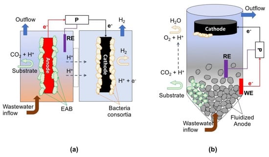
Figure 5.
Examples of microbial electrochemical technology (MET) setups for wastewater treatment. Non-spontaneous reactions: (a) microbial electrolysis cell (MEC) reactor, and (b) fluidized reactor. P = potentionstat; RE = reference electrode; WE = working electrode.
When electrical power is used to enhance the potential difference between the anode and the cathode, either to enable or increase the rate of the electrode reactions, the system is called microbial electrolysis cell (MEC). In a classical MEC, electroactive microorganisms use a solid-state anode as terminal electron acceptor for the oxidation of organic waste substrates to carbon dioxide, while simultaneously releasing protons to the solution. Electrons flow from the anode to the cathode through an external circuit while protons diffuse to the cathode through a proton-exchange membrane separating the two electrode compartments. At the cathode in the presence of a suitable (bio)catalyst, the electrons combine with a soluble electron acceptor, generating a target product [45]. Likewise, electroactive bacteria can also use a cathode as the electron donor for reducing substrates present in the wastewater like NO2, NO3, SO4, C2H2Cl4, among others [78].
To make the cathodic reaction thermodynamically feasible, these reactions require the potential generated from substrate oxidation at the anode to be boosted with an external power supply [45]. The energy can be supplied by a power source or a potentiostat depending on the selected mode of operation: galvanostatic (based on input current flow) or potentiostatic mode (based on a fixed potential between two electrodes). In galvanostatic mode only two electrodes are needed, but if it is wanted to maintain the potential of one of the electrodes under a selected value (working electrode), it is necessary to work with a reference electrode in a 3-electrode configuration. The other electrode is called counter or auxiliary electrode and its potential is dependent upon the current flow circulating through the system. This configuration allows control of the anodic or cathodic reactions, which is crucial for the study of the microbial-electrode interaction.
When the anode potential is controlled in a 3-electrode configuration, the organic matter oxidation is being performed at this working electrode. Some systems have been developed for this purpose, like the classical MEC design, based on 2-chambered configuration and separated by an ion exchange membrane [11]. In other cases, the potential is fixed at the cathode to solve the energy requirements and remove contaminants present in waters by reduction reactions such as SO4 from groundwater [79], and N from low COD effluents [80]. In addition, simpler systems have been developed to allow scaling-up and implementation in wastewater treatment plants. An example of this is a bioelectrochemical denitrification MET system [81]. In these systems, ion exchange membranes and the reference electrode have been removed so that power is supplied through a power source instead of a potentiostat. Bioelectrochemical denitrification presents several advantages compared to classical heterotrophic denitrification; for instance, the unlimited electron source of a cathode (supplied by an electric flux) while avoiding the need for organic matter addition.
Other systems based on non-spontaneous reactions rely on merging a classical fluidized reactor with a MET, like the so-called microbial electrochemical fluidized bed reactor (ME-FBR) [62]. The ME-FBR has been developed to maximize the superficial area of the anode being available for electroactive microorganisms, and improving the kinetics of the catalysis by employing an environment with favorable mixing properties. These systems have been used to treat real wastewater and studies report that the ME-FBR was able to remove up to 95% of the COD in brewery effluent [82].
4.1.2. Spontaneous Reaction Systems
Power Generation Systems
Electric power generation using MFC is the most studied MET application. Organic compounds are oxidized by microorganisms using the anode as electron acceptor. The electrons flow through an external circuit to the cathode where oxygen is reduced [83]. Electrical energy can be recovered from the external circuit because the overall reaction, oxidation of organics and reduction of oxygen are thermodynamically favorable [84].
Generally, MFC configurations are classified as either dual or single chambered designs (Figure 6). In a dual chamber configuration both anode and cathode are immersed in a solution that eases either oxidative or reductive conditions. The protons flow through an ion exchange membrane and the electrons along an external circuit. In a single chamber the anode and the cathode can be immersed on the same electrolyte or the cathode can be exposed to the atmosphere. In this configuration the released protons migrate to the cathode through a polymer electrolyte membrane, and the electrons through an external circuit [30]. Some MFC innovations for wastewater treatment with simultaneous power generation are described below.
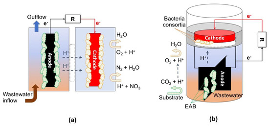
Figure 6.
Examples of set-ups of MET for wastewater treatment. Spontaneous reactions: (a) typical dual-chamber microbial fuel cell (MFC), and (b) single-chamber floating MFC reactor. R = resistor.
Based on the principles of generating conditions for dissolved oxygen gradient by exposing the cathode to the atmosphere, a simple-to-install and operate floating all-in-one MFC system has been proposed [70]. In this system, a floater is fixed to a proton exchange membrane and to a carbon-cloth cathode with Pt catalyst; attached to the same floater by means of a stainless-steel wire either carbon-cloth or carbon-brush anodes are installed, and an external stainless-steel wire and a resistor complete the circuit. Due to its characteristics, this type of system can be operated as a plug-and-play device and installed directly in wastewater pre-treatment units (e.g., settling tanks). The system has the possibility of being scalable and customizable by enlarging the anodes, which will allow the attachment of EAB, thus increasing organic matter consumption. With this type of configuration, it is possible to achieve a removal of BOD and COD up to 63% and 71%, respectively [70].
Efforts in developing innovative shapes and mixture of electrode material to enhance the performance of an MFC lead to the creation of an annular single chamber MFC, or a spiral microbial electrochemical cell [85,86]. This type of MFC reactor is built with a Plexiglas cylindrical chamber with a spiral anode electrode of graphite-varnished stainless-steel mesh, and a cylindrical concentric cathode composed either of a carbon cloth or stainless-steel mesh treated with Pt (0.5 mg cm−2) to enhance the electro-conductive properties of the material. This type of spiral configuration increases the anodic surface area while reducing the space between electrodes. These characteristics led to remarkable results in terms of wastewater treatment, reaching up to 91% of COD removal and a maximal power density of 20 W m−3 (anode working volume) and, given the relative low cost of the implemented materials, it has a potential to be scaled-up.
Another innovative concept with respect to traditional MFC configuration is the so-called tubular MFCs. A variety of this system is a vertical flow reactor composed of two perforated polypropylene tubes, acting as double shell, with an embedded layer of carbon cloth cathode exposed to air, a hydrogel layer acting as intermediate layer and an internal ion exchange membrane. In the interior of this reactor a concentric monolithic-activated carbon anode is installed, and the connection between the anode and cathode is made by an external circuit with a resistor (1000 Ω at starting-up; 150 Ω at normal operative conditions) [87]. In experiments operating two tubular MFC units fed with synthetic wastewater and at different organic loading rates, it was possible to obtain COD removal rates between 51% and 82% with a simultaneous energy production up to 1.75 Wh g−1 COD. These results are promising for scaling-up this reactor in complementary modular systems for polishing effluents from treatment units such as anaerobic digesters [88].
A similar setup called an MFC stack was developed using a PVC pipe as framework modular tubular air-cathode system, divided in different sections conforming independent anodic chambers [89]. Each anodic chamber has perforations on its body; it is wrapped on a layer of carbon fiber cloth containing MnO2, and packed with a cation exchange membrane. Silicone gel tubes hydraulically connect the air-cathode MFC sections, and circuits are composed by titanium wires connecting anode and cathode with an external resistor of 1000 Ω. This modular setup has the advantage of being able to be operated either in series or in parallel circuit mode. With this type of setup, a maximal removal rate of 84% for COD and 91% for NH4 has been reported (at a loading rate of 1.2 Kg COD m3 d−1; maximal power density = 176 W m−2 at 0.38 V and 43 mA). These values indicate potential for treating wastewater with a simultaneous power production.
Short-Circuit Systems
Based on the principles of MET, but in contrast to the traditional MFC approach of simultaneous energy harvesting and pollutant depuration, the microbial electrochemical snorkel (MES) concept was developed [90]. A MES system is a short-circuit-based setup, i.e., not indented to harvest electric current flows and, therefore, its configuration does not require complex electrochemical reactors with ionic exchange membranes or other separators (Figure 7). The design can be simplified to a single piece of conductive material or a full electroconductive granular material bed that creates a direct electrochemical connection between anodic and cathodic zones [91]. A short-circuited system provides the highest currents meaning that it ensures the highest rate for the oxidation of compounds. In the MES, one of the sides of an electrode plays the role of an anode, and the other side the role of a cathode [90]. The anodic part should be exposed to anaerobic conditions and develop an electroactive biofilm over it, while the cathode is exposed to the atmosphere, favoring the creation of redox potential gradient conditions.
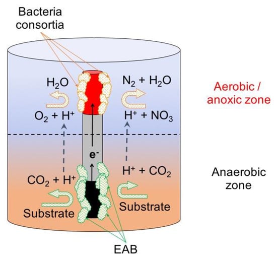
Figure 7.
Example of MET configuration for wastewater treatment: microbial electrochemical snorkel (MES).
Due to the low electrical resistivity of the materials used as snorkels, the electrons are transported from the anodic to the cathodic zone that is characterized by having aerobic/oxic conditions. Here electroactive and facultative bacteria use these electrons for the reduction of oxygen or other available electron acceptors like NO2, NO3, SO4 or S2O3. The concept has been tested in a laboratory scale set-up using glass bioreactors with 120 ml of wastewater (230–600 mg COD L−1), and 20 cm titanium rod (20 cm length) covered with a colonized graphite felt anode in one extreme and a Pt cathode on the other. Operating under batch mode for 4 days, this setup was able to reach a COD removal efficiency of 55% (organic load rate—OLR discharge of 125 mg L−1 d−1) being higher than a similar MFC used as control, showing its potential for wastewater treatment [90].
The use of conductive rods as subsurface snorkels has been investigated to accelerate the anaerobic oxidation of organic matter in marine and freshwater sediments. It has been demonstrated that their introduction in marine sediment promote a change in its redox condition, expressed by the oxidation of the sediments around the snorkels, and its implementation in fresh water has led to the inhibition of methane production after long trial periods [92]. The results suggest that subsurface snorkels could be a sustainable approach for redirecting the microbial respiration in subsurface environments, and profile such systems as a potential alternative for degradation of organic contaminants and inhibition of methanogenesis in that type of environments [92].
The microbial electrochemical snorkels have also been tested for the removal of NO3 from fresh waters in laboratory scale systems. The set-up consisted of a snorkel composed by zero-valent iron rod (25 cm length × 1 cm diameter) with an anodic carbon felt (0.3 cm thick × 7 cm diameter) inserted in a cylindrical reactor of 2 L, seeded with 600 mL of fresh water sediment, and fed with a 2.0 mg L−1 NaNO3 solution. In this setup, the carbon felt eases the attachment of EAB that releases electrons from the consumption of substrates from the anaerobic/anoxic sediment. The electrons flow from the anode to the cathodic section of the rod located on its extreme, where denitrifying bacteria adsorbed in the rod use those electrons for the reduction of NO3 of the overlaying solution. With this setup, operating under batch conditions it was possible to remove up to 98% of NO3 in 16 days [93]. This configuration has also shown its potential to maximize the removal of recalcitrant pollutants, like petroleum hydrocarbons [91].
4.2. Trends on MET for Wastewater Treatment
Interest in MET research has grown since the 1990s, not only for the possibility of power generation and catalysis of useful products, but also for its potential in wastewater treatment. Between 1962 to 2017, 7220 publications dealing with MET were reported (Figure 8). From them, only 34 publications were reported before 1997, but from that year on, the total number of publications increased remarkably to 1055 in 2017.
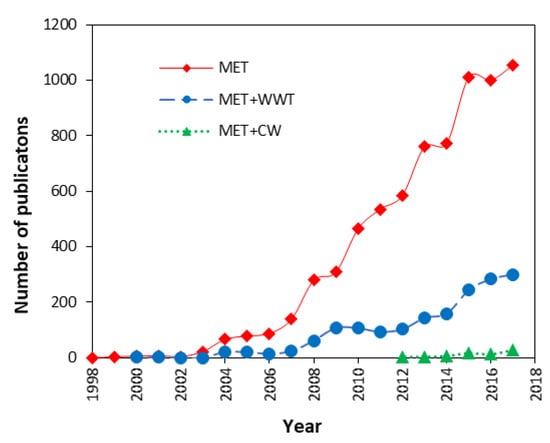
Figure 8.
Trends in publications of METs, their implementation for wastewater treatment (MET+WWT) and their combination with constructed wetlands (MET+CW). Data obtained from Scopus® database. For MET publications, the search was limited to title, abstract and keyword (TITLE-ABS-KEY) using the terms “microbial fuel cell*”, “microbial electrochemical tech*”, “microbial electrochemical sys*”, “bioelectrochemical tech*” and “bioelectrochemical sys*”. For MET+WWT, the search was narrowed adding the terms “wastewater treat*” and “water treat*”. For MET+CW the search was narrowed again, adding the terms “constructed wetlands”, “treatment wetlands”, “engineered wetlands” and “artificial wetlands”. The search included publications in 14 different categories preset by the database: “article”, “conference paper”, “review”, “article in press”, “book chapter”, “note”, “conference review”, “editorial”, “short survey”, “erratum”, “book”, “letter”, “business article” and “undefined”.
The numbers show a rising interest in exploring the potential of MET for power generation or the catalysis of sub products of interest. In terms of wastewater treatment (MET+WWT), the first publication dates-back to 2000, and up to 2017, 1678 peer reviewed works have been published. Regarding the merging of MET and constructed wetlands technology (MET+CW), 73 references were identified showing a growing pattern from 4 publications in 2012 to 28 publications in 2017. In comparison with the total amount of publications related to MET and MET+WWT, the MET+CW are still emerging, but a promising research field as shown by the studies described below.
5. Constructed Wetlands–Microbial Fuel Cell (CW–MFC) Coupling
The presence of redox gradients along a CW depth profile with anaerobic zones at the bottom and anoxic/aerobic zones at the top led to exploration of the possibility of combining them with MET [94]. Similar to a conventional MFC, a CW–MFC includes the installation of an anode located at the bottom in the anaerobic zone, and a cathode located at the top in anoxic/aerobic zone. On the anodic zone, the metabolic activity of electroactive bacteria allows the consumption of organic compounds, releasing electrons that are transferred to the anode. From the anode, the electrons flow along an external circuit to the cathode, where they can be used in the reduction of O2 or NO3. To complete the charge balance, some configurations incorporate an ion separator, others simply allow them to flow in the bulk fluid [24]. Likewise, in conventional MET for wastewater treatment with CW–MFC systems it is indented to achieve a treatment performance at least as good as in conventional CW, but with the added value of harvesting energy derived from EAB metabolic activity and their interaction with the electrodes installed in the set-up [95]. A typical setup of CW–MFC is presented in Figure 9.
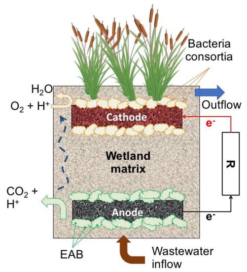
Figure 9.
Typical constructed wetlands–microbial fuel cell (CW–MFC) configuration.
The first experience reported with a CW–MFC was a laboratory-scale reactor for the removal of methylene blue dye, COD and simultaneous power generation from synthetic wastewater (8000 mg L−1) at different dye concentrations [23]. The reactor operated in batch mode for 96 h, and achieved a maximal COD removal of 75% (at 1500 mg L−1 of initial dye concentration), and maximal power density of 15.73 mW m−2, and a maximal current density and 69.75 mA m−2 (at 1000 mg L−1 of initial dye concentration). Since that first study, the potential applications have been expanded from conventional pollutants like organic matter and nutrients to more complicated compounds such as pharmaceuticals. A selection of recent studies published about this merging technology is summarized in Table 1.

Table 1.
Summary of selected studies of merging between constructed wetlands and microbial electrochemical technologies (2016–2018).
In the ambit of conventional pollutants, an alum sludge-based CW–MFC was tested for the removal of organic matter and nutrients, along with electricity production from swine slurry [96]. The test included a laboratory scale set-up operating with a simultaneous up-flow/down-flow feeding pattern, achieving removal efficiencies of 64% of COD, 75% of NH4, 86% for TP, and reaching a maximal power density of 0.268 W m−3. With a CW–MFC up-flow setup, the removal of COD, N was tested, and energy generation from synthetic wastewater, experimenting with different circuit connections, organic loads and electrode configurations [97]. After 1 day of hydraulic retention time (HRT), the average removal efficiencies were 99%, 46% and 96% for COD, NO3 and NH4, respectively, and a maximal power density of 93 mW m−3.
The performance of a laboratory-scale down-flow CW–MFC reactor was tested for nitrate removal and bioenergy generation [98]. The reactor operating in continuous mode with HRT varying from 24 to 96 h, and with a carbon fiber felt working as anode and cathode, reached removal rates around 57% for COD and 80% for NO3 with a maximal power generation of 8.08 mW m−2. A highlighted issue in this work, was the neutral and slightly alkaline environment generated in the reactor operating under closed-circuit configuration. This condition promoted the richness of the bacterial community, increasing the bioenergy generation in comparison with an open-circuit operation with acidic conditions [98].
Regarding the treatment of more complex types of wastewater, the performance of a CW–MFC to treat oil-contaminated wastewater was tested along with electricity generation, and compared with single CW and MFC reactors [99]. The design included a laboratory-scale system operating in an up-flow mode with a HRT of 3 days with a carbon brush as anode and a copper plated carbon-felt as cathode. This CW–MFC reached removal rates close to 95% for oil, 73% for COD and 57% for total organic carbon (TOC) generating a power density of 102 mW m−2. In this study, the plants seem to have an important role in the performance of the cathode, which could be associated to the impact of the roots, which allowed some oxygen transfer to the cathode or the provision of suitable conditions for developing of EAB communities.
The removal of antibiotics (tetracycline and sulfamethoxazole) and the simultaneous electricity generation was tested in an up-flow CW–MFC [100]. In their experiment, laboratory columns operating with HRT of 2.5 days, were fed with synthetic wastewater spiked with different concentrations of tetracycline and sulfamethoxazole (200, 500 and 800 µg L−1), obtaining removal rates above 99.5% for both antibiotics and a maximal power density of 57.8 mW m−2, showing potential as complementary technology for the removal of pharmaceuticals.
The removal of B and the electricity generation were tested with a hybrid CW–MFC, composed of one surface-flow reactor and followed by a horizontal subsurface reactor [101]. The system was operated in a continuous mode fed by 3 pulses per day with synthetic wastewater containing boron in concentrations ranging from 2 to 32 mg L−1. After a stable period of operation, this hybrid system achieved removal rates of B around 63% and a power density generation of 78 mW m−3. Additionally, the removal of NO2 and NO3 was tested with removals of 19% and 47%, respectively. This study also highlighted that the increase in B concentration had a negative impact on the power and current densities generated by the system. Furthermore, enzymes like dehydrogenase and urease were found close to the rhizosphere, which seem to be strongly correlated with the bioelectricity generation in the system, denoting the positive impact of the presence of plants in this type of system.
A recent study tested the degradation of nitrobenzene from wastewater with a single membrane-less CW–MFC compared with the performance of a conventional MFC [102]. This laboratory-scale system was fed with synthetic wastewater containing nitrobenzene (concentrations varying from 5 to 80 mg L−1), with glucose as carbon source (concentration from 100 to 600 mg L−1), and operated under up-flow continuous mode with a HRT of 24 h. The removal rates of nitrobenzene and COD were around 92% and 78%, respectively, promoting a maximal power density of 1.53 mW m−2. This study highlights that the high removal rates of nitrobenzene are the result of an appropriate balance nitrobenzene: COD ratio and HRT (1:16 at HRT = 24 h).
Leaving aside the recovery of energy as an objective, and focusing only on the removal of pollutants, an innovative development has been proposed by using electro-conductive biofilters (instead of external circuits as in the previously tested CW–MFC), resulting in the development of the microbial electrochemical-based constructed wetland (METland). In a METland system, the EAB are stimulated to generate and transfer electrons to an electro-conductive material that act as an unlimited acceptor (Figure 10) maximizing substrate consumption instead of leaving free electrons for methane generation, and consequently to a decrease of microbial metabolism rates (as in an anaerobic system) due to the limited number of electron acceptors [103].
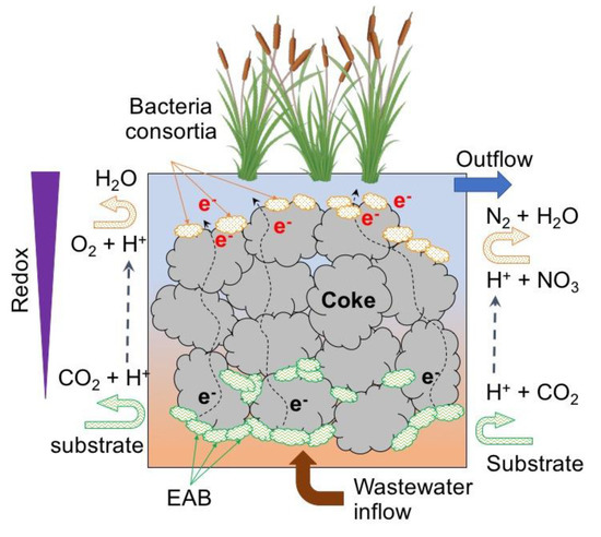
Figure 10.
Conceptual illustration of METland setup.
The METland system has been tested for the removal of organic matter and nitrogen with horizontal subsurface flow (HSSF) coke biofilters at laboratory scale at different hydraulic loading rates (HRT), ranging from 4 to 0.5 days [104]. The coke-based biofilter showed removal rates of 91% for COD and for 96% for BOD5 at the lowest HRT (0.5 d), and 97% for NH4 and 69% for TN at 3.5 d HRT results that suggest that the METland system can enhance biodegradation rates, thus allowing the reduction of the area requirements of classical CWs.
Conceptually, this new system operates similarly to a microbial electrochemical snorkel (MES) [90,91,122], which is composed of a single conductive material that allows the connection between anoxic zones (performing as anode) and oxic zones (performing as cathode). Like the CW–MFC technology, the METland technology is still in development and, therefore, several uncertainties exist regarding the dynamics involved in the removal of pollutants, and in its performance over time.
6. Challenges and Future Perspectives for CW–MFC Systems
Based on the studies that merge CW and MFC, it is possible to identify that most of the reported systems have been designed and operated at laboratory scale, and their implementation as a suitable real-scale system is still in development. The main challenges for scaling up the CW–MFC technology are the same as those facing traditional MET for wastewater treatment. This constraint includes the electrolyte resistance (ohmic), the charge-transfer resistance due to slow reaction rates on electrodes (kinetic), and the resistance caused by retarded diffusion (transport) [123]. These limitations result in low power densities, and coulombic efficiencies that range between 9 to 72 mW m−2 and 0.05–10.48% [111].
Additional limiting factors that must be considered include i) the internal resistance of a CW–MFC, which increases linearly as the size and distance between electrodes increase [24]; ii) the over-potential during activation and the insufficient electrical contact between bacteria and anode [124]; iii) competition among EAB and other microorganisms (e.g., methanogenic bacteria) for electrons or substrates leading to low coulombic efficiencies [111]; iv) the deterioration of the cathode over time, and the excessive growth of heterotrophic bacteria around it that make the concentrations of electron acceptors like O2 plummet [116]; as well as v) the high concentration of organic matter that could slightly increase the acidity inside the systems, limiting the growth of EAB and the diffusion of protons, and therefore affecting the coulombic efficiency [115].
The constraints are also associated to the design of the circuits, and the inherent limitations of membranes and electrode materials to allow the flow of ions and electrons in the system [125]. Therefore, efforts must be invested in the understanding of the processes involved in the release, transfer and acceptance of electrons, and in minimizing the losses [126]. Additional efforts must be invested in determining optimal inoculums, substrate conditions, ionic strength of water, internal and external resistance of the systems, as well as innovative electrode spacing between them [124]; all with the aim of designing and developing cost-effective electrodes and circuits. Based on the reviewed publications of CW–MFC, it can be identified that the research priorities have a strong preference in terms of power generation enhancement. However, up to now, the energy yields of the tested systems are not competitive in comparison with other alternatives such a biogas collection from conventional wastewater treatment facilities. That fact also constrains the ambition of scaling up the CW–MFC systems.
An approach that seems to be underestimated as a research field is the study and development of setups based on the merging of CW and MET that do not target the harvesting of energy, but rely on the explained bioelectrochemcial principles to enhance the performance of CW. One option worth investigating would be the merging of CW and MEC or MRC, which by setting potentials through an external power supply, makes it possible to control the inner conditions of the system, allowing the lack of electron acceptors to be overcome, and therefore leading to the maximization of treatment efficiency. Another alternative approach would be the study of CW–MET setups that dispense with electrodes and external circuits but use electro-conductive materials and operate in short-circuit mode. The proposed alternatives could lead to the enhancement of removal processes inside the CW, leading to a reduction of the required area to build a CW, and therefore diminishing the footprint of the system.
7. Conclusions
Microbial electrochemical technologies constitute a relatively recent innovative approach for wastewater treatment where a laboratory-scale level shows remarkable results in terms of the removal of organic matter and other pollutants of interest, as well as for the recovery of potential energy store in chemical form in wastewaters.
Among the alternative MET configurations, CW–MFC is one of the most innovative setups, which merges the groundbreaking approach of MFC, and the well-known capabilities of constructed wetlands for wastewater treatment. This combination constitutes an interesting and promising setup among the different options of constructed wetland technology, especially for the possibilities of using this setup as a new option of intensified wetland systems that could keep a high performance with a lower footprint.
However, there are still several challenges that must be overcome for scaling-up the technology, if it is expected to develop a setup being able to compete with other wastewater treatment alternatives in terms of recovery energy, e.g., in the form of biogas. These efforts should be a focus in the study and development of new materials, internal conditions of the systems, inoculums, and configuration of systems, as well as increasing the understanding of the different processes involved in the release, transfer and use of electrons in these systems.
It is of interest to invest efforts in systems that take advantage of bioelectrochemical principles without simultaneous power generation. An option for this would be to invest higher efforts on the research of CW operating with MEC or MERC setups, systems operating in short-circuit mode like snorkel-based METs, or in innovative MET–CW setups such as METland systems.
Author Contributions
Writing-Original Draft Preparation, C.A.R.-V.; Writing-Review and Editing, A.P., C.A.A., P.N.C., A.E.-N., H.B.
Funding
This study has been supported with resources of the project “iMETland: A new generation of Microbial Electrochemical Wetland for effective decentralized wastewater treatment systems”, funded by the European Union’s Horizon 2020 research and innovation program (grant agreement No. 642190).
Acknowledgments
C.A.R.-V. kindly acknowledges to the Administrative Department of Science and Technology of Colombia (COLCIENCIAS) for granting his PhD scholarship (conv. 646/2014).
Conflicts of Interest
The authors declare no conflict of interest.
References
- Schröder, U.; Harnisch, F.; Angenent, L.T. Microbial electrochemistry and technology: Terminology and classification. Energy Environ. Sci. 2015, 8, 513–519. [Google Scholar] [CrossRef]
- Arends, J.B.A.; Verstraete, W. 100 Years of Microbial Electricity Production: Three Concepts for the Future. Microb. Biotechnol. 2012, 5, 333–346. [Google Scholar] [CrossRef] [PubMed]
- Sharma, M.; Bajracharya, S.; Gildemyn, S.; Patil, S.A.; Alvarez-Gallego, Y.; Pant, D.; Rabaey, K.; Dominguez-Benetton, X. A critical revisit of the key parameters used to describe microbial electrochemical systems. Electrochim. Acta 2014, 140, 191–208. [Google Scholar] [CrossRef]
- Rabaey, K.; Rodríguez, J.; Blackall, L.L.; Keller, J.; Gross, P.; Batstone, D.; Verstraete, W.; Nealson, K.H. Microbial ecology meets electrochemistry: Electricity-driven and driving communities. ISME J. 2007, 1, 9–18. [Google Scholar] [CrossRef] [PubMed]
- Rosenbaum, M.; Franks, A. Microbial catalysis in bioelectrochemical technologies: Status quo, challenges and perspectives. Appl. Microbiol. Biotechnol. 2014, 98, 509–518. [Google Scholar] [CrossRef] [PubMed]
- Potter, M. Electrical effects accompanying the decomposition of organic compounds. Proc. R. Soc. Lond. B 1911, 84, 260–276. [Google Scholar] [CrossRef]
- Hooker, S.B. Thirty-fourth Annual Meeting of the Society of American Bacteriologists. J. Bacteriol. 1933, 25, 19–21. [Google Scholar]
- Desloover, J.; Arends, J.B.A.; Hennebel, T.; Rabaey, K. Operational and technical considerations for microbial electrosynthesis. Biochem. Soc. Trans. 2012, 40, 1233–1238. [Google Scholar] [CrossRef] [PubMed]
- Pant, D.; Singh, A.; Van Bogaert, G.; Irving Olsen, S.; Singh Nigam, P.; Diels, L.; Vanbroekhoven, K. Bioelectrochemical systems (BES) for sustainable energy production and product recovery from organic wastes and industrial wastewaters. RSC Adv. 2012, 2, 1248–1263. [Google Scholar] [CrossRef]
- Patil, S.A.; Arends, J.B.A.; Vanwonterghem, I.; van Meerbergen, J.; Guo, K.; Tyson, G.W.; Rabaey, K. Selective Enrichment Establishes a Stable Performing Community for Microbial Electrosynthesis of Acetate from CO2. Environ. Sci. Technol. 2015, 49, 8833–8843. [Google Scholar] [CrossRef] [PubMed]
- Borjas, Z.; Ortiz, J.; Aldaz, A.; Feliu, J.; Esteve-Núñez, A. Strategies for Reducing the Start-up Operation of Microbial Electrochemical Treatments of Urban Wastewater. Energies 2015, 8, 14064–14077. [Google Scholar] [CrossRef]
- Quejigo, J.R.; Domínguez-Garay, A.; Dörfler, U.; Schroll, R.; Esteve-Núñez, A. Anodic shifting of the microbial community profile to enhance oxidative metabolism in soil. Soil Biol. Biochem. 2018, 116, 131–138. [Google Scholar] [CrossRef]
- Domínguez-Garay, A.; Esteve-Núñez, A. Designing strategies for operating Microbial Electrochemical Systems to clean up polluted soils under non-flooded conditions. Bioelectrochemistry 2018, 124, 142–148. [Google Scholar] [CrossRef] [PubMed]
- Kadlec, R.; Wallace, S. Treatment Wetlands, 2nd ed.; CRC Press: Boca Raton, FL, USA, 2009; ISBN 9781420012514. [Google Scholar]
- Vymazal, J. Constructed wetlands for wastewater treatment. Water 2010, 2, 530–549. [Google Scholar] [CrossRef]
- Reed, S.C.; Crites, R.W.; Middlebrooks, E.J. Natural Systems for Waste Management and Treatment, 2nd ed.; McGraw-Hill, Inc.: New York, NY, USA, 1995. [Google Scholar]
- Paredes, D.; Vélez, M.E.; Kuschk, P.; Mueller, R.A. Effects of type of flow, plants and addition of organic carbon in the removal of zinc and chromium in small-scale model wetlands. Water Sci. Technol. 2007, 56, 199–205. [Google Scholar] [CrossRef] [PubMed]
- Ghobrial, M.G. Pigments and moisture contents in Phragmites australis (Cav.) Trin. Ex Steudel, would be engines for monitoring biodegradation of petroleum contaminants in constructed wetlands. Aust. J. Basic Appl. Sci. 2008, 2, 1068–1075. [Google Scholar]
- Nivala, J.; Wallace, S.; Headley, T.; Kassa, K.; Brix, H.; van Afferden, M.; Müller, R. Oxygen transfer and consumption in subsurface flow treatment wetlands. Ecol. Eng. 2012, 61, 544–554. [Google Scholar] [CrossRef]
- Vymazal, J. Constructed wetlands for treatment of industrial wastewaters: A review. Ecol. Eng. 2014, 73, 724–751. [Google Scholar] [CrossRef]
- Brix, H.; Koottatep, T.; Laugesen, C.H. Wastewater treatment in tsunami affected areas of Thailand by constructed wetlands. Water Sci. Technol. 2007, 56, 69–74. [Google Scholar] [CrossRef] [PubMed]
- Vymazal, J. The use constructed wetlands with horizontal sub-surface flow for various types of wastewater. Ecol. Eng. 2009, 35, 1–17. [Google Scholar] [CrossRef]
- Yadav, A.K.; Dash, P.; Mohanty, A.; Abbassi, R.; Mishra, B.K. Performance assessment of innovative constructed wetland-microbial fuel cell for electricity production and dye removal. Ecol. Eng. 2012, 47, 126–131. [Google Scholar] [CrossRef]
- Doherty, L.; Zhao, Y.; Zhao, X.; Hu, Y.; Hao, X.; Xu, L.; Liu, R. A review of a recently emerged technology: Constructed wetland – microbial fuel cells. Water Resour. 2015, 85, 38–45. [Google Scholar] [CrossRef] [PubMed]
- Reimers, C.E.; Tender, L.M.; Fertig, S.; Wang, W. Harvesting energy from the marine sediment—Water interface. Environ. Sci. Technol. 2001, 35, 192–195. [Google Scholar] [CrossRef] [PubMed]
- Lovley, D.R. Bug juice: Harvesting electricity with microorganisms. Nat. Rev. Microbiol. 2006, 4, 497–508. [Google Scholar] [CrossRef] [PubMed]
- Logan, B.E.; Rabaey, K. Conversion of wastes into bioelectricity and chemicals by using microbial electrochemical technologies. Science 2012, 337, 686–690. [Google Scholar] [CrossRef] [PubMed]
- Kato, S. Biotechnological aspects of microbial extracellular electron transfer. Microbes Environ. 2015, 30, 133–139. [Google Scholar] [CrossRef] [PubMed]
- Bonanni, P.S.; Schrott, G.D.; Busalmen, J.P. A long way to the electrode: How do Geobacter cells transport their electrons? Biochem. Soc. Trans. 2012, 40, 1274–1279. [Google Scholar] [CrossRef] [PubMed]
- Butti, S.K.; Velvizhi, G.; Sulonen, M.L.K.; Haavisto, J.M.; Oguz Koroglu, E.; Yusuf Cetinkaya, A.; Singh, S.; Arya, D.; Annie Modestra, J.; Vamsi Krishna, K.; et al. Microbial electrochemical technologies with the perspective of harnessing bioenergy: Maneuvering towards upscaling. Renew. Sustain. Energy Rev. 2016, 53, 462–476. [Google Scholar] [CrossRef]
- Mao, L.; Verwoerd, W.S. Selection of organisms for systems biology study of microbial electricity generation: A review. Int. J. Energy Environ. Eng. 2013, 4, 17. [Google Scholar] [CrossRef]
- Kracke, F.; Vassilev, I.; Krömer, J.O. Microbial electron transport and energy conservation—The foundation for optimizing bioelectrochemical systems. Front. Microbiol. 2015, 6, 1–18. [Google Scholar] [CrossRef] [PubMed]
- Patil, S.A.; Hägerhäll, C.; Gorton, L. Electron transfer mechanisms between microorganisms and electrodes in bioelectrochemical systems. Bioanal. Rev. 2012, 4, 159–192. [Google Scholar] [CrossRef]
- Reguera, G.; McCarthy, K.D.; Mehta, T.; Nicoll, J.S.; Tuominen, M.T.; Lovley, D.R. Extracellular electron transfer via microbial nanowires. Nature 2005, 435, 1098–1101. [Google Scholar] [CrossRef] [PubMed]
- Gorby, Y.A.; Yanina, S.; McLean, J.S.; Rosso, K.M.; Moyles, D.; Dohnalkova, A.; Beveridge, T.J.; Chang, I.S.; Kim, B.H.; Kim, K.S.; et al. Electrically conductive bacterial nanowires produced by Shewanella oneidensis strain MR-1 and other microorganisms. Proc. Natl. Acad. Sci. USA 2006, 103, 11358–11363. [Google Scholar] [CrossRef] [PubMed]
- Summers, Z.M.; Fogarty, H.E.; Leang, C.; Franks, A.E.; Malvankar, N.S.; Lovley, D.R. Direct exchange of electrons within aggregates of an evolved syntrophic coculture of anaerobic bacteria. Science 2010, 330, 1413–1415. [Google Scholar] [CrossRef] [PubMed]
- Shrestha, P.M.; Rotaru, A.E. Plugging in or going wireless: Strategies for interspecies electron transfer. Front. Microbiol. 2014, 5, 1–8. [Google Scholar] [CrossRef] [PubMed]
- Malvankar, N.S.; Lau, J.; Nevin, K.; Franks, A.E.; Tuominen, M.T.; Lovley, D.R. Electrical conductivity in a mixed-species biofilm. Appl. Environ. Microbiol. 2012, 78, 5967–5971. [Google Scholar] [CrossRef] [PubMed]
- Liu, F.; Rotaru, A.-E.; Shrestha, P.M.; Malvankar, N.S.; Nevin, K.P.; Lovley, D.R. Promoting direct interspecies electron transfer with activated carbon. Energy Environ. Sci. 2012, 5, 8982–8989. [Google Scholar] [CrossRef]
- Erable, B.; Duţeanu, N.; Ghangrekar, M.; Dumas, C.; Scott, K. Application of electro-active biofilms. Biofouling 2010, 26, 57–71. [Google Scholar] [CrossRef] [PubMed]
- Voordeckers, J.W.; Kim, B.C.; Izallalen, M.; Lovley, D.R. Role of geobacter sulfurreducens outer surface c-type cytochromes in reduction of soil humic acid and anthraquinone-2, 6-disulfonate. Appl. Environ. Microbiol. 2010, 76, 2371–2375. [Google Scholar] [CrossRef] [PubMed]
- Kotloski, N.J.; Gralnick, J.A. Flavin electron shuttles dominate extracellular electron transfer by Shewanella oneidensis. MBio 2013, 4, 10–13. [Google Scholar] [CrossRef] [PubMed]
- Schröder, U. Anodic electron transfer mechanisms in microbial fuel cells and their energy efficiency. Phys. Chem. Chem. Phys. 2007, 9, 2619–2629. [Google Scholar] [CrossRef] [PubMed]
- Hernandez, M.E.; Kappler, A.; Newman, D.K. Phenazines and other redox-active antibiotics promote microbial mineral reduction. Appl. Environ. Microbiol. 2004, 70, 921–928. [Google Scholar] [CrossRef] [PubMed]
- Rabaey, K.; Rozendal, R.A. Microbial electrosynthesis—revisiting the electrical route for microbial production. Nat. Rev. Microbiol. 2010, 8, 706–716. [Google Scholar] [CrossRef] [PubMed]
- Borole, A.P.; Reguera, G.; Ringeisen, B.; Wang, Z.-W.; Feng, Y.; Kim, B.H. Electroactive biofilms: Current status and future research needs. Energy Environ. Sci. 2011, 4, 4813–4834. [Google Scholar] [CrossRef]
- Lovley, D.R. Extracellular electron transfer: Wires, capacitors, iron lungs, and more. Geobiology 2008, 6, 225–231. [Google Scholar] [CrossRef] [PubMed]
- Sajana, T.K.; Ghangrekar, M.M.; Mitra, A. Application of sediment microbial fuel cell for in situ reclamation of aquaculture pond water quality. Aquac. Eng. 2013, 57, 101–107. [Google Scholar] [CrossRef]
- Risgaard-Petersen, N.; Damgaard, L.R.; Revil, A.; Nielsen, L.P. Mapping electron sources and sinks in a marine biogeobattery. J. Geophys. Res. Biogeosci. 2014, 119, 1475–1486. [Google Scholar] [CrossRef]
- Min, B.; Kim, J.; Oh, S.; Regan, J.M.; Logan, B.E. Electricity generation from swine wastewater using microbial fuel cells. Water Resour. 2005, 39, 4961–4968. [Google Scholar] [CrossRef] [PubMed]
- Vilajeliu-Pons, A.; Puig, S.; Pous, N.; Salcedo-Dávila, I.; Bañeras, L.; Balaguer, M.D.; Colprim, J. Microbiome characterization of MFCs used for the treatment of swine manure. J. Hazard. Mater. 2015, 288, 60–68. [Google Scholar] [CrossRef] [PubMed]
- Villano, M.; Aulenta, F.; Beccari, M.; Majone, M. Start-up and performance of an activated sludge bioanode in microbial electrolysis cells. Chem. Eng. Trans. 2012, 27, 109–114. [Google Scholar] [CrossRef]
- Lobato, J.; Cañizares, P.; Fernández, F.J.; Rodrigo, M.A. An evaluation of aerobic and anaerobic sludges as start-up material for microbial fuel cell systems. New Biotechnol. 2012, 29, 415–420. [Google Scholar] [CrossRef] [PubMed]
- Gao, C.; Wang, A.; Wu, W.-M.; Yin, Y.; Zhao, Y.-G. Enrichment of anodic biofilm inoculated with anaerobic or aerobic sludge in single chambered air-cathode microbial fuel cells. Bioresour. Technol. 2014, 167, 124–132. [Google Scholar] [CrossRef] [PubMed]
- Escapa, A.; San-Martín, M.I.; Morán, A. Potential Use of Microbial Electrolysis Cells in Domestic Wastewater Treatment Plants for Energy Recovery. Front. Energy Res. 2014, 2, 1–10. [Google Scholar] [CrossRef]
- Velvizhi, G.; Venkata Mohan, S. Bioelectrogenic role of anoxic microbial anode in the treatment of chemical wastewater: Microbial dynamics with bioelectro-characterization. Water Resour. 2015, 70, 52–63. [Google Scholar] [CrossRef] [PubMed]
- Arends, J.B.A.; Blondeel, E.; Tennison, S.R.; Boon, N.; Verstraete, W. Suitability of granular carbon as an anode material for sediment microbial fuel cells. J. Soils Sediments 2012, 12, 1197–1206. [Google Scholar] [CrossRef]
- Bonanni, P.S.; Bradley, D.F.; Schrott, G.D.; Busalmen, J.P. Limitations for current production in Geobacter sulfurreducens biofilms. ChemSusChem 2013, 6, 711–720. [Google Scholar] [CrossRef] [PubMed]
- Sydow, A.; Krieg, T.; Mayer, F.; Schrader, J.; Holtmann, D. Electroactive bacteria—Molecular mechanisms and genetic tools. Appl. Microbiol. Biotechnol. 2014, 98, 8481–8495. [Google Scholar] [CrossRef] [PubMed]
- Schrott, G.D.; Bonanni, P.S.; Robuschi, L.; Esteve-Nuñez, A.; Busalmen, J.P. Electrochemical insight into the mechanism of electron transport in biofilms of Geobacter sulfurreducens. Electrochim. Acta 2011, 56, 10791–10795. [Google Scholar] [CrossRef]
- Estevez-Canales, M.; Kuzume, A.; Borjas, Z.; Füeg, M.; Lovley, D.; Wandlowski, T.; Esteve-Núñez, A. A severe reduction in the cytochrome C content of Geobacter sulfurreducens eliminates its capacity for extracellular electron transfer. Environ. Microbiol. Rep. 2015, 7, 219–226. [Google Scholar] [CrossRef] [PubMed]
- Tejedor-Sanz, S.; Quejigo, J.R.; Berná, A.; Esteve-Núñez, A. The planktonic relationship between fluid-like electrodes and bacteria: Wiring in motion. ChemSusChem 2017, 10, 693–700. [Google Scholar] [CrossRef] [PubMed]
- Picioreanu, C.; van Loosdrecht, M.C.M.; Katuri, K.P.; Scott, K.; Head, I.M. Mathematical model for microbial fuel cells with anodic biofilms and anaerobic digestion. Water Sci. Technol. 2008, 57, 965–971. [Google Scholar] [CrossRef] [PubMed]
- Flemming, H.; Wingender, J. The biofilm matrix. Nat. Rev. Microbiol. 2010, 8, 623–633. [Google Scholar] [CrossRef] [PubMed]
- Yang, S.; Du, F.; Liu, H. Characterization of mixed-culture biofilms established in microbial fuel cells. Biomass Bioenergy 2012, 46, 531–537. [Google Scholar] [CrossRef]
- Franks, A.E.; Glaven, R.H.; Lovley, D.R. Real-time spatial gene expression analysis within current-producing biofilms. ChemSusChem 2012, 5, 1092–1098. [Google Scholar] [CrossRef] [PubMed]
- Commault, A.S.; Lear, G.; Weld, R.J. Maintenance of Geobacter-dominated biofilms in microbial fuel cells treating synthetic wastewater. Bioelectrochemistry 2015, 106, 150–158. [Google Scholar] [CrossRef] [PubMed]
- Zhang, Y.C.; Jiang, Z.H.; Liu, Y. Application of electrochemically active bacteria as anodic biocatalyst in microbial fuel cells. Chin. J. Anal. Chem. 2015, 43, 155–163. [Google Scholar] [CrossRef]
- Nevin, K.; Richter, H.; Covalla, S.F.; Johnson, J.P.; Woodard, T.L.; Orloff, A.L.; Jia, H.; Zhang, M.; Lovley, D.R. Power output and columbic efficiencies from biofilms of Geobacter sulfurreducens comparable to mixed community microbial fuel cells. Environ. Microbiol. 2008, 10, 2505–2514. [Google Scholar] [CrossRef] [PubMed]
- Yamashita, T.; Ishida, M.; Ogino, A.; Yokoyama, H. Evaluation of organic matter removal and electricity generation by using integrated microbial fuel cells for wastewater treatment. Environ. Technol. 2016, 37, 228–236. [Google Scholar] [CrossRef] [PubMed]
- Heidrich, E.S.; Curtis, T.P.; Dolfing, J. Determination of the internal chemical energy of wastewater. Environ. Sci. Technol. 2011, 45, 827–832. [Google Scholar] [CrossRef] [PubMed]
- Rahimnejad, M.; Adhami, A.; Darvari, S.; Zirepour, A.; Oh, S.-E. Microbial fuel cell as new technology for bioelectricity generation: A review. Alexandria Eng. J. 2015, 54, 745–756. [Google Scholar] [CrossRef]
- Corbella, C.; Guivernau, M.; Viñas, M.; Puigagut, J. Operational, design and microbial aspects related to power production with microbial fuel cells implemented in constructed wetlands. Water Resour. 2015, 84, 232–242. [Google Scholar] [CrossRef] [PubMed]
- Zhang, Q.; Hu, J.; Lee, D.-J. Microbial fuel cells as pollutant treatment units: Research updates. Bioresour. Technol. 2016, 217, 121–128. [Google Scholar] [CrossRef] [PubMed]
- Wang, H.; Ren, Z.J. A comprehensive review of microbial electrochemical systems as a platform technology. Biotechnol. Adv. 2013, 31, 1796–1807. [Google Scholar] [CrossRef] [PubMed]
- Rosenbaum, M.; Agler, M.T.; Fornero, J.J.; Venkataraman, A.; Angenent, L.T. Integrating BES in the wastewater and sludge treatment line. In Bioelectrochemical Systems: From Extracellular Electron Transfer to Biotechnological Application; IWA Publishing: London, UK, 2010; pp. 393–408. ISBN 9781843392330. [Google Scholar]
- Rozendal, R.A.; Hamelers, H.V.M.; Rabaey, K.; Keller, J.; Buisman, C.J.N. Towards practical implementation of bioelectrochemical wastewater treatment. Trends Biotechnol. 2008, 26, 450–459. [Google Scholar] [CrossRef] [PubMed]
- Clauwaert, P.; Rabaey, K.; Aelterman, P.; De Schamphelaire, L.; Pham, T.H.; Boeckx, P.; Boon, N.; Verstraete, W. Biological denitrification in microbial fuel cells. Environ. Sci. Technol. 2007, 41, 3354–3360. [Google Scholar] [CrossRef] [PubMed]
- Coma, M.; Puig, S.; Pous, N.; Balaguer, M.D.; Colprim, J. Biocatalysed sulphate removal in a BES cathode. Bioresour. Technol. 2013, 130, 218–223. [Google Scholar] [CrossRef] [PubMed]
- Tong, Y.; He, Z. Nitrate removal from groundwater driven by electricity generation and heterotrophic denitrification in a bioelectrochemical system. J. Hazard. Mater. 2013, 262, 614–619. [Google Scholar] [CrossRef] [PubMed]
- Tejedor-Sanz, S.; de Gregoris, T.B.; Salas, J.J.; Pastor, L.; Esteve-Núñez, A. Integrating a microbial electrochemical system into a classical wastewater treatment configuration for removing nitrogen from low COD effluents. Environ. Sci. Water Res. Technol. 2016, 2, 884–893. [Google Scholar] [CrossRef]
- Tejedor-Sanz, S.; Fernández-Labrador, P.; Hart, S.; Torres, C.I.; Esteve-Núñez, A. Geobacter dominates the inner layers of a stratified biofilm on a fluidized anode during brewery wastewater treatment. Front. Microbiol. 2018, 9, 1–12. [Google Scholar] [CrossRef] [PubMed]
- Logan, B.E.; Hamelers, B.; Rozendal, R.; Schröder, U.; Keller, J.; Freguia, S.; Aelterman, P.; Verstraete, W.; Rabaey, K. Microbial fuel cells: Methodology and technology. Environ. Sci. Technol. 2006, 40, 5181–5192. [Google Scholar] [CrossRef] [PubMed]
- Modin, O.; Gustavsson, D.J.I. Opportunities for microbial electrochemistry in municipal wastewater treatment—An overview. Water Sci. Technol. 2014, 69, 1359–1372. [Google Scholar] [CrossRef] [PubMed]
- Mardanpour, M.M.; Esfahany, M.N.; Behzad, T.; Sedaqatvand, R. Single chamber microbial fuel cell with spiral anode for dairy wastewater treatment. Biosens. Bioelectron. 2012, 38, 264–269. [Google Scholar] [CrossRef] [PubMed]
- Naraghi, Z.G.; Yaghmaei, S.; Mardanpour, M.M.; Hasany, M. Produced water treatment with simultaneous bioenergy production using novel bioelectrochemical systems. Electrochim. Acta 2015, 180, 535–544. [Google Scholar] [CrossRef]
- Kim, J.R.; Premier, G.C.; Hawkes, F.R.; Dinsdale, R.M.; Guwy, A.J. Development of a tubular microbial fuel cell (MFC) employing a membrane electrode assembly cathode. J. Power Sources 2009, 187, 393–399. [Google Scholar] [CrossRef]
- Kim, J.R.; Premier, G.C.; Hawkes, F.R.; Rodríguez, J.; Dinsdale, R.M.; Guwy, A.J. Modular tubular microbial fuel cells for energy recovery during sucrose wastewater treatment at low organic loading rate. Bioresour. Technol. 2010, 101, 1190–1198. [Google Scholar] [CrossRef] [PubMed]
- Zhuang, L.; Zheng, Y.; Zhou, S.; Yuan, Y.; Yuan, H.; Chen, Y. Scalable microbial fuel cell (MFC) stack for continuous real wastewater treatment. Bioresour. Technol. 2012, 106, 82–88. [Google Scholar] [CrossRef] [PubMed]
- Erable, B.; Etcheverry, L.; Bergel, A. From microbial fuel cell (MFC) to microbial electrochemical snorkel (MES): Maximizing chemical oxygen demand (COD) removal from wastewater. Biofouling 2011, 27, 319–326. [Google Scholar] [CrossRef] [PubMed]
- Cruz-Viggi, C.; Presta, E.; Bellagamba, M.; Kaciulis, S.; Balijepalli, S.K.; Zanaroli, G.; Petrangeli Papini, M.; Rossetti, S.; Aulenta, F. The “Oil-Spill Snorkel”: An innovative bioelectrochemical approach to accelerate hydrocarbons biodegradation in marine sediments. Front. Microbiol. 2015, 6, 1–11. [Google Scholar] [CrossRef] [PubMed]
- Nevin, K.; Izbicki, J.; Snoeyenbos-West, O.; Lovley, D. Shifting microbial respiration patterns in soils and sediments with benthic snorkels. In Proceedings of the 14th International Symposium on Microbial Ecology—The Power of the Small, Copenhagen, Denmark, 20 August 2014; p. 25. [Google Scholar]
- Yang, Q.; Zhao, H.; Liang, H. Denitrification of overlying water by microbial electrochemical snorkel. Bioresour. Technol. 2015, 197, 512–514. [Google Scholar] [CrossRef] [PubMed]
- Corbella, C.; Garfí, M.; Puigagut, J. Vertical redox profiles in treatment wetlands as function of hydraulic regime and macrophytes presence: Surveying the optimal scenario for microbial fuel cell implementation. Sci. Total Environ. 2014, 470–471, 754–758. [Google Scholar] [CrossRef] [PubMed]
- Dotro, G.; Molle, P.; Nivala, J.; Puigagut, J.; Stein, O. Treatment Wetlands, 1st ed.; IWA Publishing: London, UK, 2017; ISBN 9781780408767. [Google Scholar]
- Doherty, L.; Zhao, Y.; Zhao, X.; Wang, W. Nutrient and organics removal from swine slurry with simultaneous electricity generation in an alum sludge-based constructed wetland incorporating microbial fuel cell technology. Chem. Eng. J. 2015, 266, 74–81. [Google Scholar] [CrossRef]
- Oon, Y.L.; Ong, S.A.; Ho, L.N.; Wong, Y.S.; Dahalan, F.A.; Oon, Y.S.; Lehl, H.K.; Thung, W.E. Synergistic effect of up-flow constructed wetland and microbial fuel cell for simultaneous wastewater treatment and energy recovery. Bioresour. Technol. 2016, 203, 190–197. [Google Scholar] [CrossRef] [PubMed]
- Wang, J.; Song, X.; Wang, Y.; Abayneh, B.; Li, Y.; Yan, D.; Bai, J. Nitrate removal and bioenergy production in constructed wetland coupled with microbial fuel cell: Establishment of electrochemically active bacteria community on anode. Bioresour. Technol. 2016, 221, 358–365. [Google Scholar] [CrossRef] [PubMed]
- Yang, Q.; Wu, Z.; Liu, L.; Zhang, F.; Liang, S. Treatment of oil wastewater and electricity generation by integrating constructed wetland with microbial fuel cell. Materials 2016, 9, 885. [Google Scholar] [CrossRef] [PubMed]
- Zhang, S.; Song, H.L.; Yang, X.L.; Yang, Y.L.; Yang, K.Y.; Wang, X.Y. Fate of tetracycline and sulfamethoxazole and their corresponding resistance genes in microbial fuel cell coupled constructed wetlands. RSC Adv. 2016, 6, 95999–96005. [Google Scholar] [CrossRef]
- Türker, O.C.; Yakar, A. A hybrid constructed wetland combined with microbial fuel cell for boron (B) removal and bioelectric production. Ecol. Eng. 2017, 102, 411–421. [Google Scholar] [CrossRef]
- Xie, T.; Jing, Z.; Hu, J.; Yuan, P.; Liu, Y.; Cao, S. Degradation of nitrobenzene-containing wastewater by a microbial-fuel-cell-coupled constructed wetland. Ecol. Eng. 2018, 112, 65–71. [Google Scholar] [CrossRef]
- Esteve-Núñez, A. Electricity-generating Bacteria. Bioelectrogenesis: Sustainable Biotechnology. 2015. Available online: http://www.bioelectrogenesis.com/docs/Abraham_Esteve Nunez_Intl_Innovation_181_Research_Media_04.pdf (accessed on 23 August 2018).
- Aguirre-Sierra, A.; Bacchetti De Gregoris, T.; Berná, A.; Salas, J.J.; Aragón, C.; Esteve-Núñez, A. Microbial electrochemical systems outperform fixed-bed biofilters for cleaning-up urban wastewater. Environ. Sci. Water Res. Technol. 2016, 2, 4435–4448. [Google Scholar] [CrossRef]
- Corbella, C.; Garfí, M.; Puigagut, J. Long-term assessment of best cathode position to maximise microbial fuel cell performance in horizontal subsurface flow constructed wetlands. Sci. Total Environ. 2016, 563–564, 448–455. [Google Scholar] [CrossRef] [PubMed]
- Fang, Z.; Song, H.; Yu, R.; Li, X. A microbial fuel cell-coupled constructed wetland promotes degradation of azo dye decolorization products. Ecol. Eng. 2016, 94, 455–463. [Google Scholar] [CrossRef]
- Li, T.; Fang, Z.; Yu, R.; Cao, X.; Song, H.; Li, X. The performance of the microbial fuel cell-coupled constructed wetland system and the influence of the anode bacterial community. Environ. Technol. 2016, 37, 1683–1692. [Google Scholar] [CrossRef] [PubMed]
- Xu, L.; Zhao, Y.; Doherty, L.; Hu, Y.; Hao, X. Promoting the bio-cathode formation of a constructed wetland-microbial fuel cell by using powder activated carbon modified alum sludge in anode chamber. Sci. Rep. 2016, 6, 1–9. [Google Scholar] [CrossRef] [PubMed]
- Xu, D.; Xiao, E.R.; Xu, P.; Zhou, Y.; Zhou, Q.H.; Xu, D.; Wu, Z.B. Effects of Influent Organic Loading Rates and Electrode Locations on the Electrogenesis Capacity of Constructed Wetland-Microbial Fuel Cell Systems. Environ. Prog. Sustain. Energy 2017, 36, 435–441. [Google Scholar] [CrossRef]
- Fang, Z.; Cheng, S.; Cao, X.; Wang, H.; Li, X. Effects of electrode gap and wastewater condition on the performance of microbial fuel cell coupled constructed wetland. Environ. Technol. 2017, 38, 1051–1060. [Google Scholar] [CrossRef] [PubMed]
- Liu, S.; Feng, X.; Li, X. Bioelectrochemical approach for control of methane emission from wetlands. Bioresour. Technol. 2017, 241, 812–820. [Google Scholar] [CrossRef] [PubMed]
- Song, H.; Zhang, S.; Long, X.; Yang, X.; Li, H.; Xiang, W. Optimization of bioelectricity generation in constructed wetland-coupled microbial fuel cell systems. Water 2017, 9, 185. [Google Scholar] [CrossRef]
- Srivastava, P.; Dwivedi, S.; Kumar, N.; Abbassi, R.; Garaniya, V.; Yadav, A.K. Performance assessment of aeration and radial oxygen loss assisted cathode based integrated constructed wetland-microbial fuel cell systems. Bioresour. Technol. 2017, 244, 1178–1182. [Google Scholar] [CrossRef] [PubMed]
- Wang, J.; Song, X.; Wang, Y.; Bai, J.; Bai, H.; Yan, D.; Cao, Y.; Li, Y.; Yu, Z.; Dong, G. Bioelectricity generation, contaminant removal and bacterial community distribution as affected by substrate material size and aquatic macrophyte in constructed wetland-microbial fuel cell. Bioresour. Technol. 2017, 245, 372–378. [Google Scholar] [CrossRef] [PubMed]
- Wang, J.; Song, X.; Wang, Y.; Zhao, Z.; Wang, B.; Yan, D. Effects of electrode material and substrate concentration on the bioenergy output and wastewater treatment in air-cathode microbial fuel cell integrating with constructed wetland. Ecol. Eng. 2017, 99, 191–198. [Google Scholar] [CrossRef]
- Xu, L.; Zhao, Y.; Wang, T.; Liu, R.; Gao, F. Energy capture and nutrients removal enhancement through a stacked constructed wetland incorporated with microbial fuel cell. Water Sci. Technol. 2017, 76, 28–34. [Google Scholar] [CrossRef] [PubMed]
- Xu, L.; Zhao, Y.; Tang, C.; Doherty, L. Influence of glass wool as separator on bioelectricity generation in a constructed wetland-microbial fuel cell. J. Environ. Manag. 2018, 207, 116–123. [Google Scholar] [CrossRef] [PubMed]
- Yakar, A.; Türe, C.; Türker, O.C.; Vymazal, J.; Saz, Ç. Impacts of various filtration media on wastewater treatment and bioelectric production in up-flow constructed wetland combined with microbial fuel cell (UCW-MFC). Ecol. Eng. 2018, 117, 120–132. [Google Scholar] [CrossRef]
- Xu, F.; Cao, F.; Kong, Q.; Zhou, L.; Yuan, Q.; Zhu, Y.; Wang, Q.; Du, Y.; Wang, Z. Electricity production and evolution of microbial community in the constructed wetland-microbial fuel cell. Chem. Eng. J. 2018, 339, 479–486. [Google Scholar] [CrossRef]
- Shen, X.; Zhang, J.; Liu, D.; Hu, Z.; Liu, H. Enhance performance of microbial fuel cell coupled surface flow constructed wetland by using submerged plants and enclosed anodes. Chem. Eng. J. 2018, 351, 312–318. [Google Scholar] [CrossRef]
- Saz, Ç.; Türe, C.; Türker, O.C.; Yakar, A. Effect of vegetation type on treatment performance and bioelectric production of constructed wetland modules combined with microbial fuel cell (CW-MFC) treating synthetic wastewater. Environ. Sci. Pollut. Res. 2018, 25, 8777–8792. [Google Scholar] [CrossRef] [PubMed]
- Yang, Y.; Guo, J.; Sun, G.; Xu, M. Characterizing the snorkeling respiration and growth of Shewanella decolorationis S12. Bioresour. Technol. 2013, 128, 472–478. [Google Scholar] [CrossRef] [PubMed]
- He, Z.; Minteer, S.D.; Angenent, L.T. Electricity generation from artificial wastewater using an upflow microbial fuel cell. Environ. Sci. Technol. 2005, 39, 5262–5267. [Google Scholar] [CrossRef] [PubMed]
- Nitisoravut, R.; Regmi, R. Plant microbial fuel cells: A promising biosystems engineering. Renew. Sustain. Energy Rev. 2017, 76, 81–89. [Google Scholar] [CrossRef]
- Logan, B.E.; Wallack, M.J.; Kim, K.Y.; He, W.; Feng, Y.; Saikaly, P.E. Assessment of Microbial Fuel Cell Configurations and Power Densities. Environ. Sci. Technol. Lett. 2015, 2, 206–214. [Google Scholar] [CrossRef]
- Gude, V.G. Wastewater treatment in microbial fuel cells—An overview. J. Clean. Prod. 2016, 122, 287–307. [Google Scholar] [CrossRef]
© 2018 by the authors. Licensee MDPI, Basel, Switzerland. This article is an open access article distributed under the terms and conditions of the Creative Commons Attribution (CC BY) license (http://creativecommons.org/licenses/by/4.0/).