1. Introduction
Reverse osmosis (RO) is a successful water purification method that uses a semipermeable membrane to eliminate organic and nonorganic pollutants from treated water. Compared to nanofiltration (NF) and ultrafiltration (UF), RO technology has the smallest pores and is the most energy intensive. In the context of water desalination, RO is extensively employed to eliminate a wide range of pollutants including salt, bacteria, viruses, and other minerals from seawater and brackish water and produces high-quality potable water [
1]. The RO process is also deployed in several fields of wastewater treatment process, as it is distinguished by several merits that make it a superior technique for removing a wide range of toxic compounds and producing safe water [
2,
3]. Indeed, the RO process can achieve a high rejection rate and produce treated water that fulfils demanding quality requirements. Municipal and industrial effluents can all be effectively treated with RO technology. The capacity to retrofit present treatment plants with RO technology or integrate RO technology into new processes in hybrid systems is made possible due to the compact design of RO units, which also permits for installation in smaller spaces. Consequently, the RO process is well-matched for small-, medium-, and large-scale applications, as it can be effortlessly scaled following the required capacity. The RO process consumes a lower amount of energy per unit of treated water than other treatment technologies, such as thermal desalination systems [
4]. Nevertheless, there are a few drawbacks to the RO process that should be tackled in future investigations. For example, membrane scaling and fouling, which occur when particles, organic debris, and scale build up on the membrane surface, are the most alarming causes of impaired performance and call for systematic cleaning or membrane replacement [
5,
6]. Furthermore, RO introduces several issues when it comes to the elimination of emerging and micro-pollutants from industrial effluents [
7,
8]. Low rejection rates are deduced as being due to the capacity of some emergent contaminants, such as hormone-disrupting substances and insecticides, to penetrate through the membrane’s pores [
9]. However, the selection of a suitable membrane with a smaller pore size can enhance the rejection rate and sustain a high level of water recovery. Moreover, advanced oxidation approaches can be used with RO to eliminate (oxidize) these pollutants before they reach the membrane [
10]. On top of this, the RO process consumes a lot of energy, especially when many high-pressure pumps are necessary. The overall operational costs can also be amplified due to the necessity of schedule maintenance and membrane replacement, due to fouling and scaling problems [
11,
12]. However, integrating energy recovery equipment, such as pressure exchangers and energy-efficient pumps, can resolve the issue of the high energy consumption of RO systems [
13,
14].
The current investigation intends to improve the effectiveness of the entire RO treatment for the elimination of toxic pollutants from wastewater, by examining the hydrodynamics of the feed spacer in a spiral wound module of the RO process. The hydrodynamics of the feed spacer must be thoroughly investigated in order to improve the overall performance, as the fouling propensity and associated water flux are substantially affected by the hydrodynamics of the feed spacer. The feed spacer is an imperative part to guarantee uniform flow distribution across the membrane area. The porous feed spacer is precisely positioned in the module and placed between two envelopes, facing the active layer of each envelope. Indeed, the feed spacer serves as a supportive net that holds the two neighbouring envelopes apart, allowing feed water to travel vertically across the membrane’s active layer [
15]. Undoubtedly, the concentration polarization happens when solutes build up on the membrane surface, which results in less effectual mass transfer operation. Accordingly, the design and configuration of the feed spacer should be optimized while considering the aspects of hydrodynamics [
16,
17]. The concentration polarization can be mitigated through an optimal feed spacer design that endorses uniform flow, moderates stagnant areas, and increases mass transfer across the membrane [
18,
19]. The following exhibits some examples of related studies that deal with investigating the hydrodynamic-based feed spacers of the RO process.
Gu et al. (2017) [
20] evaluated the impacts of feed spacer geometry on concentration polarization using three-dimensional computational fluid dynamics (CFD) simulations. The results of numerical simulation showed that a fully woven spacer attained the lowest concentration polarization. Also, the fully woven spacer with a mesh angle of 60° guaranteed the highest water flux. In this regard, the spacer with a 90° mesh angle introduced the lowest pressure drop.
Considering the water desalination RO process, Singh et al. (2022) [
19] analysed the simultaneous impacts of different spacer filament geometries, angle of attack, and Reynolds number on the performance metrics of a RO membrane module, comprising water flux, solute flux, and pressure drop. The authors used a three-dimensional CFD model to conduct their study. The findings showed that the lowermost solute flux (and therefore the lowest concentration polarization) could be attained by using triangular spacer filament. Moreover, the orientation of the feed spacer impacted the pressure drop per unit length, while the triangular spacer filament had the greatest pressure drop.
To observe the significance of mitigating the energy loss of the spiral wound module of RO-based water desalination, Guan et al. (2023) [
21] evaluated the consequences of several filament diameter ratios and the spacer mesh angle on the energy loss and mass transfer coefficient in a spiral wound RO module. The outcomes ascertained the substantial effect of the spacer geometry, as the pressure drop increased with an increasing space mesh angle. Furthermore, it was guaranteed that the lessening of pressure dropped by about 58%, due to the dropping of the filament diameter ratio from 1.0 to 0.45.
Despite the previous studies being concerned about the improvement and geometric features of the feed spacer in a spiral wound module and analysing how feed spacers can impact the rejection efficiency and water recovery metrics of RO process-based water desalination in particular, analysing the hydrodynamics of a feed spacer and the removal of a pollutant from wastewater has not been achieved yet. In this regard, Al-Obaidi (2023) [
22] developed a specific model to measure the efficacy of a spiral wound module in the RO process concerning the removal of contaminants from wastewater, which was reinforced by utilising the correlations of Schock and Miquel (1987) [
23] and Da Costa et al. (1994) [
24] to characterise the pressure drop throughout the feed side of the module. Al-Obaidi (2023) [
22] used this model to explore the performance of sixteen various feed spacers concerning the removal of dimethylphenol from wastewater, considering a constant set of inlet conditions. Despite the outcomes of this study, which identified the most successful feed spacers, the specific influences of variable characteristics of feed spacers, including the height of the feed spacer, the angle of the filaments, and porosity, on the hydrodynamic of RO-based dimethylphenol removal from wastewater was not covered in [
22]. In other words, there is a necessity to explore the hydrodynamics and interrelationship between the characteristics of feed spacers and the removal of dimethylphenol from wastewater. The current study attempts to close the gap in the literature by utilising the model developed by the same author (Al-Obaidi, 2023 [
22]) to conduct thorough simulations, using constant values of operational conditions, while considering the feed spacer type UF−3 (as a case study), inside a spiral wound module of the RO process, throughout the removal of dimethylphenol from wastewater. Specifically, the simulation will be carried out to evaluate the influences of feed spacer characteristics (i.e., the height of the type UF−3 feed spacer, the angle of flow diversion of the feed spacer, and the porosity) on the mass transfer coefficient, pressure drop, friction factor, axial flow velocity, water flux, specific energy consumption, and dimethylphenol rejection. However, it should be noted that the present study focuses on the removal of dimethylphenol from wastewater with an inlet concentration of 6.548 × 10
−3 kmol/m
3 (799.97 ppm). Thus, it is fair to admit the negligible influence of membrane fouling, due to low inlet concentration, compared to the case of seawater desalination (30,000–50,000 ppm). Indeed, the consequences of the studied spacer characteristics on mass transfer coefficient, pressure drop, and cross flow velocity would reflect the concentration polarization in this process. Expectedly, this study introduces a comprehensive understanding of the behaviours of hydrodynamic parameters in the feed channel for variable angles of flow diversion of the UF−3 feed spacer and elaborates on the associated dimethylphenol removal and water recovery. Accordingly, the associated findings of this study are advantageous in designing efficient and cost-effective spiral wound modules, which in turn aid in improving the performance metrics of the RO process concerning the removal of toxic compounds from wastewater.
4. Simulation of a Spiral Wound Module Containing a UF−3 Feed Spacer
Considering the inlet conditions of 6.548 × 10⁻³ kmol/m3, 3 × 10⁻³ m3/s, 15 atm, and 31.5 °C for dimethylphenol concentration, pump pressure, and water temperature, respectively, the simulation results of the actual design of a spiral wound module containing a UF−3 feed spacer identified 98.81%, 14.65%, and 3.6 kWh/m3 as the dimethylphenol rejection, water recovery, and specific energy consumption, respectively.
The following simulation would investigate the impact of variable design parameters of a UF−3 feed spacer on the hydrodynamics and performance metrics of a single spiral wound module of the RO process working at the same set of operating conditions (mentioned above) and undertaking dimethylphenol removal from wastewater. Accordingly, the impacts of the variables, namely the height of the feed spacer, the angle of the filaments, and the porosity on the hydrodynamics and performance indicators of the module will be investigated. The hydrodynamics and performance indicators under consideration are the pressure drop throughout the feed channel (Equation (12) of
Table 1), friction factor (Equation (22) of
Table 1), axial fluid velocity (Equation (23) of
Table 1), mass transfer coefficient (Equation (4) of
Table 1), water flux through the membrane pores (Equation (1) of
Table 1), dimethylphenol rejection levels (Equation (17) of
Table 1), water recovery levels (Equation (18) of
Table 1), and specific energy consumption (Equation (25) of
Table 1).
4.1. Effects of Feed Spacer Height
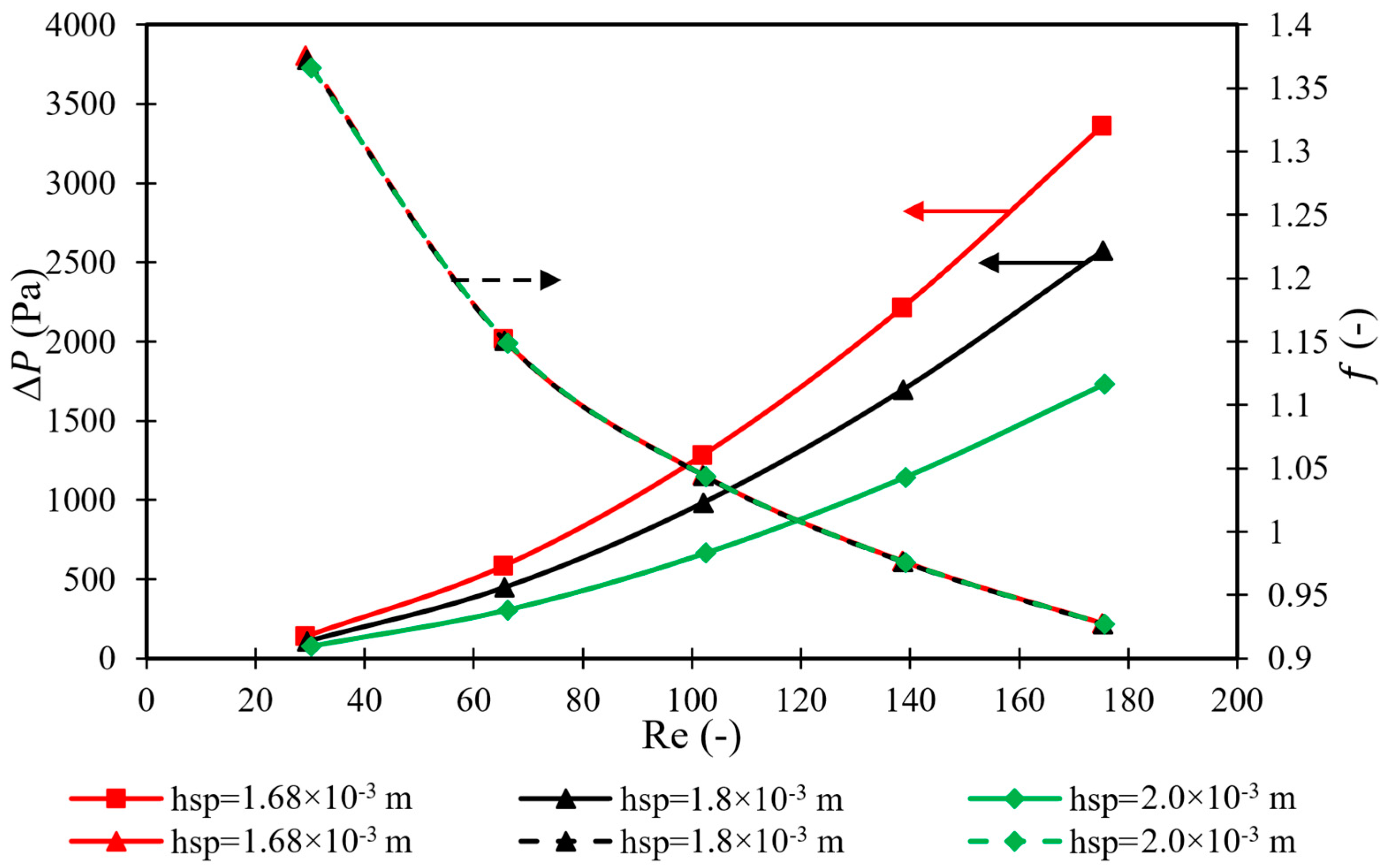
Figure 2 shows the relationship between the pressure drop and friction factor, against the increase in Reynolds number, for the UF−3 feed spacer at different feed spacer heights and a constant filament angle of 135°. The increase in Reynolds number can explain the growth of feed flow rate from 1 × 10
−3 to 5 × 10
−3 m
3/s, with a step change of 1 × 10
−3 m
3/s. In the laminar flow domain (characterised by a low Reynolds number), a clear reduction in the friction factor (more than 32%) can be seen in
Figure 2, as a result of increasing the Reynolds number from 30 to 175, which fits the reverse relationship of Equation (22). However, the increase in feed spacer height, which implies increasing the distance between the membrane layers from 1.68 × 10
−3 m to 2 × 10
−3 m, has an inconsiderable impact on the friction factor. In other words, the results of
Figure 2 indicate somewhat similar values of friction factor for the three tested feed spacer heights during the variation in the Reynolds number between 30 and 175.
An increase in the height of the feed spacer from 1.68 × 10
−3 m to 2 × 10
−3 m significantly reduces the pressure drop throughout the membrane feed channel. In this regard, it should be noted that lower pressure drops would lead to a lower concentration polarization [
26]. To professionally analyse this result, it can be said that a smoother feed solution flow (with less resistance) is likely made possible by increasing the feed spacer height, which creates more open spaces between the membrane layers. There is less of a pressure drop throughout the module as a result of the decreased flow resistance. This implies that an improvement in fluid dynamics can be achieved by a higher spacer height, which lowers resistance to water flow through the membrane at a lower pressure drop. In this aspect, it is important to realise that the consequence of increasing the height of the feed spacer is a lower mass transfer coefficient in the feed channel. Indeed, the altered flow patterns within the module, caused by increasing the feed spacer height, could be the reason for the reduced mass transfer coefficient. A larger spacer height can result in less turbulence and less direct contact between the membrane surface and the feed solution, even though it further enhances flow distribution. As a result, there may be less efficient mass transport of solutes across the membrane and a higher concentration polarization rate. In turn, this would lead to a higher solute flux and a lower rate of solute rejection (
Figure 3). Thus, it is recommended to utilise the lowest height of the feed spacer, to guarantee the highest dimethylphenol rejection. Due to the highest level of turbulence with the lowest height of the feed spacer, the solute accumulation would be at a lower level, which signifies the growth of water permeation through the membrane pores (increased water recovery) (
Figure 3).
Figure 4 shows the importance of using a smaller feed spacer height, as it introduces the lowest specific energy consumption, due to having the uppermost water permeation at a lower concentration polarization. This is already commensurate with increasing the mass transfer coefficient, as an important key to mitigate the accumulation of dimethylphenol on the membrane surface, which improves the water flux and reduces the solute flux throughout the membrane pores. Thus, the utilisation of a smaller feed spacer would be a fantastic option for the exclusion of dimethylphenol from wastewater, since it enhances the mass transfer coefficient.
Beyond this point, the UF−3 feed spacer is originally designed with a height of 1.68 × 10⁻³ m, and, therefore, it can be said that this is the optimum value of feed spacer height, as it resulted in the lowest specific energy consumption, highest water recovery levels, lowest concentration polarization, and the highest dimethylphenol rejection levels. Despite the argument of a possible higher degree of fouling when using a lower feed spacer height, it can be claimed that the elimination of dimethylphenol from wastewater occurs at a very low concentration, which would not influence the overall RO performance.
In summary, it is obvious that maintaining the actual height of the UF−3 feed spacer of 1.68 × 10⁻³ m offers advantages in securing the highest rate of turbulence, which enhances the mass transfer coefficient and improves the dimethylphenol rejection levels, water recovery levels, and the specific energy consumption. Furthermore, it is vital to highlight the interrelationship between the resistance to water flow through the membrane and the specific energy consumption. In this aspect, an increase in the feed spacer height would lower the pressure drop, which means a lower resistance to water flow through the membrane. However, increasing the feed spacer height results in a higher specific energy consumption. This is attributed to less water permeation at higher feed spacer heights, due to a reduction in turbulence intensity.
4.2. Effects of the Angle of the Filaments
Considering the design parameters of the UF−3 feed spacer (
Table 2) and using parameters of 6.548 × 10
−3 kmol/m
3, 3 × 10
−3 m
3/s, 15 atm, and 31.5 °C for dimethylphenol concentration, flow rate, pressure, and temperature, respectively,
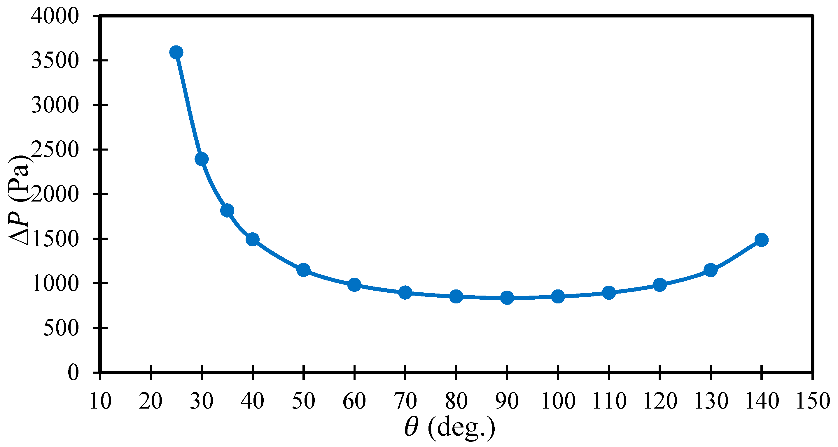
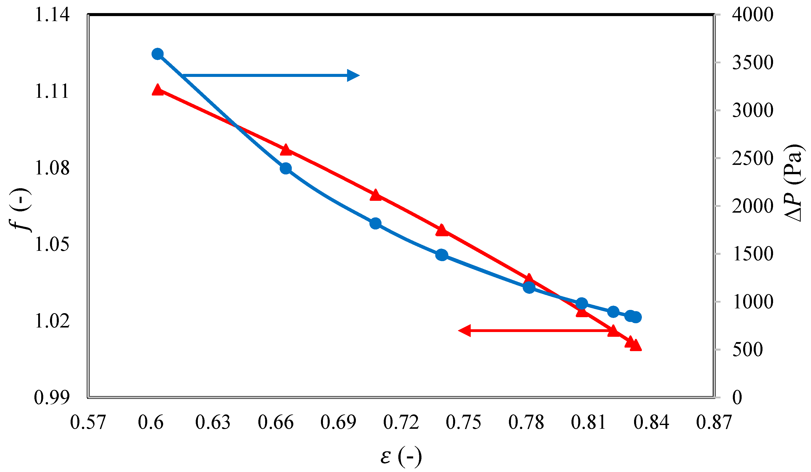
Figure 5 shows that an increase in the angle between the filaments up to 90°, at a fixed operating feed flow rate, causes a significant reduction in pressure drop along the feed channel, which then clearly decreases after 90°. In this regard, Gu et al. (2017) [
20] identified that the lowest pressure drop occurs with a mesh angle of 90°. This is due to a continuous reduction in axial velocity at the membrane surface with a progressive concentration polarization (i.e., a decrease in the shear stress) as the angle increases up to 90° (
Figure 6), which is readily associated with a decreasing mass transfer coefficient (
Figure 6). However, any additional increase in the angle between the filaments (beyond 90°) causes a rise in pressure drop as the axial velocity increases. Therefore, it is fair to admit that the optimum value of the hydrodynamic angle, namely 90°, results in the lowest pressure drop (
Figure 5). Referring to
Figure 5 and
Figure 6, this corresponds to having the lowest axial velocity (5.37 cm/s) and the minimum mass transfer coefficient (4.08 × 10
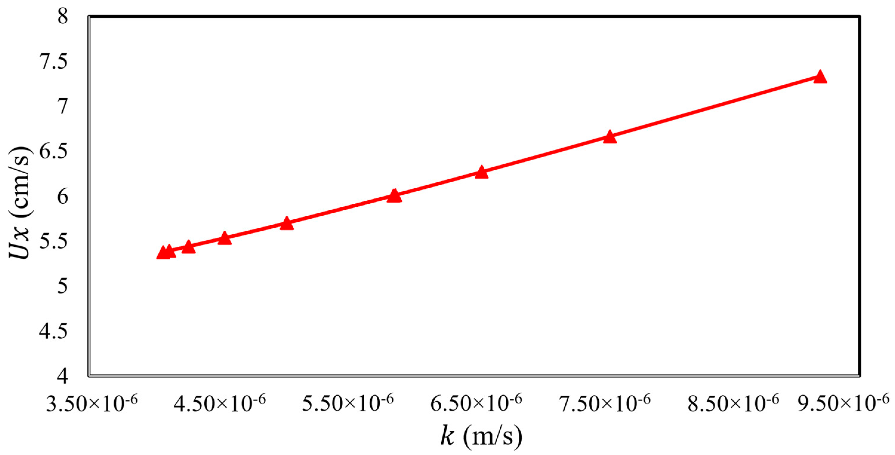
−6). Indeed, increasing the axial velocity definitely increases the mass transfer coefficient (
Figure 7). Undoubtedly, higher axial velocity would reduce concentration polarization by sweeping away the concentrated boundary layer that forms on the membrane surface [
27].
In this regard, it should be noted that the mass transfer coefficient and dimethylphenol rejection, or the membrane’s effectiveness in blocking the solute flow, are positively correlated. Higher mass transfer coefficients and lower concentration polarization are frequently associated with higher solute rejection, due to less solute accumulation on the membrane surface, resulting in fewer opportunities for solute passage through the membrane.
Thus, it can be said that the maximum mass transfer coefficient implies the maximum level of rejection of dimethylphenol, which is another important performance indicator of the RO process. However, the penalty for increasing the mass transfer coefficient is an increase in the pressure drop throughout the feed channel.
To systematically discuss dimethylphenol rejection at different angles of filaments,
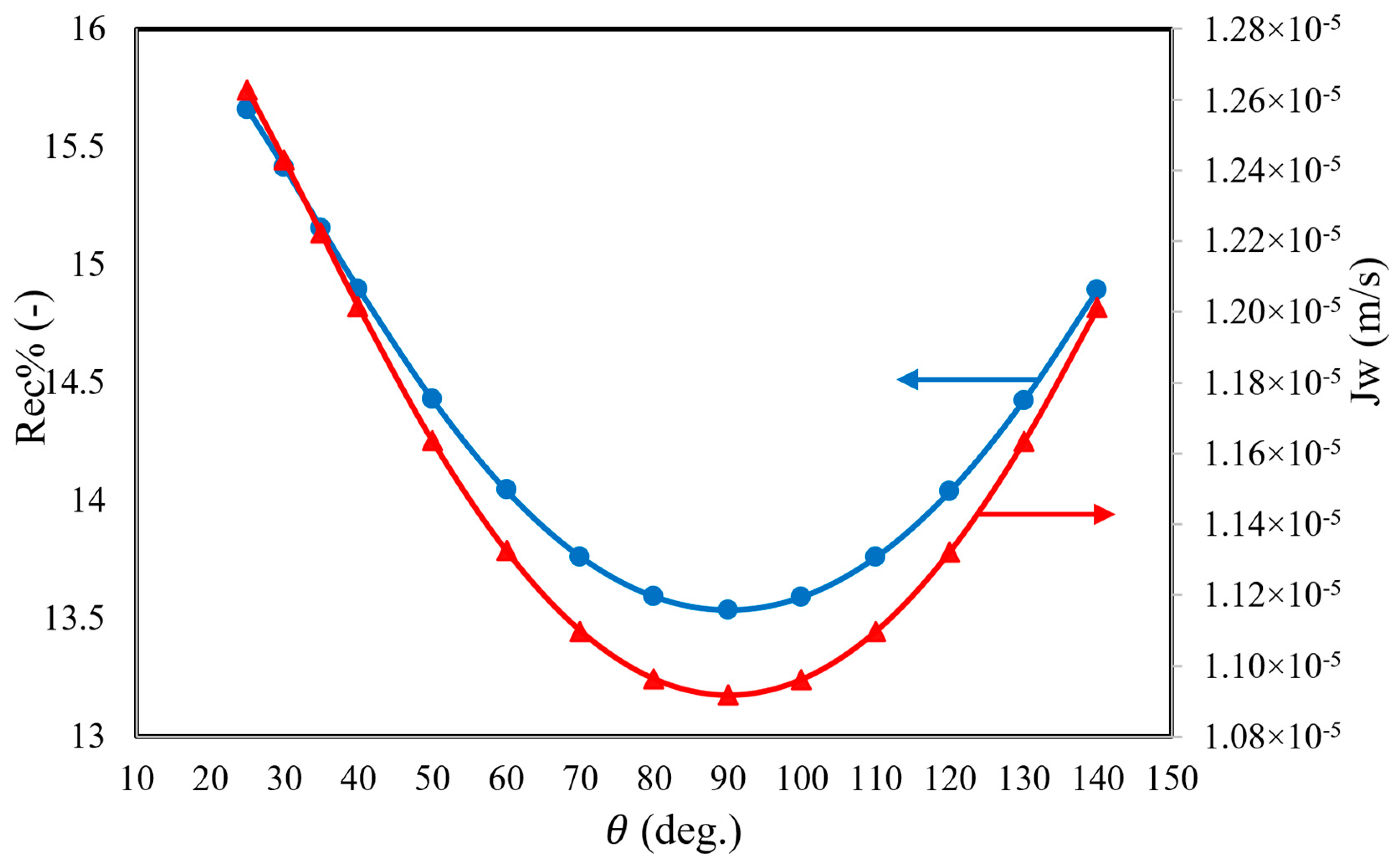
Figure 8 indicates that an increase in the filament angle up to 90° resulted in a reduction in dimethylphenol rejection, due to a continuous reduction in axial velocity and mass transfer coefficient, which are associated with a continuous decrease in friction factor, increased concentration polarization, and passage through the membrane pores, with an increase in permeate concentration. In turn, this reduces the water flux and water recovery as a consequence of reducing the axial velocity. It is clearly shown in
Figure 9 that the feed spacer of 90° results in the minimum water flux through the membrane, where it displays the lowest axial velocity and mass transfer coefficient, in addition to having the maximum concentration polarization. The same results were demonstrated by Araújo et al. (2012) [
28]. However, working at low or high filament angles (especially low angles) can reinforce the dimethylphenol rejection as a result of increasing the axial velocity, which reduces the solute flux and concentration polarization through the membrane, albeit at increasing the energy dissipation due to the increased friction factor (
Figure 8). Shakaib et al. (2007) [
29] demonstrated the largest local and shear stress values using the lowest flow attack angle. In turn, this improved the water flux and elevated the levels of solute rejection. Referring to the presented results of
Figure 8, it can be said that there is a necessity to adjust the original design of the UF−3 feed spacer. Specifically, a filament angle of 25° would present the greatest dimethylphenol rejection of 99.5%, this is in comparison to the original efficiency of 98.81% while working at the same inlet conditions and filament angle of 135°.
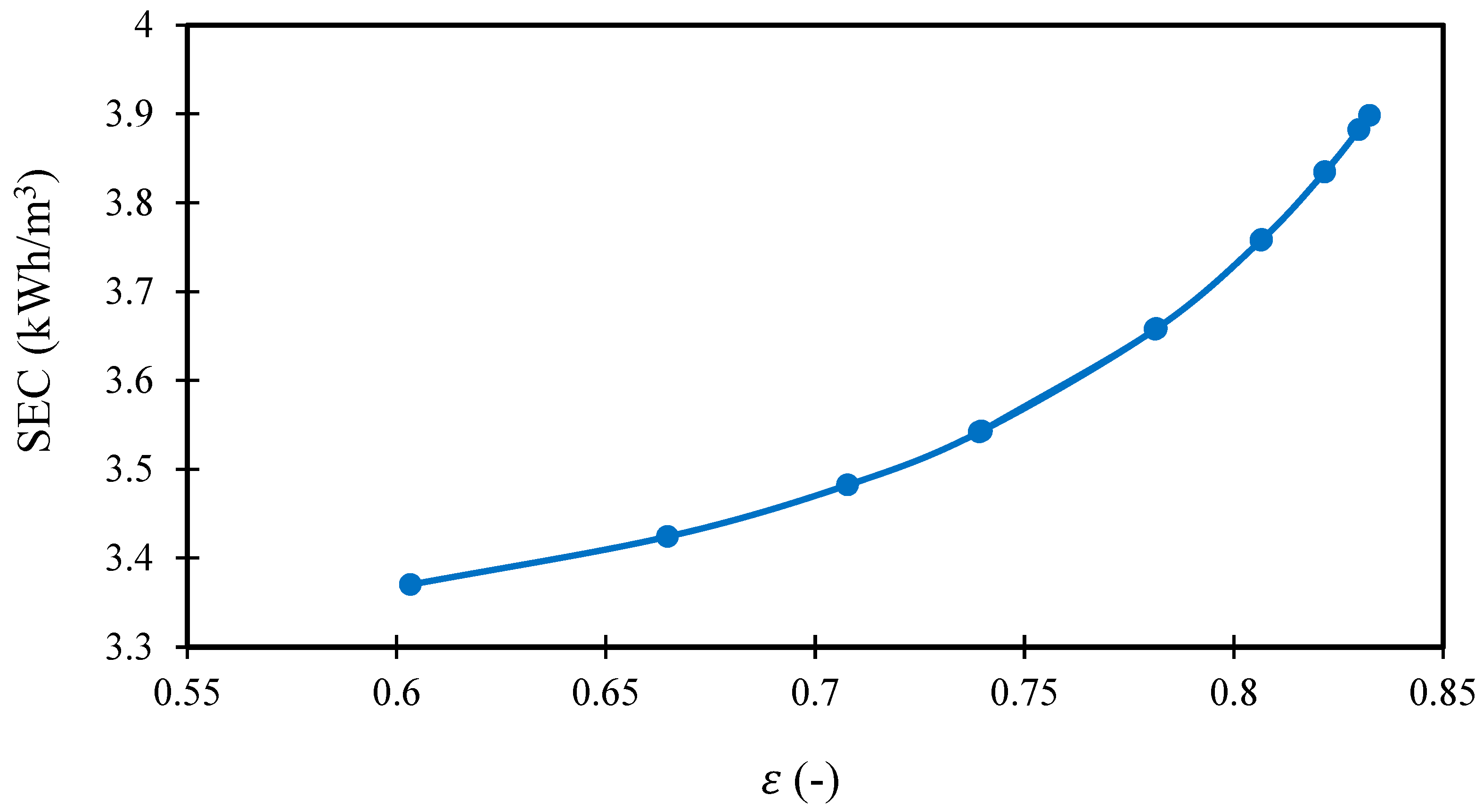
Figure 10 demonstrates an exponential relationship that links the specific energy consumption of the RO process, when using a UF−3 feed spacer, and the angle of the filaments, using the same set of operating conditions. Variations in the angle of the filaments introduce a change in the water flux (i.e., productivity) (
Figure 9), which can lead to a change in specific energy consumption (Equation (25) of
Table 1) at a fixed inlet feed pressure and feed flow rate. Clearly, it can be seen that a filament angle of 90° has a maximum specific energy consumption of about 3.9 kWh/m
3. More importantly, the lowest considered filament angle, 25°, can obtain the lowest specific energy consumption, of 3.37 kWh/m
3. Comparing to the original simulation results at a filament angle of 135°, using 25° would save 6.38% energy.
In summary, the above simulation results indicated that a filament angle of 90° introduced the lowest dimethylphenol rejection and water recovery levels (
Figure 8 and
Figure 9) and maximum specific energy consumption (
Figure 10), due to having the lowest values of mass transfer coefficient and axial velocity (at a greater influence of concentration polarization) (
Figure 6), in addition to having the lowest pressure drop (
Figure 5). This is in comparison to working with the lowest filament angle of 25°, which would lead to the opposite results (the highest axial velocity, highest water flux, highest mass transfer coefficient, highest dimethylphenol removal, and lowest specific energy consumption) and fit the goal of improving the performance indicators of a spiral wound module of the RO process, concerning the removal of dimethylphenol from wastewater. In this regard, researchers and engineers might consider varying the angle of the filaments of a UF−3 feed spacer, to strike a compromise between energy consumption, mass transfer efficiency, pressure drop, dimethylphenol rejection, water recovery, and specific energy consumption. This modification has the potential to result in more economical and energy-efficient operations in desalination facilities and other RO-related applications. However, it is important to consider potential trade-offs and practical limitations associated with decreasing the height of the feed spacer in RO systems. This is due to the possibility of reducing the effective membrane area available for filtration when using a shorter feed spacer. However, the current study focuses on the treatment of a low-concentration pollutant (dimethylphenol), with an insignificant tendency for considerable concentration polarization and fouling propensity. Therefore, the main objective was to achieve maximum dimethylphenol rejection, which is currently attained using the shortest feed spacer.
4.3. Effects of Porosity
Examining critical factors that affect the system’s overall efficiency is necessary for analysing the impact of porosity on the hydrodynamic features and performance metrics of a spiral wound module in the RO process. Referring to Equation (21) of
Table 1, the porosity is affected by the angle of the filaments, the height of the feed spacer, and the characteristic design parameters of mesh sizes and filament diameters. Furthermore, it should be noted that variable porosity can also be adjusted by modifying the spacers’ geometry, thickness, and placement. Examining several materials for the spacers that have diverse porosities by nature can also be advantageous. This can specifically be achieved by selecting materials with a variety of pore shapes, such as materials with regulated pore size distributions or porous polymers. More importantly, the current simulation characterises the variation in porosity due to changes in the angle of the filaments, when other influences are fixed.
Figure 11 shows that an increase in the filament angle up to 90° causes a continuous rise in porosity, and then it clearly decreases after 90°.
Figure 11 shows that the optimum value of the angle of filaments, of 90°, led to a maximum porosity of 0.83.
Firstly, it should be noted that this simulation has been carried out using similar inlet conditions as those described in the previous sections. Lower resistance and pressure drops are frequently caused by a higher porosity.
Figure 12 depicts the impact of porosity on the friction factor and pressure drop.
Figure 12 shows that porosity has a noteworthy impact on the pressure drop, similar to the impact of the angle of the flow diversion. An increase in porosity leads to a reduction in the pressure drop, which is associated with a reduction in concentration polarization impact. Statistically, an increase in porosity from 0.6 to 0.83 causes a reduction in the pressure drop of approximately 77%. A higher porosity enables a lower intensity of turbulence and less direct contact between the membrane surface and the feed solution, with a lower mass transfer coefficient. Therefore, it is fair to expect that an increase in porosity would cause a continuous decrease in axial velocity, corresponding to reductions in the friction factor and the pressure drop, due to the considerable influence of concentration polarization. Accordingly, these conditions would enable a higher solute flux, which introduces a lower solute rejection.
Figure 13 shows that an increase in porosity causes a reduction in axial velocity, which leads to a reduction in the mass transfer coefficient. Therefore, it is important to reduce the porosity, in order to enhance the mass transfer coefficient and dimethylphenol rejection. Accordingly,
Figure 14 depicts the negative influence of increasing the porosity on both dimethylphenol rejection and water recovery, as a result to reducing the axial velocity. Statistically, the porosity of 0.6 assumes the maximum dimethylphenol rejection of 99.5%, compared to the original dimethylphenol rejection of 98.81% at 0.763 porosity. Indeed, this is another proof of the necessity of conducting an adjustment of the original design of the UF−3 feed spacer, to hit the highest level of removal for dimethylphenol of 100% (especially with the aid given by optimising the operating conditions). In summary, it can be said that the optimal operation of the RO process, and specifically dimethylphenol rejection, is accomplished within the lowest porosity value.
Due to having lower rate of turbulence inside the feed channel due to increasing the porosity, a lower permeation of water (i.e., lower water recovery at fixed inlet feed flow rate) is introduced. Thus, a rise in specific energy consumption is expected, due to the increase in porosity, as illustrated in
Figure 15. Statistically, the increase in porosity from 0.6 to 0.83 results in an upsurge of around 16% in specific energy consumption.
5. Conclusions
The RO process has been widely used for the removal of many toxic compounds from wastewater. As an essential part of the spiral wound modules used in the RO process, the present study demonstrated the key role of the feed spacer, as it plays a substantial role in determining the pressure drop and crossflow velocity of the feed channel. The crossflow velocity, pressure drop, mass transfer coefficient, friction factor, water recovery, and solute rejection are typically linked to the design parameters of the feed spacer, including the height of the feed spacer, the angle of the filaments, and the porosity.
Using a simulation-based model, the current study attempted to analyse the hydrodynamics and design parameters of the spiral wound membrane module, containing a UF−3 feed spacer for the elimination of dimethylphenol from wastewater. Thus, a thorough investigation was carried out to discuss and analyse the performance indicators of a single RO process for the treatment of dimethylphenol solution under variable design parameters of the feed spacer (the feed channel height, the angle of the filaments, and the porosity).
Referring to the simulation results, it is obvious that the design parameters of the UF−3 feed spacer have a considerable influence on the process’ outcomes, due to their direct influence on the pressure, mass transfer coefficient, water flux, and solute flux.
To accomplish the highest dimethylphenol rejection, highest water recovery, and lowest specific energy consumption, the following recommendations for the design parameters of the UF-3 feed spacer should be taken into consideration:
It is beneficial to maintain the usage of the actual feed channel height, as it has the highest mass transfer coefficient, with elevated water flux and reduced solute flux through the membrane pores.
Compared to the original angle of the filaments, the lowest value is commensurate with attaining the optimal operation. This specifically introduces the highest water recovery, highest dimethylphenol rejection, and lowest specific energy consumption.
Compared to the original porosity, it is recommended to utilize the lowest porosity to maintain the efficient operation of the RO process, especially for wastewater treatment with very low pollutant concentrations. This enables the achievement the highest dimethylphenol rejection and water recovery levels, in addition to reducing specific energy consumption.
Statistically, the utilization of optimal design parameters for the UF−3 feed spacer, with a filament angle of 25° and a porosity of 0.6, respectively, is feasible for achieving the maximum removal of dimethylphenol from wastewater (greater than 99.5%) and the lowest specific energy consumption of 3.37 kWh/m3. Specifically, this critically introduces improvements of 0.7% for dimethylphenol rejection and 6.4% for specific energy consumption, compared to the original values. Beyond the obtained results of the current study, it is still necessary to investigate the simultaneous optimal values of feed spacer design parameters, which enable the introduction of a novel design of a feed spacer, specifically for the elimination of pollutants from wastewater with a feed concentration lower than 1000 ppm.


 ,
, 


