Experimental Study on Erosion and Sedimentation Patterns Downstream of a W-weir in a Sinusoidal Mild Bend


1
Department of Water Engineering, University of Tabriz, Tabriz 5166616471, Iran
2
Department of Civil, Architectural and Environmental Engineering University of Napoli Federico II, 80125 Napoli, Italy
*
Author to whom correspondence should be addressed.
Water 2017, 9(9), 638; https://doi.org/10.3390/w9090638
Submission received: 18 June 2017
/
Revised: 19 August 2017
/
Accepted: 23 August 2017
/
Published: 29 August 2017
Abstract
:Erosion in river bends causes loss of agricultural lands, adjacent facilities, and fish habitat. W-weir structures are recommended for controlling and reducing soil erosion as well as developing habitat for fish and other aquatic organisms. This paper presents the results of an experimental study carried out to investigate the effect of a W-weir structure on a sinusoidal channel with a sinuosity of 1.12 on the scour volume and type. The W-weir was applied in three heights (0.5, 1, and 1.5) with ratio (the height of weir to flow depth ratio) and different hydraulic conditions (inflow Froude numbers 0.107, 0.142, and 0.178) tested for each structure. Bed topography was measured at the end of each experiment, and from that the types of scouring, maximum scour depth and length, as well as maximum ripple height and length were computed. Furthermore, by decreasing the height of W-weir from = 1.5 to = 0.5, the scour volume decreased from 24 to 78 percent on average for different inflow Froude numbers. The angle of inner arms of W-weir was chosen as 50°, 64°, 86°, and 124°. Minimum scour volume occurred in the angle of inner arms of w-weir 64° for different heights of W-weir tested. Finally, two scour morphologies were observed. This study provides insights to guide and design W-weir structures for river restoration projects.
1. Introduction
Rivers are significant components of ecosystems which are necessary elements in the generation, formation, evolution, and development of civilizations. Different methods can be applied to protect the river from erosion. These methods can be direct or indirect. Direct and indirect procedures are utilized for controlling and reducing the erosion in riverine environments and preclude lateral migration. Examples of direct methods are establishing covers, retaining walls, vegetation, etc. Indirect methods are focused on the modification of the flow patterns, the reduction of flow velocity at banks, or the deviation of flow direction from the bank toward the river. Submerged vanes, spur dikes, bend-way weirs, and other in-stream structures might be utilized in this regard [1].
Water level rises and hydrostatic pressure increases in river bends. If the flow has a non-uniform velocity, the pressure gradient is insufficient for the faster-moving particles and more than sufficient for the slower ones. The water level decreases at the inner bank of a bend in the river, which creates a rotational flow. A secondary flow is therefore formed, with the faster fluid moving to the outside of the bend and the slower fluid to the inside of the bend [2]. Natural meandering rivers are quite unstable due to bank erosion downstream of concave banks. Deeper flows are prevalent in bend and higher velocities along the outer concave banks. The flow depth at crossings is relatively shallow compared to that at river bend. Meandering rivers migrate gradually, and hence sinuosity tends to increase. If the river banks are rigid, erosion is just limited to the bed, while in the case of erodible banks, the outer bank erodes and eventually collapses. This flow pattern affects the outer and inner banks of alluvial river bend morphology.
Erosion and sedimentation at the river bend are complex phenomena. Erosion causes disturbance of private and public lands, damages aquatic and riparian ecosystems, and degrades water quality. Structures like W-weir are usually used to minimize the effects of rotational flow in river bend and to restore and optimize river banks and beds [3]. The structures reduce near-bank shear stress and stream power while increasing center flume shear stress and stream power to retain both flood-flow and sediment transport capacity. To maintain or restore a river’s habitat diversity, different structural approaches have been proposed [4,5,6]. Weirs can be used in rivers to diversify habitat and provide grade control. They can even assist in maintaining a stable dimension pattern and profile [4].
The cross-vane, W-weir, and J-hook vane are structures that can be implemented to maintain or enhance river stability and function and to accomplish multiple objectives. These structures have been successfully applied in natural channel design for river restoration, bank stabilization, grade control, irrigation diversions, fish habitat enhancement, bridge protection, and recreational boating [1,5,6,7,8,9,10]. Most of the structures implemented involve the “hardening” of the banks. Changes in near-bank stress and stream power associated with unstable channels can accelerate bank erosion. Any structures that can reduce near-bank stress will reduce bank erosion by several orders of magnitude [1]. Nonetheless, few studies have specifically focused on grade control structures. The design details of eco-friendly grade control structures including W-weirs were presented by Rosgen [1].
Several experimental studies using weir-type structures have been carried out to enhance hydraulic and aeration performance [11,12,13,14,15]. Bhuiyan et al. [16,17] studied the flow turbulence characteristics and scour development downstream of W-weir and vanes at the river bend under clear water and live-bed conditions. They did experiments in a sinuous channel with a width of 1.6 meters, sinuosity of 1.38, and a longitudinal slope of 0.00133. The angle of vanes connected to the bank and angle of W-weir arms were 30° to the bank downstream. Results of the study indicated that two scour holes were created after the W-weir was installed. The W-weir did not affect the sediment transport along the meandering channel and also upstream of channel bed. Scurlock et al. [18] focused on maximum velocity effects from vane-dike installations in a channel bend. They developed some equations for representing maximum changes in flow velocities at the outer bank, inner-bank, and centerline locations within a channel bend. From the installation of the vane-dike, they presented some equations to predict the maximum velocities in the presence of the vane-dike at the channel bends. Scurlock et al. [19] conducted an experimental study on scouring downstream of A, U, and W-weirs, including several experiments to estimate the maximum scour depth downstream of three different types of grade-control structures. They presented an equation for each of the weirs that estimates the maximum scour depth. Equations were also compared with equations obtained from former studies. Pagliara et al. [20] examined W-weir in a straight rectangular flume under clear water conditions in order to analyze erosion downstream of the weirs. Their results indicated that the water level difference between downstream and upstream, the particle Froude number, the height of the structure, and the depth of flow downstream are the primary parameters for estimating maximum scour depth, maximum scour length, maximum ridge depth, and length, and the location of maximum scour. Guan et al. [21] conducted a series of experiments to investigate flow turbulence in a scour hole downstream of a submerged weir. They found that a recirculation zone and flow reattachment region developed along the flume centerline in a longitudinal direction. Turbulence structures at the upstream end of the recirculation zone governed the dimensions of the scour hole. Bahrami Yarahmadi and Shafai Bejestan [22] studied the effects of variations in the space between triangular vanes on scour-deposition patterns under different hydraulic conditions in a 90-degree mild bend. They observed that the single vane decreased the depth-averaged velocity near the outer bank both upstream (up to 44%) and downstream of the vane. By installing a single vane at the outer bank, the flow was deflected from the outer bank toward the middle of the flume. Pagliara and Kurdistani [23] studied scour phenomena downstream of wooden stream restoration structures. They found that using log-frame deflectors instead of log deflectors resulted in a better riverbank protection. Pagliara et al. [24] investigated scour phenomenon downstream of block ramps. They showed that the decrease of the curvature radius caused a three- dimensional (3D) equilibrium scour morphology. Kurdistani and Pagliara [25] studied the scour phenomena and bed morphologies downstream of cross-vane structures installed in a curved channel. Based on dimensional analysis, empirical equations were developed to predict the maximum scour depth for different combinations of hydraulic conditions, channel bend, structure orientation with respect to the flow direction, and structure geometry. The densimetric Froude number, the drop height, the tailwater, the height of the structure, and the channel curvature were the main parameters affecting the scour size and morphology. Their results indicated that structure orientation had no significant effect on scour depth and length or on ridge height and length. These experimental studies are listed in Table 1.
Structures are often selected and installed without an understanding of sediment transport and violate the dimension, pattern, and profile of the stable river [1]. This is important to precisely know how the scour morphology around these types of structures changes for different hydraulic conditions and to support designers in selecting the best structure configuration to stabilize the river bed [23]. Only a few types of research have been carried out using W-weir in the sinuous channel to identify the effect of the angle of inner arms on scouring. The aim of this study is to experimentally analyze the scour geometry downstream of W-weirs in a sinuous channel and the effect of the structure height and the angle of inner arms of the W-weir in scouring formation.
2. Materials and Methods
2.1. Experimental Setup
The experiments were conducted in the hydraulic laboratory of the University of Tabriz in a horizontal rectangular flume with a sinuosity of 1.12, 0.35 m wide, 0.5 m high, and 6.7 m long. The sediment used in the experiments was sand, with a mean diameter of 1.2 mm. In all experiments, the sediment size distribution was uniform, with a geometric standard deviation of = 1.21. The flow discharge was measured by an ultrasonic flow meter with an accuracy of ±0.1 L/s. An ultrasonic Data Logic US30 distance measuring sensor with the accuracy of ±0.1 mm was used for recording the water level. Bed topography was measured by a laser distance meter with an accuracy of ±0.1 mm. The W-weir was installed in the flume (W is looking in the downstream direction). The height of the crest of W-weir varied across the section (Figure 1d). Based on Rosgen [1], the angle between the outer arms of the crest and the bank were symmetrical in plan and angled upstream at 25° (Figure 1c).
All tests were carried out in clear water conditions. The equilibrium phase was attained when the scour dimensions no longer changed significantly. Because the main goal of this study was to compare bed scour pattern for the different inner arm angles and structure heights in different hydraulic conditions, a 3-h time interval was adequate [28]. The flow discharge, , was 7.5, 10, and 12.5 L/s with a flow depth, h, at the upstream straight reach of the bend of 0.16 m. Thus, the inflow Froude numbers were 0.107, 0.142, and 0.178, respectively. In the experiments, suggested standards by the previously published literature (e.g., Rosgen [1] and Bhuiyan et al. [17]) were followed in selecting the W-weir sizes. Figure 1c,d illustrates the W-weir characteristics and sizes. In Figure 1, the terms , , and represent the height of outer arms from sediment bed, the height of the inner arm from sediment bed, the angle between inner arms, and width of the sinuous flume, respectively.
To investigate the effect of the structure height and the effect of the different inner arm angles, two series of experiments were conducted. The first series included tests with three different heights of W-weir (0.24 m, 0.16 m, and 0.08 m), and the second series contained tests with different values of (124°, 86°, 64°, and 50°). All experiments were conducted in different hydraulic conditions ( 0.107, 0.142, and 0.178). All experimental ranges are shown in Table 2.
2.2. Dimensional Analysis
W-weir scour depth (), length (), and volume of the scour hole () can be described by the following set of variables: the structure height (), the angle between the outer arms and the river bank structure (), the angle of inner arms (), the gravitational acceleration (), the water density (), the fluid dynamic viscosity (), the flow average velocity (), the flow average depth (), the bed material density (), and the mean particle diameter (). According to introduced variables:
According to the Buckingham π theory, the following dimensionless parameters are achieved:
Reynolds number is achieved by a combination of () and (); the approaching flow Reynolds number was measured upstream of the structure and varied 11.2 × 10³, 14.74 × 10³, and 18.47 × 10³, indicating a turbulent flow condition for all tests. Based on Rosgen [1], the optimized angle was between 20° to 30° where lateral arms were linked to the bank, which is the constant value in this study and is equivalent to 25°, and Equation (2) can be transformed as follows:
In open channel flows, the turbulent boundary layer may be partially- or fully-developed. In steady flows, the boundary shear stress, , and the shear velocity, , may be estimated by several methods. Most are based upon a comparison between velocity distribution data on the channel centerline and theoretical profiles [29]. For open channel flows, the boundary shear stress and the shear velocity may be estimated from the mean flow velocity, , and the Darcy–Weisbach friction factor f:
where f is the Darcy friction factor and is defined by the Colebrook–White equation [30]:
Accordingly, the Rouse number on a bed is calculated by the following equation:
where is sediment fall velocity and k = 0.4 (Von Karman’s constant).
3. Results and Discussion
3.1. Scour Typologies
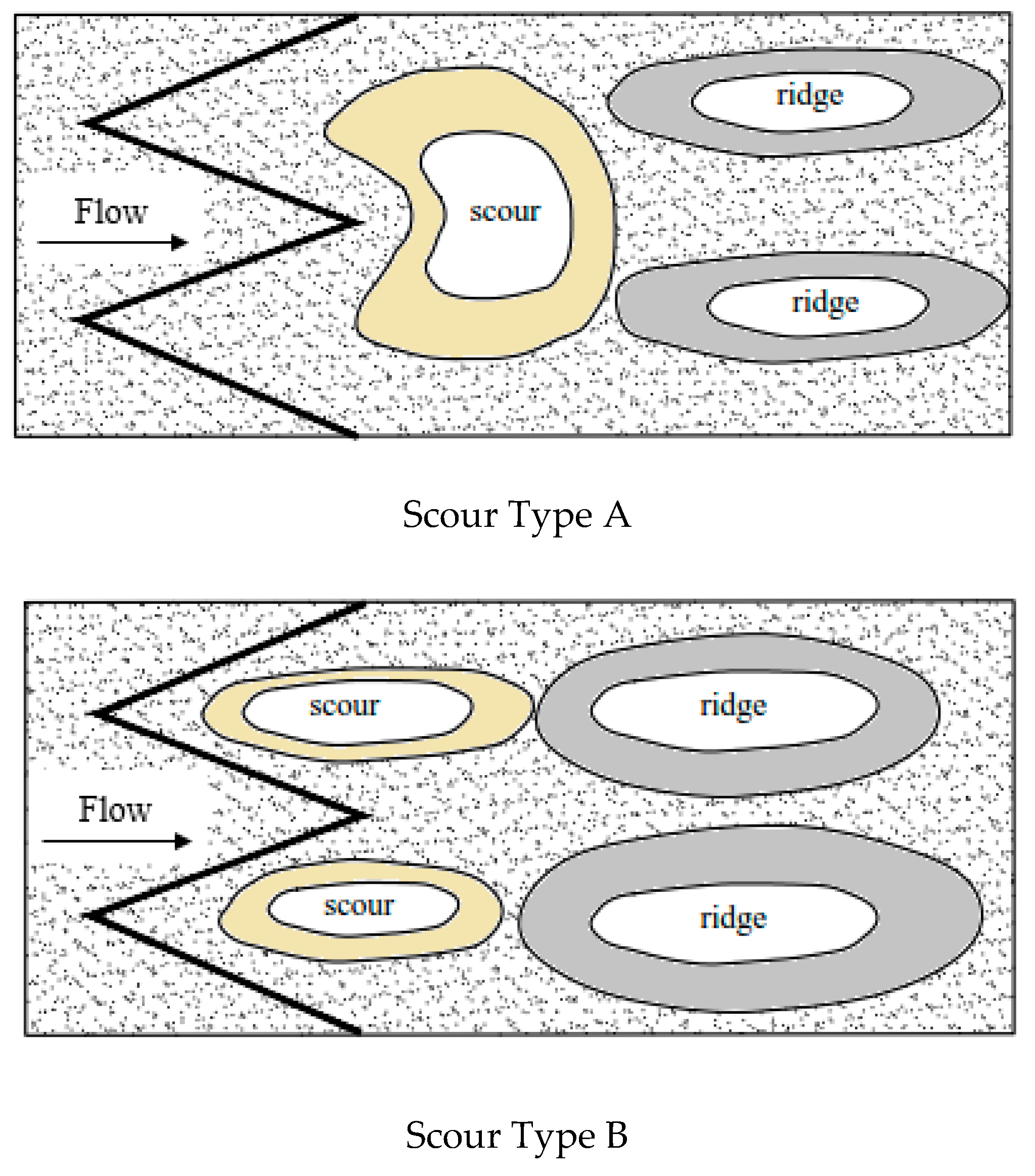
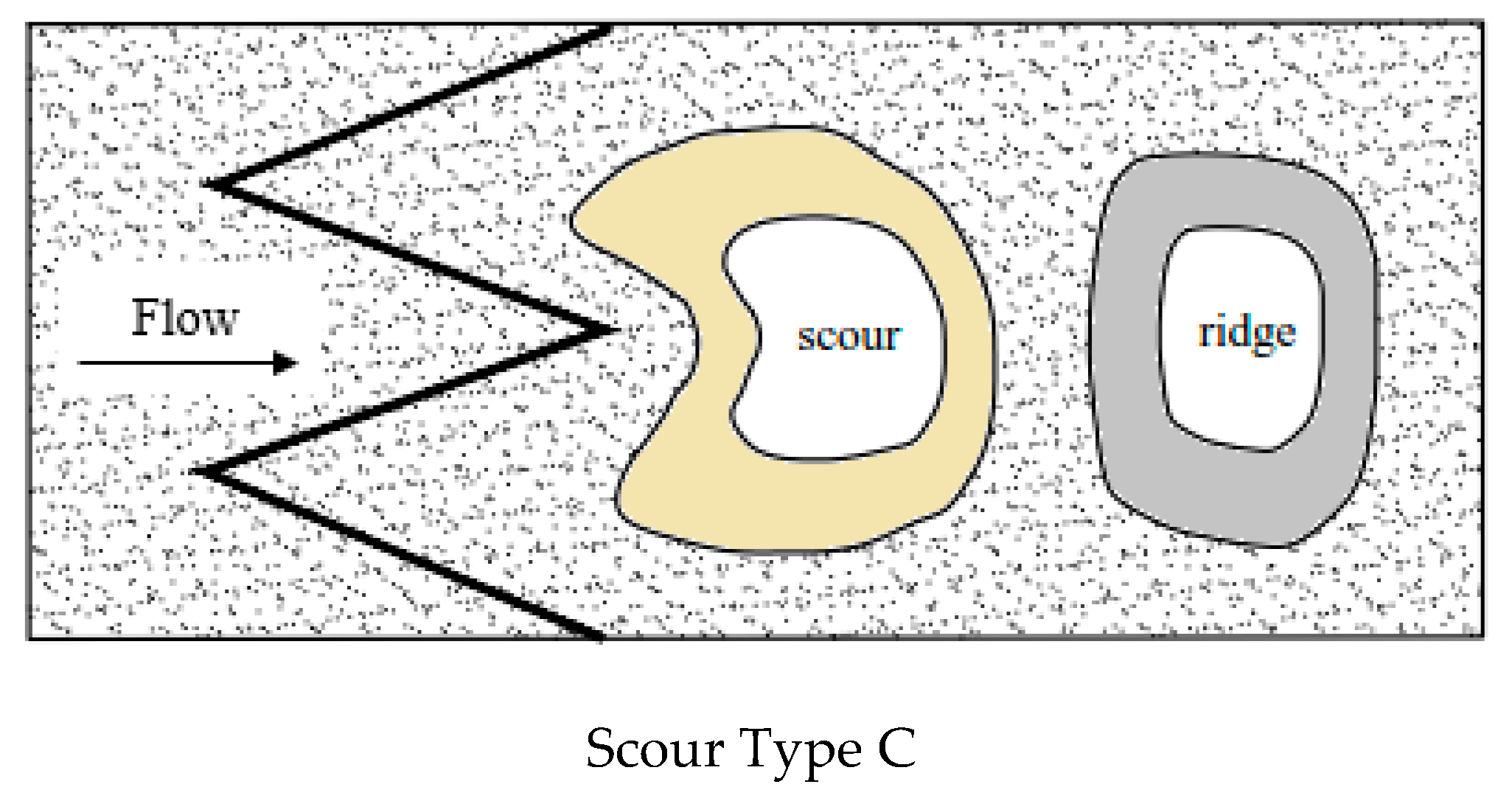
Bhuiyan et al. [16] and Scurlock et al. [19] presented a unique scour morphology containing two separate scour holes downstream of W-weir structures. According to Pagliara et al. [20], the height of the structure hst (defined as the average height of the top of the stones over the channel bed); the difference between the water surfaces upstream and downstream of the structure Δh; and the densimetric Froude numbers Fd were used to classify rock W-weir experimental data. They showed that three types of scour morphologies could happen downstream of grade-control structures. Type A morphology is characterized by one scour hole, and two ridges; type B morphology is characterized by two scour holes, and two ridges; and type C has one scour hole only and one ridge. These three types are presented in Figure 2. During the present experiments with the W-weir, two morphologies were observed—namely, types B and C. Based on this definition, all experimental results are reported in Table 2.
Results of experimental study indicated that the characteristics of the scour downstream of the structure differ by the variation of the angle of inner arms, the height of the structure, and the flow discharges.
Comparison of the scour type and experimental data show that scour type varies with the weir parameters. Scour type of morphologies and the angle of inner arms of W-weir are presented in Table 2. With the change in the angle of inner arms from 50° to 64°, 64° to 86°, and 86° to 124°, the center of the weir (Figure 1c) displaced upstream and the length of the crest decreased. With the increase in inner angle, flow deviated toward the flume centerline. Results showed that for all values and Fr, in and the scour type B occurred.
It was clearly visible that the scour hole was mostly located in the center of the flume with respect to the installation of weir with . In other words, with , scour type C occurred for all values of and Fr. The present experiments also showed that if , scour type B occurred for values of = 0.5 with all values of Fr, while for values of = 1.5 scour type C was formed. However, Pagliara et al. [20] reported three types of scour morphologies. This discrepancy can be attributed to the test setup, since in this research the experiments were carried out in a flume with a sinuosity of 1.12, while Pagliara et al. [20] conducted the experiments with rock W-weir structures in a straight flume.
3.2. The Effect of the Angle of the Inner Arms of the W-Weir on Sediment Transport
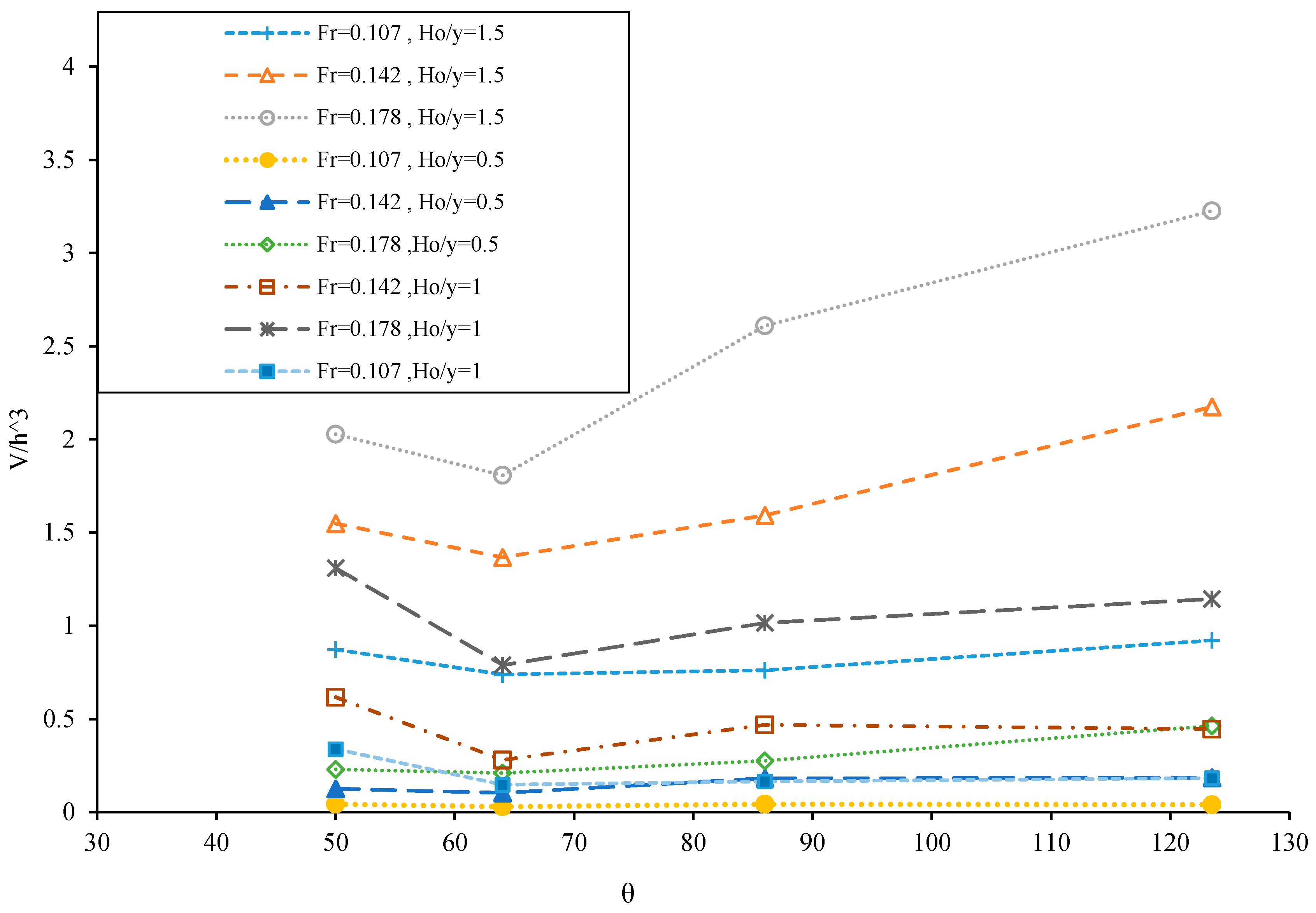
In this study the flume sidewalls were made of plexiglass. In reality, scour in a bend might be reduced or at least the outer-bank profile would be changed due to the contribution of bank erosion products. This shows the effect of the angle of inner arms () on the size of scour. The weir height was kept constant as 0.24 m, 0.16 m, and 0.08 m, so for each weir height, the various angles of the inner arms were tested. The angle of inner arms was chosen according to Table 3. All experimental data were plotted in a graph versus , as shown in Figure 3. The size of scour increased with increasing angle of inner arms (), the size of scour hole was minimum when the inner angle of arms was 64°. By increasing the inflow Froude number, the maximum scour depth increased. Changes of scour downstream were not significant for Run 1 to Run 4. This is close to the higher range of values observed in triangular vanes by Bahrami Yarahmadi and Shafai Bejestan [22].
Visual observations (color injection) indicated that with increasing with inner angle of W-weir, the whole near-outer bank flow deviated toward the flume centerline. This created scour hole and ridge. A change in flow pattern was observed when the angle of the W-weir was increased. By increasing the inflow Froude number, the maximum scour depth increased.
3.3. Effect of the Height of W-Weir on the Scour Volume
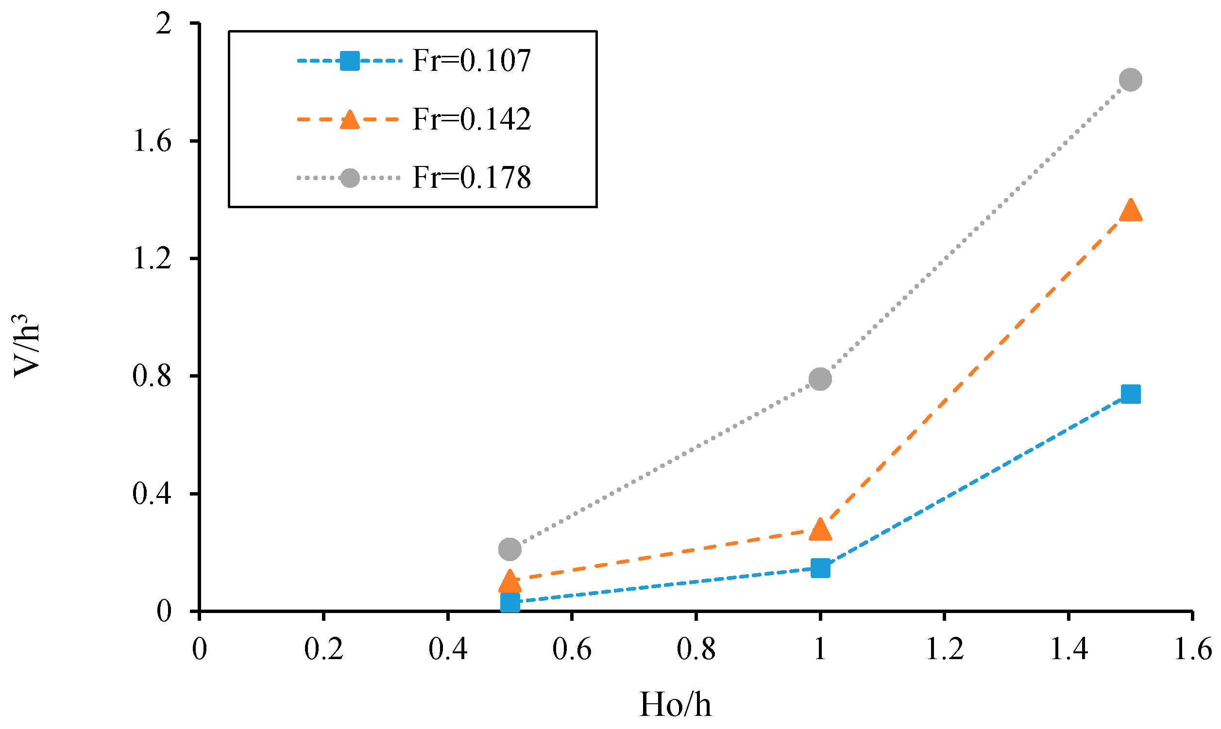
For each angle between the inner arms of W-weir (124°, 86°, 64°, and 50°), three heights of the weir in different inflow Froude numbers were tested. The results showed that the smallest scour hole was created for the angle of inner arms of W-weir 64° (Figure 3). The volume scour of W-weir at different heights of weir for the test with = 64° is plotted in Figure 4.
The results showed that the W-weir changed the pattern of sediment transport downstream of the bend. Observations showed that by decreasing the height of W-weir, the size of scour decreased. The scour volume in the presence of W-weir at the lowest height caused the minimum scour depth with = 64°. The approach flow was accelerated at the crest of the weir. The upstream-oriented sloping crests, and the non-uniform approach flow both contribute to the generation of vortices downstream of the structure. Downstream of the weir, a large recirculation zone developed and vortices could be clearly observed. This causes turbulence with flow interactions in all directions where deep and partially separated scour holes are formed [3].
Like other grade control structures the W-weir caused mixing of the flow. It appears that the scour hole is almost completely located toward the center of the flume and the ridge also develops toward the center of the flume. According to Bhuiyan et al. [16], over the inclined section of the two upstream oriented arms of the W-weir, the flow was directed towards the centerline of the flume. Flow over the inclined sections of the downstream-oriented crest of the weir in the flume forced the flow towards the center of the flume. The scour depth downstream of the weir decreased as the inflow Froude number decreased from 0.178 to 0.107. The percent reduction of the volume scour at Run 10 and Run 6 was calculated to be 59% and 78%, respectively. As illustrated in Figure 4, the minimum scour volume occurred at low structure height and low Fr. When the discharge is increased, the turbulence generation is increased due to shearing and interaction of the flow. The results were consistent with the results of previous studies [16,17,20].
3.4. Scour Morphologies and Maximum Scour Depth
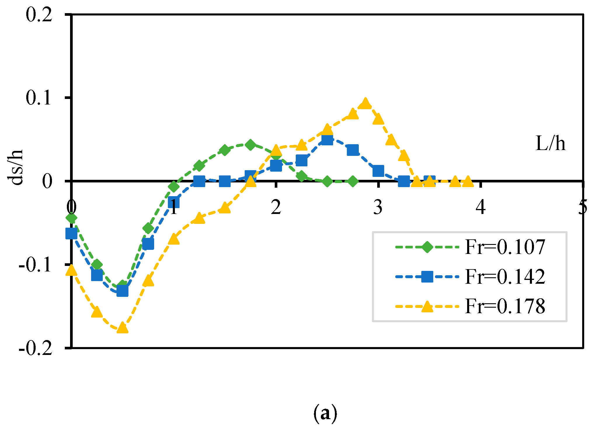
Weir construction creates obstruction to flow and dissipates energy, changing local flow conditions and in turn affecting solute transport locally and potentially downstream. The present experiments also showed that the minimum scour hole was created for the angle between the inner arms of W-weir 64°. Results of the study indicated that two scour holes were created downstream when a W-weir was installed with = 64°. The location of longitudinal profiles was measured in y/W = 0.25 (left side) and y/W = 0.75 (right side), where y is the coordinate in the y direction and W is the channel width. Figure 5, Figure 6 and Figure 7 compare longitudinal profile in y/W = 0.25 (left side) and y/W = 0.75 (right side) downstream of weir for three inflow Froude numbers for = 64°. Finally, the maximum scour depth was measured from initial bed level near the structure. As the weir was located in the flume, maximum transport occurred over the left-hand side. This is close to the observation of Bhuiyan et al. [16], with the weir at bankfull flow in the sinuous channel [16]. The maximum scour depth corresponds to longitudinal profiles at the y/W = 0.25, left-hand side of the flume, where the high-velocity core was associated with the lowest on the weir. The shallower scour depth corresponds to the scour hole on the right-hand side, where mean velocities were significantly lower.
As shown in Figure 5, with decreasing inflow Froude number from 0.178 to 0.142, in Run 34 to Run 22 the maximum scour depth in left and right sides decreased 29.1% and 12.2%, respectively; and with decreasing inflow Froude number from 0.178 to 0.107, the maximum scour depth in left and right sides decreased 108% and 72.3% percent, respectively. By increasing the inflow Froude number, the maximum scour depth increased.
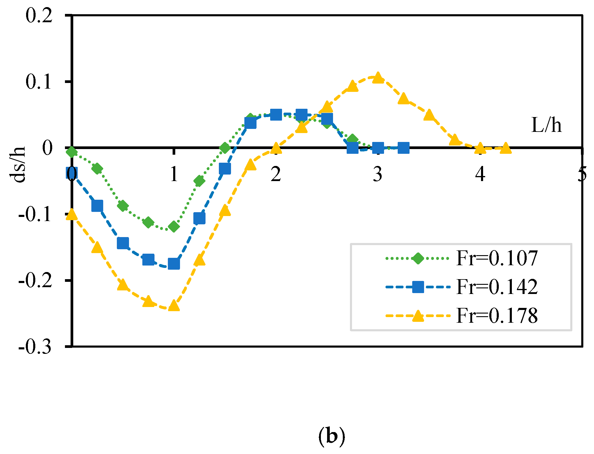
Figure 6 compares longitudinal profile, in y/W = 0.25 (left side) and y/W = 0.75 (right side) downstream of weir for Run 6, Run 18, and Run 30. With decreasing inflow Froude number from 0.178 to 0.142, in Run 30 to Run 18 the maximum scour depth in the left and the right sides decreased 138.8% and 62.1%, respectively; and with decreasing inflow Froude number from 0.178 to 0.107, the maximum scour depth in left and right sides decreased 108% and 72.3% percent, respectively. The longitudinal profile of the bed in y/W = 0.25 (left side) and y/W = 0.75 (right side) for the three Run 2, Run 14, and Run 26 were presented in Figure 7. Generally, through comparison of topography it is specified that the intensity of erosion downstream for the angle of 64° and Ho/h = 0.5 was less than in other cases. The water level rose and hydrostatic pressure increased on the left side (toward the outer bend) of the flume due to the centrifugal force. On the other hand, the water level fell in an inner bend that caused secondary flow where scour holes were formed in the outer bend. This procedure was observed in the presence of the W-weir as well, and W-weir installation reduced the effect of this force. This is close to the observed maximum scour with the grade control (cross vane) in a laboratory study by Kurdistani and Pagliara [23].
4. Conclusions
Weirs are constructed to control flow and to modify flow characteristics for river restoration. A clear understanding of their effects on the flow by different layouts of the structure is necessary to guide their design to attain the desired results. In this experimental study, the effect of variations in the height of W-weir () and the angle between the inner arms of W-weir () on scour-deposition patterns are presented. Based on the test observations and data analysis, the following main conclusions are drawn:
- By installing a W-weir, flow over the inclined sections of the downstream-oriented crest of the weir in the flume forced the flow towards the center of the flume. A W-weir can be installed in a river bend for bank protection.
- By installing a W-weir, local scour increased and the bed upstream did not change appreciably. No significant deposition of sediment occurred upstream of the structure. Downstream of the weir, two types of scour morphologies (type B and type C) were formed. The weir with scour type C can be designed in the river with the case of an erodible bank, because one scour formed in the middle of the channel and the whole near-outer bank flow deviated toward the flume centerline.
- The size of scour increased with increasing angle between the two inner arms (), the size of scour hole was minimum when the inner angle of arms was 64°. By increasing the inflow Froude number, the maximum scour depth increased.
- The size of scour hole in three heights of the weir ( 0.5, 1, 1.5) in different inflow Froude numbers was tested. The minimum scour depth occurred at 0.5 for the tests with all angles between inner arms. By increasing the inflow Froude number, the maximum scour depth increased.
The W-weir is a gently sloping structure that can be constructed with natural materials like boulders, logs, rock, etc. The choice should be made on environmental and economic grounds, as well as engineering needs. This weir could be installed to maintain the upstream water level and to control erosion/deposition in the river.
Acknowledgments
The authors would like to thank the vice-chancellor for research of University of Tabriz (IRAN) for providing financial support. The first author acknowledges that the time spent at the University of Napoli Federico II was partially supported by the Ministry of Science, Research, and Technology of IRAN.
Author Contributions
Milad Abdollahpour, Ali Hosseinzadeh Dalir and Davod Farsadizadeh designed and supervised the experiments. Milad Abdollahpour and Carlo Gualtieri conducted the analysis on the experimental data. Ali Hosseinzadeh Dalir and Davod Farsadizadeh edited the manuscript. Milad Abdollahpour and Carlo Gualtieri wrote the paper. All authors read and approved the final manuscript.
Conflicts of Interest
The authors declare no conflict of interest.
References
- Rosgen, D.L. The cross-vane, W-weir and J-hook vane structure: Their description and application for stream stabilization and river restoration. In Proceedings of the Wetlands Engineering and River Restoration Conference, Reno, VA, USA, 27–31 August 2001; ASCE: Reston, VA, USA; pp. 1–22. [Google Scholar]
- Blanckaert, K.; de Vriend, H.J. Secondary flow in sharp open-channel bends. J. Fluid Mech. 2004, 498, 353–380. [Google Scholar] [CrossRef]
- Bhuiyan, F.; Hey, R.D. Computation of three-dimensional flow field created by weir-type structure. Eng. Appl. Comput. Fluid Mech. 2007, 1, 350–360. [Google Scholar]
- Rosgen, D.L. Natural Channel and River Restoration Short Course Notes; Wildland Hydrology: Pagosa Springs, CO, USA, 1996. [Google Scholar]
- Hey, R.D. River Mechanics and Habitat Creation, Fisheries in the Year 2000; O’Gardy, K.T., Butterworth, A.J.B., Spillett, R.P., Domaniewski, J.C.J., Eds.; Institute of Fisheries Management: Nottingham, UK, 1992; pp. 271–285. [Google Scholar]
- Hey, R.D. Restoration of gravel bed rivers: Principles and Practice. In ‘Natural’ Channel Design: Perspective and Practice; Shrubsole, D., Ed.; Canadian Water Resources Association: Cambridge, ON, Canada, 1994; pp. 157–173. [Google Scholar]
- Hey, R.D. Environmentally Sensitive River Engineering. River Restoration; Petts, G., Calow, P., Eds.; Blackwell Science: Oxford, UK, 1996; pp. 80–105. [Google Scholar]
- Shields, F.D.; Knight, S.S.; Cooper, C.M. Incised stream physical habitat restoration with stone weir. Regul. Rivers Res. Manag. 1995, 10, 181–198. [Google Scholar] [CrossRef]
- Shields, F.D.; Morin, N.; Cooper, C.M. Large woody debris structure for sand-bed channels. J. Hydraul. Eng. 2004, 133, 208–217. [Google Scholar] [CrossRef]
- Garda, C.; Castleden, H.; Conrad, C. Monitoring, Restoration, and Source Water Protection: Canadian Community-Based Environmental Organizations’ Efforts towards Improving Aquatic Ecosystem Health. Water 2017, 9, 212. [Google Scholar] [CrossRef]
- Cassidy, J.J.; Gardner, C.A.; Peacock, R.T. Boarman labyrinth-crest spillway. J. Hydraul. Eng. 1985, 111, 398–416. [Google Scholar] [CrossRef]
- Watson, C.C.; Walters, R.W.; Hogan, S.A. Aeration performance of low drop weirs. J. Hydraul. Eng. 1998, 124, 65–71. [Google Scholar] [CrossRef]
- Wormleaton, P.R.; Soufiani, E. Aeration performance of triangular planform labyrinth weirs. J. Hydraul. Eng. 1998, 124, 709–719. [Google Scholar] [CrossRef]
- Kim, J.; Walters, R.W. Oxygen transfer at low drops weirs. J. Hydraul. Eng. 2001, 127, 604–610. [Google Scholar] [CrossRef]
- Kim, H.S.; Kimura, I.; Shimizu, Y. Experimental Investigations of Scour Pools around Porous Obstructions. Water 2016, 8, 498. [Google Scholar] [CrossRef]
- Bhuiyan, F.; Hey, R.D.; Wormleaton, P.R. River restoration using W-weir. J. Hydraul. Eng. 2007, 133, 596–609. [Google Scholar] [CrossRef]
- Bhuiyan, F.; Hey, R.D.; Wormleaton, P.R. Effect of Vanes and weirs on sediment meandering channels. J. Hydraul. Eng. 2009, 135, 339–349. [Google Scholar] [CrossRef]
- Scurlock, S.M.; Cox, A.L.; Thornton, C.I.; Baird, D.C. Maximum velocity effects from vane-dike installations in channel bends. In Proceedings of the World Environmental and Water Resources Congress, Albuquerque, NM, USA, 20–24 May 2012; ASCE: Reston, VA, USA, 2012; pp. 2614–2626. [Google Scholar]
- Scurlock, S.M.; Thornton, C.I.; Abt, S.R. Equilibrium scour downstream of three-dimensional grade-control structure. J. Hydraul. Eng. 2012, 138, 167–176. [Google Scholar] [CrossRef]
- Pagliara, S.; Kurdistani, S.M.; Cammarata, L. Scour of clear water Rock W-weirs in Straight Rivers. J. Hydraul. Eng. 2014. [Google Scholar] [CrossRef]
- Guan, D.; Melville, B.; Friedrich, H. Flow patterns and turbulence structures in a scour hole downstream of a submerged weir. J. Hydraul. Eng. 2014, 140, 68–76. [Google Scholar] [CrossRef]
- Yarahmadi, M.B.; Bajestan, M.S. Sediment management and flow patterns at river bend due to triangular vanes attached to the bank. J. Hydro-Environ. Res. 2016, 10, 64–75. [Google Scholar] [CrossRef]
- Pagliara, S.; Kurdistani, S.M. Flume experiments on scour downstream of wood stream restoration structures. Geomorphology 2017, 279, 141–149. [Google Scholar] [CrossRef]
- Pagliara, S.; Radecki-Pawlik, A.; Palermo, M.; Plesinski, K. Block ramps in curved rivers: Morphology analysis and prototype data supported design criteria for mild bed slopes. River Res. Appl. 2017, 33, 427–437. [Google Scholar] [CrossRef]
- Kurdistani, S.M.; Pagliara, S. Experimental Study on Cross-Vane Scour Morphology in Curved Horizontal Channels. J. Irrig. Drain. Eng. 2017. [Google Scholar] [CrossRef]
- Pagliara, S.; Kurdistani, S.M. Scour downstream of cross-vane structures. J. Hydro-Environ. Res. 2013, 7, 236–242. [Google Scholar] [CrossRef]
- Pagliara, S.; Kurdistani, S.M. Scour characteristics downstream of grade-control structures. In River FLow 2014; Taylor & Francis Group: London, UK, 2014. [Google Scholar]
- Johnson, P.A.; Hey, R.D.; Tessier, M.; Rosgen, D.L. Use of vanes for control of scour at vertical wall abutments. J. Hydraul. Eng. 2001, 127, 772–778. [Google Scholar] [CrossRef]
- Koch, C.; Chanson, H. An Experimental Study of Tidal Bores and Positive Surges: Hydrodynamics and Turbulence of the Bore Front; Report No. CH56/05; Department of Civil Engineering, The University of Queensland: Brisbane, Australia, 2005; p. 170. ISBN 1864998245. [Google Scholar]
- Colebrook, C.F. Turbulent flow in pipes with a particular reference to the transition region between smooth and rough pipe laws. J. Inst. Civ. Eng. 1939, 11, 133–156. [Google Scholar] [CrossRef]
- Bombardelli, F.A.; Moreno, P. Exchanges at the bed sediments-water column interface. In Fluid Mechanics of Environmental Interfaces, 2nd ed.; Gualtieri, C., Mihailović, D.T., Eds.; CRC Press/Balkema: Leiden, The Netherlands; pp. 221–253. ISBN 978-0-415-62156-4.
Figure 1.
(a) Plan view of the flume; (b) Photograph of the W-weir in the flume; (c) Sketch of the W-weir parameter; (d) Cross-sectional view of W-weir.
Figure 1.
(a) Plan view of the flume; (b) Photograph of the W-weir in the flume; (c) Sketch of the W-weir parameter; (d) Cross-sectional view of W-weir.
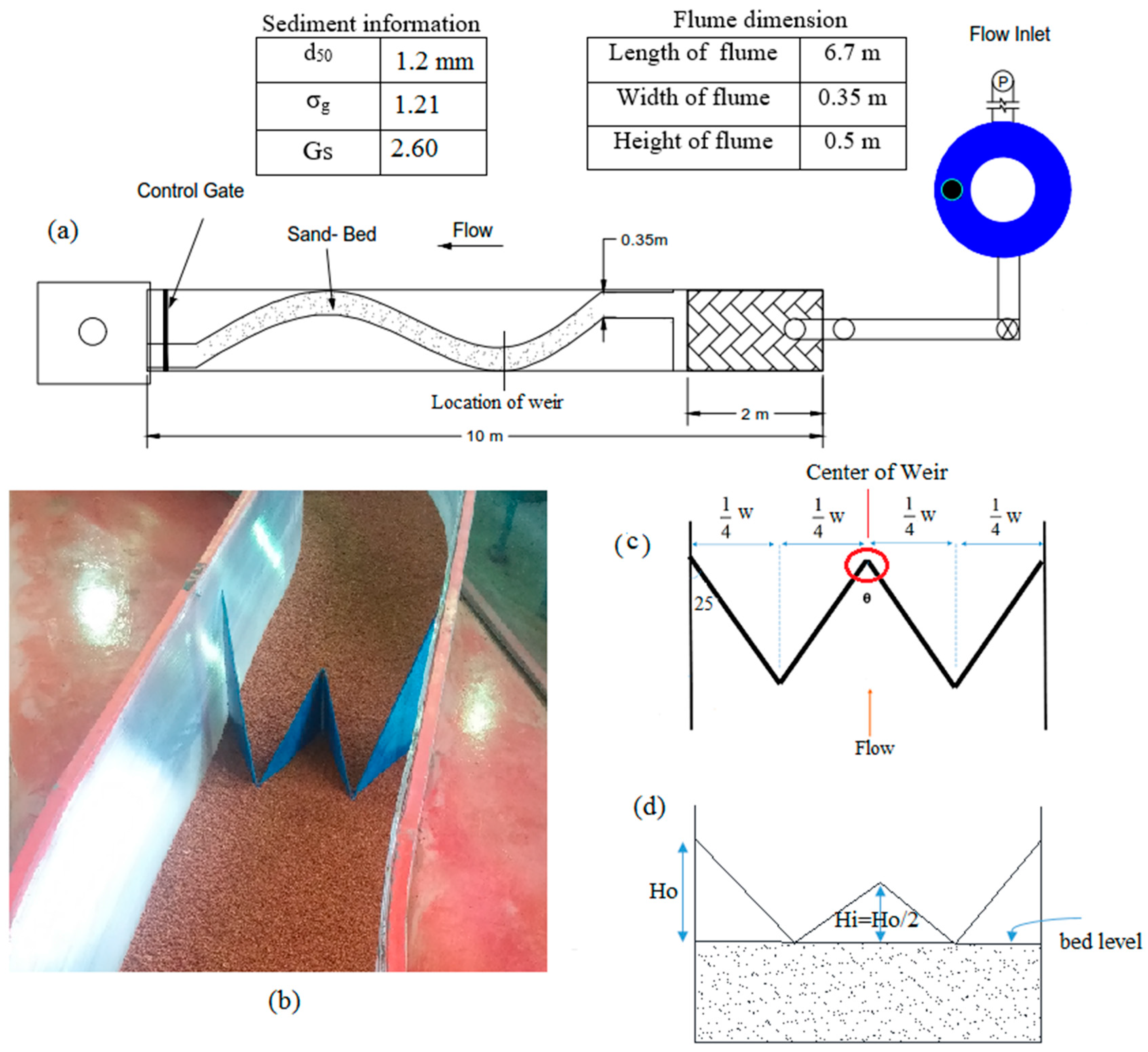
Figure 2.
Different types of scour process downstream of W-weirs.


Figure 3.
The effect of inner angle of W-weir on the size of scour.

Figure 4.
Comparison of the height of W-weir for = 64°.

Figure 5.
Comparison of the longitudinal profile of the bed for Run 10, Run 22, and Run 34: (a) y/W = 0.25 (left side); (b) y/W = 0.75 (right side).
Figure 5.
Comparison of the longitudinal profile of the bed for Run 10, Run 22, and Run 34: (a) y/W = 0.25 (left side); (b) y/W = 0.75 (right side).
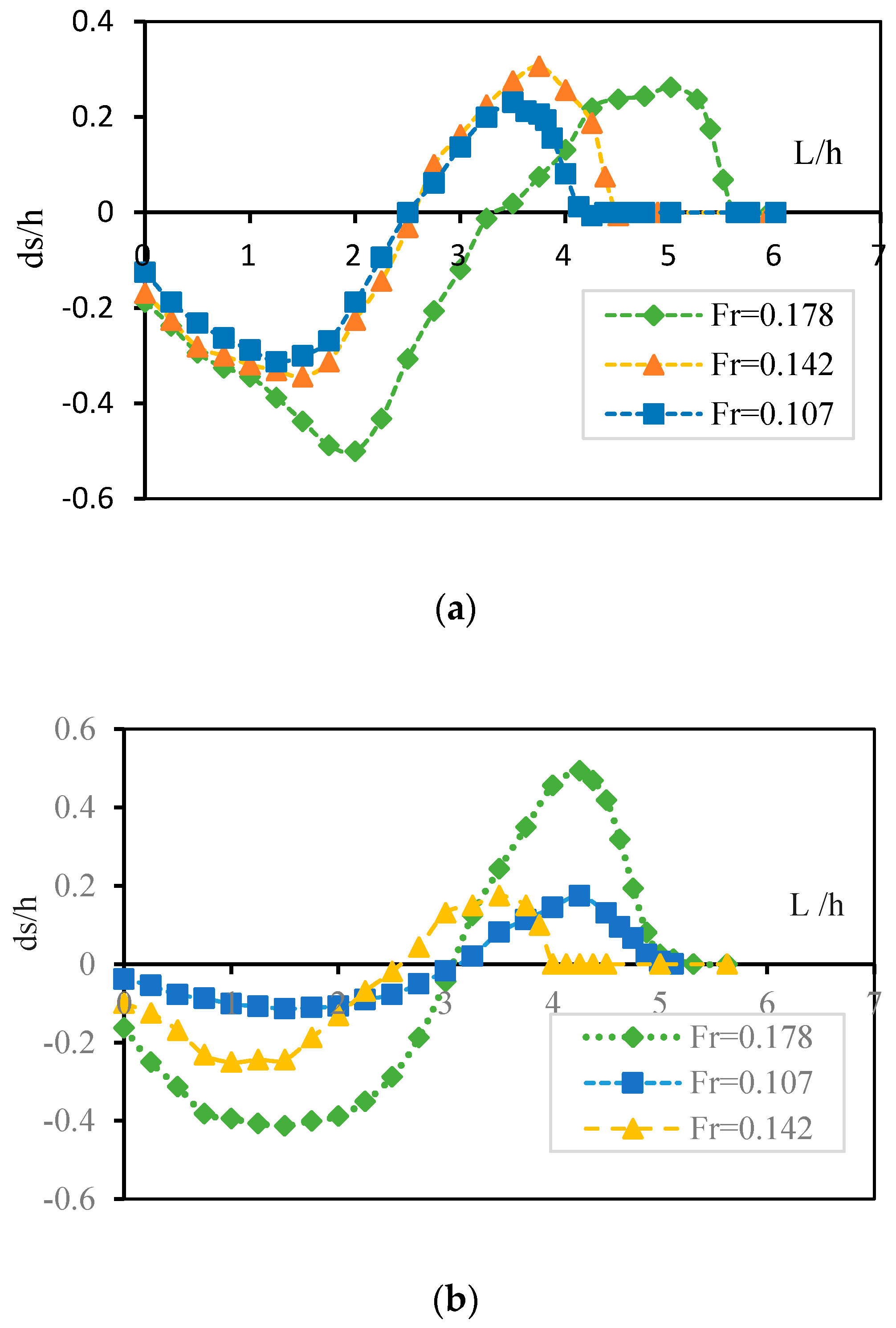
Figure 6.
Comparison of the longitudinal profile of the bed for Run 10, Run 18, and Run 30: (a) y/W = 0.25 (left side); (b) y/W = 0.75 (right side).
Figure 6.
Comparison of the longitudinal profile of the bed for Run 10, Run 18, and Run 30: (a) y/W = 0.25 (left side); (b) y/W = 0.75 (right side).
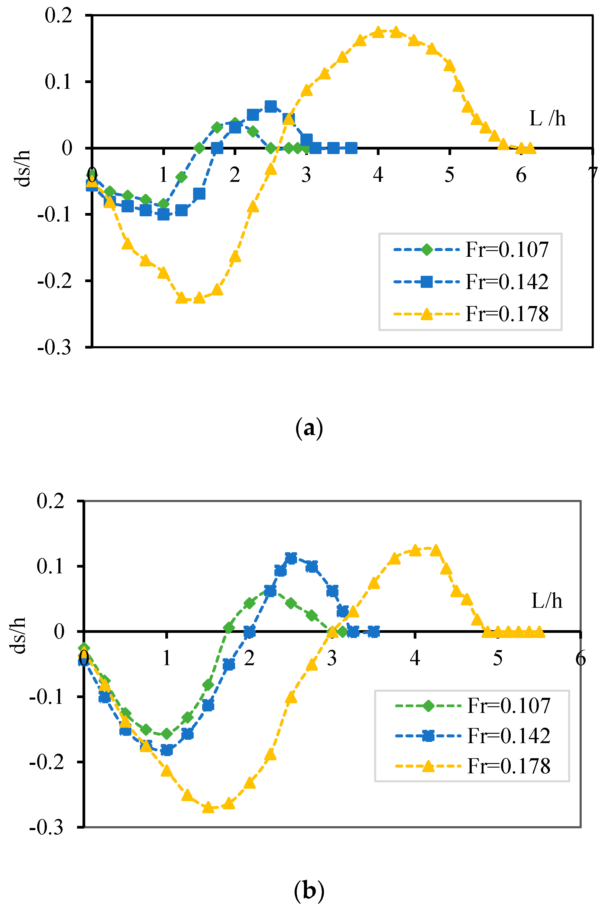
Figure 7.
Comparison of the longitudinal profile of the bed for Run 2, Run 14, and Run 26: (a) y/W = 0.25 (left side); (b) y/W = 0.75 (right side).
Figure 7.
Comparison of the longitudinal profile of the bed for Run 2, Run 14, and Run 26: (a) y/W = 0.25 (left side); (b) y/W = 0.75 (right side).


Table 1.
Past experimental studies on weirs.
| Reference | Flume Dimension (m) | Sediment Info. | Type of Structure | Discharge Rate (L/s) | Investigated Scour Properties |
|---|---|---|---|---|---|
| Bhuiyan et al. [16] | FL: 14.96 m FW:1.6 m FS: 0.00133 SC: 1.38 | d50 = 1.5 mm | W-weir | 97, 164 | - Turbulence characteristic - Sediment transport - Scour development |
| Bhuiyan et al. [17] | FL: 14.96 m FW:1.6 m FS: 0.00133 SC: 1.38 | d15 = 0.95 mm d50 = 1.5 mm d90 = 3.2 mm | 1. W-weir 2. Vane | 97, 164 | - Flow pattern - Bed adjustment - Sediment transport - Scour after installed structures |
| Scurlock et al. [19] | FL: 15.24 m FW: 4.88 m FH: 1.22 m | d50 = 4.2–15.38 mm | 1. A-weir 2. U-weir 3. W-weir | 0.184 to 1.133 | - Maximum scour depth - Evaluation scour - Prediction methodology |
| Pagliara and Kurdistani [26] | FL: 7 m FW: 0.342 m | d50 = 3.52 mm Gs = 1.29 | 1. I-weir 2. U-weir | 2, 3, 4, 5 | - The shape of the structure - Scour hole width - Location of the maximum scour |
| Pagliara et al. [20] | FL: 20 m FW: 0.8 m FH: 0.75 m | d50 = 1.6 mm Gs = 2.6 σg = 1.26 | W-weir | 5, 7, 10, 25, 50 | - Scour development patterns - Location of maximum scour - Maximum ridge height and length - Maximum scour depth |
| Pagliara and Kurdistani [27] | FL: 20 m FW: 0.8 m FH: 0.75 m | d50 = 1.7 mm Gs = 2.6 σg = 1.16 | 1. Log vane 2. J-hook vane | – | - Scour parameters for different combinations and hydraulic conditions downstream of log-vanes and J-hook vanes |
| Bahrami Yarahmadi and Shafai Bejestan [22] | FW: 0.7 m R/B: 4 FH: 1.22 m | d50 = 1.5 mm σg = 1.22 | Vane | 25, 27, 30, 33 | - Flow pattern with and without vanes - Scouring and deposition - Maximum scour depth downstream of the vane. - Effective of variations in space between vanes |
| Kurdustani and Pagliara [25] | FL: 156.7 m FW: 0.5 m FH: 0.5 m | d50 =1.77 mm Gs = 2.6 σg = 1.26 | Cross vane | – | - Effect of channel bend radius on the scour - Scour morphology - Maximum scour hole - Structure orientation with respect to the flow direction |
| Present study | FL: 6.7 m FW: 0.35 m FH: 0.5 m SC: 1.12 | d50 = 1.5 mm σg = 1.21 | W-weir | 7.5, 10, 12.5 | - Maximum scour depth downstream of W-weir - The volume of the scour hole (length and width) - Height of W-weir - Optimize of the inner angle of the weir |
Notes: FL: Flume Length, FW: Flume Width, FH: Flume Height, FS: Flume Slope, SC: Sinuosity of Channel, R/B: the ratio of the curvature’s radius to the flume’s width.
Table 2.
List of the experiments carried out in the present study.
| Test Name | Q (m3/s) | Fr | τb | u* | Ro | Ho/h | θ | V (cm3) | Scour Type |
|---|---|---|---|---|---|---|---|---|---|
| Run 1 | 0.0075 | 0.107 | 0.211 | 0.0145 | 4.13 | 0.5 | 50 | 176 | B |
| Run 2 | 0.0075 | 0.107 | 0.211 | 0.0145 | 4.13 | 0.5 | 64 | 123 | B |
| Run 3 | 0.0075 | 0.107 | 0.211 | 0.0145 | 4.13 | 0.5 | 86 | 174 | B |
| Run 4 | 0.0075 | 0.107 | 0.211 | 0.0145 | 4.13 | 0.5 | 124 | 163 | C |
| Run 5 | 0.0075 | 0.107 | 0.211 | 0.0145 | 4.13 | 1 | 50 | 1386 | B |
| Run 6 | 0.0075 | 0.107 | 0.211 | 0.0145 | 4.13 | 1 | 64 | 603 | B |
| Run 7 | 0.0075 | 0.107 | 0.211 | 0.0145 | 4.13 | 1 | 86 | 677 | B |
| Run 8 | 0.0075 | 0.107 | 0.211 | 0.0145 | 4.13 | 1 | 124 | 750 | C |
| Run 9 | 0.0075 | 0.107 | 0.211 | 0.0145 | 4.13 | 1.5 | 50 | 3575 | B |
| Run 10 | 0.0075 | 0.107 | 0.211 | 0.0145 | 4.13 | 1.5 | 64 | 3027 | B |
| Run 11 | 0.0075 | 0.107 | 0.211 | 0.0145 | 4.13 | 1.5 | 86 | 3123 | C |
| Run 12 | 0.0075 | 0.107 | 0.211 | 0.0145 | 4.13 | 1.5 | 124 | 3774 | C |
| Run 13 | 0.010 | 0.142 | 0.364 | 0.0191 | 3.27 | 0.5 | 50 | 512 | B |
| Run 14 | 0.010 | 0.142 | 0.364 | 0.0191 | 3.27 | 0.5 | 64 | 426 | B |
| Run 15 | 0.010 | 0.142 | 0.364 | 0.0191 | 3.27 | 0.5 | 86 | 745 | B |
| Run 16 | 0.010 | 0.142 | 0.364 | 0.0191 | 3.27 | 0.5 | 124 | 756 | C |
| Run 17 | 0.010 | 0.142 | 0.364 | 0.0191 | 3.27 | 1 | 50 | 2525 | B |
| Run 18 | 0.010 | 0.142 | 0.364 | 0.0191 | 3.27 | 1 | 64 | 1148 | B |
| Run 19 | 0.010 | 0.142 | 0.364 | 0.0191 | 3.27 | 1 | 86 | 1920 | B |
| Run 20 | 0.010 | 0.142 | 0.364 | 0.0191 | 3.27 | 1 | 124 | 1827 | C |
| Run 21 | 0.010 | 0.142 | 0.364 | 0.0191 | 3.27 | 1.5 | 50 | 6343 | B |
| Run 22 | 0.010 | 0.142 | 0.364 | 0.0191 | 3.27 | 1.5 | 64 | 5599 | B |
| Run 23 | 0.010 | 0.142 | 0.364 | 0.0191 | 3.27 | 1.5 | 86 | 6525 | C |
| Run 24 | 0.010 | 0.142 | 0.364 | 0.0191 | 3.27 | 1.5 | 124 | 8911 | C |
| Run 25 | 0.0125 | 0.178 | 0.571 | 0.02391 | 2.51 | 0.5 | 50 | 943 | B |
| Run 26 | 0.0125 | 0.178 | 0.571 | 0.02391 | 2.51 | 0.5 | 64 | 859 | B |
| Run 27 | 0.0125 | 0.178 | 0.571 | 0.02391 | 2.51 | 0.5 | 86 | 1128 | B |
| Run 28 | 0.0125 | 0.178 | 0.571 | 0.02391 | 2.51 | 0.5 | 124 | 1900 | C |
| Run 29 | 0.0125 | 0.178 | 0.571 | 0.02391 | 2.51 | 1 | 50 | 5365 | B |
| Run 30 | 0.0125 | 0.178 | 0.571 | 0.02391 | 2.51 | 1 | 64 | 3231 | B |
| Run 31 | 0.0125 | 0.178 | 0.571 | 0.02391 | 2.51 | 1 | 86 | 4160 | B |
| Run 32 | 0.0125 | 0.178 | 0.571 | 0.02391 | 2.51 | 1 | 124 | 4687 | C |
| Run 33 | 0.0125 | 0.178 | 0.571 | 0.02391 | 2.51 | 1.5 | 50 | 8308 | B |
| Run 34 | 0.0125 | 0.178 | 0.571 | 0.02391 | 2.51 | 1.5 | 64 | 7404 | B |
| Run 35 | 0.0125 | 0.178 | 0.571 | 0.02391 | 2.51 | 1.5 | 86 | 10,692 | C |
| Run 36 | 0.0125 | 0.178 | 0.571 | 0.02391 | 2.51 | 1.5 | 124 | 13,216 | C |
.
Table 3.
Description angle of the inner arms.
| Plan View of Weir | θ | Lo/Li |
|---|---|---|
 | 50 | 1 |
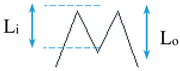 | 64 | 3/4 |
 | 86 | 1/2 |
 | 124 | 1/4 |
© 2017 by the authors. Licensee MDPI, Basel, Switzerland. This article is an open access article distributed under the terms and conditions of the Creative Commons Attribution (CC BY) license (http://creativecommons.org/licenses/by/4.0/).
Share and Cite
MDPI and ACS Style
Abdollahpour, M.; Hosseinzadeh Dalir, A.; Farsadizadeh, D.; Gualtieri, C. Experimental Study on Erosion and Sedimentation Patterns Downstream of a W-weir in a Sinusoidal Mild Bend. Water 2017, 9, 638. https://doi.org/10.3390/w9090638
AMA Style
Abdollahpour M, Hosseinzadeh Dalir A, Farsadizadeh D, Gualtieri C. Experimental Study on Erosion and Sedimentation Patterns Downstream of a W-weir in a Sinusoidal Mild Bend. Water. 2017; 9(9):638. https://doi.org/10.3390/w9090638
Chicago/Turabian StyleAbdollahpour, Milad, Ali Hosseinzadeh Dalir, Davod Farsadizadeh, and Carlo Gualtieri. 2017. "Experimental Study on Erosion and Sedimentation Patterns Downstream of a W-weir in a Sinusoidal Mild Bend" Water 9, no. 9: 638. https://doi.org/10.3390/w9090638
Note that from the first issue of 2016, this journal uses article numbers instead of page numbers. See further details here.