Design and Analysis of a Plate Type Electrodynamic Suspension Structure for Ground High Speed Systems


1
Maglev Research Center, College of Intelligence Science and Technology, National University of Defense Technology, Changsha 410073, China
2
State Key Laboratory of Functional Materials for Informatics, Shanghai Institute of Microsystem and Information Technology, Chinese Academy of Sciences, Shanghai 200050, China
*
Author to whom correspondence should be addressed.
Symmetry 2019, 11(9), 1117; https://doi.org/10.3390/sym11091117
Submission received: 8 July 2019
/
Revised: 21 August 2019
/
Accepted: 29 August 2019
/
Published: 4 September 2019
(This article belongs to the Special Issue Symmetry in Electromagnetism)
Abstract
:The research of ground high speed systems has been popular, especially after the announcement of Hyperloop concept, and the analysis of the suspension structure is critical for the design of the system. This paper focuses on the design and analysis of a plate type electrodynamic suspension (EDS) structure for the ground high speed system. The working principle of proposed whole system with functions of levitation, guidance and propulsion is presented, and the researched EDS structure is composed of permanent magnets (or superconducting magnets) and non-ferromagnetic conductive plates. Levitation and guidance are achieved by forces generated through the motion of the magnets along the plates. The plate type EDS structure is analyzed by three-dimensional (3D) finite element method (FEM) in ANSYS Maxwell. Structure parameters that affect the EDS performances are investigated, which include dimensions of magnets and plates, plate material, the relative position between magnets and plates, and arrangement of magnets. The properties of forces are discussed, especially for the levitation force, and the levitation working point is decided based on the analysis. Levitation-drag ratio of the plate type structure is investigated, and it improves with the increasing of vehicle velocity. The analysis results indicate that the plate type EDS structure is feasible for applications in ground high speed systems. The following study will focus on the dynamic research of the EDS system.
1. Introduction
Nowadays, the research of ground high speed systems including high speed train and super speed test sled has been popular with the increasing demand for higher speed. For example, Elon Musk presented the concept of Hyperloop in 2013 and the Evacuated Tube Transportation (ETT) has received much attention from research institutes and the transportation industry [1,2]. Compared with wheel-rail structure, contactless design is expected to be adopted in ground high speed systems to minimize frictions, vibrations and noises during the operation. Magnetic levitation (maglev) is the most widely studied contactless technology and the maglev train is a well-known application. The maglev train has a different working principle from conventional wheel-rail train driving forward by frictions, as it achieves levitation through interaction between the magnets aboard and the rails and produces propulsion force electromechanically without contact with the rails [3].
The Electrodynamic Suspension (EDS) repulsion system and the Electromagnetic Suspension (EMS) attraction systems are two main kinds of maglev systems [4]. The EDS system achieves levitation by the electromagnetic repulsive force between the magnet and the non-ferromagnetic conductive rail. The relative motion of the magnet along the rail will induce eddy current in the ground conductor, and according to Lenz law, the magnetic field induced by the eddy current will oppose the magnetic field from the aboard magnet to generate repulsive force [5]. When the moving vehicle reaches a certain speed, the repulsive force increases enough to levitate the train. Thus, the EDS structure does not need active control and is an essential open-loop stable system [6]. Superconducting (SC) magnet and permanent magnet (PM) are two excitation sources applied in EDS system, and there are two kinds of EDS rails: continuous conductive plate and discrete metal coil. The Holloman High Speed Test Track (after maglev update) is a typical continuous EDS structure with copper plates embedded in the guideway, and the SC magnets aboard interact with the plates to provide levitation and guidance forces through relative motion [7]. The sled is propelled by solid fuel rocket motors, and the test speed reached 673 km/h in 2008. However, the rocket motor is expensive and cannot be reused, and it is hard to adjust the running speed during operation. The publications about Holloman High Speed Test Track are few and about the program update and some flight test results without critical characteristics analysis mentioned. A representative of typical discrete EDS system is the SC maglev train of JR Company in Japan, which adopts figure-eight null flux coils to achieve a high levitation-drag ratio [8]. The levitation coil and the propulsion coil are at the same side of the SC magnet, and the ground transportation speed record of 603 km/h was made by the SC maglev train on the Yamanashi Line in 2015. Unlike the EDS system, electromagnet is adopted in EMS structure to interact with the ferromagnetic rail to generate attractive electromagnetic force. EMS is an open-loop unstable system and active control of currents in the electromagnet is needed to achieve levitation at the expected gap [9,10]. Now, the top operation speed of EMS train is 430 km/h from the TR train on Shanghai maglev line [11].
EMS and EDS both have advantages in the application. Through active control of currents in the electromagnet, accurate levitation gap could be realized in EMS system and the dynamic performance during operation is adjustable. However, the electromagnet is heavy and the ancillary equipment, such as power supply, signal detection, and control systems, make the whole structure complex. Additionally the operation of high speed will make the conduction of real-time control difficult. Another problem is the obvious eddy current in the steel rail at high speeds [12,13], which will reduce the levitation force and lead to increasing currents and heat in the electromagnet. Compared with EMS, EDS has been attracting more attention in the research of ground high speed systems. The design and analysis of a Hyperloop structure including levitation and propulsion control system was conducted by Abdelrahman et al. [14], and null flux coil structure was adopted. An all-in-one system containing functions of levitation, propulsion and guidance was presented by Ji et al., and conductive plate EDS structure was adopted in the design [15]. A high-temperature superconducting EDS system used in the high speed maglev train was studied by Hao et al.; a mirror method was proposed for calculating and the accuracy was verified by the FEM model [16].
This paper focuses on the design and analysis of a plate type EDS structure for ground high speed systems. Since fluctuation of electrodynamic forces in coil type EDS structure is obvious due to discrete arrangement of coils [17] and the manufacture of coils is relatively complex, conductive plate rails are adopted to interact with aboard moving magnets to provide levitation and guidance. Meanwhile, magnetic fields from the other side of the magnets are used for propulsion, which could simplify the whole system. The EDS structure is analyzed by finite element method, and parameters of magnets and plates that affect the EDS performance are investigated. The forces properties at constant speeds are analyzed and the analysis results have shown that the researched plate type EDS structure is promising for application in the ground high speed systems.
2. Proposed Ground High Speed System
The designed ground high speed structure is composed of two subsystems, levitation system and propulsion system, as shown in Figure 1. Axis X is the lateral direction, axis Y is the vehicle moving direction, and axis Z is the vertical direction where the vehicle is levitated. The vehicle body is mounted upon the propulsion stator and magnets are placed on both lateral sides of the vehicle. SC magnet and PM can be adopted as excitation source in the design, and PM is selected in this paper. Non-ferromagnetic metal plates (copper plates or aluminum plates) are embedded in the lateral symmetrical guideway beams, and the supporting structures including beams and buttress are made of non-metallic material to avoid effect on propulsion and levitation. When the magnet aboard moves along the rails, eddy current is induced in the plates and the interaction between the magnet and the eddy current will generate levitation, guidance and drag forces. The double plate (upper and lower) structure is adopted and the center-line of the magnets is lower than that of the double plates in axis Z. The overlap area between the magnet and the lower plate is larger than the one with the upper plate, and the resultant on the magnet in axis Z will be upward levitation force. The linear synchronous motor contains the magnet mover and the long hollow stator coils. It can be seen that both sides of magnets are used in the system to get high utilization of magnetic fields and simplify the whole structure. Traveling wave magnetic fields are generated by flowing three-phase AC in the hollow stator coils, and the magnetic fields interact with the magnet aboard to achieve electromagnetic thrust and synchronous motion. The deceleration is conducted by reversing the direction of the stator currents to produce braking forces, and the drag forces from metal plates could also make a part of contribution.
3. Analysis of the Plate Type EDS Structure
The double plate structure could be divided to two single plates, and the magnetic forces acting on the magnet are the resultant of component forces from single plates. It is reasonable to analyze properties of the single plate structure for simplicity, and the side view of the single plate structure is shown in Figure 2.
According to the Ampere circuital theorem, the relationship between the induced current density J and the magnetic flux density B in the plate can be described as:
Then:
Based on Lorentz law, the levitation, drag and guidance forces between the plate and the magnet are:
where is the integral domain in the plate and is the permeability of the plate. The magnetic field and force equations are complex to solve, and approximations are usually involved in the derivation [18,19,20]. The analytical approach has its limited applicability in the initial design of the plate type EDS structure, and finite element simulation (FEM) using ANSYS Maxwell is adopted to study the characteristics of the EDS magnetic forces. The parameters of proposed EDS structure for FEM simulation are listed in Table 1, which are adopted in the construction of a prototype platform for test. The mesh plot of the simulation model in ANSYS and the pole pith of the two magnets are shown in Figure 3, and the following analysis is on the constant speed in axis Y without electrodynamic terms in axes X and Z.
3.1. Levitation Working Point
The height difference h is an important parameter in the EDS structure, and it can be regarded as the working point of levitation. The simulation is conducted at the speed of 10 m/s, and the results of three forces are shown in Figure 4. The guidance and the drag forces have the same trend. The values decrease with the increasing of the height difference h, and this can be explained by the change of overlap area between the magnet and the plate in qualitative analysis. However, the levitation force is different from the other two. At small values of h, the levitation force increases with the growing of the height difference h. It reaches the top value at around 60 mm, and then stays relatively constant for a range of values. Then, with the further increase of h, the levitation force will decrease as the other two forces. The trend of levitation force could also be explained qualitatively. When h = 0, the magnet and the plate are mid-lines coincided, the levitation force is 0 due to symmetry. With the increasing of h, the symmetry is destroyed and the levitation force appears and increases. Then, with the further increasing of h at a large value, the interaction between the magnet and the plate will be very weak and the forces will all be zero in the end.
The levitation-drag ratio is shown in Figure 5, and it grows with the increase of h. The height difference h is set to 70 mm (about 1/3 of magnet height 200 mm) to provide adequate levitation force, as listed in Table 1. However, the levitation force around the working point changes little, and the system could not provide sufficient levitation stiffness at current setting. Because the PM is unable to generate strong enough magnetic fields, the working point cannot be set in the domain with large height differences (such as around 110 mm in Figure 4). Thus, the height difference h can be set around point of 1/3 height of magnet to provide enough levitation force when PM is used, and the working point can be moved to a larger h beyond 1/3 height of magnet to achieve stronger levitation stiffness if SC magnet is adopted in the system.
3.2. Guidance Stiffness
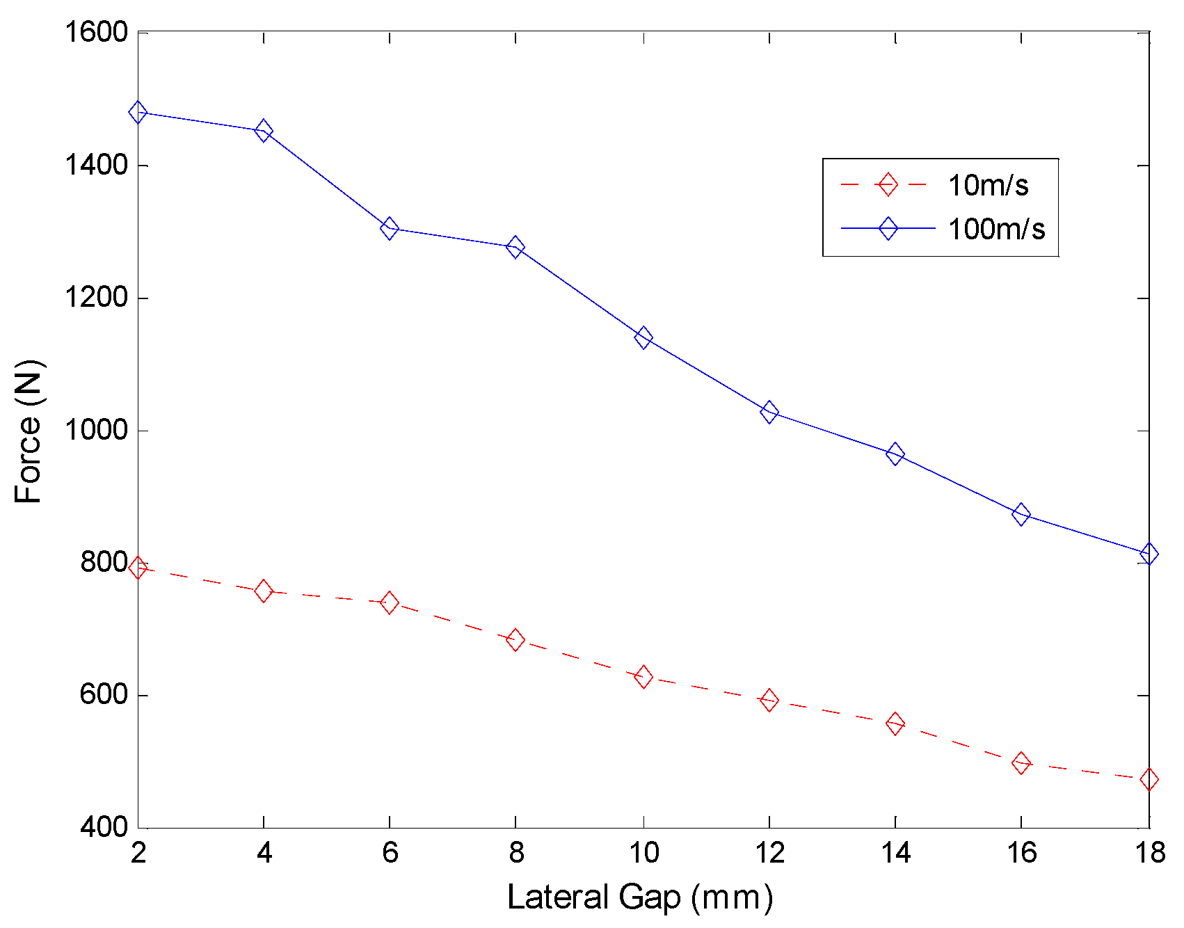
Guidance stiffness is an important performance index in the maglev system, which is related with lateral stability. The guidance stiffness of the system can be studied by changing the gap G between the magnet and the plate at speeds of 10 m/s and 100 m/s, respectively. The guidance force results are shown in Figure 6. The value of G is set to 10 mm in the system as shown in Table 1. When the gap from one side of the vehicle body moves to 8 mm, then the gap value on the other side will be 12 mm. The guidance force on the vehicle from both sides of plates will be , and the guidance stiffness 23 N/mm is calculated at the speed of 10 m/s. Similarly the guidance force and the stiffness at the speed of 100 m/s are 249 N and 62 N/mm, respectively. The stiffness at low speeds is relatively insufficient compared with that at a high speed, and guidance wheels could be designed in the EDS structure.
3.3. Effects of Speed
Since the EDS force is based on the relative motion between the magnet and the plate, it is essential to research the effects of vehicle speed on magnetic forces. The forces in three axes at different velocities with the structure parameters in Table 1 are shown in Figure 7. The performances of copper and aluminum plates are compared in the simulation.
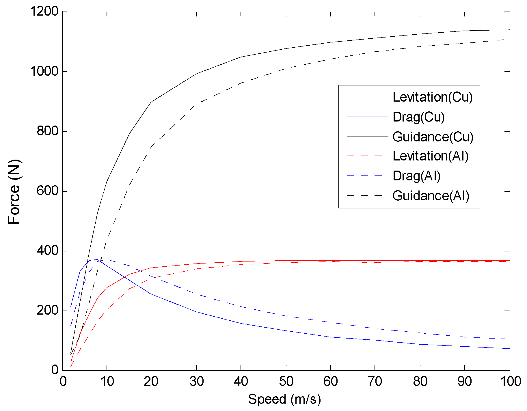
The results show that the levitation force and the guidance force increase with magnet velocity at initial low speeds; then, they will stay relatively constant when reaching high speeds. This is beneficial for the super speed system that the system can be steadily levitated on the set height at speeds beyond the critical point, and the constant guidance force will not heighten the demand on structural strength of the vehicle body. The performance of drag force is different from the other two forces. It increases at the initial low speeds and after reaching the peak value, the force decreases with the increasing of magnet speed. Thus, the ratio of the levitation force and the drag force becomes higher at relative high velocities, as shown in Figure 8, which is beneficial for application in the ground high speed system. Additionally, it can be seen that the EDS structure with copper plate could provide better levitation-drag ratio than aluminum plate.
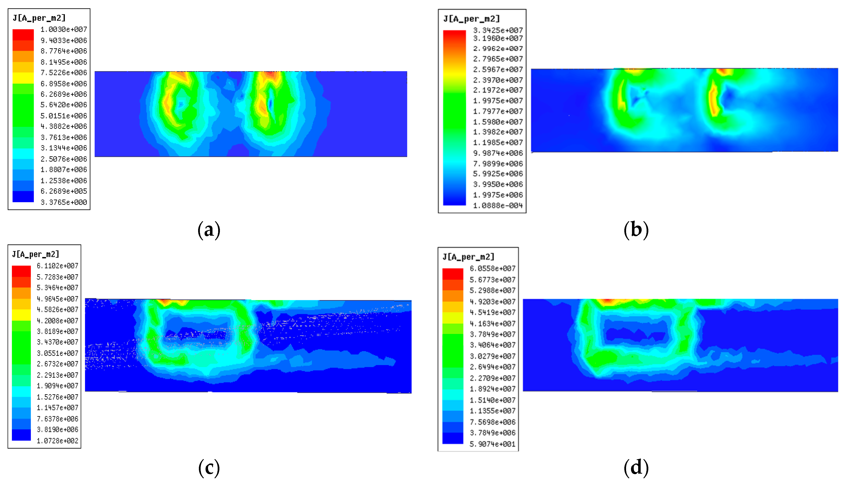
Magnetic forces are generated by reactions between the magnets and the eddy currents in the plates. It is essential to study the eddy current property, and the eddy current distributions on the plate surface at different vehicle speeds are shown in Figure 9. To make the analysis easier to understand, only one permanent magnet is adopted here and the principles are same for NS poles arranged magnets. In the simulation models, the magnets move from right to left and the rainbow color presents the magnitude of induced eddy current densities. It can be seen that the maximum value of eddy current on the plate becomes larger with the increasing of speed at first (for example from 2 m/s to 10 m/s) and then will stay almost constant at high speeds (for example at 70 m/s and 100 m/s). The simplified illustration of interaction between the magnet and the plate with single magnet in cross-section view is shown in Figure 10.
At low speeds, there exist two symmetric vortices of eddy current distributions. From the Lenz law, the current flow directions are opposite in the two vortices as illustrated in Figure 10a and the interactions between both vortices and the magnet perform as drag force in the moving direction. With the increasing of magnet speed, the back vortex will be pushed and reduced. Thus, there will be only one vortex with perfect same shape as the magnet as shown in Figure 9c,d at high speeds. It can be seen from Figure 10b that the drag force will be greatly reduced and the levitation-drag ratio will improve obviously.
3.4. Magnet Design
3.4.1. Distribution of Magnetic Field
PM and SC magnet are two main magnets adopted in the EDS system. Although permanent magnet is adopted in this analysis, it is important to study the magnetic field distributions of both magnets. The parameters of both magnets for comparison are listed in Table 2, and they have the same shape and size.
The rainbows of magnetic field vector from both magnets are shown in Figure 11, and the amplitudes of magnetic flux density at the mid-lines in Y and Z directions 10 mm away from the surface of magnets are plotted in Figure 12. It can be seen that the distribution tendencies of magnetic fields from PM and SC magnet are basically same. The magnetic fields near the borders of magnets are strongest and will decrease apart from the borders. The same distributions could indicate that the analysis results of PM are also appropriate for SC magnet, and the difference is that the SC could provide much stronger magnetic fields through adjusting the flowing currents in the SC coils.
3.4.2. Magnet Thickness
The height and the pole length of the permanent magnets are decided by the design of the propulsion, which is not involved here. The magnet pole face is 23 cm × 20 cm, the remanence of the NdFeB magnet is 1.3 T and the coercivity is 940 kA/m. Magnetic flux densities of the center point on the magnet surface are illustrated in Figure 13. As can be seen, although the magnetic flux density strengthens with increasing magnet thickness, the increment becomes gentle with the increasing of the thickness. Considering the manufacture and the magnet weight, it is not a good idea to get strong magnetic field through increasing the magnet thickness and 20 mm is selected as listed in Table 1.
3.4.3. Magnet Length
The effects of different magnet lengths on levitation force are researched. The pole length of the permanent magnets is 270 mm, which is decided from the propulsion calculation. The results are shown in Table 3, and the speed is 10 m/s. Although levitation force becomes larger with the increase of magnet length, the increment is narrow when the magnet length approaches the pole length. Furthermore, the long and large permanent magnet is fragile and difficult to manufacture, thus a 230 mm long magnet was selected in the design.
3.4.4. Magnet Arrangement
Although the magnets are alternately arranged in magnetic N and S poles for propulsion in the proposed system as shown in Figure 3, it is still helpful to research the influence of magnet arrangement on magnetic forces, especially the levitation force. Three kinds of magnet arrangements are studied: single magnet, same pole arranged magnets (such as NN), and NS poles arranged magnets (shown in Figure 3); the results are shown in Figure 14. Double value of single magnet arrangement is included to be as a reference.
It can be seen that the levitation force value of NS arranged magnets is larger than the double value of single magnet, and the value of NN arranged magnets is smaller than the double one. This can be explained in qualitative analysis. For the NN arranged magnets, the change rate of magnetic field generated by the back N pole magnet in conductive plate is gentler than the one by the front magnet. According to Lenz law, the back magnet will generate weaker induced voltage and eddy current, which will make the levitation force of NN arranged magnets smaller than the double value of single magnet. However, the change rate of magnetic field generated by the back magnet in conductive plate is more dramatic than the one by the front magnet. Then, the back magnet will generate stronger induced voltage and eddy current, which will make the levitation force of NS arranged magnets larger than the double value of single magnet. The eddy current distributions of NN and NS arranged magnets at speeds of 10 m/s and 100 m/s are shown in Figure 15. It is obvious that the NS arranged magnets could induce stronger eddy currents than NN arranged magnets, which has verified the explanation. From the above analysis, we can also get that there exist difference between the two forces from the front and the back magnets, and this will be studied in the following.
3.5. Plate Design
3.5.1. Plate Materials
In the proposed EDS structure, the plate should be non-ferromagnetic conductive. Two common materials copper and aluminum are separately studied, whose conductivities are 58 MS/m and 38 MS/m, respectively. The comparisons of forces and levitation-drag ratios are shown in Figure 7 and Figure 8, respectively. The levitation force and the guidance force from the copper plate increase faster than that from the aluminum plate at low speeds, but the difference becomes minor when the magnet speed is high and the forces tend to be the same. The drag force from the copper plate is larger than the aluminum one at the initial low speeds, and after the peak value it decreases faster than the aluminum one. Levitation-drag ratio is an important index, and from Figure 8, the EDS structure with copper plate could provide a higher levitation-drag ratio than aluminum plate.
3.5.2. Plate Height
Plate height is an important factor that will influence the interaction area between the magnet and the plate. The simulation results of different plate heights with constant height difference h 70 mm at speed of 10 m/s are shown in Figure 16. The forces in three directions including levitation drag and guidance grow with the increasing of plate height, and the guidance force increases fastest. Considering high plate will bring large drag force and high construction cost, 200 mm (the same height with PM) is adopted in the system design.
3.5.3. Plate Thickness
Plate thickness is another important parameter to be designed in the plate type EDS structure. Because of the skin effect at high speeds, the analysis is selected at speed of 100 m/s. The three forces and levitation-drag ratio are shown in Figure 17. It can be seen that the levitation and the guidance forces become larger with the increasing of thickness at first and will stay constant, and the drag force decreases with the increasing of thickness and the change becomes mild at relatively large thickness. Thus, the levitation-drag ration improves with the increasing of plate thickness. Considering the construction cost, 8 mm is selected in the system design.
3.6. Distribution of Levitation Forces on NS Magnets
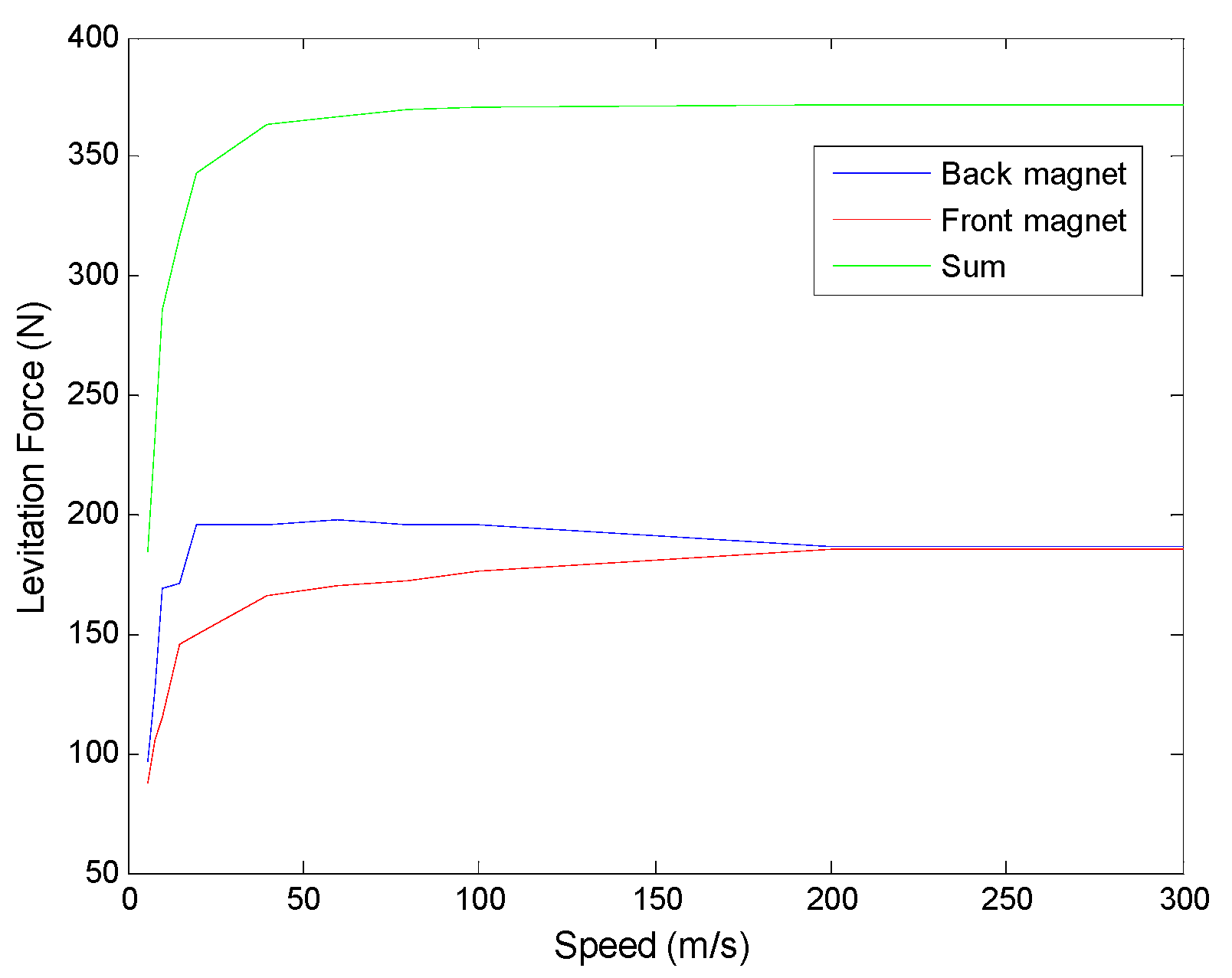
In the above analysis in Section 3.4.4, it is explained that there is difference between the levitation forces of the front magnet and the back magnet in the NS arranged magnets. This is important to research, since the uneven distribution of levitation forces will lead to imbalance of vehicle during operation. The comparison of levitation forces of the front and the back magnets at different speeds are shown in Figure 18. The levitation force from the back magnet increases faster than that from the front magnet at the low speeds, and then it decreases slightly until the two forces are same value. The non-uniform distribution of levitation forces on NS magnets during the vehicle operation is obvious when the vehicle is at a low or middle speed, which indicates a higher standard for the vehicle design.
4. Conclusions
A plate type EDS structure proposed for ground high speed systems is analyzed in this paper. The ground high speed system is integrated with functions of levitation, propulsion and guidance, and the EDS structure is composed of non-ferromagnetic conductive plate and PM (or SC magnet). The designed plate type EDS structure is researched by FEM simulations, and characteristics of the EDS structure are analyzed based on the results.
- The levitation working point is better to be set around 1/3 height of PM to get enough levitation force, and it can be moved to a larger h when SC magnet is applied in the design.
- The lateral stiffness at low speeds is relatively insufficient compared with that at high speeds, and guidance wheels can be adopted.
- The effects of different speeds on magnetic forces are studied and the levitation-drag ratio improves with the increasing of magnets speed.
- PM and SC magnet have the same distribution of magnetic field, and the proper thickness and length of magnet are set. NS arranged magnets show better performance than NN arranged magnets.
- Copper plate could provide larger levitation force and higher levitation-drag ratio than aluminum plate. Proper height and thickness of plate are decided based on the performance and the construction cost.
- The non-uniform distribution of levitation forces on NS magnets will disappear at high speeds.
The results show that the proposed EDS structure is a promising option for application in ground high speed systems. Future research will focus on the study of dynamics properties of the plate type EDS structure, especially the under-damped characteristics of EDS structure during operation.
Author Contributions
Conceptualization, Z.G. and J.L.; methodology, D.Z.; software, Z.G.; formal analysis, Q.C.; investigation, P.Y.; writing—original draft preparation, Z.G.; writing—review and editing, D.Z.; supervision, J.L.; project administration, J.L.
Funding
This research was supported by the National Key R&D Program of China (No. 2016YFB1200601), and the Opening Foundation of the State Key Laboratory of Functional Materials for Informatics (No. SKL-2017-07).
Conflicts of Interest
The authors declare no conflict of interest.
References
- Palacin, R. Hyperloop, the electrification of mobility, and the future of rail travel. IEEE Electr. Mag. 2016, 4, 4–51. [Google Scholar] [CrossRef]
- Hyperloop Alpha. Available online: http://www.spacex.com/hyperloopalpha (accessed on 12 August 2013).
- Lee, H.W.; Kim, K.C.; Lee, J. Review of maglev train technologies. IEEE Trans. Magn. 2006, 42, 1917–1925. [Google Scholar] [CrossRef]
- Yan, L. Development and application of the maglev transportation system. IEEE Trans. Appl. Supercond. 2008, 18, 92–99. [Google Scholar] [CrossRef]
- Davey, K. Analysis of an electrodynamic Maglev system. IEEE Trans. Magn. 1999, 35, 4259–4267. [Google Scholar] [CrossRef]
- Long, Z.; He, G.; Xue, S. Study of EDS & EMS hybrid suspension system with permanent-magnet halbach array. IEEE Trans. Magn. 2011, 47, 4717–4724. [Google Scholar] [CrossRef]
- Hsu, Y.H.; Langhom, A.; Ketchen, D.; Holland, L.; Minto, D.; Doll, D. Magnetic levitation upgrade to the Holloman High Speed Test Track. IEEE Trans. Appl. Supercond. 2009, 19, 2074–2077. [Google Scholar] [CrossRef]
- Okubo, T.; Ueda, N.; Ohashi, S. Effective control method of the active damper system against the multidirectional vibration in the superconducting magnetically levitated bogie. IEEE Trans. Appl. Supercond. 2016, 26. [Google Scholar] [CrossRef]
- Lee, C.Y.; Jo, J.M.; Han, Y.J. Design, fabrication, and operating test of the Prototype HTS electromagnet for EMS-based maglev. IEEE Trans. Appl. Supercond. 2012, 22. [Google Scholar] [CrossRef]
- Xu, J.; Geng, Q.; Li, Y.; Li, J. Design, fabrication and test of an HTS magnetic suspension experimental system. IEEE Trans. Appl. Supercond. 2016, 26. [Google Scholar] [CrossRef]
- Yan, L. Suggestion for selection of Maglev option for Beijing-Shanghai high-speed line. IEEE Trans. Appl. Supercond. 2004, 14, 936–939. [Google Scholar] [CrossRef]
- Du, J.; Ohsaki, H. Numerical analysis of eddy current in the EMS-Maglev system. In Proceedings of the 6th IEEE International Conference on Electrical Machines and Systems, 2003, ICEMS 2003, Beijing, China, 9–11 November 2003; pp. 761–764. [Google Scholar]
- Ding, J.; Yang, X.; Long, Z.; Dang, N. Three dimensional numerical analysis and optimization of electromagnetic suspension system for 200 km/h maglev train considering eddy current effect. IEEE Access. 2018, 6, 1547–1555. [Google Scholar] [CrossRef]
- Abdelrahman, A.S.; Sayeed, J.; Youssef, M.Z. Hyperloop transportation system: Analysis, design, control and implementation. IEEE Trans. Ind. Electron. 2018, 65, 7427–7436. [Google Scholar] [CrossRef]
- Ji, W.Y.; Jeong, G.; Park, C.B.; Jo, I.H.; Lee, H.W. A study of non-symmetric double-sided linear induction motor for Hyperloop all-in-one system (Propulsion, Levitation, and Guidance). IEEE Trans. Magn. 2018, 54. [Google Scholar] [CrossRef]
- Hao, L.; Huang, Z.; Dong, F.; Qiu, D.; Shen, B.; Jin, Z. Study on electrodynamic suspension system with high-temperature superconducting magnets for a high-speed maglev train. IEEE Trans. Appl. Supercond. 2019, 29, 1–5. [Google Scholar] [CrossRef]
- Mulcahy, T.M.; He, J.; Rote, D.M.; Rossing, T.D. Forces on a magnet moving past figure-eight coils. IEEE Trans. Magn. 1993, 29, 2947–2949. [Google Scholar] [CrossRef] [Green Version]
- Knowles, R. Dynamic circuit and Fourier series methods for moment calculation in electrodynamic repulsive magnetic levitation system. IEEE Trans. Magn. 1982, 18, 953–960. [Google Scholar] [CrossRef]
- Lee, J.; Bae, D.K.; Kang, H.; Ahn, M.C.; Lee, Y.; Ko, T.K. Analysis on ground conductor shape and size effect to levitation force in static type EDS simulator. IEEE Trans. Appl. Supercond. 2010, 20, 896–899. [Google Scholar] [CrossRef]
- Ko, W.; Ham, C. A novel approach to analyze the transient dynamics of an electrodynamic suspension maglev. IEEE Trans. Magn. 2007, 43, 2603–2605. [Google Scholar] [CrossRef]
Figure 1.
Proposed structure of ground high speed system.

Figure 2.
Single plate electrodynamic suspension (EDS) structure.

Figure 3.
Mesh plot of the simulation model in ANSYS.

Figure 4.
EDS forces as a function of height difference h (speed 10 m/s).

Figure 5.
Levitation-drag ratio as a function of height difference h at a speed of 10 m/s.

Figure 6.
Guidance force as a function of the gap between the magnet and the plate.

Figure 7.
EDS forces as a function of magnet velocity.

Figure 8.
Levitation drag ratio over magnet velocity.

Figure 9.
Distribution of eddy currents on plate surface at different speeds with single magnet, (a) 2 m/s, (b) 10 m/s, (c) 70 m/s, and (d) 100 m/s.
Figure 9.
Distribution of eddy currents on plate surface at different speeds with single magnet, (a) 2 m/s, (b) 10 m/s, (c) 70 m/s, and (d) 100 m/s.

Figure 10.
Simplified illustration of interaction between the magnet and the plate at different speeds with single magnet in cross-section view: (a) low speed and (b) high speed.
Figure 10.
Simplified illustration of interaction between the magnet and the plate at different speeds with single magnet in cross-section view: (a) low speed and (b) high speed.

Figure 11.
Rainbows of magnetic field vector, (a) PM, (b) SC magnet.
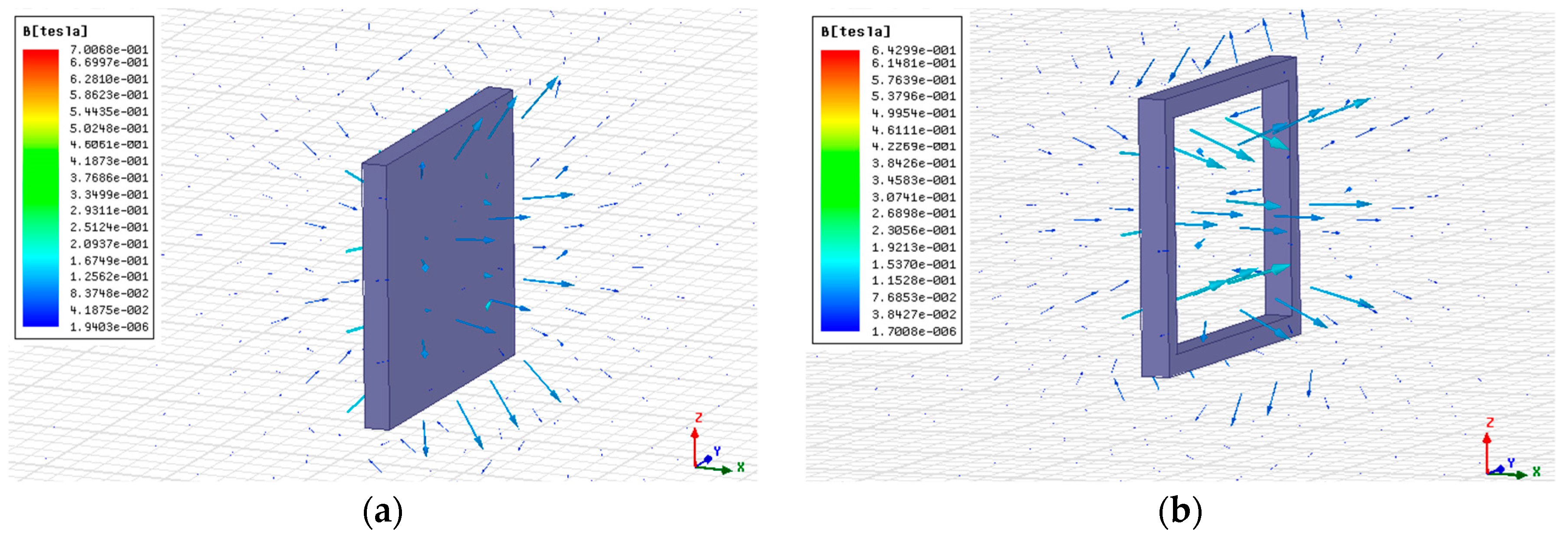
Figure 12.
Distributions of magnetic flux density: (a) Y direction of PM, (b) Z direction of PM, (c) Y direction of SC magnet, and (d) Z direction of SC magnet.
Figure 12.
Distributions of magnetic flux density: (a) Y direction of PM, (b) Z direction of PM, (c) Y direction of SC magnet, and (d) Z direction of SC magnet.

Figure 13.
Magnetic flux density over magnet thickness.

Figure 14.
Levitation forces with different magnet arrangements (NN and NS) over magnet velocity.

Figure 15.
Distribution of eddy currents on plate surface at different speeds with NN and NS arranged magnets: (a) NN magnets at 10 m/s, (b) NS magnets at 10 m/s, (c) NN magnets at 100 m/s, and (d) NS magnets at 100 m/s.
Figure 15.
Distribution of eddy currents on plate surface at different speeds with NN and NS arranged magnets: (a) NN magnets at 10 m/s, (b) NS magnets at 10 m/s, (c) NN magnets at 100 m/s, and (d) NS magnets at 100 m/s.

Figure 16.
Levitation force as a function of plate height.

Figure 17.
Simulation results of different thicknesses of plate at speed of 100 m/s. (a) Levitation, drag, and guidance forces, (b) levitation drag ratio.
Figure 17.
Simulation results of different thicknesses of plate at speed of 100 m/s. (a) Levitation, drag, and guidance forces, (b) levitation drag ratio.

Figure 18.
Simulation results of levitation forces of the front and the back magnets.


Table 1.
Parameters of the FEM model. PM: permanent magnet.
| Variable | Symbol | Value | Unit |
|---|---|---|---|
| Length of magnet (Y axis) | lm | 230 | mm |
| Height of magnet (Z axis) | Hm | 200 | mm |
| Thickness of magnet (X axis) | Tm | 20 | mm |
| Pole pitch of magnets (Y axis) | 270 | mm | |
| Remanence of PM | 1.3 | T | |
| Coercivity of PM | 940 | kA/m | |
| Relative permeability of PM | 1.09 | ||
| Height of plate (Z axis) | Hp | 200 | mm |
| Thickness of plate (X axis) | Tp | 8 | mm |
| Gap between magnet and plate (X axis) | G | 10 | mm |
| Height difference between mid-lines of magnet and plate (Z axis) | h | 70 | mm |
Table 2.
Parameters of both magnets. SC: superconducting.
| Variable | Value | Unit |
|---|---|---|
| Length | 230 | mm |
| Height | 200 | mm |
| Thickness | 20 | mm |
| Remanence of PM | 1.3 | T |
| Coercivity of PM | 940 | kA/m |
| Relative permeability of PM | 1.09 | |
| Current in SC magnet | 18.8 | kA |
Table 3.
Levitation forces with different magnet lengths.
| Magnet Length (mm) | Levitation Force (N) |
|---|---|
| 190 | 230 |
| 200 | 236 |
| 210 | 240 |
| 220 | 256 |
| 230 | 268 |
| 240 | 280 |
| 250 | 288 |
| 260 | 295 |
| 270 | 297 |
© 2019 by the authors. Licensee MDPI, Basel, Switzerland. This article is an open access article distributed under the terms and conditions of the Creative Commons Attribution (CC BY) license (http://creativecommons.org/licenses/by/4.0/).
Share and Cite
MDPI and ACS Style
Guo, Z.; Zhou, D.; Chen, Q.; Yu, P.; Li, J. Design and Analysis of a Plate Type Electrodynamic Suspension Structure for Ground High Speed Systems. Symmetry 2019, 11, 1117. https://doi.org/10.3390/sym11091117
AMA Style
Guo Z, Zhou D, Chen Q, Yu P, Li J. Design and Analysis of a Plate Type Electrodynamic Suspension Structure for Ground High Speed Systems. Symmetry. 2019; 11(9):1117. https://doi.org/10.3390/sym11091117
Chicago/Turabian StyleGuo, Zhaoyu, Danfeng Zhou, Qiang Chen, Peichang Yu, and Jie Li. 2019. "Design and Analysis of a Plate Type Electrodynamic Suspension Structure for Ground High Speed Systems" Symmetry 11, no. 9: 1117. https://doi.org/10.3390/sym11091117
Note that from the first issue of 2016, this journal uses article numbers instead of page numbers. See further details here.