Particle Size Distribution of Cemented Rockfill Effects on Strata Stability in Filling Mining
by
 , , ,
, , ,
Jiangyu Wu
1,2,3 ,
,
Meimei Feng
1,2,* ,
,
Jingmin Xu
3,
Peitao Qiu
4,
Yiming Wang
2 and
Guansheng Han
1 1
State Key Laboratory for Geomechanics & Deep Underground Engineering, China University of Mining & Technology, Xuzhou 221116, China
2
School of Mechanics & Civil Engineering, China University of Mining & Technology, Xuzhou 221116, China
3
Nottingham Centre for Geomechanics, Faculty of Engineering, University of Nottingham, University Park, Nottingham NG7 2RD, UK
4
School of Civil Engineering, Xuzhou Institute of Technology, Xuzhou 221018, China
*
Author to whom correspondence should be addressed.
Minerals 2018, 8(9), 407; https://doi.org/10.3390/min8090407
Submission received: 2 August 2018
/
Revised: 25 August 2018
/
Accepted: 11 September 2018
/
Published: 14 September 2018
(This article belongs to the Special Issue Backfilling Materials for Underground Mining)
Abstract
:It is of great significance for engineering safety, economic benefits, environmental protection, and sustainable development to investigate the strata stability in filling mining with cemented rockfill. Consequently, this paper is based on a specific coal mine where we applied the fully-mechanized longwall mining and filling and designed a cemented rockfill material for which the particles satisfied the Talbot gradation. Uniaxial and triaxial compression experiments were carried out on the cemented rockfill specimen, which obtained the relations between the mechanical parameters (Poisson ratio, elastic modulus, compressive strength, cohesive force, internal friction angle, and tensile strength) and the particle size distribution of the aggregate. The excavation and filling processes in the coal seam were simulated based on the numerical software FLAC3D. The characteristics of the displacement and stress fields of the strata when the goaf was filled by cemented rockfill with different granule gradations were discussed. The influences of the particle size distribution and mining distance on the maximum subsidence displacement of the coal seam roof, internal stress of the backfill, and the stress of the rock mass in the coalface were analyzed. The feasibility and effectiveness of the filling mining with cemented rockfill to protect the integrity of the overlying strata were discussed. The results showed that optimizing the particle size distribution of the aggregate in cemented rockfill could increase the loading capacity of the backfill to improve the filling effect, effectively control the strata movement, and decrease the stress of rock mass in the coalface to reduce the potential danger.
1. Introduction
The mining of underground mineral resources easily causes damage to the overlying strata, which results in irreparable destruction to the aquifer and some mineral resources that the current technology cannot exploit [1,2,3,4,5,6]. Moreover, the surface subsidence that occurs degenerates the plantable land, and large amounts of gangues and tailings are produced that waste land resources and pollute the environment [7,8,9]. These problems are increasingly serious with the development of mineral resources continuing to tend to the deep earth, which seriously damages the sustainable development that has been advocated for a long time [10]. Therefore, a green mining method has been widely promoted and applied to scientifically solve the above issues [11,12,13]. This is a filling mining technology with cemented paste backfill in metal mines and cemented rockfill in coal mines that uses the waste rocks with cementing material and water to process the goaf. Its significance is not only limited to engineering safety and economic benefits, but also environmental protection and sustainable development.
The mechanical stability of cemented waste rock under compression is usually of concern, as it is under pressure throughout the service period [14,15,16], mainly from four aspects: cementing materials, aggregate particles, additive materials, and environmental conditions. (1) In cementing materials (including its type, content, and even the mixed formulation of multiple cementing materials), it is believed that the mechanical parameters of cemented waste rock can be increased by improving its bonding performance [17,18,19,20]; (2) In aggregate particles, which include particle composition, content, and particle size distribution, it is considered that the internal structure of backfill can be strengthened by reducing the elements that can deteriorate the hydration product and optimize the spatial distribution of the particles [21,22,23,24,25,26,27,28,29,30,31,32,33]; (3) In additive materials, including nanomaterials, polymers, fibers, alkaline substances, and water-absorbing substances, it is believed that the hydration process can be improved, the formation of hydration products can be promoted, and even more reliable links can be generated at the cement-rock boundaries to optimize the loading structure of backfill [34,35,36,37,38,39,40,41,42]; (4) In environmental conditions, including temperature, corrosion, conservation, and stress field, it is considered that creating more favorable environmental conditions can improve the mechanical properties of cemented waste rock [43,44,45,46,47,48,49,50,51,52,53,54,55,56]. All of these studies are designed to minimize the strata movement and to protect the integrity of the underground structure [57,58]. However, the influence of the difference among the produced cemented filling materials on the subsidence of the overlying strata has rarely been revealed, and the material’s filling effect and its optimization on the safety of the coalface have not been systematically pointed out [59,60,61]. Moreover, taking into account the diversity in the size and distribution of particles, the mechanical properties of cemented filling materials present great differences [62,63]. Furthermore, the particles are extremely difficult to reasonably select and quantify, which results in the slow progress of cemented filling materials in particle research [64,65].
Consequently, this paper was based on a specific coal mine where we applied the fully-mechanized longwall mining and filling and designed a cemented rockfill material, for which the particles satisfied the Talbot gradation. The uniaxial and triaxial compression experiments were carried out on the cemented rockfill specimen, which obtained the relations between the mechanical parameters (Poisson ratio, elastic modulus, compressive strength, cohesive force, internal friction angle and tensile strength), and the particle size distribution of the aggregate. The excavation and filling processes in the coal seam were simulated based on the numerical software FLAC3D (Version 5.0, Itasca Consulting Group, Minneapolis, MN, USA). The characteristics of the displacement and stress fields of the strata were discussed when the goaf was filled by cemented rockfill with different granule gradations. The influences of the particle size distribution and mining distance on the maximum subsidence displacement of the coal seam roof, internal stress of backfill, and stress of the rock mass in the coalface were analyzed. The feasibility and effectiveness of filling mining with cemented rockfill to protect the integrity of overlying strata were discussed.
2. Experimental Method and Results
2.1. Experimental Materials
In this test, the waste rock was obtained from a coal mine in China and composite Portland cement (P.C. 32.5R) was used as the cementing material in the cemented rockfill. Table 1 gives the chemical components of the waste rock and composite Portland cement (P.C. 32.5R). This cement contained abundant SiO2 (21.56%) and CaO (62.19%), which can not only provide the sufficient strength and stability, but it can also fit the actual situation in a mine, so has been widely applied in filling mining in China [66].
2.2. Experimental Specimens
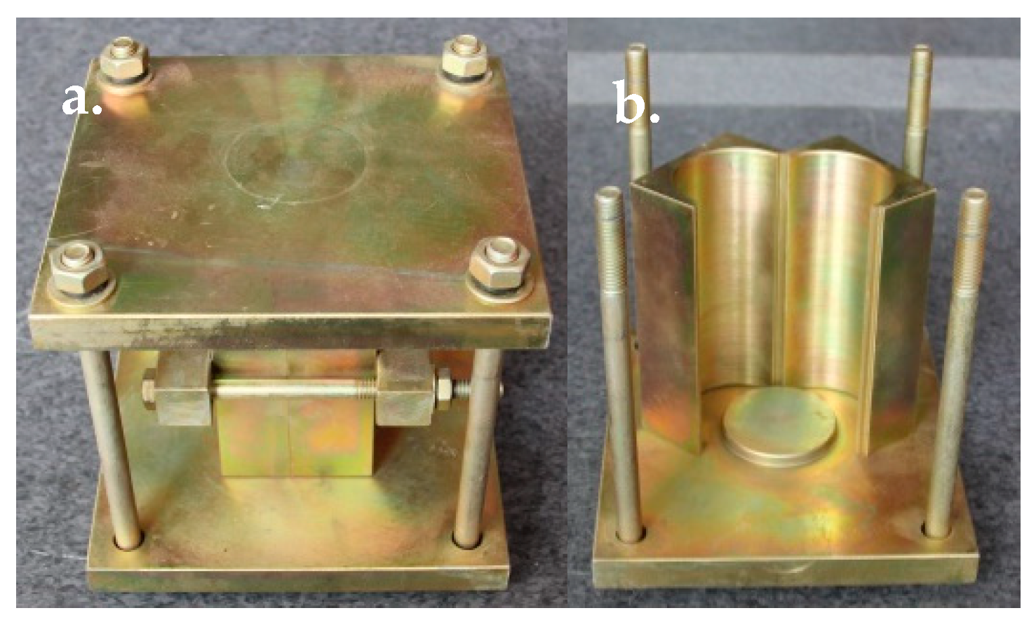
Taking into account the damage of the cemented specimen taken out from the mold, Yilmaz et al. recommend developing a method that could non-destructively produce the specimen [67]. Therefore, we designed a device for creating a cemented rockfill specimen [32], which included two halves of a cylinder, the upper and lower bases, bolts, and lateral fixing component, as shown in Figure 1. According to the standards of the American Society for Testing and Materials (ASTM) and the International Society for Rock Mechanics and Rock Engineering (ISRM), we used this device to produce the cemented rockfill specimen, which was a cylindrical specimen of ϕ50 × 100 mm [68,69,70]. The lateral fixing component was used to clamp the two halves of the cylinder in the production of the cemented rockfill specimen, as shown in Figure 1a. When the specimen needed to be removed from the mold, the clamped cylinder was split into two halves, as shown in Figure 1b.
The maximum particle size of the aggregate used in this test was 10 mm, as recommended by the ASTM and some other studies on the particle size effect [64,71]. The waste rock should be crushed and sieved into 0–0.5 mm, 0.5–1.0 mm, 1.0–1.5 mm, 1.5–2.5 mm, 2.5–5.0 mm, 5.0–8.0 mm, and 8.0–10.0 mm particles. The mass ratios of these seven particles can construct a seven-dimensional space of (Y1, Y2, Y3, Y4, Y5, Y6, Y7), which is difficult to quantify the effect of the particle size distribution on the mechanical parameters of cemented rockfill. Hence, the Talbot gradation was used to describe the particle size distribution of the aggregate in the cemented rockfill, which can overcome this curse of dimensionality [72]. At present, the Talbot gradation has been widely used in civil engineering [73]. It is a continuous exponential gradation, which is conducive for characterizing the particle distribution of the aggregate in cemented rockfill. Its function is:
where P is the mass ratio; dc is the current size of the particles; dmax is the maximum size of the particles; Mc is the mass of the particles below or equal to dc; Mt is the total mass of the particles; and, n is the Talbot index.
The mass of the particles in [d1, d2] can be calculated:
The total mass of particles in a specimen was 300 g, and Table 2 gives the mass distribution of the particles in the cemented rockfill specimens with Talbot indices of 0.2, 0.4, 0.6, and 0.8.
According to the experimental program in Table 3, a high-frequency vibration table and a mixer were first used to mix the cement and water for 10 min [74], which formed a uniform slurry that was then mixed with the prepared particles for 10 min [75], then poured into the device to produce a cemented rockfill specimen. The entire device must be fixed and then placed on a vibratory table for 5 min to optimize the specimen’s homogeneity [76]. The curing conditions of the cemented rockfill specimen were maintained at a humidity of 95% and temperature of 25 °C for seven days [77]. It should be noted that since the filling material has been subjected to the action from the coal seam roof at an early age, even under the condition of using some six-pillar hydraulic supports, the specimen with an early curing time of seven days was selected for testing to obtain the model parameters of the filling material established in the numerical model of a coal mine [78]. After curing, the specimen was removed from the curing box to check its non-parallelism and non-perpendicularity within ±0.02 mm, although it was produced in the device with rigid boundaries.
2.3. Experimental Equipment and Testing Process
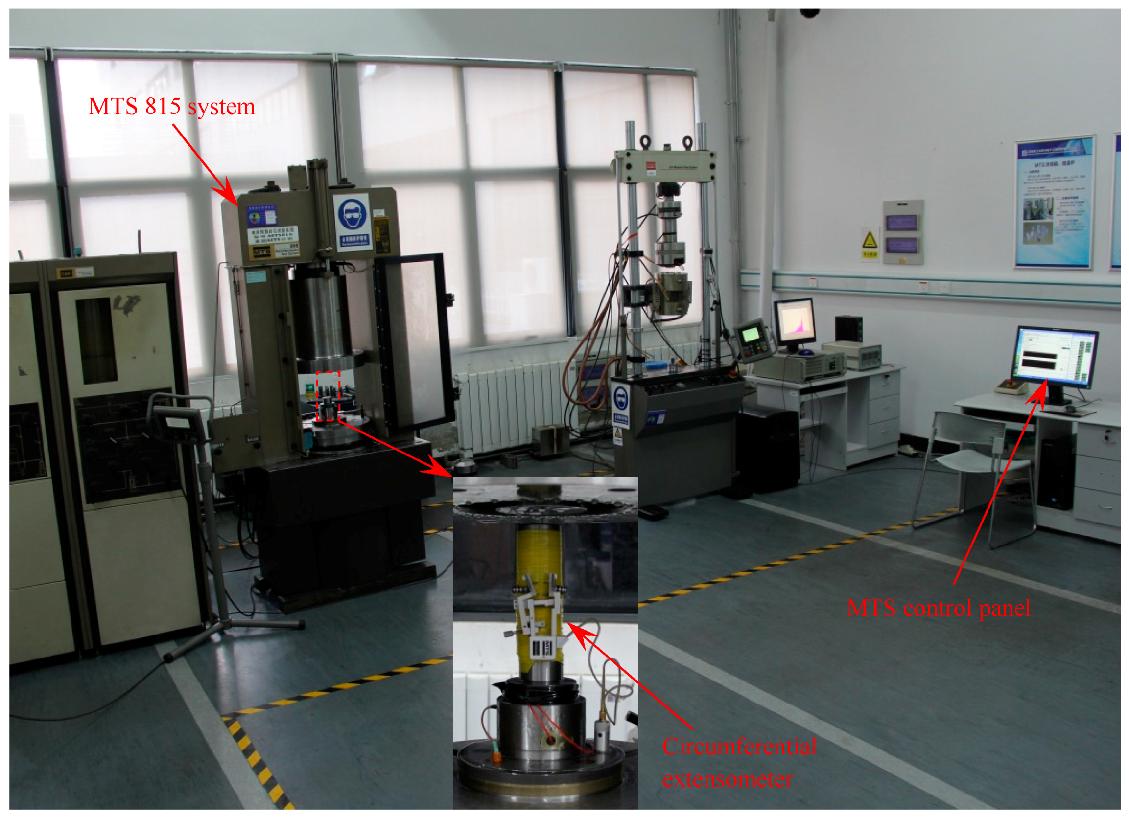
The MTS815 rock mechanics test system was used to carry out the uniaxial and triaxial compression tests, as shown in Figure 2. The initial pre-stress on the cemented rockfill specimen was 0.25 KN and the axial loading rate was 0.002 mm/s in both the uniaxial compression and triaxial compression tests [79]. It should be noted that the confining pressure must be loaded to the specific values of 0.5, 1, and 2 MPa at a rate of 0.04 MPa/s in the triaxial compression [80].
2.4. Particle Size Distribution of Aggregate Effects on the Mechanical Parameters of Cemented Rockfill
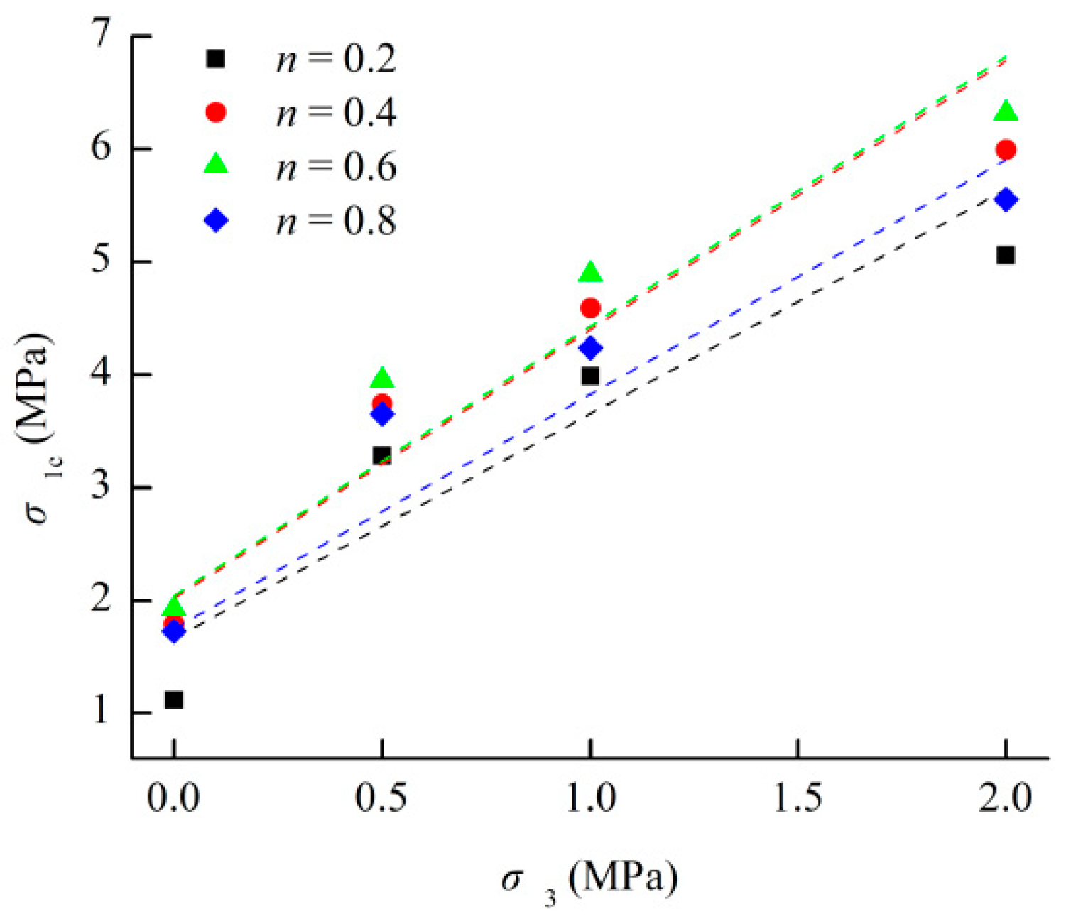
Figure 3 shows the relationship between the compressive strength of the cemented rockfill specimen and confining pressure under different granule gradations; the corresponding relationship is listed in Table 4. Then, the strength parameters of cohesive force, internal friction angle, and tensile strength can be obtained, being based on the Mohr-Coulomb strength criterion [81]:
where is the peak compressive strength; M and N are the strength parameters of the Mohr-Coulomb strength criterion; is the cohesive force; is the internal friction angle; and, is the peak tensile strength.
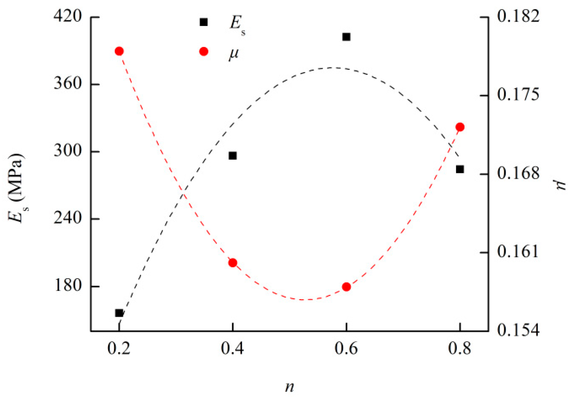
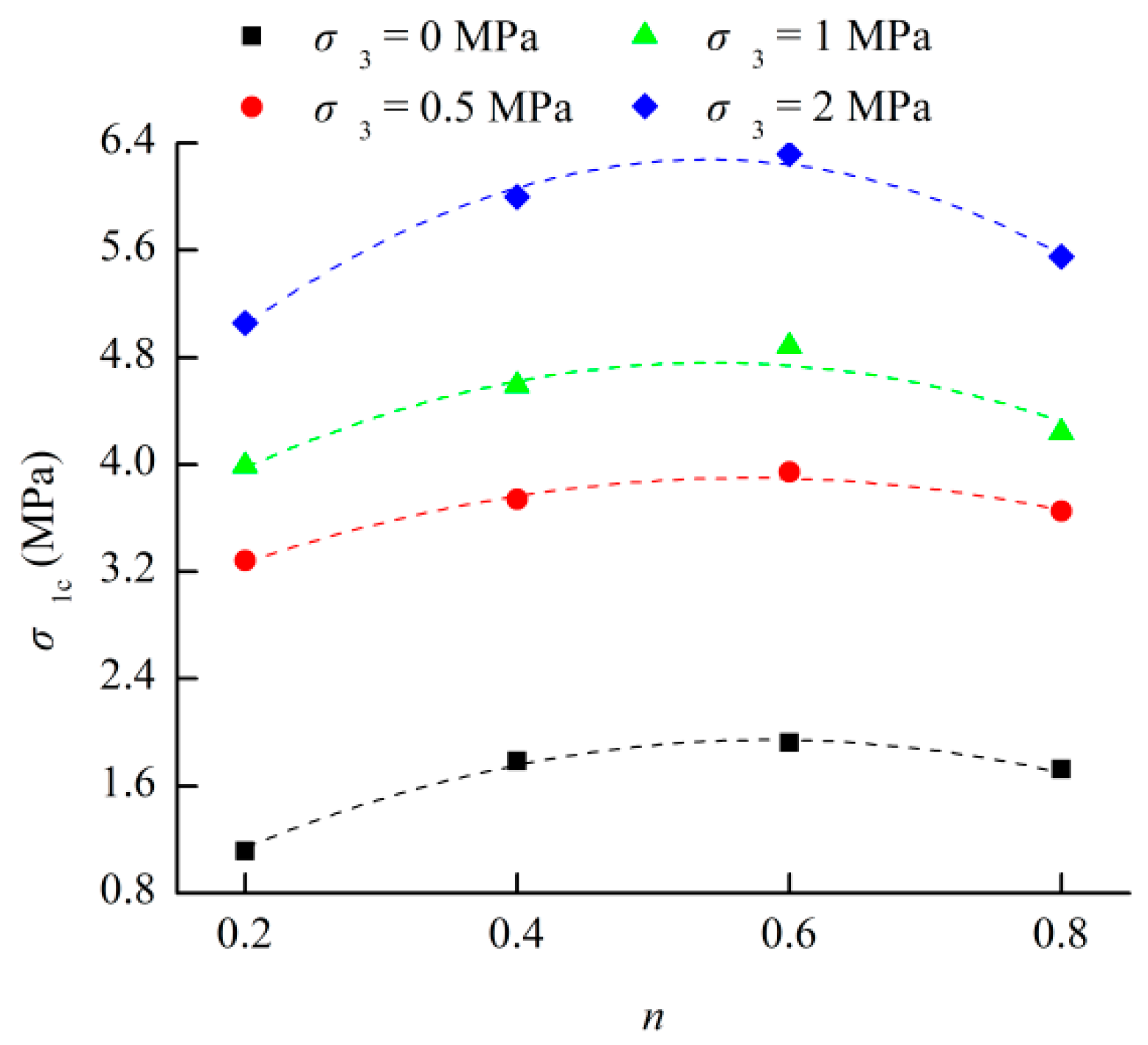
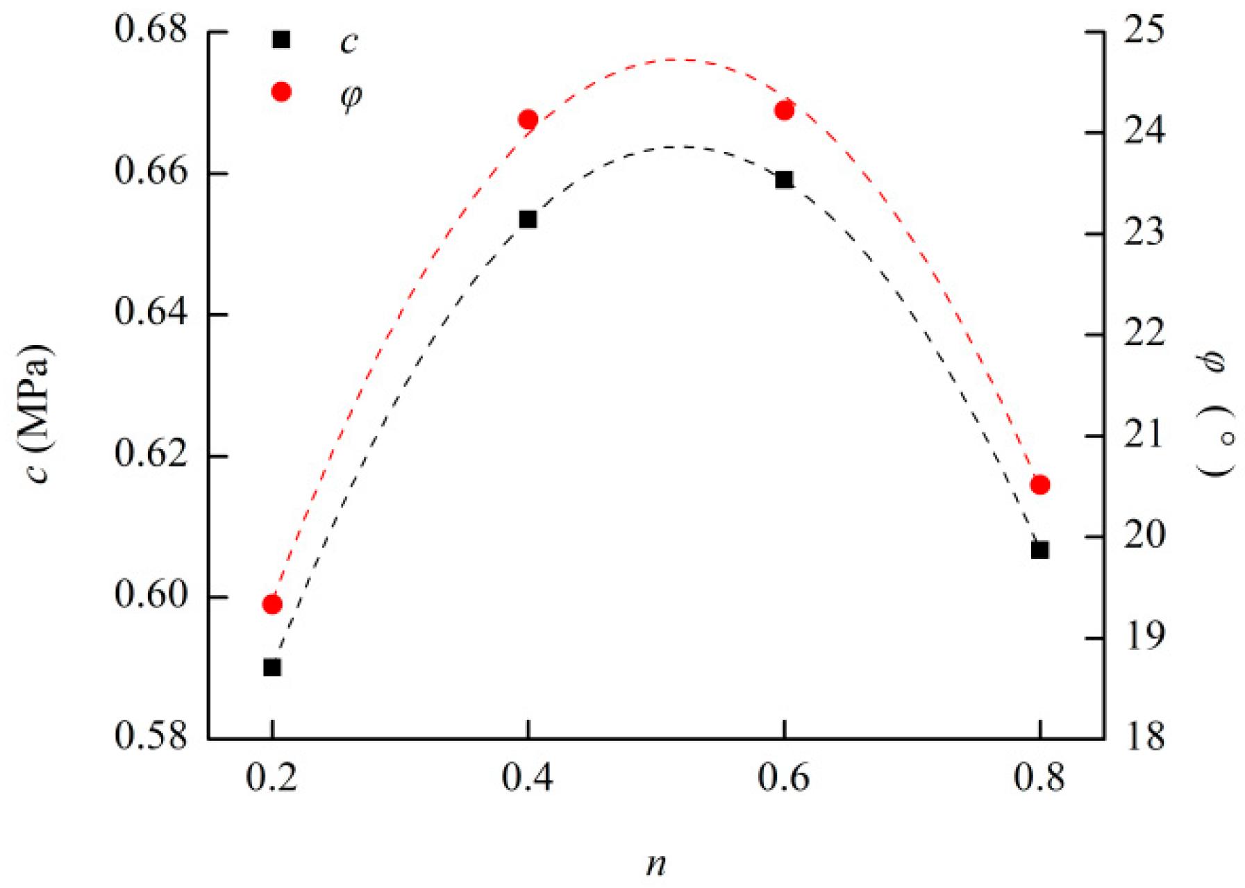
Figure 4, Figure 5, Figure 6 and Figure 7 give the relationships between the mechanical parameters (Poisson ratio, elastic modulus, compressive strength, cohesive force, internal friction angle, and tensile strength) of the cemented rockfill and the Talbot index of granule gradation and the corresponding relationships are presented in Table 5. It can be seen from the Figure 4, Figure 5, Figure 6 and Figure 7 that the Poisson ratio first decreased, and then increased with the increase of the Talbot index, however, other mechanical parameters first increased and then decreased with the increase of the Talbot index. This indicates that there is an optimal particle size distribution that can maximize the mechanical parameters of cemented rockfill, for which the optimal granule gradation is in the range of 0.4–0.6 based on the Talbot gradation. Therefore, the relations between the mechanical parameters of cemented rockfill and the Talbot index of granule gradation can be described by quadratic polynomial functions, and the extreme of the established function can be used to characterize the optimal granule gradation of the cemented filling material.
3. Numerical Simulation and Results
3.1. Establishment of Filling Mining Model in Coal Mine
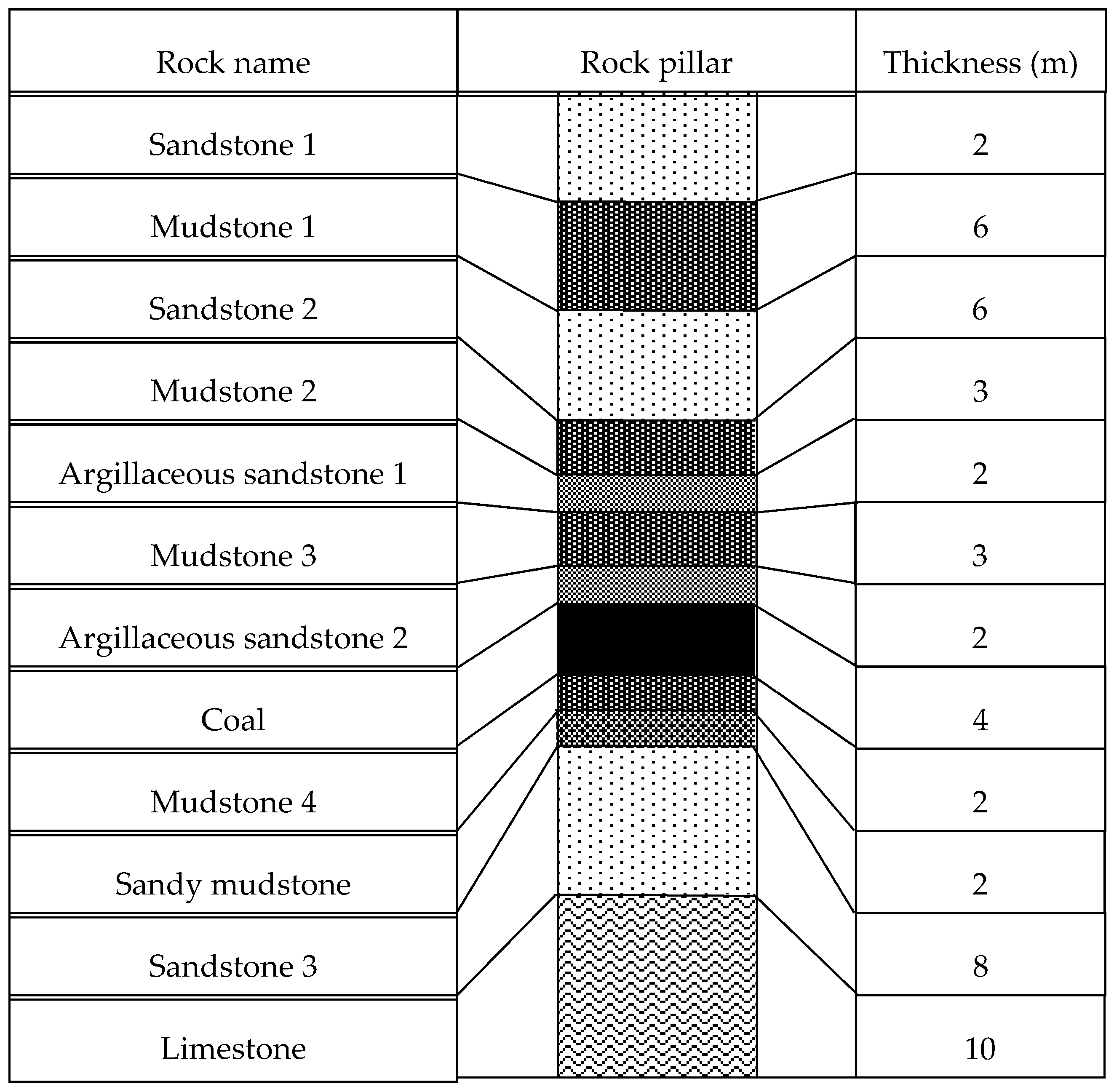
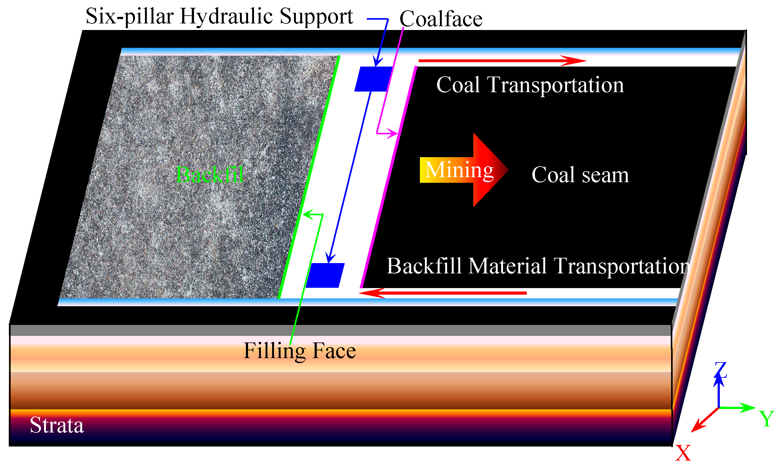
In a coal mine located in Anhui, China, the reserves of coal buried under railways, aquifers, and buildings reach 2.080 × 10⁷ t, the average thickness of the coal seam is 4 m at a buried depth of 525 m. Figure 8 presents the distribution and average thicknesses of each stratum above and below the coal seam in one coalface. The ground affecting area corresponding to the coal mining area contains the railways, highways, affiliated buildings, and some factories. In order to minimize the damage to the overlying strata and protect the surface structure [82], this coal mine applied the fully-mechanized longwall mining and filling [83]. Figure 9 shows the schematic diagram of the coalface in filling mining, where the span of this coalface was 100 m, and a shearer was used to mine the coal seam, and advanced in the Y direction [84]. One of the roadways at both ends of the coalface was used to transport the coal out from underground, apply the belt transportation, and the other roadway was used to transport the filling material from the ground to the filling area. The six-pillar hydraulic support was placed behind the coalface to support the coal seam roof, which could facilitate filling in the goaf. A plant for storing the cement material, a plant for storing the fly ash, and a plant for storing water were built on the ground and then connected to a mixing tank. The waste rock formed after ore treatment and gangue with low coal were stacked in a fixed area to produce the filling material. It should be noted that in this coal mine, the waste rock accounted for a lower proportion of the mined ore, so the solid waste that was produced by the surface factories in the mine area was applied, and an additional open quarry was built nearby to supplement a small amount of filling material. The crusher was arranged near the gangue mountain to facilitate the crushing of the waste rock and produce particles into the designed size. The crushed waste rock, cement material, fly ash, and water were mechanically transferred to the mixing tank according to the designed scheme to form a high-concentration slurry, which was transported underground through the pipeline under the condition of using the filling material’s own gravity and the filling pump to fill the goaf [85].
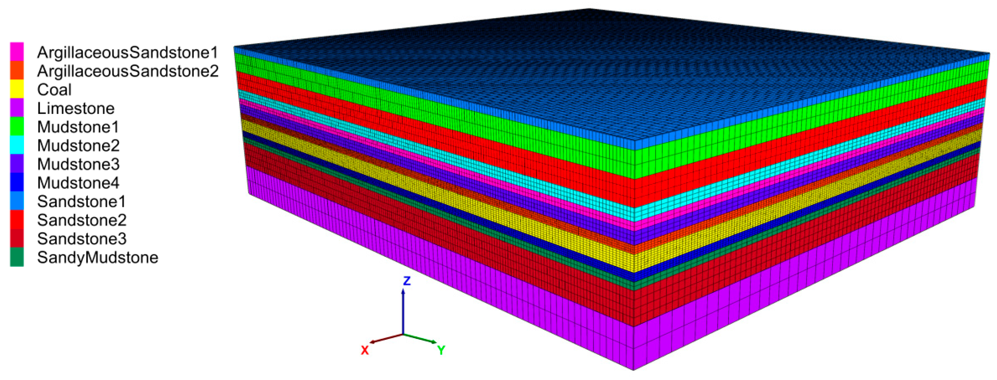
Based on the above engineering background, a numerical model of a coalface in the coal mine was established to simulate the processes of excavation and filling in FLAC3D, where the model size of (X, Y, Z) was (160 m, 180 m, 50 m). The coalface was along the X direction with a span of 100 m, leaving 30 m left and right. The mining direction was along the Y direction with a total mining distance of 120 m, leaving 30 m at the front and rear. The meshes of coal seam and its roof and floor strata were refined, the Coal, Argillaceous sandstone 2, and Mudstone 4 were divided into one unit every 1 × 0.5 × 0.5 m3, and the entire model was divided into 986,400 units and 1,085,879 nodes, as shown in Figure 10. A uniform load of 12.5 MPa was applied to the top surface of the model to simulate a buried depth of 525 m, and a horizontal constraint was imposed on the surrounding boundaries and a vertical constraint imposed on the bottom boundary. The contact difficulty between the cemented filling material and the coal seam roof was not considered in the establishment of this model; it was assumed that the filling material could completely fill the goaf. The initial coalface was located at X from 30 m to 130 m, Y of 30 m, Z from 22 m to 26 m, and advanced in the Y direction. According to the actual working condition, in the first step, the coal seam was excavated from m to m, and the goaf in was immediately filled with the cemented rockfill, then the model was balanced. In the second step, the coal seam was excavated from m to m, and the goaf in was immediately filled with the cemented rockfill, then the model was also balanced. When it was mined to 120 m in this way, the model was balanced and stopped. Here, according to the advancement distance of the coalface in the actual effective mining stage in the engineering, the mining distance of each step was designed as 20 m. The Mohr-Coulomb model was used for both the rock mass and the backfill, and the specific model parameters are shown in Table 6 and Table 7.
3.2. Particle Size Distribution of Aggregate in Cemented Rockfill Effects on Displacement Field of Strata
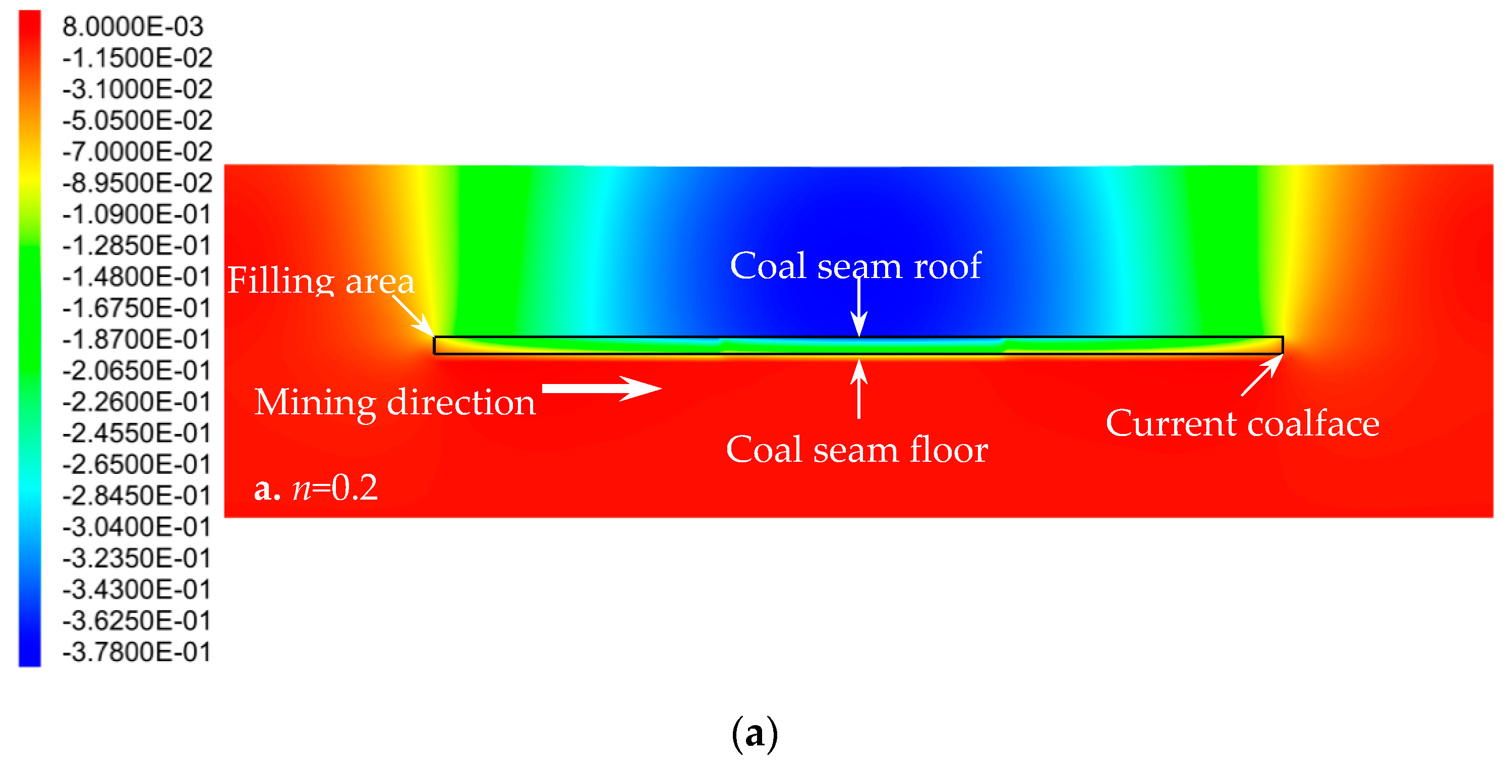
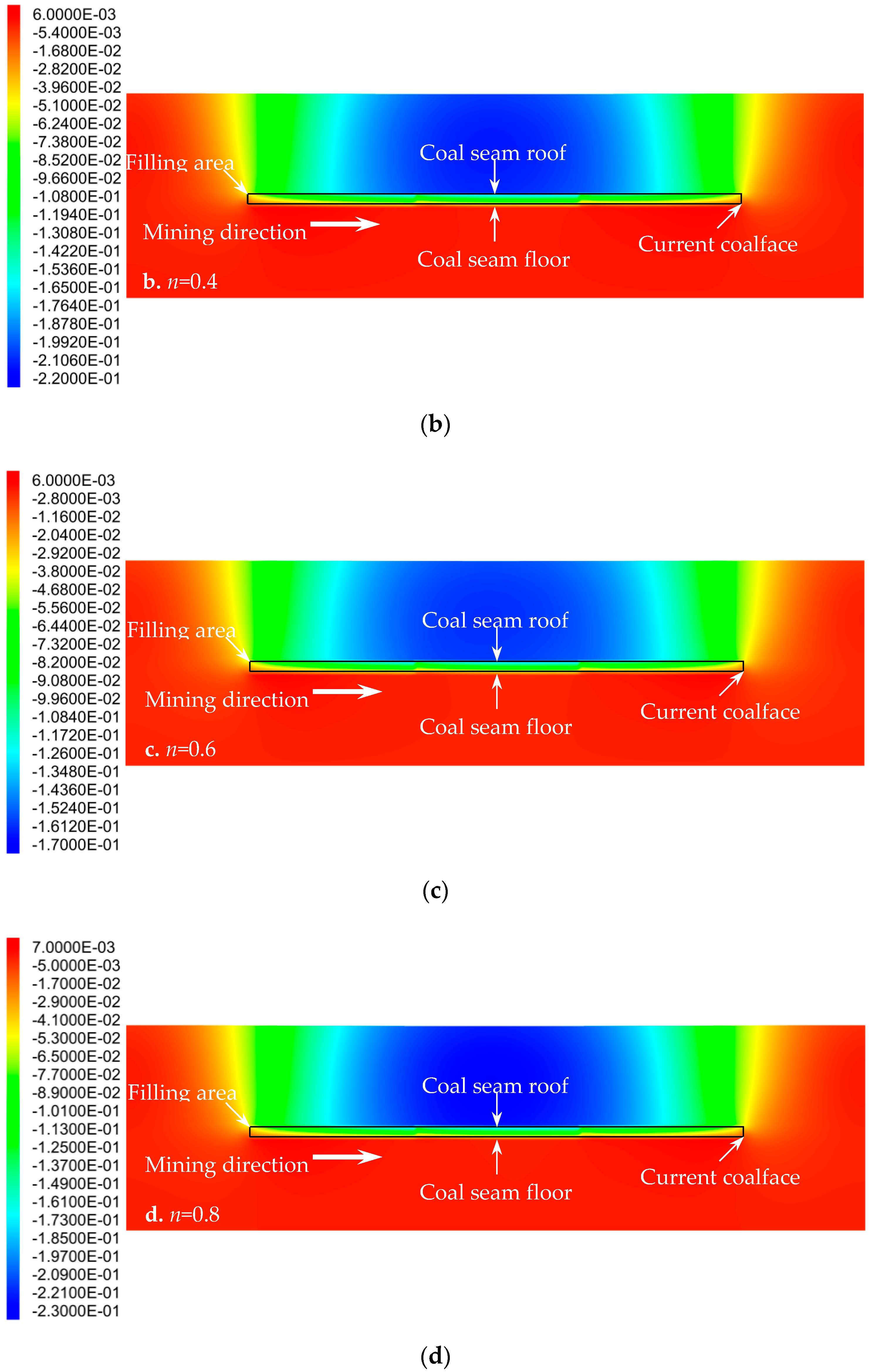
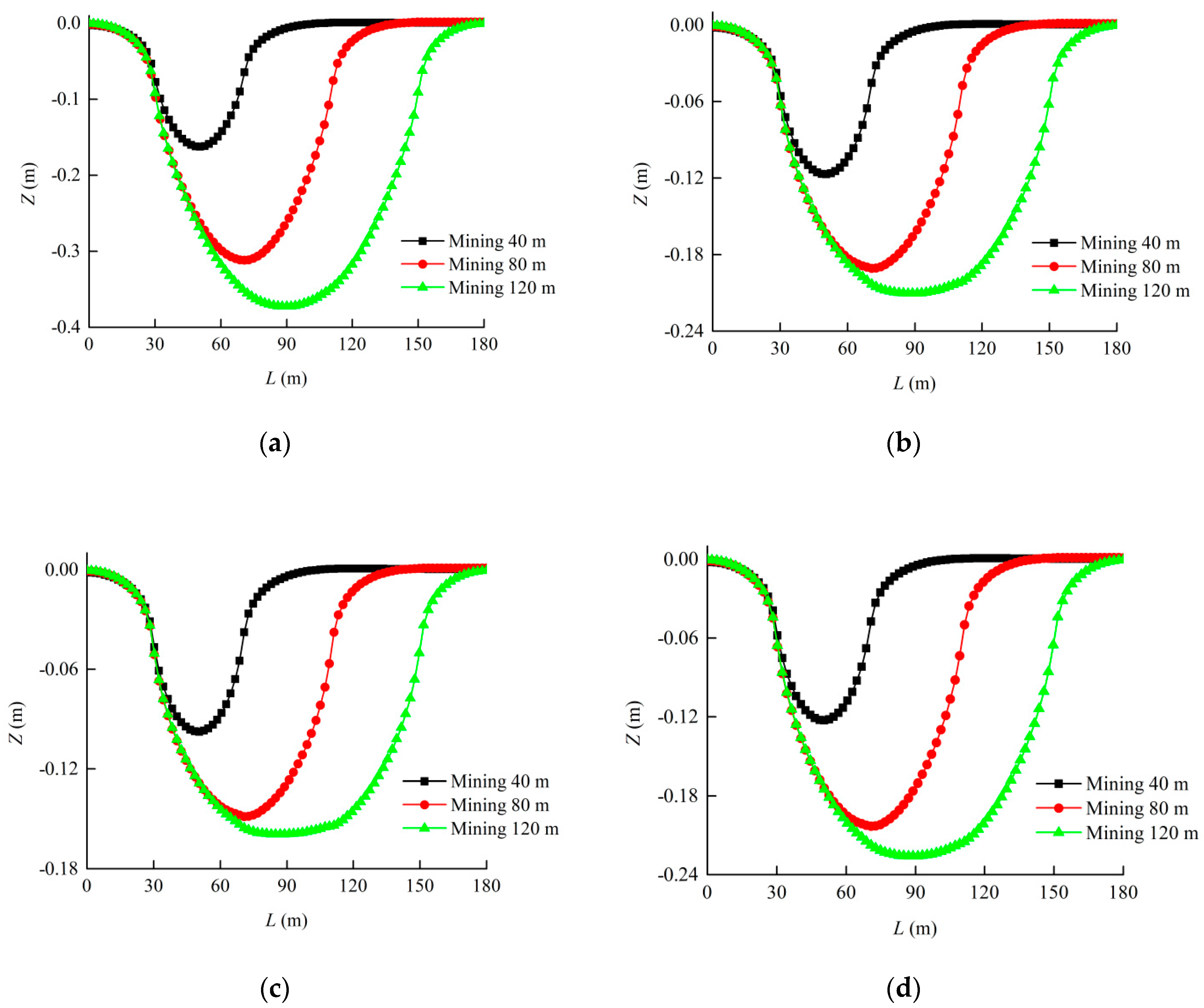
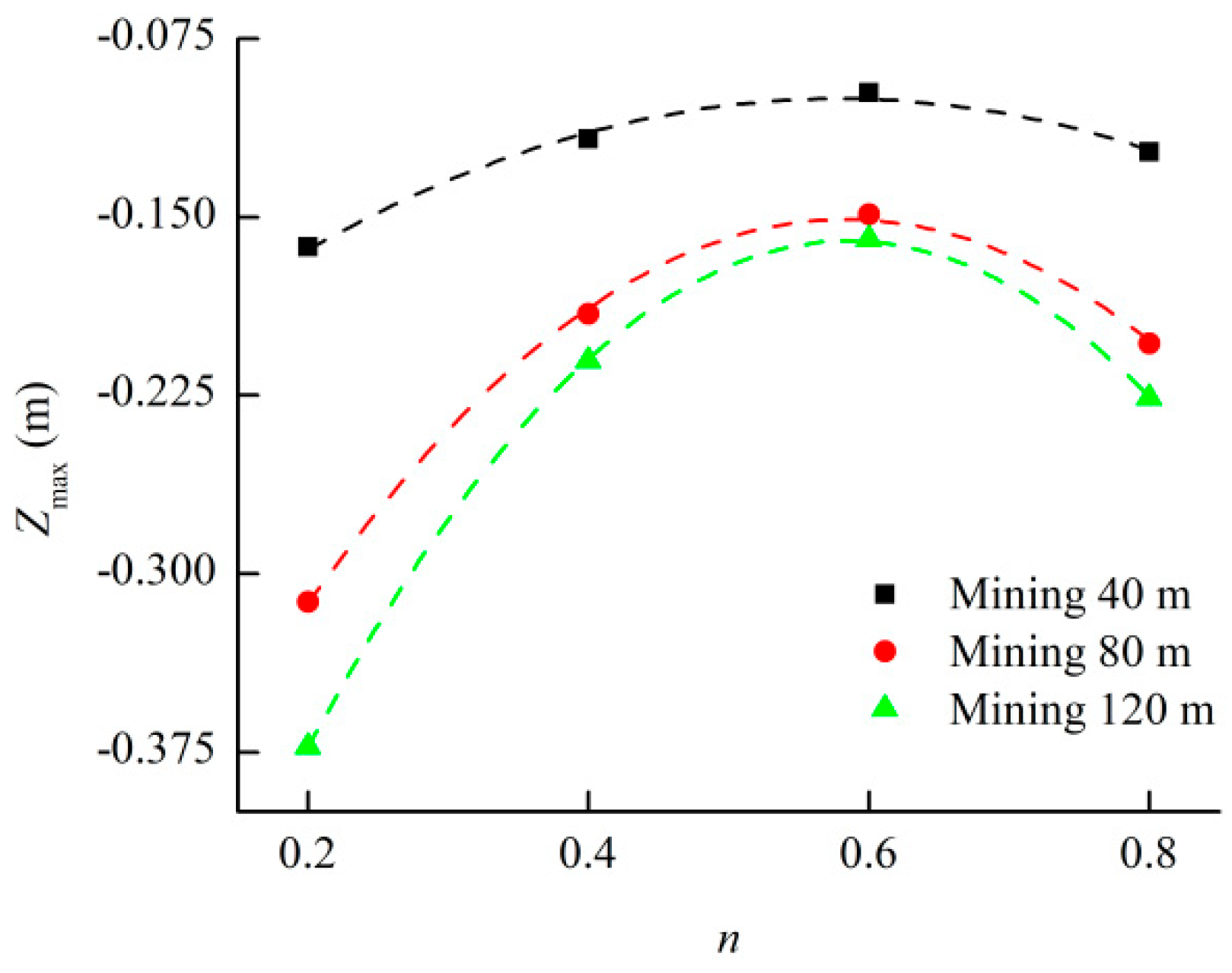
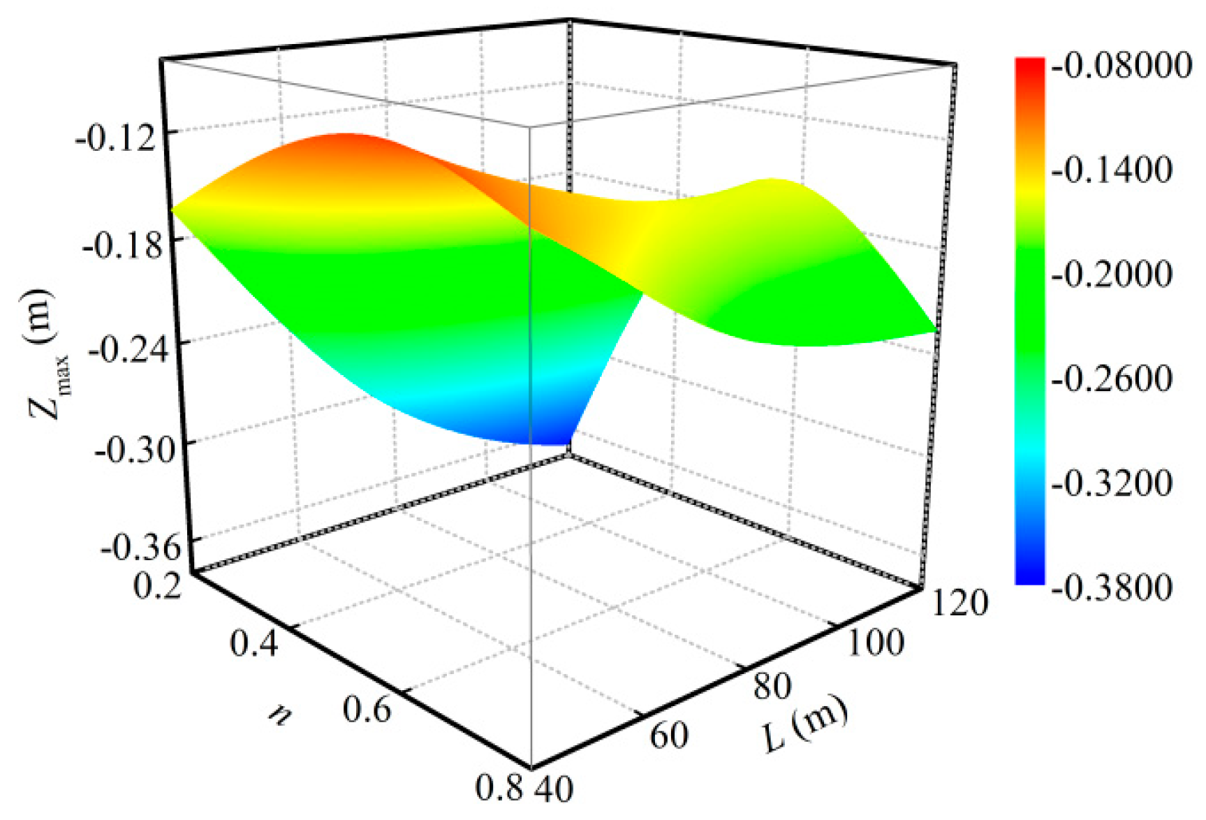
Figure 11 gives the Z-direction displacement field of the strata (Y–Z profile at X of 80 m), when the goaf was filled with cemented rockfill with different granule gradations at a mining distance of 120 m. It can be seen from the Figure 11 that the movement of each stratum was mainly located above the filling area. The closer to the filling area, the greater the subsidence displacement of the stratum, and is concentrated in the middle of each stratum. As both ends of the filling area can still rely on the original rock mass to load, it presents a small subsidence displacement. The cemented rockfill with different granule gradations has a great effect on the movement of each stratum in filling mining, where the subsidence displacement of the overlying strata is the largest when the goaf is filled with cemented rockfill with a Talbot index of 0.2, while that of the other Talbot indices of granule gradations are relatively small. In order to quantify the influence of the particle size distribution of the aggregate in the cemented rockfill on the subsidence displacement of the overlying strata, Figure 12 presents the subsidence displacement of the coal seam roof at different mining distances when the goaf was filled with cemented rockfill with different granule gradations. Figure 13 shows the relationship between the maximum subsidence displacement of the coal seam roof and the Talbot index of cemented rockfill at different mining distances, and Figure 14 presents the coupling effect of the cemented rockfill’s granule gradation and mining distance on the maximum subsidence displacement of the coal seam roof. It can be seen from the Figure 12, Figure 13 and Figure 14 that the subsidence displacement of the coal seam roof increased with the advancement of the coalface, but the fall velocity gradually slowed down. The maximum subsidence displacement always occurred above the middle of the filling area, and it had a quadratic polynomial relation with the Talbot index of the cemented rockfill; the corresponding relationship is listed in Table 8. When filling mining at 40 m with the cemented rockfill applied with different granule gradations, the difference among the maximum subsidence displacements of the coal seam roof was not large, and the displacements were maintained at about 0.10–0.15 m. However, with the advancement of the coalface, the cemented rockfill with different granule gradations had a great effect on the maximum subsidence displacements of the coal seam roof. When filling mining at 120 m, the maximum subsidence displacement when using the cemented rockfill with a Talbot index of 0.6 was only 0.1593 m, which was not too different from that of 0.1172 m when filling mining at 40 m. It was considered that the subsidence displacement gradually becomes stable with the advancement of the coalface, and the cemented rockfill with a Talbot index of 0.6 was superior and it could effectively control the movement of the overlying strata. Conversely, when the goaf was filled with cemented rockfill with a Talbot index of 0.2 at the mining distance of 120 m, the maximum subsidence displacement of the coal seam roof reached 0.3728 m, and there was still a tendency to continue to fall. The filling effect while using this cemented rockfill with a Talbot index of 0.2 was obviously poor, which was also fully reflected in the spatial relation of Figure 13. Thus, it was considered that optimizing the particle size distribution of the aggregate in the cemented rockfill could effectively control the strata movement.
3.3. Particle Size Distribution of Aggregate in Cemented Rockfill Effects on Stress Field of Strata
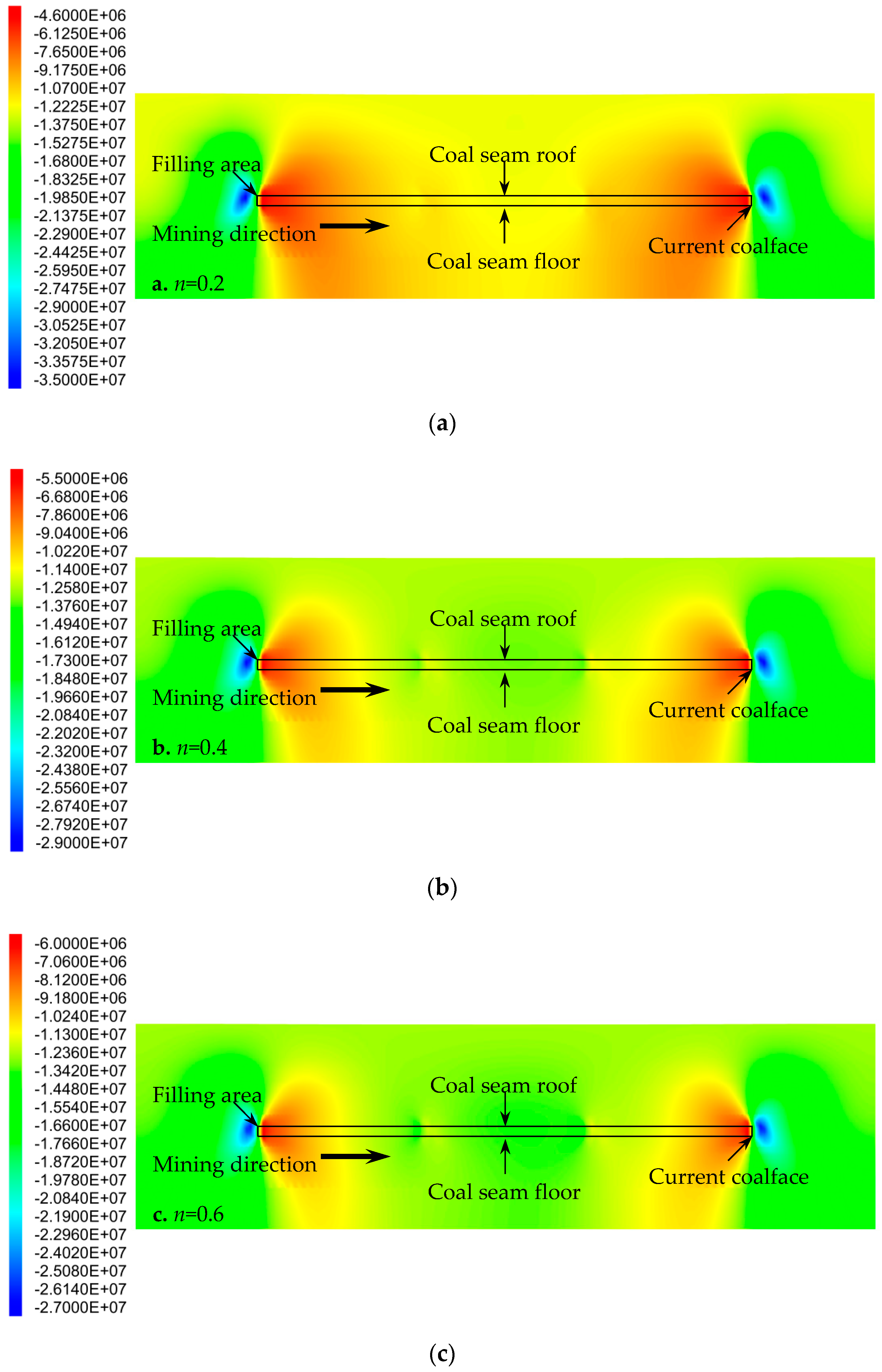
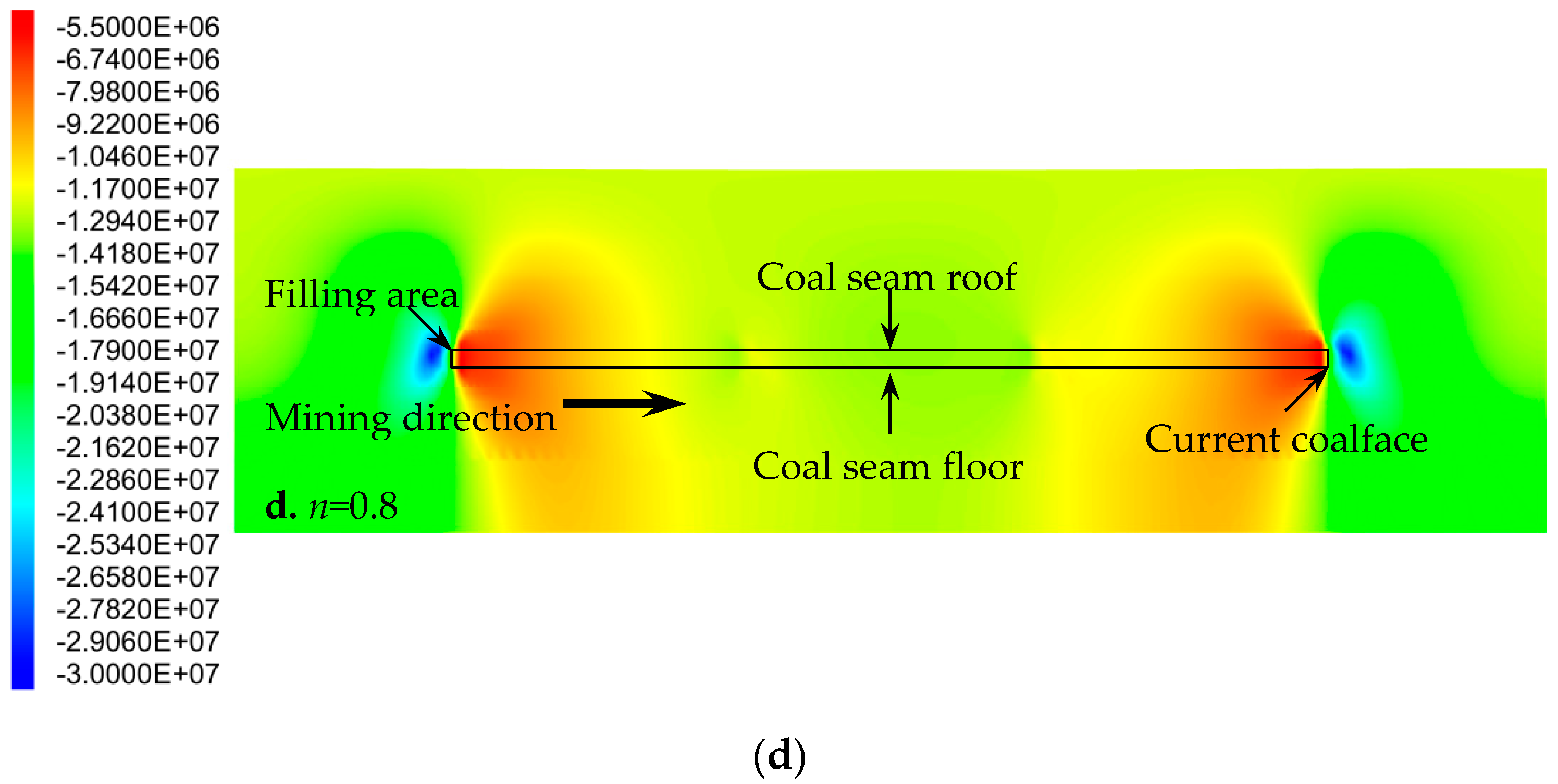
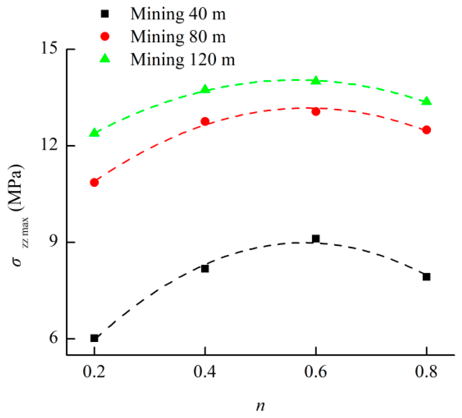
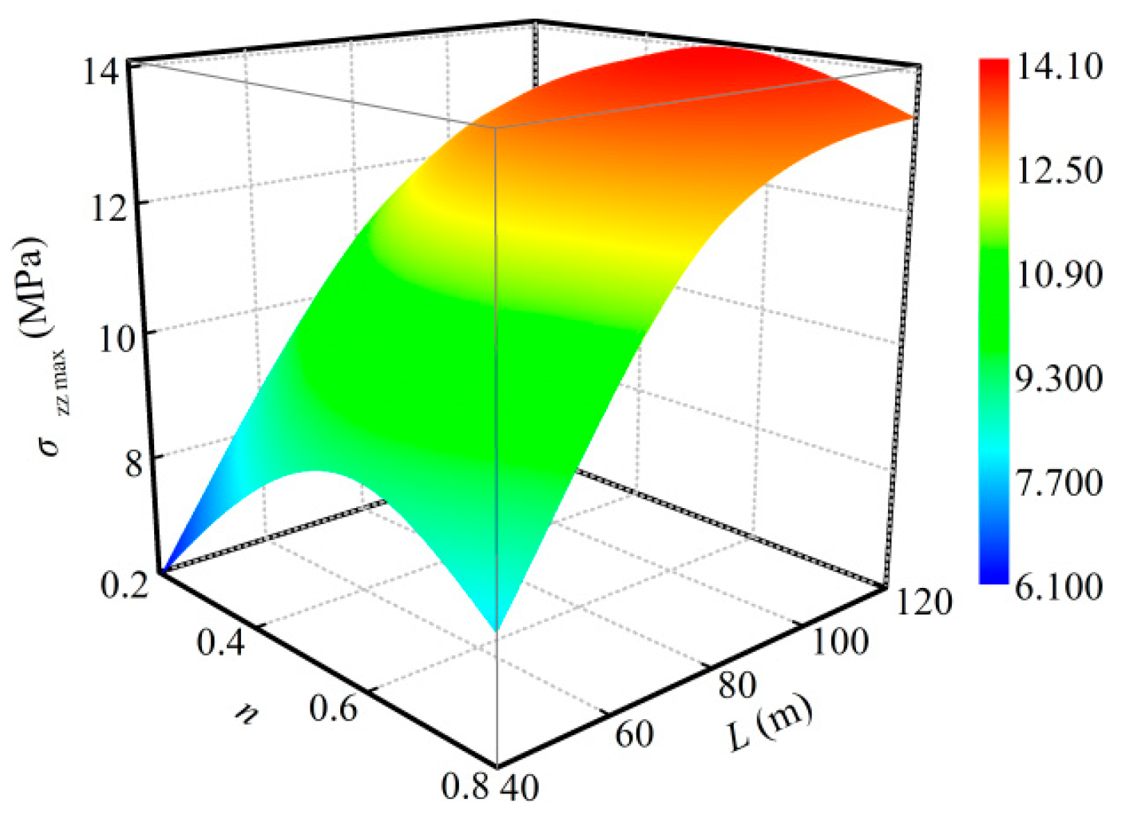
Figure 15 gives the Z-direction stress field of the strata (Y-Z profile at X of 80 m) when the goaf was filled with cemented rockfill with different granule gradations at a mining distance of 120 m. It was not difficult to see from the Figure 15 that the stress was concentrated in the rock mass in the coalface. The stress field distribution in the filling area presented large stress in the middle part and small stress in the two ends. This distribution characteristic is also suitable for describing that of each stratum above and below the filling area. The excavation and unloading of the coal mass caused the rock mass at both ends of the filling area to load most of the stress. Then, while using the cemented rockfill material to fill the part of the excavation, the subsidence deformations of the coal seam roof and its overlying strata were diffused from the middle to both ends, and the displacement and stress in the middle of the backfill gradually decreased towards both ends. The cemented rockfill with different granule gradations had a great effect on the stress fields of the rock mass and backfill. The stress of the rock mass in the coalface was the highest when the goaf was filled with the cemented rockfill with a Talbot index of 0.2, while the internal stress of the backfill was the smallest. This was the opposite of the cemented rockfill with other granule gradations. In order to quantify the influence of the particle size distribution of the aggregate in the cemented rockfill on the stress field of the strata, Figure 16 provides the internal stress of the backfill at different mining distances when the goaf was filled by cemented rockfill with different granule gradations; Figure 17 presents the relationship between the maximum internal stress of the backfill and the Talbot index of the cemented rockfill at different mining distances; Figure 18 plots the coupling effect of the cemented rockfill’s granule gradation and the mining distance on the maximum internal stress of backfill; Figure 19 shows the relationship between the maximum stress of the rock mass in the coalface and the Talbot index of the cemented rockfill at different mining distances; and, Figure 20 depicts the coupling effect of the cemented rockfill’s granule gradation and the mining distance on the maximum stress of the rock mass in the coalface. It is easy to see from the Figure 16, Figure 17, Figure 18, Figure 19 and Figure 20 that the internal stress of the backfill and the stress of the rock mass in the coalface increased with the advancement of the coalface, but the increasing rates gradually slowed down. The maximum internal stress of the backfill was always located in the middle of the filling area, where the maximum value was in a quadratic polynomial relation with the Talbot index of the cemented rockfill, the corresponding relationship is listed in Table 9. This function is also suitable for describing the relationship between the stress of the rock mass in the coalface and the Talbot index of the cemented rockfill, as shown in Table 10. When the goaf was filled by the cemented rockfill with different granule gradations, the internal stress of the backfill and the stress of the rock mass in the coalface presented huge differences, where the differences among the internal stresses of backfills could reach 3 MPa, and the difference among the stresses of the rock mass in the coalface could reach 9 MPa. Here, the filling effect of the cemented rockfill with a Talbot index of 0.6 was obviously better than those with other granule gradations. It was considered that optimizing the particle size distribution of the aggregate in the cemented rockfill could improve the loading capacity of the backfill to improve the filling effect, and it could decrease the internal stress of the rock mass in the coalface to reduce the potential dangers around the coalface, such as rock burst.
4. Discussions
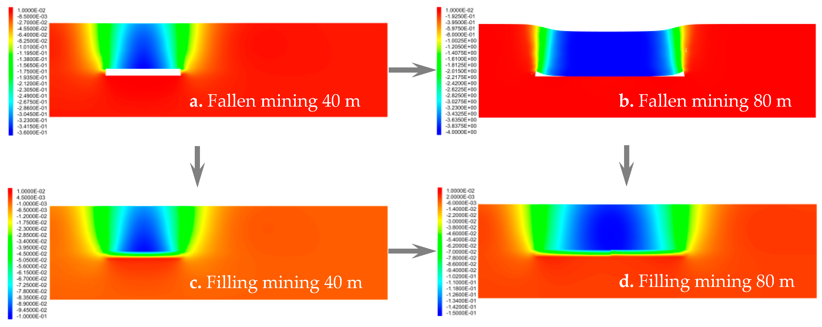
Figure 20 gives the Z-direction displacement field of the strata (Y-Z profile at X of 80 m) at mining distances of 40 m to 80 m under fallen mining and filling mining with n = 0.6 cemented rockfill. It can be seen from the Figure 20 that the displacement fields under both of the mining methods were not too different when the excavation was small, that is, 40 m, as shown in Figure 21a,c. The subsidence displacements of the coal seam roof were maintained at the same magnitude, so the hard roof will not fracture, causing a larger subsidence displacement under this condition. However, with the advancement of the coalface, the overlying strata upper coal seam were continuously bent and deformed under the tensile shear stress. A large number of fissures were generated inside the rock mass, and the transfixions of the fissures caused fractures in the coal seam roof and the overlying key rock formation, so the overlying strata completely collapsed, as represented in Figure 21b. However, the maximum subsidence displacement while using filling mining with n = 0.6 cemented rockfill was only 0.15 m, which protected the integrity of the overlying strata. Therefore, it is beneficial to control the strata movement and protect the structure of the underground key rock formation. This paper mainly discussed the influence of the particle size distribution of the aggregate in the cemented rockfill on the stability of the strata in the filling mining instant. The influence of the difference between the cemented filling materials on the displacement and stress fields of the strata was analyzed based on the actual cemented rockfill in the test. The results showed that optimizing the particle size distribution of the aggregate in cemented rockfill could increase the loading capacity of the backfill to improve the filling effect, effectively control the strata movement, and decrease the stress of the rock mass in the coalface to reduce the potential danger. It can be promoted in engineering to benefit the economics, safety, and stability. However, the backfill is in a creep state under three-direction compression during its service. Although it shows a perfect engineering behavior in the mining instant, it is not enough to prove that it can perfectly protect the overlying strata above the coal seam during the whole service process. For this purpose, it is necessary to study the mechanical behavior of the cemented rockfill with different particle size distributions under creep in order to reproduce the displacement and stress fields of the strata in filling mining with the cemented rockfill during the creep process, and to investigate whether the optimization on the particle size distribution of the aggregate in the cemented rockfill under the creep condition can still protect the stability of the underground structure and the integrity of the overlying strata, which will be the subject of the authors’ future work.
5. Conclusions
This paper was based on a specific coal mine where we applied the fully-mechanized longwall mining and filling and designed a cemented rockfill material, for which the particles satisfied the Talbot gradation. The uniaxial and triaxial compression experiments were carried out on the cemented rockfill specimen, which obtained the relationships between the mechanical parameters (Poisson ratio, elastic modulus, compressive strength, cohesive force, internal friction angle, and tensile strength) and the particle size distribution of the aggregate. The excavation and filling processes in the coal seam were simulated based on the numerical software FLAC3D. The characteristics of the displacement and stress fields of the strata were discussed when the goaf was filled with cemented rockfill with different granule gradations. The influences of the particle size distribution and mining distance on the maximum subsidence displacement of the coal seam roof, internal stress of the backfill, and the stress of the rock mass in the coalface were analyzed. The feasibility and effectiveness of the filling mining with the cemented rockfill to protect the integrity of the overlying strata were discussed.
- (1)
- The relationships between the mechanical parameters (Poisson ratio, elastic modulus, compressive strength, cohesive force, internal friction angle, and tensile strength) of the cemented rockfill and the Talbot index of granule gradation can be described by quadratic polynomial functions, and the extreme of the established function can be used to characterize the optimal granule gradation of the cemented rockfill material.
- (2)
- The movement of each stratum was mainly located above the filling area. The closer to the filling area, the greater the subsidence displacement of the stratum; the subsidence displacement was concentrated in the middle of each stratum. As both ends of the filling area could still rely on the original rock mass to load, it presented a small subsidence displacement. The subsidence displacements of the overlying strata increased with the advancement of the coalface, but the fall velocity gradually slowed down. The maximum subsidence displacement always occurred above the middle of the filling area, and it had a quadratic polynomial relation with the Talbot index of the cemented rockfill. It was considered that optimizing the particle size distribution of the aggregate in the cemented rockfill could effectively control the strata movement.
- (3)
- The stress of the strata was concentrated in the rock mass in the coalface. The stress field distribution in the filling area presented a large stress in the middle part and small stress at the two ends. This distribution characteristic was also suitable for describing that of each stratum above and below the filling area. The internal stress of the backfill and the stress of the rock mass in the coalface increased with the advancement of the coalface, but the increasing rates gradually slowed down. The maximum internal stress of the backfill was always located in the middle of the filling area, where the maximum value was in a quadratic polynomial relation with the Talbot index of the cemented rockfill. This function is also suitable for describing the relationship between the stress of the rock mass in the coalface and the Talbot index of the cemented rockfill. It was considered that optimizing the particle size distribution of the aggregate in the cemented rockfill could improve the loading capacity of the backfill in order to improve the filling effect, and it could decrease the internal stress of the rock mass in the coalface to reduce the potential dangers around the coalface.
Author Contributions
J.W. and M.F. conceived and designed the experiments; J.W., Y.W. and G.H. performed the experiments; J.W., J.X. and P.Q. completed the numerical simulations; J.W. and M.F. analyzed the data; and J.W. and M.F. wrote the paper.
Funding
This work was supported by the Fundamental Research Funds for the Central Universities (No. 2018BSCXB22) and the Postgraduate Research & Practice Innovation Program of Jiangsu Province (KYCX18_1970).
Acknowledgments
The authors would like to thank Xianbiao Mao, Yushou Li and Zhanqing Chen for the experimental materials and equipment support.
Conflicts of Interest
The authors declare no conflict of interest.
References
- Deng, D.Q.; Liu, L.; Yao, Z.L.; Song, K.; Lao, D.Z. A practice of ultra-fine tailings disposal as filling material in a gold mine. J. Environ. Manag. 2017, 196, 100–109. [Google Scholar] [CrossRef] [PubMed]
- Li, X.B.; Li, D.Y.; Liu, Z.X.; Zhao, G.Y.; Wang, W.H. Determination of the minimum thickness of crown pillar for safe exploitation of a subsea gold mine based on numerical modelling. Int. J. Rock Mech. Min. Sci. 2013, 57, 42–56. [Google Scholar] [CrossRef]
- Liu, R.; Li, B.; Jiang, Y. Critical hydraulic gradient for nonlinear flow through rock fracture networks: The roles of aperture, surface roughness, and number of intersections. Adv. Water. Resour. 2016, 88, 53–65. [Google Scholar] [CrossRef]
- Liu, R.; Jiang, Y.; Li, B.; Yu, L. Estimating permeability of porous media based on modified Hagen–Poiseuille flow in tortuous capillaries with variable lengths. Microfluid. Nanofluid. 2016, 20, 120. [Google Scholar] [CrossRef]
- Liu, R.; Li, B.; Yu, L.; Jiang, Y.; Jing, H. A discrete-fracture-network fault model revealing permeability and aperture evolutions of a fault after earthquakes. Int. J. Rock. Mech. Min. 2018, 107, 19–24. [Google Scholar] [CrossRef]
- Zhang, J.X.; Li, B.Y.; Zhou, N.; Zhang, Q. Application of solid backfilling to reduce hard-roof caving and longwall coal face burst potential. Int. J. Rock Mech. Min. Sci. 2016, 88, 197–205. [Google Scholar] [CrossRef]
- Zhang, K.; Yang, T.H.; Bai, H.B.; Gamage, R.P. Longwall mining–induced damage and fractures: Field measurements and simulation using FDM and DEM coupled method. Int. J. Geomech. 2018, 18, 04017127. [Google Scholar] [CrossRef]
- Li, M.; Zhang, J.X.; Huang, Y.L.; Zhou, N. Effects of particle size of crushed gangue backfill materials on surface subsidence and its application under buildings. Environ. Earth Sci. 2017, 76, 603. [Google Scholar] [CrossRef]
- Zhang, J.X.; Li, M.; Liu, Z.; Zhou, N. Fractal characteristics of crushed particles of coal gangue under compaction. Powder Technol. 2017, 305, 12–18. [Google Scholar] [CrossRef]
- Li, M.; Zhang, J.X.; Quan, K.; Zhou, N. Innovative Extraction Method for a Coal Seam with a Thick Rock-Parting for Supporting Coal Mine Sustainability. Sustainability 2017, 9, 1982. [Google Scholar] [CrossRef]
- Sivakugan, N.; Rankine, R.M.; Rankine, K.J.; Rankine, K.S. Geotechnical considerations in mine backfilling in Australia. J. Clean. Prod. 2006, 14, 1168–1175. [Google Scholar] [CrossRef]
- Benzaazoua, M.; Belem, T.; Bussière, B. Chemical factors that influence the performance of mine sulphidic paste backfill. Cem. Concr. Res. 2002, 32, 1133–1144. [Google Scholar] [CrossRef]
- Belem, T.; Benzaazoua, M. Design and application of underground mine paste backfill technology. Geotech. Geol. Eng. 2008, 26, 147–174. [Google Scholar] [CrossRef]
- Abdul-Hussain, N.; Fall, M. Thermo-hydro-mechanical behaviour of sodium silicate-cemented paste tailings in column experiments. Tunn. Undergr. Space Technol. 2012, 29, 85–93. [Google Scholar] [CrossRef]
- Holt, E.; Leivo, M. Cracking risks associated with early age shrinkage. Cem. Concr. Compos. 2004, 26, 521–530. [Google Scholar] [CrossRef]
- Ouellet, S.; Bussière, B.; Aubertin, M.; Benzaazoua, M. Characterization of cemented paste backfill pore structure using SEM and IA analysis. Bull. Eng. Geol. Environ. 2008, 67, 139–152. [Google Scholar] [CrossRef]
- Wu, A.X.; Wang, Y.; Wang, H.J.; Yin, S.H.; Miao, X.X. Coupled effects of cement type and water quality on the properties of cemented paste backfill. Int. J. Min. Process. 2015, 143, 65–71. [Google Scholar] [CrossRef]
- Ouellet, S.; Bussière, B.; Mbonimpa, M.; Benzaazoua, M.; Aubertin, M. Reactivity and mineralogical evolution of an underground mine sulphidic cemented paste backfill. Miner. Eng. 2006, 19, 407–419. [Google Scholar] [CrossRef]
- Fall, M.; Benzaazoua, M.; Saa, E.G. Mix proportioning of underground cemented tailings backfill. Tunn. Undergr. Space Technol. 2008, 23, 80–90. [Google Scholar] [CrossRef]
- Liu, Z.X.; Dang, W.G.; Liu, Q.L.; Chen, G.H.; Peng, K. Optimization of clay material mixture ratio and filling process in gypsum mine goaf. Int. J. Min. Sci. Technol. 2013, 23, 337–342. [Google Scholar] [CrossRef]
- Fall, M.; Benzaazoua, M. Modeling the effect of sulphate on strength development of paste backfill and binder mixture optimization. Cem. Concr. Res. 2005, 35, 301–314. [Google Scholar] [CrossRef]
- Yin, S.H.; Wu, A.X.; Hu, K.J.; Wang, Y.; Zhang, Y.K. The effect of solid components on the rheological and mechanical properties of cemented paste backfill. Miner. Eng. 2012, 35, 61–66. [Google Scholar] [CrossRef]
- Ke, X.; Hou, H.; Zhou, M.; Wang, Y.; Zhou, X. Effect of particle gradation on properties of fresh and hardened cemented paste backfill. Constr. Build. Mater. 2015, 96, 378–382. [Google Scholar] [CrossRef]
- Fall, M.; Benzaazoua, M.; Ouellet, S. Experimental characterization of the influence of tailings fineness and density on the quality of cemented paste backfill. Miner. Eng. 2005, 18, 41–44. [Google Scholar] [CrossRef]
- Börgesson, L.; Johannesson, L.E.; Gunnarsson, D. Influence of soil structure heterogeneities on the behaviour of backfill materials based on mixtures of bentonite and crushed rock. Appl. Clay Sci. 2003, 23, 121–131. [Google Scholar] [CrossRef]
- Yilmaz, E.; Belem, T.; Benzaazoua, M.; Kesimal, A.; Ercikdi, B. Evaluation of the strength properties of deslimed tailings paste backfill. Miner. Resour. Eng. 2013, 12, 129–144. [Google Scholar]
- Orejarena, L.; Fall, M. The use of artificial neural networks to predict the effect of sulphate attack on the strength of cemented paste backfill. Bull. Eng. Geol. Environ. 2010, 69, 659–670. [Google Scholar] [CrossRef]
- Gautam, B.P.; Panesar, D.K.; Sheikh, S.A.; Vecchio, F.J. Effect of coarse aggregate grading on the ASR expansion and damage of concrete. Cem. Concr. Res. 2017, 95, 75–83. [Google Scholar] [CrossRef]
- Yilmaz, E.; Benzaazoua, M.; Bussière, B.; Kesimal, A.; Ercikdi, B. Influence of disposal configurations on hydrogeological behaviour of sulphidic paste tailings: A field experimental study. Int. J. Miner. Process. 2014, 131, 12–25. [Google Scholar] [CrossRef]
- Ke, X.; Zhou, X.; Wang, X.; Wang, T.; Hou, H.B.; Zhou, M. Effect of tailings fineness on the pore structure development of cemented paste backfill. Constr. Build. Mater. 2016, 126, 345–350. [Google Scholar] [CrossRef]
- Kesimal, A.; Ercikdi, B.; Yilmaz, E. The effect of desliming by sedimentation on paste backfill performance. Miner. Eng. 2003, 16, 1009–1011. [Google Scholar] [CrossRef]
- Wu, J.Y.; Feng, M.M.; Chen, Z.Q.; Mao, X.B.; Han, G.S.; Wang, Y.M. Particle size distribution effects on the strength characteristic of cemented paste backfill. Minerals 2018, 8, 322. [Google Scholar] [CrossRef]
- Li, M.; Zhang, J.X.; Zhou, N.; Huang, Y.L. Effect of Particle Size on the Energy Evolution of Crushed Waste Rock in Coal Mines. Rock Mech. Rock Eng. 2017, 50, 1–8. [Google Scholar] [CrossRef]
- Koohestani, B.; Koubaa, A.; Belem, T.; Bussière, B.; Bouzahzah, H. Experimental investigation of mechanical and microstructural properties of cemented paste backfill containing maple-wood filler. Constr. Build. Mater. 2016, 121, 222–228. [Google Scholar] [CrossRef]
- Ercikdi, B.; Cihangir, F.; Kesimal, A.; Deveci, H.; Alp, İ. Utilization of water-reducing admixtures in cemented paste backfill of sulphide-rich mill tailings. J. Hazard. Mater. 2010, 179, 940–946. [Google Scholar] [CrossRef] [PubMed]
- Koohestani, B.; Darban, A.K.; Mokhtari, P. A comparison between the influence of superplasticizer and organosilanes on different properties of cemented paste backfill. Constr. Build. Mater. 2018, 173, 180–188. [Google Scholar] [CrossRef]
- Koohestani, B.; Bussière, B.; Belem, T.; Koubaa, A. Influence of polymer powder on properties of cemented paste backfill. Int. J. Min. Process. 2017, 167, 1–8. [Google Scholar] [CrossRef]
- Koohestani, B. Effect of saline admixtures on mechanical and microstructural properties of cementitious matrices containing tailings. Constr. Build. Mater. 2017, 156, 1019–1027. [Google Scholar] [CrossRef]
- Pourjavadi, A.; Fakoorpoor, S.M.; Hosseini, P.; Khaloo, A. Interactions between superabsorbent polymers and cement-based composites incorporating colloidal silica nanoparticles. Cem. Concr. Compos. 2013, 37, 196–204. [Google Scholar] [CrossRef]
- Koohestani, B.; Belem, T.; Koubaa, A.; Bussière, B. Experimental investigation into the compressive strength development of cemented paste backfill containing Nano-silica. Cem. Concr. Compos. 2016, 72, 180–189. [Google Scholar] [CrossRef]
- Jongpradist, P. Effective Void Ratio for Assessing the Mechanical Properties of Cement-Clay Admixtures at High Water Content. J. Geotech. Geoenviron. 2011, 137, 621–627. [Google Scholar] [CrossRef]
- Ercikdi, B.; Külekci, G.; Yilmaz, T. Utilization of granulated marble wastes and waste bricks as mineral admixture in cemented paste backfill of sulphide-rich tailings. Constr. Build. Mater. 2015, 93, 573–583. [Google Scholar] [CrossRef]
- Fall, M.; Célestin, J.C.; Pokharel, M.; Touré, M. A contribution to understanding the effects of curing temperature on the mechanical properties of mine cemented tailings backfill. Eng. Geol. 2010, 114, 397–413. [Google Scholar] [CrossRef]
- Wu, D.; Fall, M.; Cai, S.J. Coupling temperature, cement hydration and rheological behaviour of fresh cemented paste backfill. Miner. Eng. 2013, 42, 76–87. [Google Scholar] [CrossRef]
- Jiang, H.Q.; Fall, M.; Cui, L. Freezing behaviour of cemented paste backfill material in column experiments. Constr. Build. Mater. 2017, 30, 837–846. [Google Scholar] [CrossRef]
- Fall, M.; Pokharel, M. Coupled effects of sulphate and temperature on the strength development of cemented tailings backfills: Portland cement-paste backfill. Cem. Concr. Compos. 2010, 32, 819–828. [Google Scholar] [CrossRef]
- Cui, L.; Fall, M. Mechanical and thermal properties of cemented tailings materials at early ages: Influence of initial temperature, curing stress and drainage conditions. Constr. Build. Mater. 2016, 125, 553–563. [Google Scholar] [CrossRef]
- Fall, M.; Samb, S.S. Effect of high temperature on strength and microstructural properties of cemented paste backfill. Fire Saf. J. 2009, 44, 642–651. [Google Scholar] [CrossRef]
- Ghirian, A.; Fall, M. Coupled thermo-hydro-mechanical-chemical behaviour of cemented paste backfill in column experiments. Part II: Physical, hydraulic and thermal processes and characteristics. Eng. Geol. 2013, 164, 195–207. [Google Scholar] [CrossRef]
- Jiang, H.; Fall, M.; Liang, C. Yield stress of cemented paste backfill in sub-zero environments: Experimental results. Miner. Eng. 2016, 92, 141–150. [Google Scholar]
- Yilmaz, E.; Belem, T.; Benzaazoua, M. Effects of curing and stress conditions on hydromechanical, geotechnical and geochemical properties of cemented paste backfill. Eng. Geol. 2014, 168, 23–37. [Google Scholar] [CrossRef]
- Cihangir, F.; Ercikdi, B.; Kesimal, A.; Deveci, H.; Erdemir, F. Paste backfill of high-sulphide mill tailings using alkali-activated blast furnace slag: Effect of activator nature, concentration and slag properties. Miner. Eng. 2015, 83, 117–127. [Google Scholar] [CrossRef]
- Yilmaz, E.; Benzaazoua, M.; Belem, T.; Bussière, B. Effect of curing under pressure on compressive strength development of cemented paste backfill. Miner. Eng. 2009, 22, 772–785. [Google Scholar] [CrossRef]
- Yilmaz, E.; Belem, T.; Benzaazoua, M. One-dimensional consolidation parameters of cemented paste backfills. Miner. Resour. Manag. 2012, 28, 29–45. [Google Scholar]
- Yilmaz, E.; Belem, T.; Bussière, B.; Benzaazoua, M. Relationships between microstructural properties and compressive strength of consolidated and unconsolidated cemented paste backfills. Cem. Concr. Compos. 2011, 33, 702–715. [Google Scholar] [CrossRef]
- Yilmaz, E.; Belem, T.; Bussière, B.; Mbonimpa, M.; Benzaazoua, M. Curing time effect on consolidation behaviour of cemented paste backfill containing different cement types and contents. Constr. Build. Mater. 2015, 75, 99–111. [Google Scholar] [CrossRef]
- Cao, S.; Song, W.D. Effect of filling interval time on the mechanical strength and ultrasonic properties of cemented coarse tailing backfill. Int. J. Miner. Process. 2017, 166, 62–68. [Google Scholar] [CrossRef]
- Cao, S.; Yilmaz, E.; Song, W.D. Evaluation of Viscosity, Strength and Microstructural Properties of Cemented Tailings Backfill. Minerals 2018, 8, 352. [Google Scholar] [CrossRef]
- Miao, X.X.; Zhang, J.X.; Feng, M.M. Waste-filling in fully-mechanized coal mining and its application. J. China Univ. Min. Technol. 2008, 18, 479–482. [Google Scholar] [CrossRef]
- Huang, G.; Kulatilake, P.H.S.W.; Shreedharan, S.; Cai, S.J.; Song, H.Q. 3-D discontinuum numerical modeling of subsidence incorporating ore extraction and backfilling operations in an underground iron mine in China. Int. J. Min. Sci. Technol. 2017, 27, 191–201. [Google Scholar] [CrossRef]
- An, B.F.; Miao, X.X.; Zhang, J.X.; Ju, F.; Zhou, N. Overlying strata movement of recovering standing pillars with solid backfilling by physical simulation. Int. J. Min. Sci. Technol. 2016, 26, 301–307. [Google Scholar] [CrossRef]
- Sari, D.; Pasamehmetoglu, A.G. The effects of gradation and admixture on the pumice lightweight aggregate concrete. Cem. Concr. Res. 2005, 35, 936–942. [Google Scholar] [CrossRef]
- Bosiljkov, V.B. SCC mixes with poorly graded aggregate and high volume of limestone filler. Cem. Concr. Res. 2003, 33, 1279–1286. [Google Scholar] [CrossRef]
- Wu, J.Y.; Feng, M.M.; Yu, B.Y.; Chen, Z.Q.; Mao, X.B.; Han, G.S. Experimental study of strength and deformation characteristics of cemented waste rock backfills with continuous gradation. Rock Soil Mech. 2017, 38, 101–108. [Google Scholar]
- Ma, D.; Rezania, M.; Yu, H.; Bai, H. Variations of hydraulic properties of granular sandstones during water inrush: Effect of small particle migration. Eng. Geol. 2017, 217, 61–70. [Google Scholar] [CrossRef] [Green Version]
- Cao, S.; Song, W.D.; Yilmaz, E. Influence of structural factors on uniaxial compressive strength of cemented tailings backfill. Constr. Build. Mater. 2018, 174, 190–201. [Google Scholar] [CrossRef]
- Yilmaz, E.; Belem, T.; Benzaazoua, M. Specimen size effect on strength behavior of cemented paste backfills subjected to different placement conditions. Eng. Geol. 2015, 185, 52–62. [Google Scholar] [CrossRef]
- ASTM C192/C192M-13a, Standard Practice for Making and Curing Concrete Test Specimens in the Laboratory; ASTM International: West Conshohocken, PA, USA, 2013; Available online: http://dx.doi.org/10.1520/C0192_C0192M-13A (accessed on 19 September 2016).
- Ulusay, R. The ISRM Suggested Methods for Rock Characterization, Testing and Monitoring: 2007–2014; Springer International Publishing: Cham, Switzerland, 2015. [Google Scholar]
- Darlignton, W.J.; Ranjith, P.G.; Choi, S.K. The effect of specimen size on strength and other properties in lab testing of rock and rock-like cementitious brittle materials. Rock Mech. Rock Eng. 2011, 44, 513–529. [Google Scholar] [CrossRef]
- Ma, D.; Zhou, Z.; Wu, J.; Li, Q.; Bai, H. Grain Size Distribution Effect on the Hydraulic Properties of Disintegrated Coal Mixtures. Energies 2017, 10, 612. [Google Scholar]
- Feng, M.M.; Wu, J.Y.; Ma, D.; Ni, X.Y.; Yu, B.Y.; Chen, Z.Q. Experimental investigation on seepage property of saturated broken red sandstone of continuous gradation. Bull. Eng. Geol. Environ. 2018, 77, 1167–1178. [Google Scholar] [CrossRef]
- Talbot, A.N.; Richart, F.E. The Strength of Concrete and Its Relation to the Cement, Aggregate and Water; University of Illinois Engineering Experiment Station: Urbana, IL, USA, 1923; Volume 137, pp. 1–118. [Google Scholar]
- Diamond, S. The patch microstructure in concrete: Effect of mixing time. Cement. Concr. Res. 2005, 35, 1014–1016. [Google Scholar] [CrossRef]
- Dollimore, D.; Mangabhai, R.J. Effect of mixing time on heat evolution pattern of cement pastes. Thermochim. Acta 1985, 85, 223–226. [Google Scholar] [CrossRef]
- Zhang, J.; Deng, H.; Taheri, A.; Deng, J.; Ke, B. Effects of superplasticizer on the hydration, consistency, and strength development of cemented paste backfill. Minerals 2018, 8, 381. [Google Scholar] [CrossRef]
- Ghirian, A.; Fall, M. Coupled behavior of cemented paste backfill at early ages. Geotech. Geol. Eng. 2015, 33, 1141–1166. [Google Scholar] [CrossRef]
- Ghirian, A.; Fall, M. Strength evolution and deformation behaviour of cemented paste backfill at early ages: Effect of curing stress, filling strategy and drainage. Int. J. Min. Sci. Technol. 2016, 26, 809–817. [Google Scholar] [CrossRef]
- Wu, J.Y.; Feng, M.M.; Yu, B.Y.; Han, G.S. The length of pre-existing fissures effects on the mechanical properties of cracked red sandstone and strength design in engineering. Ultrasonics 2018, 82, 188–199. [Google Scholar] [CrossRef] [PubMed]
- Wu, J.Y.; Chen, Z.Q.; Feng, M.M.; Wang, Y.M.; Han, G.S. The length of pre-existing fissure effects on the dilatancy behavior, acoustic emission, and strength characteristics of cracked sandstone under different confining pressures. Environ. Earth. Sci. 2018, 77, 430. [Google Scholar] [CrossRef]
- Hoek, E. Estimating Mohr-Coulomb friction and cohesion values from the Hoek-Brown failure criterion. Int. J. Rock Mech. Min. Sci. Geomech. Abstr. 1990, 27, 227–229. [Google Scholar] [CrossRef]
- Zhang, J.X.; Jiang, H.Q.; Deng, X.J.; Ju, F. Prediction of the height of the water-conducting zone above the mined panel in solid backfill mining. Mine Water Environ. 2014, 33, 317–326. [Google Scholar] [CrossRef]
- Zhang, J.X.; Miao, X.X.; Guo, G.L. Consolidated Solid Backfill Mining Method and Its Applications; Science Press: Beijing, China, 2015. [Google Scholar]
- Zhang, J.X.; Ju, F.; Zhou, N. Extract Room Mining Pillars Using Solid Backfill Mining Technology: Theories and Methods; Science Press: Beijing, China, 2015. [Google Scholar]
- Ju, F.; Zhang, J.X.; Zhang, Q. Vertical transportation system of solid material for backfilling coal mining technology. Int. J. Min. Sci. Technol. 2012, 22, 41–45. [Google Scholar] [CrossRef]
Figure 1.
Device for the cemented rockfill specimen production. Closed state (a); and, Open state (b).
Figure 1.
Device for the cemented rockfill specimen production. Closed state (a); and, Open state (b).

Figure 2.
The MTS815 and AE21C experimental systems.

Figure 3.
Relationship between the compressive strength and confining pressure.

Figure 4.
Relationship between the elastic parameters (Poisson ratio and elastic modulus) and Talbot index.
Figure 4.
Relationship between the elastic parameters (Poisson ratio and elastic modulus) and Talbot index.

Figure 5.
Relationship between the compressive strength and Talbot index.

Figure 6.
Relation between the Mohr-Coulomb strength parameters (cohesive force and internal friction angle) and the Talbot index.
Figure 6.
Relation between the Mohr-Coulomb strength parameters (cohesive force and internal friction angle) and the Talbot index.

Figure 7.
Relationship between the tensile strength and the Talbot index.
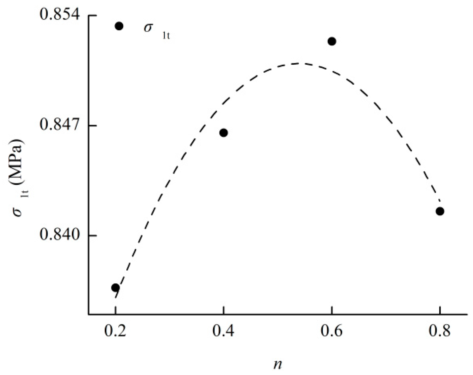
Figure 8.
Distribution of the strata in the coal mine.

Figure 9.
Schematic diagram of coalface in filling mining.

Figure 10.
Numerical model of the strata.

Figure 11.
The Z-direction displacement field of the strata (Y–Z profile at X of 80 m) when the goaf was filled with cemented rockfill with different granule gradations at a mining distance of 120 m. n = 0.2 (a); n = 0.4 (b); n = 0.6 (c); and, n = 0.8 (d).
Figure 11.
The Z-direction displacement field of the strata (Y–Z profile at X of 80 m) when the goaf was filled with cemented rockfill with different granule gradations at a mining distance of 120 m. n = 0.2 (a); n = 0.4 (b); n = 0.6 (c); and, n = 0.8 (d).


Figure 12.
Subsidence displacement of the coal seam roof at different mining distances when the goaf was filled with cemented rockfill with different granule gradations. n = 0.2 (a); n = 0.4 (b); n = 0.6 (c); and, n = 0.8 (d).
Figure 12.
Subsidence displacement of the coal seam roof at different mining distances when the goaf was filled with cemented rockfill with different granule gradations. n = 0.2 (a); n = 0.4 (b); n = 0.6 (c); and, n = 0.8 (d).

Figure 13.
Relationship between the maximum subsidence displacement of the coal seam roof and the Talbot index of the cemented rockfill at different mining distances.
Figure 13.
Relationship between the maximum subsidence displacement of the coal seam roof and the Talbot index of the cemented rockfill at different mining distances.

Figure 14.
Coupling effect of the cemented rockfill’s granule gradation and mining distance on the maximum subsidence displacement of the coal seam roof.
Figure 14.
Coupling effect of the cemented rockfill’s granule gradation and mining distance on the maximum subsidence displacement of the coal seam roof.

Figure 15.
The Z-direction stress field of the strata (Y-Z profile at X of 80 m) when the goaf was filled with cemented rockfill with different granule gradations at a mining distance of 120 m. n = 0.2 (a); n = 0.4 (b); n = 0.6 (c); and, n = 0.8 (d).
Figure 15.
The Z-direction stress field of the strata (Y-Z profile at X of 80 m) when the goaf was filled with cemented rockfill with different granule gradations at a mining distance of 120 m. n = 0.2 (a); n = 0.4 (b); n = 0.6 (c); and, n = 0.8 (d).


Figure 16.
Internal stress of the backfill at different mining distances when the goaf was filled by cemented rockfill with different granule gradations. n = 0.2 (a); n = 0.4 (b); n = 0.6 (c); and, n = 0.8 (d).
Figure 16.
Internal stress of the backfill at different mining distances when the goaf was filled by cemented rockfill with different granule gradations. n = 0.2 (a); n = 0.4 (b); n = 0.6 (c); and, n = 0.8 (d).

Figure 17.
Relationship between the maximum internal stress of the backfill and the Talbot index of the cemented rockfill at different mining distances.
Figure 17.
Relationship between the maximum internal stress of the backfill and the Talbot index of the cemented rockfill at different mining distances.

Figure 18.
Coupling effect of the cemented rockfill’s granule gradation and mining distance on the maximum internal stress of the backfill.
Figure 18.
Coupling effect of the cemented rockfill’s granule gradation and mining distance on the maximum internal stress of the backfill.

Figure 19.
Relationship between the maximum stress of the rock mass in the coalface and the Talbot index of the cemented rockfill at different mining distances.
Figure 19.
Relationship between the maximum stress of the rock mass in the coalface and the Talbot index of the cemented rockfill at different mining distances.
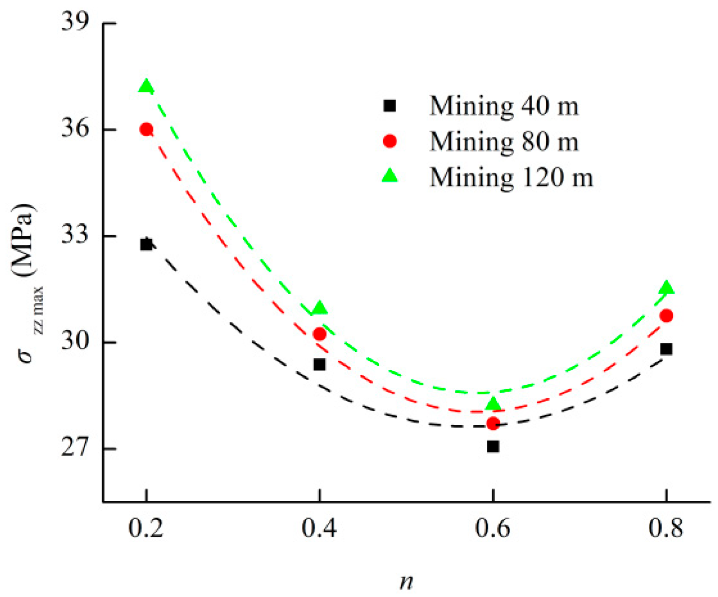
Figure 20.
Coupling effect of the cemented rockfill’s granule gradation and mining distance on the maximum stress of the rock mass in the coalface.
Figure 20.
Coupling effect of the cemented rockfill’s granule gradation and mining distance on the maximum stress of the rock mass in the coalface.
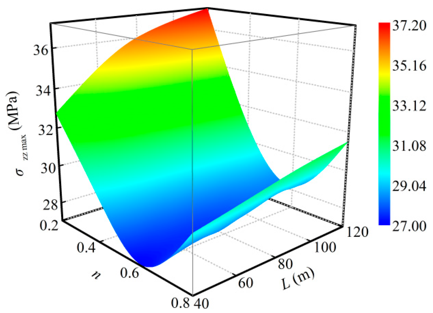
Figure 21.
The Z-direction displacement field of the strata (Y-Z profile at X of 80 m) at mining distances of 40 m to 80 m under fallen mining and filling mining with n = 0.6 cemented rockfill. Fallen mining at 40 m (a); Fallen mining at 80 m (b); Filling mining at 40 m (c); and, Filling mining at 80 m (d).


Table 1.
The chemical components of waste rock and composite Portland cement 32.5R.
| Varieties (%) | Al2O3 | CaO | Fe | Fe2O3 | K2O | MgO | Na2O | SiO2 | SO3 | TiO2 |
|---|---|---|---|---|---|---|---|---|---|---|
| Waste rock | 13.21 | 3.91 | 3.69 | - | 0.02 | 2.87 | - | 67.75 | - | - |
| P.C. 32.5R | 4.67 | 62.19 | - | 3.69 | 0.68 | 2.87 | 0.21 | 21.56 | 1.91 | 0.16 |
Table 2.
Distribution of particles under different Talbot indices.
| n | Mass (g) of Particles in Different Sizes (mm) | Mass Percent (%) of Particles in Different Sizes (mm) | ||||||||||||
|---|---|---|---|---|---|---|---|---|---|---|---|---|---|---|
| 0–0.5 | 0.5–1.0 | 1.0–1.5 | 1.5–2.5 | 2.5–5.0 | 5.0–8.0 | 8.0–10.0 | 0–0.5 | 0.5–1.0 | 1.0–1.5 | 1.5–2.5 | 2.5–5 | 5.0–8.0 | 8.0–10.0 | |
| 0.2 | 164.78 | 24.51 | 15.99 | 22.08 | 33.81 | 25.74 | 13.09 | 54.93 | 8.17 | 5.33 | 7.36 | 11.27 | 8.58 | 4.36 |
| 0.4 | 90.51 | 28.92 | 21.03 | 31.84 | 55.05 | 47.03 | 25.62 | 30.17 | 9.64 | 7.01 | 10.61 | 18.35 | 15.68 | 8.54 |
| 0.6 | 49.72 | 25.64 | 20.76 | 34.47 | 67.34 | 64.48 | 37.59 | 16.57 | 8.55 | 6.92 | 11.49 | 22.45 | 21.49 | 12.53 |
| 0.8 | 27.31 | 20.23 | 18.22 | 33.20 | 73.34 | 78.65 | 49.05 | 9.10 | 6.74 | 6.07 | 11.07 | 24.45 | 26.22 | 16.35 |
Table 3.
Experimental program for the production of the cemented rockfill specimen.
| Talbot Index | Type of Cementing Material | Content of Cementing Material m/g | Content of Distilled Water v/mL |
|---|---|---|---|
| 0.2 | Cement | 30 | 22.5 |
| 0.4 | Cement | 30 | 22.5 |
| 0.6 | Cement | 30 | 22.5 |
| 0.8 | Cement | 30 | 22.5 |
Table 4.
Relationships between the compressive strength and confining pressure.
| n | Relationship | Correlation Coefficient |
|---|---|---|
| 0.2 | σ1c = 1.9897σ3 + 1.6648 | 0.9043 |
| 0.4 | σ1c = 2.3832σ3 + 2.0175 | 0.8981 |
| 0.6 | σ1c = 2.3916σ3 + 2.0385 | 0.9461 |
| 0.8 | σ1c = 2.0791σ3 + 1.7497 | 0.9160 |
Table 5.
Relationships between the mechanical parameters and the Talbot index.
| Mechanical Parameter | Relationship | Correlation Coefficient |
|---|---|---|
| 0.9999 | ||
| 0.8232 | ||
| 0.9689 | ||
| 0.9577 | ||
| 0.9160 | ||
| 0.9719 | ||
| 0.9999 | ||
| 0.9934 | ||
| 0.8247 |
Table 6.
Model parameters of the strata.
| Strata | Height (m) | Density (kg/m−3) | Es (MPa) | μ | φ (°) | c (MPa) | σt (MPa) |
|---|---|---|---|---|---|---|---|
| Sandstone 1 | 2 | 2590 | 5300 | 0.28 | 34 | 9.5 | 6.1 |
| Mudstone 1 | 6 | 2460 | 3100 | 0.32 | 28 | 5.9 | 2.2 |
| Sandstone 2 | 6 | 2660 | 4600 | 0.27 | 37 | 9.7 | 6.6 |
| Mudstone 2 | 3 | 2470 | 3700 | 0.31 | 27 | 5.9 | 2.7 |
| Argillaceous sandstone 1 | 2 | 2550 | 4500 | 0.27 | 29 | 7.0 | 3.9 |
| Mudstone 3 | 3 | 2450 | 3800 | 0.30 | 28 | 5.9 | 2.8 |
| Argillaceous sandstone 2 | 2 | 2650 | 4900 | 0.27 | 32 | 13.8 | 7.7 |
| Coal | 4 | 1600 | 1910 | 0.33 | 22 | 2.5 | 1.5 |
| Mudstone 4 | 2 | 2500 | 3300 | 0.31 | 31 | 5.3 | 3.2 |
| Sandy mudstone | 2 | 2600 | 8900 | 0.28 | 33 | 6.9 | 4.3 |
| Sandstone 3 | 8 | 2700 | 13,200 | 0.25 | 36 | 12.8 | 7.5 |
| Limestone | 10 | 2750 | 27,900 | 0.22 | 47 | 15.9 | 9.5 |
Table 7.
Model parameters of the cemented rockfill with different granule gradations.
| Cemented Rockfill | Height (m) | Density (kg/m−3) | Es (MPa) | μ | φ (°) | c (MPa) | σt (MPa) |
|---|---|---|---|---|---|---|---|
| n = 0.2 | 4 | 1795 | 156.1705 | 0.1790 | 19.3317 | 0.5901 | 0.8367 |
| n = 0.4 | 4 | 1795 | 296.4508 | 0.1601 | 24.1322 | 0.6534 | 0.8466 |
| n = 0.6 | 4 | 1795 | 402.4365 | 0.1580 | 24.2242 | 0.6591 | 0.8524 |
| n = 0.8 | 4 | 1795 | 284.4737 | 0.1722 | 20.5154 | 0.6067 | 0.8416 |
Table 8.
Relationship between the maximum subsidence displacement of the coal seam roof and the Talbot index of the cemented rockfill at different mining distances.
Table 8.
Relationship between the maximum subsidence displacement of the coal seam roof and the Talbot index of the cemented rockfill at different mining distances.
| Mining Distance (MPa) | Relationship | Correlation Coefficient |
|---|---|---|
| 40 | Zmax = −0.4403n2 + 0.5100n − 0.2480 | 0.9770 |
| 80 | Zmax = −1.0968n2 + 1.2809n − 0.5250 | 0.9968 |
| 120 | Zmax = −1.4309n2 + 1.6766n − 0.6512 | 0.9997 |
Table 9.
Relationship between the maximum internal stress of the backfill and Talbot index of the cemented rockfill at different mining distances.
Table 9.
Relationship between the maximum internal stress of the backfill and Talbot index of the cemented rockfill at different mining distances.
| Mining Distance (MPa) | Relationship | Correlation Coefficient |
|---|---|---|
| 40 | σzz max = −20.9000n2 + 24.2344n + 1.9649 | 0.9776 |
| 80 | σzz max = −15.3538n2 + 17.9621n + 7.9208 | 0.9741 |
| 120 | σzz max = −12.4038n2 + 14.0005n + 10.0938 | 0.9962 |
Table 10.
Relationship between the maximum stress of the rock mass in the coalface and the Talbot index of the cemented rockfill at different mining distances.
Table 10.
Relationship between the maximum stress of the rock mass in the coalface and the Talbot index of the cemented rockfill at different mining distances.
| Mining Distance (MPa) | Relationship | Correlation Coefficient |
|---|---|---|
| 40 | σzz max = 38.3988n2 − 43.9721n + 40.2200 | 0.8551 |
| 80 | σzz max = 55.1113n2 − 64.2664n + 46.7808 | 0.9784 |
| 120 | σzz max = 59.5725n2 − 69.4488n + 48.8251 | 0.9988 |
© 2018 by the authors. Licensee MDPI, Basel, Switzerland. This article is an open access article distributed under the terms and conditions of the Creative Commons Attribution (CC BY) license (http://creativecommons.org/licenses/by/4.0/).
Share and Cite
MDPI and ACS Style
Wu, J.; Feng, M.; Xu, J.; Qiu, P.; Wang, Y.; Han, G. Particle Size Distribution of Cemented Rockfill Effects on Strata Stability in Filling Mining. Minerals 2018, 8, 407. https://doi.org/10.3390/min8090407
AMA Style
Wu J, Feng M, Xu J, Qiu P, Wang Y, Han G. Particle Size Distribution of Cemented Rockfill Effects on Strata Stability in Filling Mining. Minerals. 2018; 8(9):407. https://doi.org/10.3390/min8090407
Chicago/Turabian StyleWu, Jiangyu, Meimei Feng, Jingmin Xu, Peitao Qiu, Yiming Wang, and Guansheng Han. 2018. "Particle Size Distribution of Cemented Rockfill Effects on Strata Stability in Filling Mining" Minerals 8, no. 9: 407. https://doi.org/10.3390/min8090407
Note that from the first issue of 2016, this journal uses article numbers instead of page numbers. See further details here.