Estimates of scCO2 Storage and Sealing Capacity of the Janggi Basin in Korea Based on Laboratory Scale Experiments


1
Department of Earth Environmental Sciences, Pukyong National University, Busan 48513, Korea
2
BK21 Plus Project of the Graduate School of Earth Environmental Hazard System, Pukyong National University, Busan 48513, Korea
3
Department of Energy Resources Engineering, Pukyong National University, Busan 48513, Korea
*
Author to whom correspondence should be addressed.
Minerals 2019, 9(9), 515; https://doi.org/10.3390/min9090515
Submission received: 5 June 2019
/
Revised: 17 August 2019
/
Accepted: 19 August 2019
/
Published: 26 August 2019
(This article belongs to the Special Issue Geological and Mineralogical Sequestration of CO2)
Abstract
:Laboratory experiments were performed to measure the supercritical CO2 (scCO2) storage ratio (%) of conglomerate and sandstone in the Janggi Basin, which are classified as rock in Korea that are available for CO2 storage. The scCO2 storage capacity was evaluated by direct measurement of the amount of scCO2 replacing the pore water in each reservoir rock core. The scCO2 sealing capacity of the cap rock (i.e., tuff and mudstone) was also compared by measuring the scCO2 capillary entry pressure (Δp) into the rock core. The measured average scCO2 storage ratio of the conglomerate and the sandstone were 30.7% and 13.1%, respectively, suggesting that the scCO2 storage capacity was greater than 360,000 metric tons. The scCO2 capillary entry pressure for the tuff ranged from 15 to 20 bar and for the mudstone it was higher than 150 bar, suggesting that the mudstone layers had enough sealing capacity from the aspect of hydromechanics. From XRF analyses, before and after 90 d of the scCO2-water-cap rock reaction, the mudstone and the tuff were investigated to assure their geochemical stability as the cap rock. From the study, the Janggi Basin was considered an optimal CO2 storage site based on both its high scCO2 storage ratio and high capillary entry pressure.
1. Introduction
Eco-friendly plans and policies to reduce CO2 emission are being driven forward around the world. In developed countries, CO2 capture and sequestration (CCS) technology is partially commercialized and the total amount of subsurface CO2 storage has been on the rise [1,2,3,4]. Since the early 2000s, the government of South Korea has been working on several projects to determine the optimal CO2 storage sites on the Korean peninsula and the Janggi Basin. This basin is located in the southeastern part of the East Sea and is currently being evaluated for its potential to be one of the best onshore or offshore storage sites in Korea [5,6]. From geophysical and geological surveys, it is has become clear that the Miocene Janggi Basin consists of four small blocks (Guryongpo, Ocheon, Noeseongsan, and Yeongamri basins) [7]. The Noeseongsan block contains rudaceous sandstone and conglomerate layers that are considered promising for CO2 storage sites more than 800 m deep; these also have mudstone and dacitic tuff layers above them that are able to serve as stable shield layers [8,9]. The Korean government has a plan to inject a hundred thousand metric tons of CO2 in a pilot-scale onshore CO2 storage test site in 2030 and the Janggi Basin is considered a suitable place for the scCO2 storage test site. During stratigraphic analysis in 2015 and 2016, four sites in the Janggi Basin were drilled by the Korea Institute of Geoscience and Mineral Resources (KIGAM), and continuous drill cores to 1200 m in depth were collected at each site. From previously collected well logging data and the geo-structural interpretation results, the Janggi conglomerate formation in the Janggi Basin can be divided into four lithofacies. These consist of conglomerate and rudaceous sandstone from gravelly braided stream deposits, coarse sandstone deposited in mouth-bar or delta, muddy sandstone and shale deposited in floodplain environments, and mudstone as lacustrine deposits [8]. The western part of the basin is mainly composed of thick conglomerate and rudaceous sandstone lithofacies, which are available for use as a CO2 storage reservoir, whereas the mudstone and muddy sandstone lithofacies constitute the eastern part of the basin. The western part of the Janggi Basin has no large faults and is considered to be an optimal CO2 storage area. This area is now estimated to be at least about 10 km2, assuming that the practical volume of the CO2 storage volume in the Janggi Basin deeper than 800 m is about 0.025 km3 [8,9].
The estimation of the CO2 storage capacity of geological storage reservoirs is essential to determine reasonable CO2 storage site candidates and is directly dependent on the practical amount of scCO2 in non-aqueous phase, which can be stored in the pore spaces of the reservoir rock after scCO2 injection. The more water displaced by scCO2 in the void spaces of the reservoir rock, the more CO2 could be stored there. There are no exact definitions for scCO2 storage capacity yet, although there are several definitions of storage capacity from previous studies [10,11,12,13,14,15,16,17,18]. In recent research, the scCO2 storage capacity was generally defined as the proportion of the volume of scCO2 stored after injection, in relation to the pore volume of the CO2 reservoir rock [19,20]. Geological exploration and numerical simulation to determine the representative amount of scCO2 that could be stored within the pore spaces of a specific reservoir formation have been major subjects in CO2 sequestration (CS) studies.
However, the pore volume saturated with water was not fully replaced by scCO2 while injecting scCO2 into the reservoir rock and the practical scCO2 storage capacity for the specific reservoir rock can often be overestimated. The scCO2 displacement of water from pore spaces of the rock during scCO2 injection can be influenced by various parameters—Not just physical properties such as pore size, heterogeneity of the pore network, and injection pressure, but also mineralogical and geochemical reactivity. Thus, the best way to determine the amount of scCO2 storage possible in a specific rock formation is direct measurement of scCO2 displacement of water under scCO2 injection conditions. This occurs using rock cores at a laboratory scale, from which the results are extended to macro scale, including the entire reservoir formation [21,22].
The scCO2 storage ratio (%) (or “scCO2 displacement efficiency (%)”) of a reservoir formation is one of the most general parameters used in laboratory work for evaluating the CO2 storage amount of a formation [3,10,19,20]. The scCO2 storage ratio is defined as the fraction of the amount of scCO2 occupying pore spaces after scCO2 injection into a reservoir formation. It can be directly measured under scCO2 injection conditions simulated on a laboratory scale. In 2016, Wang et al. and Kim et al. [19,20] carried out direct laboratory measurement of the scCO2 storage ratio for possible reservoir rock cores, presenting the possibility that it might be used to estimate the scCO2 capacity for the specific reservoir. However, this process was still in the experimental stages and the number of studies on scCO2 storage capacity based on direct measurement in the laboratory are very limited. The CO2 storage capacity for a specific reservoir formation can be calculated by multiplying the scCO2 storage ratio by the total void volume of the formation, ignoring the amount of dissolved CO2. There are many benefits of direct measurement of the scCO2 storage ratio because it represents the substantive amount of CO2 retained in a specific storage formation, under the scCO2 injection condition. The estimation of the practical amount of CO2 storage for a specific reservoir rock could be made possible by using both the scCO2 storage ratio and the reservoir volume acquired from geological survey, which has almost never been tried before. In this study, laboratory experiments were performed to measure the amount of scCO2 displacing water from the pore spaces of the sandstones and conglomerate cores sampled from 800–1000 m depth in the Janggi Basin, which is classified as an available CO2 storage reservoir in Korea. The scCO2 storage capacity of the Janggi Basin was calculated quantitatively, according to the measured scCO2 storage ratio and with additional geophysical data on the spatial domain of the Janggi Basin.
The scCO2 sealing capacity of the cap rock is another major parameter used to select successful CO2 storage sites because it correlates to the leakage of scCO2 during the anticipated duration of CO2 sequestration. Even if a CO2 storage site has enough scCO2 storage capacity, it has to be excluded from suitable CO2 storage sites if the scCO2 leakage safety of the cap rock in the site is not assured. Layers of mudstone and dacitic tuff are repeated above the rudaceous sandstone and conglomerate layers in the Janggi Basin and it is assumed that they can play the role of cap rock to prevent the upward movement of scCO2 from deeper reservoir rock [9]. In 2017, the initial capillary entry pressure of scCO2 into the cap rock core surface, determined when the scCO2 began to infiltrate the rock, was successfully measured in the laboratory [23]. In this study, several experimental conditions for the capillary entry pressure measurement such as the boundary condition of the high-pressure tank and the scCO2 injection time on the core surface were modified, to more realistically simulate the scCO2 leakage at the boundary between the reservoir and the cap rock. More information for the comparison of the experimental conditions can be drawn from [23]. The scCO2 sealing capacity of the mudstone and dacitic tuff in the Janggi Basin was evaluated based on their initial scCO2 capillary entry pressures under simulated scCO2 injection P-T conditions. The change of mineralogical composition of the reservoir and cap rock after 90 d of scCO2–water–rock reaction at 50 °C and 100 bar was also investigated by XRF analysis. This was done to observe the effect of scCO2-related geochemical reactions on the sealing capacity. From the experimental results on the scCO2 storage ratio for the reservoir rock, on the initial scCO2 capillary entry pressure for the cap rock, and from mineralogical analyses for rock cores, the feasibility of the Janggi Basin as an available pilot-scale CO2 storage test site where a hundred thousand metric tons of CO2 could be injected was evaluated.
This study presents a novel and reliable method by which to select a successful CO2 storage site based on both quantitative scCO2 storage ratio and capillary entry pressure under CO2 sequestration conditions, as well as on geochemical analyses. The results of this study will also provide ideas for further quantitative research about the CO2 storage capacity and CO2 leakage safety based on practical measurements of the scCO2 storage ratio and initial scCO2 capillary entry pressure.
2. Materials and Methods
2.1. Preparation of the scCO2 Reservoir and Capping Rock Cores
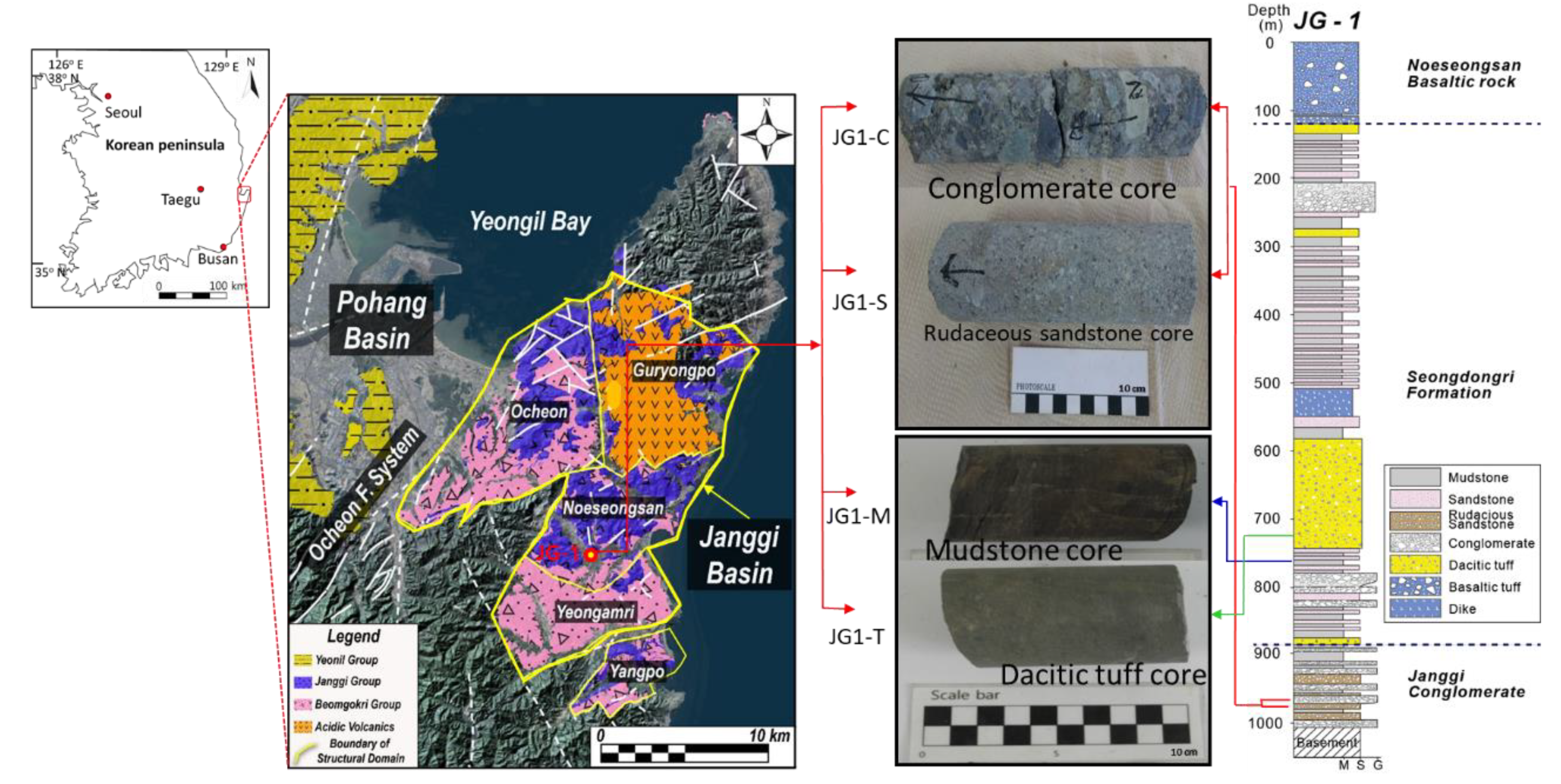
From the well logging data for four drilling sites in the Janggi Basin, rudaceous sandstone and conglomerate layers were considered available CO2 storage sites and the dacitic tuff and mudstone layers overlaying them as suitable cap rock [8,9]. Continuous drill cores (4.2 cm average diameter) from a drilling site 1200 m deep were acquired from KIGAM. From property analysis of these cores, three rudaceous sandstone cores (JG1-S1, JG1-S2, and JG1-S3; from 930–950 m) and three conglomerate cores (JG1-C1, JG1-C2, and JG1-C3; from 950–980 m) with average porosity of 14–18% were found and they were used for measurement of the scCO2 storage ratio. For the sealing cap rock, three mudstone cores (JG1-M1, JG1-M2, and JG1-M3; from 700–760 m) and three tuff cores (JG1-T1, JG1-T2, and JG1-T3; from 800–810 m) were used for the measurement of the initial scCO2 capillary entry pressure. Each rock core used in the experiment was cylindrical without cracks or fractures (4.2 cm diameter; length 5–7 cm). The geological map showing the area around the drilling site in the Janggi Basin and the rock cores used for the experiments are shown in Figure 1.
The CO2 storage and sealing capacity of rocks depend on physico-chemical properties such as porosity, permeability, reaction rate, and mineralogical stability. The porosity of the rock cores was measured using the vacuum saturation method suggested by the International Society for Rock Mechanics (ISRM) with vacuum pressure of 1 torr and vacuum time of 80 min. For each sandstone and conglomerate core, several thin slabs (1 cm × 1 cm × 0.2 cm each) were also prepared to identify the mineral composition of each core by modal analysis. To quantify the average mineral portion of each reservoir rock, 500 locations on each thin section surface of each rock slab were observed using a point-counter installed in a polarizing microscope. For each mudstone and tuff core, mineralogical and geochemical analyses were performed using XRD (X-Ray Diffractometer; X’Pert-MPD, Philips, Almelo, The Netherlands) and XRF (X-Ray Fluorescence Spectrometer; XRF-1800, Shimadzu, Kyoto, Japan), to determine their mineralogical properties.
2.2. Measurement of the scCO2 Storage Ratio for the Conglomerate and Sandstone Cores
When scCO2 was injected, water filling the void spaces of the reservoir rock was not fully replaced by the scCO2 because of the difference in interfacial tension between water and the scCO2 (or difference in wettability) [24]. Thus, the amount of scCO2 that could be stored in the subsurface reservoir rock was less than the total void space of the rock, and was affected by various physico-chemical parameters. For selection of an optimal CO2 storage site, the scCO2 storage capacity of rock from that specific reservoir should be estimated, based on the real scCO2 storage ratio. Moreover, the potential amount of storage for each kind of reservoir rock should also be determined before subsurface injection of the scCO2. Laboratory scale measurement of the scCO2 storage ratio, displacing water from the pore spaces of Janggi sandstone and conglomerate cores under the simulated scCO2 injection conditions was performed. The experimental conditions were maintained (50 °C and 100 bar) to simulate the CO2 storage conditions underground. The sandstone and conglomerate cores were cut (4.2 cm in diameter and 5–7 cm in length) and their cut surfaces were polished using powdered diamond paper to maintain a uniform scCO2 or water injection pressure on the cut surface. A high-pressure stainless-steel cell was developed to measure the amount of scCO2 stored in the pore spaces of each core after scCO2 injection. It is difficult to measure the scCO2 remaining in the pore space of the rock core after scCO2 injection because of the leakage of the injected scCO2 at the cylinder surface boundary between the cell inner wall and the rock-core wall surface. The high-pressure cell was designed with two different walls; the inner wall was composed of a thick rubber layer (1 cm thick) and the outer wall of stainless steel. The space between the inner and the outer wall of the cell was sealed with pressurized water, which was injected from outside the cell. The surface of the inner rubber wall was in tight contact with the rock core cylinder surface, when the water pressure in the space was much higher than the scCO2 injection pressure (Δp > 100 bar). The rock core top and bottom head surfaces were held using a screw-type steel holder with a hole in the middle for scCO2 or water injection/drainage in the rock core. It was possible to shut off the bypass of injected scCO2 or pore water through the boundary between the core cylinder surface and the cell inner wall, allowing the scCO2 (or water) to flow only through pore spaces within the rock core. Figure 2 shows photographs of the high-pressure cell and the schematic diagram for the cross-section of the cell used in the experiment.
For the experiment, each core was fully dried at 50 °C in an oven and then weighed. The dried core was fixed by two core holders inside the high-pressure stainless-steel cell. The outer wall of the high-pressure cell was covered by a heating jacket to maintain the cell wall at the cell temperature of 50 °C. Distilled water was injected into the sealed space between the inner wall and the outer wall of the cell by a syringe pump (Isco-D260; Teledyne Isco, Inc., Nebraska, NE, USA), which was maintained at 300–350 bar. Then, the distilled water was flushed through the core at 100 bar (the injection pressure) for three pore volumes of the core to fully saturate the core with water. Next, scCO2 was injected through the influent opening into the cell to displace water from the pore spaces of the core at 110 bar (Δp = 10 bar between the injection pressure and the pore water pressure in the core), while more than two pore volumes of scCO2 were flushed from the core at 110 bar (assuming that displacement of water by the scCO2 was successful within a few days). All of the effluent water was stored in a small stainless storage cell and its mass was weighed to measure the amount of water displaced by the scCO2 in the rock core. A high-pressure stainless-steel chamber (5 L capacity) was connected to the effluent of the cell to consider the boundary condition of the reservoir rock when the scCO2 was flushed from the rock core in the experiment. The water in the pores was compressed as the pore pressure increased due to scCO2 injection and enough water or scCO2 volume had to be provided in the chamber for the replacement of all the scCO2 during the experiment. All of the high-pressure cells were maintained at 50 °C and 110 bar, after the CO2 injection, to simulate the subsurface CO2 storage conditions. Figure 3 shows the procedure of the experiment for scCO2 exchange in the rock core.
When the amount of water drained from the core was measured, the scCO2 storage ratio for the specific rock core under the scCO2 injection condition (in this case, 100 bar and 50 °C) could be calculated using Equation (1).
where Ws is the volume of water saturating the core and Wout is the water volume displaced by scCO2 during the scCO2 injection.
From Equation (1), the scCO2 storage capacity of the conglomerate and the sandstone formations in the Janggi Basin were estimated via Equation (2) with the volume of the stratum, the average porosity, the specific gravity of the scCO2, and the storage ratio of scCO2 [3,14].
where V is the volume of the conglomerate or sandstone layer (estimated from the previous geological survey data), φ is the average porosity, ρ is the specific gravity of the scCO2, and ε is the scCO2 storage ratio. The feasibility of the Janggi Basin as a CO2 reservoir formation was evaluated based on the scCO2 storage capacity of rudaceous sandstone and conglomerate drill core samples from the Janggi Basin (total of six cores).
2.3. Measurement of the Initial scCO2 Capillary Entry Pressure for Mudstone and Dacitic Tuff
When scCO2 is injected into reservoir rock, it is distributed as a separate phase from water in pore spaces and begins to move slowly upward from the lower part of the reservoir rock, due to buoyant force, because of its lower density as compared to water. Some of the injected scCO2 might reach the boundary between the cap rock and the reservoir rock during continuous injection. At the early stage of scCO2 injection, the amount of scCO2 reaching the boundary is not much and the cap rock can prevent the intrusion of scCO2 because of its low permeability. As the amount of scCO2 at the boundary and its buoyant pressure increase because of continuous scCO2 injection, advective and the diffusive intrusion of scCO2 into the cap rock occurs. This pressure initiates seepage of the scCO2 from the reservoir rock, threatening the leakage safety of the CO2 storage site. The sealing capacity of the cap rock is directly dependent on the initial scCO2 seepage (or intrusion) pressure on the cap rock surface [22]. The direct measurement of the initial scCO2 capillary entry pressure of the cap rock was performed at a laboratory scale, to evaluate the scCO2 shielding capacity of the cap rocks in the study area. The mudstone and dacitic tuff rock cores sampled during the deep drilling expedition (from 700–800 m) at the onshore site in the Janggi Basin were used for the experiment (Figure 1).
Rock cores without cracks or fractures were cut (4.2 cm diameter, 5–6 cm length) and were then fully dried at 50 °C in an oven for 7 d. Each rock core was fixed in the high-pressure stainless-steel cell (which was used in the same way as in the previous experiment, Section 2.2). Each core was saturated with distilled water at 100 bar of pore water pressure. The effluent of the cell was connected to a large tank filled with 3 L of water and 2 L of scCO2 at 100 bar and 50 °C, simulating the subsurface scCO2 injection conditions. The initial scCO2 capillary entry pressure into the rock core head (higher than 100 bar: Δp = injection pressure − 100 bar), was controlled at the influent port with the regulator of the core holder in the cell bottom, until the scCO2 began to penetrate the rock. The scCO2 injection pressure was set at 110 bar and the injection pressure was increased by 10 bar until the scCO2 began to penetrate the rock core head. At the outset, the scCO2 injection pressure on the core head surface was set at 110 bar (Δp = 10 bar) and any scCO2 intrusion into the core was observed for 10 days. If no scCO2 intrusion occurred, the injection pressure was increased by 10 bar for 10 more days, to monitor any scCO2 intrusion into the core. This process was repeated until the scCO2 began to penetrate the rock core head. When the scCO2 begin to intrude and the scCO2 injection pressure started to decrease, the scCO2 injection pressure was maintained until scCO2 was flushed from the end of the rock core. This pressure was regarded as the initial scCO2 capillary entry pressure (Δp) of the rock core. The scCO2 shield capacity of each kind of cap rock core (dacitic tuffs and mudstones here) was evaluated by comparing their initial scCO2 capillary entry pressures (Δp).
The mineralogical changes of mudstone and tuff were also measured to evaluate their geochemical stability for 90 d of the scCO2–water–rock reaction under CO2 storage conditions (100 bar and 50 °C). The rock core was pulverized using a mortar, and ten grams of powdered rock materials were mixed with 100 mL of distilled water in a high-pressure stainless-steel cell (capacity of 150 mL), in which the inner wall was coated with a Teflon layer. The void spaces in the cell were filled with scCO2 using a syringe pump. Then scCO2–water–rock reactions were allowed to occur in the cell at 100 bar and 50 °C, simulating the subsurface storage conditions. The total reaction time was 90 d and XRD analysis was conducted before and after the reaction to identify any mineralogical changes of the cap rock due to the scCO2–water–rock reaction.
3. Results and Discussion
3.1. Measurement of the scCO2 Storage Ratio for the Conglomerate and Sandstone Cores
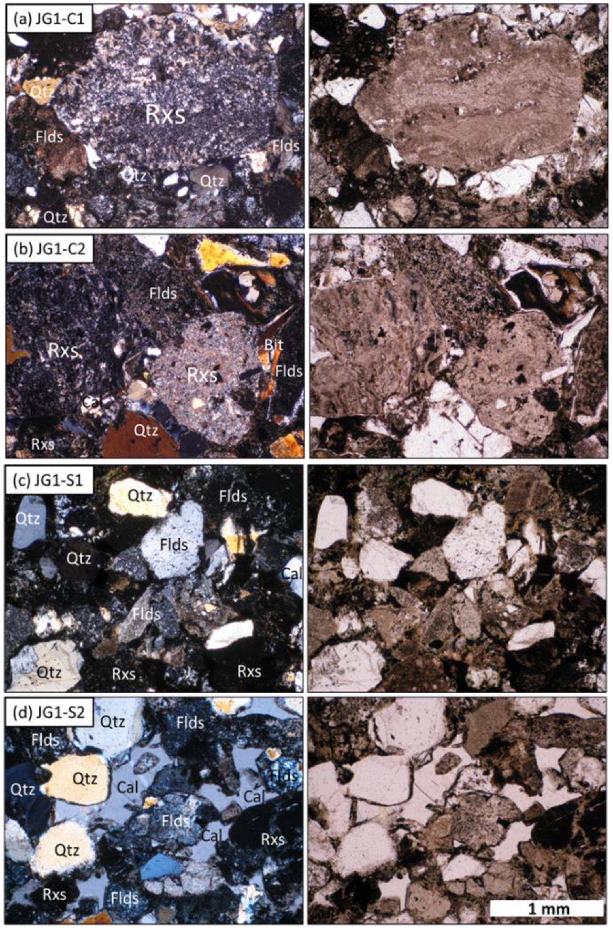
Results of the modal analyses for the rudaceous sandstone and conglomerate cores are shown in Table 1 and the photomicrographs of their thin sections are shown in Figure 4. The conglomerate was mostly composed of rhyrolitic and andesitic rock fragments (average 74.5%), followed by quartz, clay/accessory minerals, feldspar, micas, and calcite (in descending order). The sandstone mainly consisted of quartz, rock fragments, clay/accessory minerals, feldspar, micas, and calcite. Their average proportions were 32.5%, 23.8%, 18.3%, 19.4%, 2.5%, and 2.5%, respectively (Table 1). In previous studies it was observed that calcite, feldspars, chlorite, micas, and clay minerals bearing Ca and Mg might control the geochemical reactions with CO2 in the storage site, thereby regulating the physical properties of the reservoir rock [25,26,27,28]. The results from the XRD analyses (not shown in this paper) showed a mineral composition similar to that indicated by the modal analysis.
The porosity of the conglomerate and the sandstone cores were measured and are shown in Table 2. The average porosity of the conglomerate and the rudaceous sandstone was 17.8% and 14.5%, respectively, suggesting that they fall within the porosity range of typical CO2 storage formations in other places, where large amounts of scCO2 have been injected [22,29,30,31,32,33,34]. The scCO2 storage ratio of each conglomerate and sandstone core was measured and their averages are shown in Table 2. The calculated average scCO2 storage ratio of the Janggi conglomerates was 30.7%, suggesting that 30.7% of the void space in the conglomerate was filled with scCO2, while the pressure difference between the scCO2 injection and the pore water was maintained at 10 bar. The average scCO2 storage ratio of rudaceous sandstones was 13.0%, which was about two-fifths that of the conglomerate. From these results, both kinds of rock had great capability for storing CO2 in their pore spaces, but the conglomerate was considered to be a better option for a CO2 storage site than the rudaceous sandstone.
The scCO2 storage ratio values were used for the estimation of the CO2 storage capacity for the Janggi Basin (Table 3). From previous studies [7,8,9] it was known that the Janggi Basin extends horizontally over about 0.25 km2 below a depth of 800 m and that the thickness of both the conglomerate and sandstone layers available for the CO2 reservoir is 100 m (about 1:1 ratio), assuming that the maximum volume of the CO2 storage formation in the Janggi Basin under 800 m in depth is about 0.025 km3. The parameter values used to calculate the CO2 storage capacity and the calculated scCO2 capacity for the two formations are shown in Table 3. The scCO2 storage capacity of the reservoir rocks around the probable scCO2 injection site in Janggi Basin was calculated to be 368,742 metric tons, demonstrating that the conglomerate and sandstone formations in Janggi Basin have great potential for use as a pilot test site for CO2 storage in Korea (to receive more than 100,000 metric tons of CO2 injection at the test storage site). As mentioned earlier, the amount of dissolved CO2 in the pore water of each core was ignored while calculating the amount of scCO2 storage in Table 3. When the amount of dissolved CO2 in the pore water was considered, the already substantial CO2 storage capacity of the Janggi Basin was increased. Thus, if enough scCO2 was secured in the conglomerate and the sandstones, the Janggi Basin could be evaluated as a positive storage site, regardless of the amount of CO2 dissolved in the pore water.
3.2. Measurement of the Initial scCO2 Capillary Entry Pressure for Mudstone and Dacitic Tuff
The mineralogical changes of the mudstone and the dacitic tuff after 90 days of scCO2–water–rock reaction were investigated by XRF analyses and their results are shown in Table 4. The results indicated that even after 90 d of reaction, the proportions of the major constituents of the two kinds of rock were not significantly changed, except for a minor decrease of SiO2 and CaO. These originated from increased dissolution of calcite, Ca–feldspar, and Ca-bearing silicates, which were similar to results of previous studies [37,38,39]. It is suggested that the mudstone and the dacitic tuff in the Janggi Basin is likely to maintain significant stability against scCO2-involved geochemical reactions during CO2 storage.
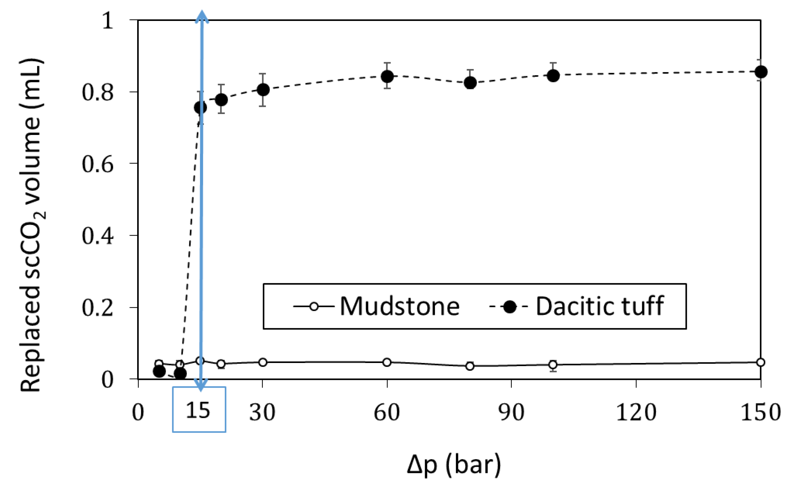
Results from the measurement of the initial scCO2 capillary entry pressure (Δp) for the mudstone and the tuff core are shown in Figure 5. For all of tuff cores, the scCO2 began to intrude into the rock core at 115 bar (Δp = 15 bar) and continuous scCO2 injection into the core occurred at a Δp higher than 20 bar. This suggests that the initial scCO2 capillary entry pressure (Δp) of the dacitic tuff ranged from 15 to 20 bar, under the conditions of 100 bar and 50 °C. In the tuff cores, 8–10% of the void space (0.7–0.9 mL) was filled by scCO2 at a Δp higher than 20 bar. In a previous study (Kim et al. 2019), the average initial scCO2 capillary entry pressure of the sandstone and the conglomerate in the Janggi Basin was lower than 10 bar (mostly < 5 bar), which was less than one-third that for the dacitic tuff. For the mudstone cores in the Janggi Basin, the scCO2 did not penetrate the core surface and the stored scCO2 was less than 0.005 mL, even when the injection pressure was 250 bar (Δp = 150 bar) for 30 d. This suggests that the initial scCO2 capillary entry pressure for the mudstone core was much higher than 150 bar (10 times higher than for the tuff). Based on the initial scCO2 capillary entry pressure, the mudstone formation in the Janggi Basin was much more suitable than the tuff formation as a shield against scCO2 leakage from the reservoir rock.
4. Conclusions
Determining an optimal storage site and choosing the main parameters to be considered has been one of the main issues for the geological sequestration of CO2. During the last two decades, evaluation of the storage capacity and the leakage safety has been considered essential for optimal storage site selection. However, previously, only rough estimations were made of the reservoir and the capping rock using conventional parameters such as porosity and permeability, or by using large-scale information acquired from geophysical exploration and geological field observation. The quantitative evaluation of CO2 storage capacity and of the risk of CO2 leakage has been very limited, even at a laboratory scale. Recently, a direct technique for the measurement of the scCO2 storage ratio and the initial scCO2 capillary pressure of the rock was developed, but its application to CO2 storage site selection has almost never been attempted in previous studies. As mentioned earlier, the Janggi Basin was selected as a feasibility testing site to store at least 100,000 metric tons of CO2 before starting large-scale injection (more than 1,000,000 metric tons) on the Korean peninsula. For the testing site, it was important that the CO2 storage capacity of the Janggi Basin was, at the least, larger than 100,000 metric tons. This study presents an easy and effective technique by which to evaluate the CO2 capacity of reservoir rock and the leakage safety of the cap rock, and finally, to successfully select the Janggi basin as an optimal CO2 storage site in Korea. The scale-up estimation of the CO2 storage capacity for the conglomerate and the rudaceous sandstone in the Janggi Basin of Korea was performed on the basis of direct measurement of the scCO2 storage ratio. The safety risk of scCO2 leakage for the cap rock of dacitic tuff and mudstone in the Janggi Basin was also quantitatively evaluated by measuring the initial scCO2 capillary entry pressure.
The experimental results successfully demonstrated that the conglomerate and sandstone formations of the Janggi Basin are suitable as a geological storage test site, for injection of a hundred thousand tons of CO2 from the viewpoint of storage capacity. If the amount of dissolved CO2 in the pore water could be considered, a more precise estimate of the CO2 storage capacity for the specific reservoir formation could be estimated; related research in this area is already in progress.
It was also verified that the mudstone formation in the Janggi Basin is adequate to prevent the seepage of buoyant scCO2 from the reservoir site because its initial capillary entry pressure (Δp) was higher than 150 bar. From the XRF analysis before and after the experiment, reliable evidence for the geochemical stability of the tuff and the mudstone was also provided. These quantitative measurements of the scCO2 storage ratio and the initial scCO2 capillary entry pressure applied in this study could be used to determine practical CO2 storage sites and could also provide meaningful information for future decisions regarding scCO2 injection conditions.
This study focused on the hydromechanical measurement of the scCO2 in the pore spaces of rock core, over just a few months and, thus, did not deal with the effect of geochemical reactions (CO2–water–rock) on the scCO2 capacity and the capillary entry pressure with a long-term view. Recent research indicates that physical or chemical changes in the properties of rock involved in CO2 sequestration could arise from mineralogical or geochemical reactions within a shorter time after CO2 injection, than previously expected. For successful selections of optimal CO2 storage subsurface sites, the geochemical stability of reservoir or cap rocks should be considered an important parameter, along with the storage capacity and the capillary entry pressure.
Author Contributions
M.L. and J.P. conceived and designed the methodology and the experiments; J.P., M.L., and S.K. performed the experiments and the data analyses; S.W. and M.Y. contributed materials and data interpretation; M.L. wrote the paper to prepare the submission.
Funding
This research was supported by the Korea Agency for Infrastructure Technology Advancement (KAIA) grant funded by the Ministry of Land, Infrastructure and Transport (Grant 19CTAP-C151965-01) and by the grant (2019002470002) from Korea Ministry of Environment as “The SEM (Subsurface Environmental Management) projects”.
Acknowledgments
The authors would like to express their gratitude to the anonymous reviewers for their critical comments and advice.
Conflicts of Interest
The authors declare no conflict of interest.
References
- Michael, K.; Golab, A.; Shulakova, V.; Ennis-King, J.; Allinson, G.; Sharma, S.; Aiken, T. Geological storage of CO2 in saline aquifers—A review of the experience from existing storage operations. Int. J. Greenh. Gas Control 2010, 4, 659–667. [Google Scholar] [CrossRef]
- Leung, D.Y.C.; Caramanna, G.; Maroto-Valer, M.M. An overview of current status of carbon dioxide capture and storage technologies. Renew. Sustain. Energy Rev. 2014, 39, 426–443. [Google Scholar] [CrossRef] [Green Version]
- Bachu, S. Review of CO2 storage efficiency in deep saline aquifers. Int. J. Greenh. Gas Control 2015, 40, 188–202. [Google Scholar] [CrossRef]
- IPCC Special Report on the Impacts of Global Warming of 1.5 °C above Pre-Industrial Levels and Related Global Greenhouse Gas Emission Pathways, in the Context of Strengthening the Global Response to the Threat of Climate Change, Sustainable Development, and Efforts to Eradicate Poverty; IPCC: Incheon, Korea, 2018.
- Kim, M.-C.; Kim, J.-S.; Jung, S.; Son, M.; Sohn, Y.K. Bimodal volcanism and classification of the Miocene basin fill in the northern area of the Janggi-myeon, Pohang, Southeast Korea. J. Geol. Soc. Korea 2011, 47, 585–612. [Google Scholar]
- Song, C.W. A study on potential geologic facility sites for carbon dioxide storage in the Miocene Pohang Basin, SE Korea. J. Geol. Soc. Korea 2015, 51, 53–66. [Google Scholar] [CrossRef]
- Kim, M.-C.; Gihm, Y.S.; Son, E.-Y.; Son, M.; Hwang, I.G.; Shinn, Y.J.; Choi, H. Assessment of the potential for geological storage of CO2 based on its structural and sedimentologic characteristics in the Miocene Janggi Basin, SE Korea. J. Geol. Soc. Korea 2015, 51, 253–271. [Google Scholar] [CrossRef]
- Gu, H.-C.; Hwang, I.G. Depositional history of the Janggi Conglomerate controlled by tectonic subsidence, during the early stage of Janggi Basin evolution. J. Geol. Soc. Korea 2017, 53, 221–240. [Google Scholar] [CrossRef]
- Gu, H.-C.; Gim, J.-H.; Hwang, I.G. Variation in depositional environments controlled by tectonics and volcanic activities in the lower part of the Seongdongri Formation, Janggi Basin. J. Geol. Soc. Korea 2018, 54, 21–46. [Google Scholar] [CrossRef]
- Bachu, S.; Bonijoly, D.; Bradshaw, J.; Burruss, R.; Holloway, S.; Christensen, N.P.; Mathiassen, O.M. CO2 storage capacity estimation: Methodology and gaps. Int. J. Greenh. Gas Control 2007, 1, 430–443. [Google Scholar] [CrossRef]
- Lindeberg, E.; Vuillaume, J.F.; Ghaderi, A. Determination of the CO2 storage capacity of the Utsira formation. Energy Procedia 2009, 1, 2777–2784. [Google Scholar] [CrossRef]
- Kopp, A.; Class, H.; Helmig, R. Investigations on CO2 storage capacity in saline aquifers. Part 1. Dimensional analysis of flow processes and reservoir characteristics. Int. J. Greenh. Gas Control 2009, 3, 263–276. [Google Scholar] [CrossRef]
- Pingping, S.; Xinwei, L.; Qiujie, L. Methodology for estimation of CO2 storage capacity in reservoirs. Pet. Explor. Dev. 2009, 36, 216–220. [Google Scholar] [CrossRef]
- Goodman, A.; Hakala, A.; Bromhal, G.; Deel, D.; Rodosta, T.; Frailey, S.; Small, M.; Allen, D.; Romanov, V.; Fazio, J.; et al. U.S. DOE methodology for the development of geologic storage potential for carbon dioxide at the national and regional scale. Int. J. Greenh. Gas Control 2011, 5, 952–965. [Google Scholar] [CrossRef]
- Knopf, S.; May, F. Comparing methods for the estimation of CO2 storage capacity in saline aquifers in Germany: Regional aquifer based vs. structural trap based assessments. Energy Procedia 2017, 114, 4710–4721. [Google Scholar] [CrossRef]
- Elenius, M.; Skurtveit, E.; Yarushina, V.; Baig, I.; Sundal, A.; Wangen, M.; Landschulze, K.; Kaufmann, R.; Choi, J.C.; Hellevang, H.; et al. Assessment of CO2 storage capacity based on sparse data: Skade Formation. Int. J. Greenh. Gas Control 2018, 79, 252–271. [Google Scholar] [CrossRef]
- Doughty, C.; Pruess, K.; Benson, S.; Hovorka, S.D.; Knox, P.R.; Green, C.P. Capacity investigation of brine-bearing sands of the Frio formation for geologic sequestration of CO2. Lawrence Berkeley Natl. Lab. 2001. Available online: http://hdl.handle.net/2152/64418 (accessed on 26 August 2019).
- Zhou, Q.; Birkholzer, J.T.; Tsang, C.F.; Rutqvist, J. A method for quick assessment of CO2 storage capacity in closed and semi-closed saline formations. Int. J. Greenh. Gas Control 2008, 2, 626–639. [Google Scholar] [CrossRef]
- Wang, S.; Kim, J.; Lee, M. Measurement of the scCO2 storage ratio for the CO2 reservoir rocks in Korea. Energy Procedia 2016, 97, 342–347. [Google Scholar] [CrossRef]
- Kim, S.; Kim, J.; Lee, M.; Wang, S. Evaluation of the CO2 storage capacity by the measurement of the scCO2 displacement efficiency for the sandstone and the conglomerate in Janggi Basin. Econ. Environ. Geol. 2016, 49, 469–477. [Google Scholar] [CrossRef]
- Annual Report 2008: NETL (National Energy Technology Laboratory) Carbon Sequestration ATLAS of the United States and Canada; DOE: Washington, DC, USA, 2008.
- Tasianas, A.; Koukouzas, N. CO2 storage capacity estimate in the lithology of the mesohellenic trough, Greece. Energy Procedia 2016, 86, 334–341. [Google Scholar] [CrossRef]
- An, J.; Lee, M.; Wang, S. Evaluation of the sealing capacity of the supercritical CO2 by the measurement of its injection pressure into the tuff and the mudstone in the Janggi Basin. Econ. Environ. Geol. 2017, 50, 303–311. [Google Scholar]
- Iglauer, S. Optimum storage depths for strucural CO2 trapping. Int. J. Greenh. Gas Control 2018, 77, 82–87. [Google Scholar] [CrossRef]
- Gaus, I. Role and impact of CO2-rock interactions during CO2 storage in sedimentary rocks. Int. J. Greenh. Gas Control 2010, 4, 73–89. [Google Scholar] [CrossRef]
- Park, J.; Baek, K.; Lee, M.; Wang, S. Physical property changes of sandstones in Korea derived from the supercritical CO2–sandstone–groundwater geochemical reaction under CO2 sequestration condition. Geosci. J. 2015, 19, 313–324. [Google Scholar] [CrossRef]
- Jun, Y.S.; Giammar, D.E.; Werth, C.J. Impacts of geochemical reactions on geologic carbon sequestration. Environ. Sci. Technol. 2013, 47, 3–8. [Google Scholar] [CrossRef]
- Park, J.; Baek, K.; Lee, M.; Chung, C.-W.; Wang, S. The use of the surface roughness value to quantify the extent of supercritical CO2 involved geochemical reaction at a CO2 sequestration site. Appl. Sci. 2017, 7, 572. [Google Scholar] [CrossRef]
- IPCC Special Report on Carbon Dioxide Capture and Storage. Prepared by Working Group III of the Intergovernmental Panel on Climate Change; Cambridge University Press: Lodon, UK, 2005. [Google Scholar]
- Bachu, S.; Gunter, W.D.; Perkins, E.H. Aquifer disposal of CO2: Hydrodynamic and mineral trapping. Energy Convers. Manag. 1994, 35, 269–279. [Google Scholar] [CrossRef]
- Wigand, M.; Carey, J.W.; Schütt, H.; Spangenberg, E.; Erzinger, J. Geochemical effects of CO2 sequestration in sandstones under simulated in situ conditions of deep saline aquifers. Appl. Geochem. 2008, 23, 2735–2745. [Google Scholar] [CrossRef]
- Zhao, J.; Lu, W.; Zhang, F.; Lu, C.; Du, J.; Zhu, R.; Sun, L. Evaluation of CO2 solubility-trapping and mineral-trapping in microbial-mediated CO2–brine–sandstone interaction. Mar. Pollut. Bull. 2014, 85, 78–85. [Google Scholar] [CrossRef]
- Dawson, G.K.W.; Pearce, J.K.; Biddle, D.; Golding, S.D. Experimental mineral dissolution in Berea Sandstone reacted with CO2 or SO2–CO2 in NaCl brine under CO2 sequestration conditions. Chem. Geol. 2015, 399, 87–97. [Google Scholar] [CrossRef]
- Mediato, J.F.; García-Crespo, J.; Izquierdo, E.; García-Lobón, J.L.; Ayala, C.; Pueyo, E.L.; Molinero, R. Three-dimensional reconstruction of the caspe geological structure (Spain) for evaluation as a potential CO2 storage site. Energy Procedia 2017, 114, 4486–4493. [Google Scholar] [CrossRef]
- Span, R.; Wagner, W. A new equation of state for carbon dioxide covering the fluid region from the triple-point temperature to 1100 K at pressures up to 800 MPa. J. Phys. Chem. Ref. Data 1996, 25, 1509–1596. [Google Scholar] [CrossRef]
- Spycher, N.; Pruess, K. CO2–H2O mixtures in the geological sequestration of CO2. II. Partitioning in chloride brines at 12–100 °C and up to 600 bar. Geochim. Cosmochim. Acta 2005, 69, 3309–3320. [Google Scholar] [CrossRef]
- Sendula, E.; Páles, M.; Szabó, B.P.; Udvardi, B.; Kovács, I.; Kónya, P.; Freiler, Á.; Besnyi, A.; Király, C.; Székely, E.; et al. Experimental study of CO2-saturated water-illite/kaolinite/montmorillonite system at 70–80 °C, 100–105 bar. Energy Procedia 2017, 114, 4934–4947. [Google Scholar] [CrossRef]
- Rezaee, R.; Saeedi, A.; Iglauer, S.; Evans, B. Shale alteration after exposure to supercritical CO2. Int. J. Greenh. Gas Control 2017, 62, 91–99. [Google Scholar] [CrossRef]
- Luo, X.; Ren, X.; Wang, S. Supercritical CO2–water–shale interactions under supercritical CO2 simulation conditions. Energy Procedia 2018, 144, 182–185. [Google Scholar] [CrossRef]
Figure 1.
Geological map of the area around the drilling site (JG-1: ![Minerals 09 00515 i001]() ) in the Janggi Basin, Korea, photographs of rock cores used for the experiment and the stratigraphic columnar section (from left to right) used for the experiment (modified from [7,8]).
) in the Janggi Basin, Korea, photographs of rock cores used for the experiment and the stratigraphic columnar section (from left to right) used for the experiment (modified from [7,8]).
 ) in the Janggi Basin, Korea, photographs of rock cores used for the experiment and the stratigraphic columnar section (from left to right) used for the experiment (modified from [7,8]).
Figure 2.
Photograph of the high-pressure cell used for the experiment to measure the supercritical CO2 (scCO2) storage ratio.
Figure 2.
Photograph of the high-pressure cell used for the experiment to measure the supercritical CO2 (scCO2) storage ratio.
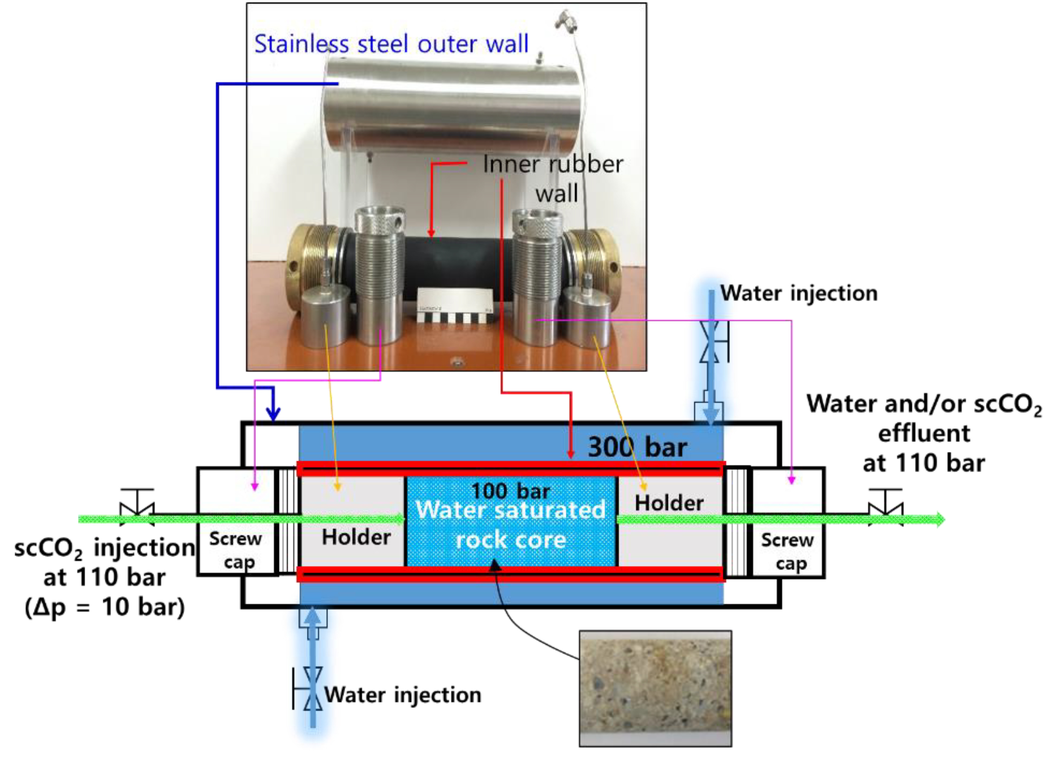
Figure 3.
Schematic of the experiment to measure the scCO2 storage ratio.

Figure 4.
Photomicrographs of thin sections of the conglomerate (a,b) and the rudaceous sandstone (c,d); left column—closed mode; right column—open mode; Qtz—quartz; Flds—feldspars; Cal—calcite; Bit—biotite; and Rxs—rock fragments.
Figure 4.
Photomicrographs of thin sections of the conglomerate (a,b) and the rudaceous sandstone (c,d); left column—closed mode; right column—open mode; Qtz—quartz; Flds—feldspars; Cal—calcite; Bit—biotite; and Rxs—rock fragments.

Figure 5.
Initial scCO2 capillary entry pressure (Δp) and the volume of scCO2 stored in mudstone and dacitic tuff cores.
Figure 5.
Initial scCO2 capillary entry pressure (Δp) and the volume of scCO2 stored in mudstone and dacitic tuff cores.


Table 1.
Petrographic detrital modal analysis of the rock cores.
| Rock Type | Mineral Portion (%) | |||||||
|---|---|---|---|---|---|---|---|---|
| Quartz | K-Feldspar | Plagioclase | Rock Fragment | Fine Matrix and Clay | Calcite | Micas | Others | |
| JG1-C1 | 7.8 | 1.8 | 1.2 | 80.6 | 8.0 | 0.2 | 0.0 | 0.4 |
| JG1-C2 | 17.8 | 6.6 | 4.8 | 57.4 | 10.8 | 0.4 | 1.2 | 1.0 |
| JG1-C3 | 6.4 | 1.8 | 1.0 | 85.4 | 3.8 | 0.4 | 0.4 | 0.8 |
| Average ± standard deviation | 10.7 ± 6.2 | 3.4 ± 2.8 | 2.3 ± 2.1 | 74.5 ± 15.0 | 7.5 ± 3.5 | 0.3 ± 0.1 | 0.5 ± 0.6 | 0.7 ± 0.3 |
| JG1-S1 | 33.6 | 8.8 | 12.0 | 24.8 | 16.0 | 2.2 | 1.2 | 1.4 |
| JG1-S2 | 31.6 | 11.6 | 8.2 | 24.2 | 18.4 | 0.6 | 4.4 | 1.0 |
| JG1-S3 | 32.2 | 10.4 | 7.0 | 22.4 | 20.4 | 4.6 | 1.8 | 1.2 |
| Average ± standard deviation | 32.5 ± 1.0 | 10.3 ± 1.4 | 9.1 ± 2.6 | 23.8 ± 1.2 | 18.3 ± 2.2 | 2.5 ± 2.0 | 2.5 ± 1.7 | 1.2 ± 0.2 |
| JG1-M1 | 40.8 | 3.0 | 1.4 | 0.4 | 47.4 | 1.2 | 2.6 | 3.2 |
| JG1-M2 | 43.8 | 2.8 | 0.6 | 0.0 | 47.4 | 0.4 | 2.4 | 2.6 |
| JG1-M3 | 33.6 | 2.4 | 0.4 | 0.2 | 58.6 | 0.2 | 2.2 | 2.4 |
| Average ± standard deviation | 39.4 ± 5.2 | 2.7 ± 0.3 | 0.8 ± 0.5 | 0.2 ± 0.2 | 51.1 ± 6.5 | 0.6 ± 0.5 | 2.4 ± 0.2 | 2.7 ± 0.4 |
| JG1-T1 | 26.0 | 12.2 | 11.6 | 18.6 | 19.6 | 1.4 | 3.8 | 6.8 |
| JG1-T2 | 19.4 | 10.4 | 14.8 | 11.6 | 32.4 | 1.2 | 4.2 | 6.0 |
| JG1-T3 | 24.5 | 9.7 | 13.2 | 16.7 | 22.0 | 2.4 | 3.1 | 8.4 |
| Average ± standard deviation | 23.3 ± 3.5 | 10.8 ± 1.3 | 13.2 ± 1.6 | 15.6 ± 3.6 | 24.7 ± 6.8 | 1.7 ± 0.6 | 3.7 ± 0.6 | 7.1 ± 1.2 |
* JG1-C—conglomerate cores; JG1-S—rudaceous sandstone cores, JG1-M—mudstone cores and JG1-T—dacitic tuff cores.
Table 2.
The scCO2 storage ratios of conglomerate and rudaceous sandstone cores at the Janggi Basin.
Table 2.
The scCO2 storage ratios of conglomerate and rudaceous sandstone cores at the Janggi Basin.
| Core Number | Rock Type | Porosity (%) | The scCO2 Storage Ratio (%) |
|---|---|---|---|
| JG1-C1 | Conglomerate | 19.23 | 23.56 |
| JG1-C2 | 18.92 | 35.41 | |
| JG1-C3 | 15.12 | 31.20 | |
| Average | 17.76 | 30.72 | |
| JG1-S1 | Rudaceous sandstone | 10.54 | 13.12 |
| JG1-S2 | 16.44 | 16.28 | |
| JG1-S3 | 17.26 | 9.64 | |
| Average | 14.75 | 13.01 |
Table 3.
The scCO2 storage capacity of conglomerate and rudaceous formations at the Janggi Basin (unit—metric ton).
Table 3.
The scCO2 storage capacity of conglomerate and rudaceous formations at the Janggi Basin (unit—metric ton).
| Rock Type | The Calculated Amount of scCO2 Storage for A Conglomerate and Rudaceous Formation (metric ton) |
|---|---|
| Conglomerate | V(50 m × 250 m × 1000 m) × φ(0.1776) × ρ*(400 kg/m3) × ε(0.3072) = 272,793.6 |
| Rudaceous sandstone | V(50 m × 250 m × 1000 m) × φ(0.1475) × ρ*(400 kg/m3) × ε(0.1301) = 95,948.8 |
Table 4.
XRF analysis of mudstone and dacitic tuff before and after 90 days of scCO2–water–rock reaction.
Table 4.
XRF analysis of mudstone and dacitic tuff before and after 90 days of scCO2–water–rock reaction.
| Composition | Ratio (wt. %) | |||||
|---|---|---|---|---|---|---|
| JG1-M1 | JG1-M2 | JG1-T1 | ||||
| Before | After 90-day Reaction | Before | After 90-day Reaction | Before | After 90-day Reaction | |
| SiO2 | 57.20 | 56.51 | 56.36 | 55.65 | 57.01 | 56.61 |
| Al2O3 | 20.84 | 20.89 | 17.88 | 17.94 | 18.21 | 18.33 |
| TiO2 | 0.78 | 0.78 | 0.62 | 0.62 | 0.76 | 0.76 |
| Fe2O3 | 5.32 | 5.29 | 4.99 | 5.06 | 7.04 | 7.10 |
| MnO | 0.09 | 0.08 | 0.12 | 0.12 | 0.15 | 0.15 |
| MgO | 0.79 | 0.92 | 0.71 | 0.81 | 1.95 | 2.04 |
| CaO | 1.14 | 1.08 | 1.16 | 1.09 | 5.03 | 4.64 |
| Na2O | 1.63 | 1.73 | 1.32 | 1.36 | 2.55 | 2.60 |
| K2O | 2.30 | 2.40 | 2.04 | 2.09 | 0.95 | 0.94 |
| P2O5 | 0.09 | 0.09 | 0.15 | 0.15 | 0.05 | 0.05 |
| LOI | 9.61 | 10.07 | 14.44 | 14.96 | 6.12 | 6.58 |
| Total | 99.80 | 99.85 | 99.79 | 99.85 | 99.82 | 99.80 |
© 2019 by the authors. Licensee MDPI, Basel, Switzerland. This article is an open access article distributed under the terms and conditions of the Creative Commons Attribution (CC BY) license (http://creativecommons.org/licenses/by/4.0/).
Share and Cite
MDPI and ACS Style
Park, J.; Yang, M.; Kim, S.; Lee, M.; Wang, S. Estimates of scCO2 Storage and Sealing Capacity of the Janggi Basin in Korea Based on Laboratory Scale Experiments. Minerals 2019, 9, 515. https://doi.org/10.3390/min9090515
AMA Style
Park J, Yang M, Kim S, Lee M, Wang S. Estimates of scCO2 Storage and Sealing Capacity of the Janggi Basin in Korea Based on Laboratory Scale Experiments. Minerals. 2019; 9(9):515. https://doi.org/10.3390/min9090515
Chicago/Turabian StylePark, Jinyoung, Minjune Yang, Seyoon Kim, Minhee Lee, and Sookyun Wang. 2019. "Estimates of scCO2 Storage and Sealing Capacity of the Janggi Basin in Korea Based on Laboratory Scale Experiments" Minerals 9, no. 9: 515. https://doi.org/10.3390/min9090515
Note that from the first issue of 2016, this journal uses article numbers instead of page numbers. See further details here.