Potential for the Geological Storage of CO2 in the Croatian Part of the Adriatic Offshore
by
 , , ,
, , ,
Bruno Saftić
, 
Iva Kolenković Močilac
,
Marko Cvetković
*,
Domagoj Vulin
 ,
,
Josipa Velić
and
Bruno Tomljenović
Faculty of Mining, Geology and Petroleum Engineering, University of Zagreb, HR-10000 Zagreb, Croatia
*
Author to whom correspondence should be addressed.
Minerals 2019, 9(10), 577; https://doi.org/10.3390/min9100577
Submission received: 31 July 2019
/
Revised: 30 August 2019
/
Accepted: 20 September 2019
/
Published: 23 September 2019
(This article belongs to the Special Issue Geological and Mineralogical Sequestration of CO2)
Abstract
:Every country with a history of petroleum exploration has acquired geological knowledge of its sedimentary basins and might therefore make use of a newly emerging resource—as there is the potential to decarbonise energy and industry sectors by geological storage of CO2. To reduce its greenhouse gas emissions and contribute to meeting the Paris agreement targets, Croatia should map this potential. The most prospective region is the SW corner of the Pannonian basin, but there are also offshore opportunities in the Northern and Central Adriatic. Three “geological storage plays” are suggested for detailed exploration in this province. Firstly, there are three small gas fields (Ida, Ika and Marica) with Pliocene and Pleistocene reservoirs suitable for storage and they can be considered as the first option, but only upon expected end of production. Secondly, there are Miocene sediments in the Dugi otok basin whose potential is assessed herein as a regional deep saline aquifer. The third option would be to direct future exploration to anticlines composed of carbonate rocks with primary and secondary porosity, covered with impermeable Miocene to Holocene clastic sediments. Five closed structures of this type were contoured with a large total potential, but data on their reservoir properties allow only theoretical storage capacity estimates at this stage.
1. Introduction
Regarding the distinctive characteristics of the subsurface geological setting, Croatian territory is usually subdivided into three large provinces—Pannonian basin, Dinarides and the Adriatic offshore. Only the first and the third province can offer locations with favourable conditions for the geological storage of carbon dioxide. The Dinarides can be ruled out due to several reasons. Firstly, this mountain range in Croatia is largely composed of Mesozoic carbonates that are strongly karstified to depths exceeding several kilometres. The karst hydrogeological system and its vulnerable groundwater resources effectively prevent any type of CO2 geological storage there. The other reason is generally moderate to locally strong seismic activity [1,2], which would put both the surface installations and subsurface storage objects at risk. Thus, in prospecting for geological conditions favourable for a safe and prospective CO2 geological storage in Croatia, one is directed both to the south-western part of the Pannonian basin and to the Adriatic offshore, the latter being far less explored but still covered by a comprehensive geological dataset, adequate for screening. This work is focused on the initial assessments of CO2 storage potential of this extensive offshore area, based on the regional-scale knowledge of subsurface geology; i.e., the distribution and composition of lithostratigraphic units and architecture of regional-to-local structures. Why is the storage potential of the Adriatic offshore so important for Croatia? It is because almost half of the greenhouse gas (GHG) emissions from large stationary sources in the country occur along the coastline (Figure 1)—most notably in the industrial regions of Split and Rijeka, and in Istria where two large cement plants and the largest CO2 source in Croatia, the Thermal Power Plant Plomin, are situated. Thermal Power Plant (TPP) Plomin alone is the largest single source of CO2 in the country, exceeding 2 Mt/year according to Croatian Environmental Pollution Register [3].
Another important aspect for prospective CO2 geological storage in the Adriatic offshore in Croatia is the decline of gas production on existing offshore gas fields in the Northern Adriatic. Consequently, these fields might be used in the future to decarbonize not only stationary CO2 sources located along the coast, but also for inland CO2 sources closely located or already connected by the existing pipeline network (Figure 1). Moreover, there is professional expertise of and technical potential of the otherwise declining upstream part of national petroleum industry that might be used for developing of a carbon capture and storage (CCS) system, but it will not be there for a long time. Use of this expertise for deployment of CO2 geological storage would have unprecedented economic and environmental effects.
The first regional screening of CO2 geological storage potential in Croatia was performed within the scope of the two FP6 projects—CASTOR (CO2 from Capture to Storage) and EU GeoCapacity. This resulted in a database of the potential CO2 storage objects, containing their geological descriptions and numerical estimates of theoretical storage capacities [7]. This database was later actualized through the FP7 project CO2StoP [8] with the purpose of making this information uniformly structured and accessible on a European scale.
2. Geology and Petroleum Exploration of the Adriatic Offshore in Croatia
There would be no possibilities for considering the offshore CO2 geological storage without previous HC (hydrocarbon) exploration activities that acquired data on the subsurface geological structure and lithology of rock formations in the Croatian Adriatic offshore. Interpretations evolved during five decades of intensive petroleum-geological exploration, firstly in the Northern Adriatic in the 1970s and then in other sectors southwards in 1980s. Results of initial explorations were not particularly promising [9], although some hydrocarbon shows and a few potentially economical accumulations were discovered. Major progress was made in the middle of 1990s that resulted in gas production from the Northern Adriatic offshore [10]. Several gas fields were discovered here in 1970s, first the Ivana field and later Ika and Ida fields (Figure 1) with reservoirs in Pliocene-Pleistocene clastic deposits [10,11,12]. Traps were formed by differential compaction, resulting in small structural closures with numerous isolated sand bodies within a progradational Plio-Pleistocene turbiditic sequence [10,13]. These thin sandy layers are characterized by intergranular porosity and markedly irregular distribution of reservoir properties [14], together with a low level of cementation. One reservoir was discovered in the underlying karstified Upper Cretaceous carbonates [10,11,12]. The structures are relatively shallow (from −500 to −1000 m) [10], practically meaning that only some of them might be used for CO2 geological storage and that their storage capacities will be small. Locations of the three gas fields in the northern Adriatic offshore that were included in the EU GeoCapacity database, i.e., the Ida, Ika and Marica gas-fields, are presented in Figure 1.
The oldest rocks drilled in the Adriatic offshore are of the Permian age. According to [15], these rocks have only been drilled in two locations—one in the Italian offshore (well Amanda-1bis [16]) and one in the Croatian part (well Vlasta-1 [17]; Figure 2 and Figure 3). Permian rocks have heterogeneous lithologic composition, comprising clastics, carbonates and evaporites [18,19]. The Lower Triassic is also characterized by mixed carbonate and clastic sediments, with both siliceous and carbonate sandstones and dolomites indicating shallow water depositional environment. Middle Triassic unit is characterized by shallow-water carbonates; however, with widespread occurrences of andesite and pyroclastics [20,21,22,23]. Evaporites can be locally found in the basal part of the Upper Triassic, more frequently in the Central and Southern Adriatic [24,25], while dolomites prevail in the Northern Adriatic area (Figure 2, with the column locations marked in Figure 4). Generally, the shallow water carbonate sedimentation in platform conditions began in the Late Triassic, on a large Southern Tethyian Megaplatform (STM) [22]. Tectonic disintegration of this megaplatform commenced by Early Jurassic rifting that resulted in formation of several smaller carbonate platforms separated by deep marine troughs and basins, giving a way to the formation of the Adriatic Basin and the Adriatic Carbonate Platform (AdCP), characterized by pelagic and platform carbonate sedimentation throughout Jurassic and Cretaceous, respectively [22]. Towards the end of Cretaceous the AdCP gradually disintegrated and emerged but carbonate sedimentation was locally restored by Paleogene transgression with the Foraminiferal limestones deposited mainly during Early to Middle Eocene when the carbonate platform sedimentation on the AdCP terminated [22]. The total thickness of the AdCP succession amounts more than 8000 m with average thickness of around 5000 m [22].
Following the lithostratigraphic subdivision generally accepted in petroleum geological exploration of the Adriatic offshore in Croatia, that is hindered by relatively scarce distribution of deep wells and seismic lines, hereafter, we will use the term “carbonate complex” for an informal lithostratigraphic unit that includes (a) Lower Jurassic (post Pliensbachian) to Middle Eocene carbonate platform succession (the AdCP succession, sensu [22]), (b) the Lower Jurassic to Middle Eocene pelagic carbonate succession of the Adriatic Basin, and (c) the underlying Upper Triassic (post Carnian) to Lower Jurassic shallow marine carbonate and clastic succession assigned by [22] to the AdCP basement or to the STM. Thus, the “carbonate complex” of the Adriatic offshore consists prevailingly of carbonate rock formations of basinal and carbonate platform origins, deposited since the Late Triassic to Middle Eocene time. In most of petroleum exploration studies (e.g., [17]) this complex is bounded on top by the Top carbonate complex horizon mapped throughout the Adriatic offshore in Croatia and shown in Figure 3.
During the Middle–Late Eocene and Lower Oligocene the Adriatic offshore in Croatia was partly affected by compressional tectonics and a SW-directed propagation of thrusts that resulted in the formation of the External Dinarides fold-thrust belt, exposed along the eastern Adriatic coast and its hinterland, but also partly present in the Adriatic offshore (e.g., [30,34,35]). In the course of a SW-propagating thrust system, a large part of the AdCP succession and its basement were imbricated into a set of NW–SE striking, fault-related anticlines and synclines, that gradually led to the formation of a contemporaneous foreland basin system characterized by deposition of syntectonic flysch sediments mainly of Middle–Upper Eocene, locally of Lower Oligocene and in places, up to Lower Miocene aged sediment [22]. The continued SW-propagation of frontal thrusts locally overrode through the AdCP margin and reached up into the Adriatic basin, while more internal foreland basins gradually evolved into piggy-back basins that were filled up with a 2 km thick syntectonic clastic-carbonate succession of the Promina deposits composed of marls, calcarenites and carbonate conglomerates, at first of marine, and then of lacustrine, delta-fan and alluvial-fan origin [22,36,37]. Locally preserved Miocene deposits exposed on Pag island and in coastal hinterland of the External Dinarides, assigned to the so-called Dinaride Lake System, are exclusively of lacustrine origin. They are prevailingly composed of marls with occasional occurrences of coal seams [38,39], thus they could be considered as a post-tectonic cover in the coastal hinterland area. In contrast to these lake deposits, in contemporaneous offshore basins, Miocene deposits are represented by marine hemipelagic marls and turbidites composed of alternating marls, and calcareous and marly siltites, interbedded with sandy limestones and sandstones deposited on top of the Eocene–Oligocene marine turbidites. Based on their petrophysical characteristics, the clastic deposits of Middle Eocene to Miocene age in the Adriatic offshore are considered to have both the reservoir and sealing capabilities favourable for a regional deep aquifer formation. As a rule, the transition from Miocene to Pliocene sediments in the Adriatic offshore is marked by a regional Messinian unconformity well recognized in reflection seismic sections [17,40]. Pliocene sediments resulted from a subsequent transgression and include clays, marls and sands. In most of the offshore area there is depositional and lithologic continuity from Pliocene into Pleistocene deposits composed of sands, silts and clays with lignite interbeds, except locally where transition from Pliocene into Pleistocene is marked by transgression [41]. In the central Adriatic offshore Pleistocene and Holocene deposits can, in places, reach the thickness of 2000 m, with the total thickness of the Eocene to Holocene sequence being up to 6000 m in the deepest sub-basins. In the Northern Adriatic, the thickness of the same sequence frequently exceeds 2000 m (Figure 4).
3. First Estimates of Theoretical CO2 Geological Storage Capacity in Gas Fields and Deep Saline Aquifers
Three different types of storage objects were found as prospective for geological CO2 storage in the Adriatic offshore. Firstly, the Pliocene and Pleistocene sands/sandstones that have favourable petrophysical properties and are documented to be gas-tight. The second option is seen in Miocene sandstones locally present in offshore foreland basins like the Dugi otok basin, and the third is found in Upper Cretaceous limestones with primary and secondary porosity covered with impermeable Miocene or Pliocene sediments. In petroleum geological exploration terminology, these three exploration targets would be called “plays”. By analogy, what is described in the following text are the three “geological CO2 storage plays.”
To evaluate the geological CO2 storage potential of these plays, we firstly conducted regional-scale mapping of the Top carbonate complex horizon and then delineated areas that were more favourable from others. Actually, these areas are the preliminary mapped structural uplifts, which would have qualified them for the “structurally defined deep saline aquifers” if their local geological models were confirmed. These initial estimates were done based on the results of previous petroleum geological exploration, integrating them into the concept of the “theoretical storage capacity assessment,” meaning that the most important properties are mapped: subsurface extension and depth range of the most important porous and permeable rock formations, thickness of their impermeable cover and zones of seismic activity that should be avoided. With regional estimates of these properties and areal extension of favourable zones, it becomes possible to make numerical estimates of storage capacity on a basin scale. This is usually called “theoretical capacity” and its only purpose is planning. It can be at first planning of land use, due to potential conflicts of interest, but the most important is planning of future targeted exploration in prospective areas. This is the way it has always been done with mineral resources, to gradually come from regional assessments to local geological models of the subsurface on locations where the exploitation (storage in this case) projects might be developed. Large capital investments in such operations dictate this procedure, which is mirror of the one used in the upstream petroleum industry, and consequently, has been proven to be the best way to substantiate the investment decisions. In that sense, a techno-economic pyramid depicting different levels of estimates of CO2 storage capacities were developed based on the concept of energy resource pyramid introduced by McCabe [43]. Assessment of theoretical storage capacity means to make a numerical estimate of the total resource; with additional works some of it will become “effective,” meaning that this is the capacity that might really be used since the uncertainties have been sufficiently reduced, and in the end the third conceived level would be the “viable” capacity that also includes economical aspects, and is by analogy equal to the “balanced reserves.” In this paper the estimates of theoretical capacity are presented, based on the publicly available data. It should be noted that not all units/exploration targets are at the same level of assessment and are, therefore, described separately, in the following subchapters.
3.1. Potential Storage Objects in Depleted Gas Reservoirs
Theoretical capacity estimates were firstly performed for three gas fields in the Northern Adriatic offshore—the Ida, Ika and Marica Fields (locations in Figure 1). The capacity was calculated based on the total recoverable volume of gas under reservoir conditions, considering that CO2 could replace the volume that was previously occupied by the gas in the reservoirs. All three assessed gas fields have multiple reservoirs of Pliocene and Pleistocene sands/sandstones, and in addition, the Ika gas field contains one reservoir in Upper Cretaceous limestones [10]. Presently, the reservoirs are not depleted. Their total potential storage capacity is estimated, and they can be converted to storage objects by making use of existing offshore installations (network of pipelines shown in Figure 1).
This theoretical storage capacity estimate has been performed based on publicly accessible data on recoverable reserves [44,45] by using the 1:1 replacement principle—the amount of CO2 that can be stored underground into a depleted oil or gas field is equal to total oil or gas (that will be) produced:
where B is the gas or oil formation volume factor (ratio of volume of fluid in reservoir versus volume in standard conditions); is the mass (kg) of CO2 that can be stored; is the CO2 density at reservoir conditions; and UR is the total volume of oil or gas produced; i.e., the proven ultimately recoverable recoverable oil or gas.
For calculation of CO2 density for geosequestration, the real gas equation of state was used [46]. Formation volume factor for oil is very accurate because it was measured in laboratory. For the gas fields, assuming that the real gas volume correction, i.e., the compressibility factor Z of the gas at the surface, is 1, volume factor Bg can be expressed as:
where Tr: reservoir Temperature (K); pr: reservoir pressure (bar).
Bg = 0.0034632 × (Tr/pr) × Z
Table 1 shows a summary of parameters used in calculation of the CO2 storage capacity of the three gas-fields in the Northern Adriatic. The total estimated CO2 storage capacity for these gas-fields amounts to 32.112 Mt. Notably, most of the reservoirs of these three fields are still in production and will not be available for at least a decade.
3.2. Potential CO2 Storage Objects in Deep Saline Aquifers
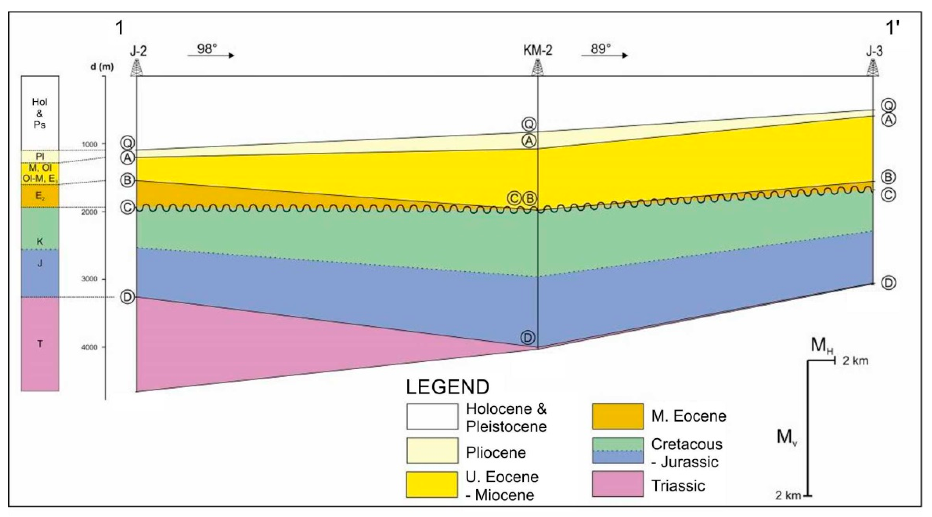
The past exploration results that were available and used in this part of the study originate from the 1971–1985 period when only few regional deep wells were drilled. These wildcat wells were not totally dry—there were gas shows in most of them and traces of heavy oil in two. With maximal depth exceeding 6000 m, this drilling campaign brought up information on the lithostratigraphy of Triassic, Jurassic, Cretaceous, Paleogene, Neogene and Quaternary sediments. Additionally, a set of correlation horizons was established then, based on the lithostratigraphy from wells and sequence boundaries observed on reflection seismics (Figure 5):
- Q—Top Pliocene;
- A—Top Miocene;
- B—Top Eocene;
- C—Top Cretaceous;
- D—Top Triassic;
- E—“Base Carbonates”, Top of Permian clastic sediments.
The transversal correlation section A–B shown in Figure 2. (for location see Figure 4) is given here as an attempt to illustrate a possible reconstruction of the subsurface geology based exclusively on the vintage deep regional wells.
The oldest E horizon delineated as the base of the carbonates was not drilled in the area of Dugi otok basin, so the thickness can only be interpreted based on the seismic data. The oldest penetrated unit is the one below the D horizon (Figure 5), composed of Triasssic dolomites and dolomitic limestones, characterized by frequent occurrence of stylolites, moldic and fenestral porosity (predominantly developed in the basal and middle part of the unit).
Jurassic and Cretaceous limestones together, build up the D–C interval. Their drilled thickness is from 900 to more than 4000 m, depending on structural position of analysed wells. The basal part of this unit is of grey to greenish dolomitic limestones with chert lenses and nodules, also with sporadic black marl intercalations. Porosity is markedly variable—from several up to even 20% based on well log interpretation [28]. The central part of this unit consists of Lower Cretaceous white limestones that have joints filled with anhydrite; limestones with stylolites; limestones with chert; and bituminous limestones and overlying dolomites. Sporadically, these sediments are characterized by increased porosities within the zones encompassing several tens of meters, interpreted to be caused by brittle tectonics. Overlying Upper Cretaceous layers are composed of dense limestones (occasionally with chert or bitumen), and bioclastic limestones (chalk), white limestones with chert and rudist limestones. Joints are not common in this unit and the existing ones are filled with organic matter—either bitumen or heavy oil, and the same goes for the stylolites. There are zones in this sub-unit where secondary porosity can be expected, but without any information about frequency and orientation of predominate joint sets. Porosities and permeabilities of Jurassic and Cretaceous limestones are strongly controlled by diagenetic and postdiagenetic processes, including dolomitization, recrystallization, dissolution, leaching, erosion and weathering. Defining the intensity and distribution of these processes in rocks would require a thorough reinterpretation of well and seismic data, which is beyond the scope of this paper.
Early to Middle Eocene limestones are the dominant lithology in the C–B interval, where basal parts of this unit also include chalk limestones and carbonate breccia. Less developed lithologies are dense laminated limestones and calcitic marls with chert nodules. Striations are observed in cores and stylolite joints as well. The youngest part of Eocene (close to B horizon) exhibits coarser carbonate bioclastics—calcarenites and calcrudites. The drilled thickness of the Eocene unit in the area is usually between 120 and 800 m, although there are wells (like Well KM-2 in Figure 5) where it is totally missing. In such cases the B horizon corresponds with the “top carbonate complex horizon”.
The composite unit of the B–A interval includes clastic and carbonate sediments of Upper Eocene, Oligocene and Miocene age. Differently subsiding tectonic blocks within the Dugi otok basin are not reflected only in orientation and size of structures, but also in changes of accommodation space. Here, the Eocene-Miocene unit is found at depths between 300 and 1330 m with a variable thickness from 100 m to more than 3000 m in the central part of this structural depression. Basal part of this interval is made of Eocene flysch-like deposits—mainly marls, marly calcarenites and limestones. They are covered by Oligocene sandstones with intercalations of calcitic marl and then by the Miocene flysch-like deposits again.
The youngest unit is comprised of deposits above A and bellow Q horizon, i.e., between the Top Miocene horizon and the seabed. That unit is composed of loose, silty-sandy sediments of Pliocene, Pleistocene and Holocene age. The depth of A horizon ranges from 300 m to over 1200 m, which at the same time gives approximately the thickness of this unit. Pliocene marls, sands and clays are distributed throughout the Dugi otok basin. Quaternary sediments are transgressive in the NE part and in conformity with Pliocene in the SW region. Transgression started in early the Pleistocene age with marine sedimentation that is still ongoing. The thickness of Quaternary sediments is also variable—from 300 m to more than 1200 m.
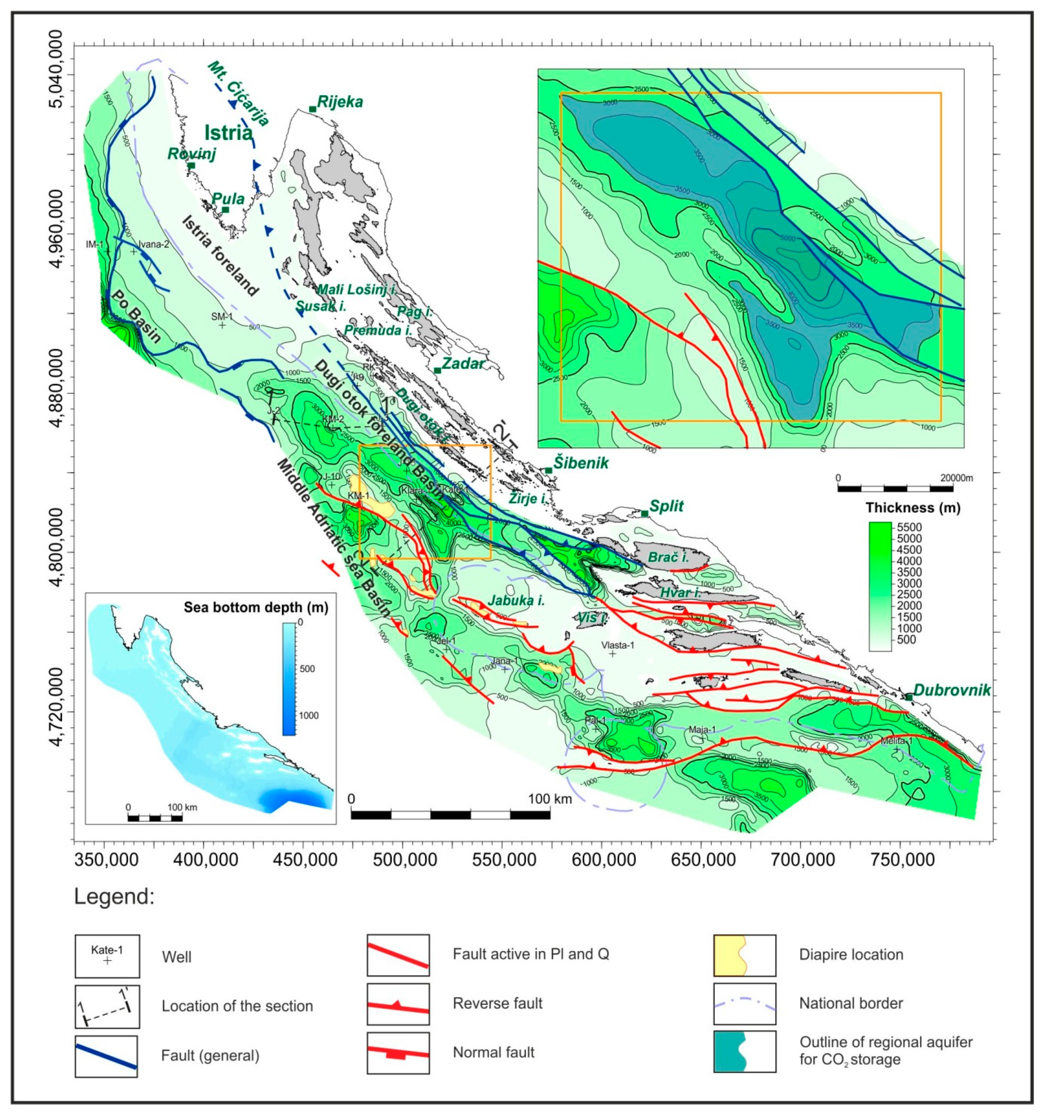
Based on the available knowledge of subsurface geology, there is potential for geological CO2 storage in the Adriatic off-shore in two regional units: Miocene sandstones (parts of the unit between A and B horizons, see Figure 5), and in the carbonate complex bounded on top by either C horizon or B horizon (Figure 5). The most important difference between these two units is in lithological compositions and porosity types. Miocene layers are a bit better explored and their depth range in combination with intergranular porosity appears to be more favourable, but they lack large structural closures. Underlying rocks of the carbonate complex have both the primary and secondary porosity (with locally increased permeability), and, in addition, there are numerous closed structures that are relatively easy to recognize on a structural contour map of the Top carbonate complex horizon (Figure 3). However, there is a lack of sufficient data to characterize and estimate areal distribution of reservoir properties in this unit.
The CO2 storage potential in these two large units must, therefore, be assessed in two different ways: Miocene sandstones are studied as a regional deep saline aquifer (DSA) named “Dugi otok”, because they were mapped within the Dugi otok basin, while within the carbonate complex, several structural uplifts were identified and referred to as structurally defined aquifers.
3.2.1. CO2 Storage Potential in the Regional Deep Saline Aquifer Dugi otok (DSA Dugi otok)
Initially formed as a foreland basin ahead of SW-propagating Dinaric thrust system, sedimentation of siliciclastic deposits in the Dugi otok basin took place during the Late Eocene, Oligocene and Miocene [25,47,48]. Miocene series is made of chalk limestones with marly and sandstone interbeds. Chalk limestones and sandstones have good reservoir properties; their porosity is in 15–25% range. Based on regional seismic interpretation (seismic facies), Miocene sediments are mostly comprised of a stacked sequence of sandstone and marl layers, with some subordinate lateral lithology variations. Lower and Middle Miocene sandstone layers are the ones where CO2 might be injected. More precisely, these are the layers and lenses of silty sandstones at depth range of 700–2100 m, regionally SW-dipping in the form of monocline unconformably covered by Pliocene marls, thus are considered as prospective for geological CO2 storage.
In Table 2, the main characteristics of DSA Dugi otok are presented together with the parameters used to calculate its theoretical CO2 storage capacity. An aquifer is treated as if it makes a consistent single large unit with average depth and porosity values and an estimated small proportion of pores that will eventually be filled with carbon dioxide once its plume spreads throughout the unit. This is an oversimplification of the effect of many processes that will eventually contribute to geological storage, in line with the so-called “conservative approach” taken in EU GeoCapacity CO2 storage atlas [7]. Outline of the aquifer is shown in Figure 4. Until a detailed exploration of Miocene units in this area is made, their presence was estimated in the region where the total thickness of Eocene to Holocene sediments exceeds 3000 m. Both the storage efficiency coefficient estimate (taken as 0.02 after [49] as P50 value for clastic regional deep saline aquifers) and the way in which the unit is mapped are major contributors to the large uncertainty in the calculation of the storage capacity. This means that the number of 327.075 Mt presented in Table 2 is just a first numerical estimate of the potential and should by no means be directly compared with the numbers given in Table 1, where the potential in depleted gas fields was estimated.
The CO2 storage capacity was calculated using the compressibility method (after [50]) and the volumetric method as described in [49]. The obtained capacities were than summed up, following the approach suggested by [51] that assumes that additional pore volume will be available for CO2 storage due to compressibility of pores and initially present pore water. If pressure increase is considered, pore compressibility should be included to storage assessment:
where: cp: pore compressibility (bar−1); δV: change in pore volume resulting from the change in pressure (m3); δp: change in pressure due to injection (bar).
cp = 1/δV × (δV/δp)
The maximum pore pressure was estimated to be 10% above the initial pore pressure, which is significantly less than what is estimated for structurally defined aquifers in carbonates. The reasoning behind this is that the initial pore pressure could not be expected to be intensively increased within the volume of the entire regional deep saline aquifer; the intensive pressure increase would be limited to volumes of the regional deep saline aquifer in the surroundings of the injection well, but overall average pore pressure should not increase as significantly, as it does for structurally defined deep saline aquifers; i.e., it should not be comparable to fracture pressure. The average porosity value was estimated from regional data on Miocene sandstones in the study area. Pore compressibility was estimated using the correlation of pore compressibility with the net confining pressure developed for Bandera sandstones [52], which have a similar initial porosity to the Miocene sandstones of DSA Dugi otok, amounting to 16.5%. The pore water compressibility was calculated after following equation [53]:
where cw is water compressibility (1/psi), Bw is water formation volume factor, p is pressure (psi), T is temperature (°F), and CNaCl is salinity of pore water (g NaCl/l).
For the salinity of pore water, the value of 35 g NaCl/l, corresponding to salinity of seawater was taken. Initial pore pressure and overburden pressure were calculated using brine density of 1025 kg/m3 and bulk wet density of overlying sediments of 2400 kg/m3. Density of CO2 was calculated based on the estimated values of pressure and temperature, using the equation of state after [46]. Average temperature was estimated using the geothermal gradient of 1.57 °C/100 m, which was calculated from data on temperature of the sea bottom [54] and the regional isothermal map of formation temperatures at the depth of 3000 m [31]. Pressure was calculated assuming the hydrostatic pressure gradient according to [10].
3.2.2. CO2 Storage Potential in Anticline Structures of the Carbonate Complex
The structural map of the Top carbonate complex horizon in the Croatian part of the Adriatic off-shore (Figure 3) was constructed based on data published in one PhD thesis [28], a Master thesis [24], two graduate theses [55,56], and that in publications in scientific and professional periodicals and proceedings [29,57,58,59]. The regional structural model is the most important here, so characteristics of structural styles and the location of km-scale structures are described first.
In terms of the predominant structural styles and structures formed in rocks of the carbonate complex and its overlying syntectonic sediments, their orientation and distribution, the three different regions in the Adriatic offshore of Croatia can be distinguished (Figure 3):
- Area to the WSW of the Premuda, Susak and Lošinj islands, together with the offshore west of Istrian peninsula. In this part of the Adriatic offshore, the top of the carbonate complex horizon gently dips in the WSW direction in a form of monocline (named the North-Adriatic monocline by [30]); in offshore Istria, it represents the gently WSW-dipping limb of the so called Istrian anticline [60,61] or the Istrian swell, sensu [30]. This wide and gentle anticline is bounded to the east-northeast by the frontal thrust of the External Dinarides exposed along the SW margin of the Ćićarija mountain (Figure 3), while its submerged WSW limb practically continues all the way underneath the submerged thrust front of the Northern Apennines (see in cross-section number 5 in [30]). Thus, the Istrian anticline represents a gently deformed foreland at first for the Dinarides fold-thrust belt during Middle to Late Eocene, and then for the Northern Apennines fold-thrust belt during Late Miocene to Quaternary. In the North-Adriatic monocline, at about 50 km offshore Rovinj where the core of the anticline crops out, a paleogeographic boundary between the AdCP and the Adriatic basin is nicely preserved. According to [30,62], this boundary is interpreted as the W-dipping Early Jurassic to Paleogene normal fault that is covered by undeformed Plio-Quaternary marls and sands, that, in addition to an absence of instrumentally recorded seismicity along this boundary, suggest that it is at present, tectonically inactive. The same is true of a set of conjugate normal faults found some 20 km east of this boundary and close to the Ivana gas-field (Figure 3).
- The area in the northern central Adriatic between the Premuda, Kornati and Žirje islands. Structurally this part of the Adriatic offshore represents presently submerged frontal part of the External Dinarides fold-thrust belt. Most, if not all, of islands in this area are fault-related anticlines formed in hangingwalls of the NE-dipping and SW verging thrust system, active during Mid-Late Eocene and Oligocene; i.e., during the main tectonic phase in the External Dinarides (see in the text above). According to interpreted reflection seismic sections available in literature (e.g., [30,62]), NE-dipping thrusts have listric geometry and sole out from two major decollement horizons: the one at approximately 5 km depth formed in Jurassic carbonates, and the other at circa 10 km depth formed in the Permo-Triassic evaporitic (salt) deposits (Figure 6). Characteristic structural styles, the morphology of reverse faults, fault-related anticlines and synclines, are nicely depicted on the transversal cross section SW of the Dugi otok island shown in Figure 6, which also shows the location of the deep well Kate-1 drilled through an anticline formed at the SW front of the Dinarides thrust system. Occasionally, NE-dipping forethrusts are associated with SW-dipping backthrusts, thus forming local pop-up structures.
- The area in the central and southern Adriatic west of Kornati islands, and the offshore Split and Dubrovnik. Structurally, this part of the Adriatic offshore is strongly affected by salt tectonics and is comprised of numerous halokinetic structures, partly in form of salt diapirs, salt walls and salt-cored anticlines of variable size and time of formation, some of them found in cores of small and large islands like Jabuka, Brusnik, Vis, Palagruža, etc. At least in part, this area corresponds with the belt of halokinetic structures know in the Italian Adriatic offshore as the Central or Mid Adriatic Ridge (e.g., [63,64]) that we presume to extend in a SE direction all the way to the offshore Dubrovnik area and even further to offshore Montenego and Albania. A part of this belt across the Jabuka island is shown in Figure 6 and interpreted by [30] as a strike-slip corridor strongly affected by salt diapirism. In case of the Jabuka island, however, Herak et al. [65] analysed a recently recorded earthquake sequence around this island and found excellent agreement between their calculated focal mechanism and the distribution of earthquake hypocentres with the NE-dipping, Jabuka-Andrija thrust fault system. Accordingly, it is included into the list of seismogenic sources of the Adriatic offshore by Kastelic et al. [66], described there as a moderately NNE-dipping seismogenic source capable of generating earthquakes with magnitudes of 5.5. Based on this data, we have partly modified a part of the cross-section, shown in Figure 6, by proposing the NE-dipping thrust fault underneath the Jabuka island, that is supposed to splay off either from the Permo-Triassic evaporite decollement, or from an even deeper decollement within the crystalline basement, as suggested by the distribution of the Jabuka earthquake sequence. The offshore area between the Vis island and Dubrovnik shows similar structural style with a prevalence of fault-related folds associated with salt tectonics. The only difference observed there is in the prevailingly E–W strike of major faults and fault-related folds that could be controlled by variable presence of evaporites. As in case of the Jabuka island, seismic activity around major structures there is instrumentally and historically well known. Actually, in addition to the catastrophic 1667 Dubrovnik earthquake (I0 = IX − X° EMS98; [67,68]), the most recent seismic activity here was recorded in an offshore area between the islands of Brač and Hvar (ML = 6.1; [69]), close to the coastline in the Ston area (ML = 6.0; [70]), and in off-shore Montenegro (MW = 7.1; [71]). Accordingly, the ongoing tectonic activity and seismicity in this area significantly reduces its potential for CO2 geological storage.
Altogether, five structural traps—potential underground CO2 storage objects, are depicted, all of them identified based on the structural map of the top of the carbonate complex. Structures are shown in detail on small maps given in Figure 3. The main characteristics of the potential storage objects are given in Table 3 and main parameters used to calculate storage capacities are given in Table 4. The average effective porosity value has been extrapolated from the laboratory measurements on core samples of the Upper Cretaceous carbonates from a single well in the northern part of the Adriatic offshore [28]. To calculate pore compressibility, the correlation of pore compressibility with net confining pressure developed for carbonate rocks has been used [72]. The correlation itself was developed in Knutson and Bohor [73]. Pore water compressibility was calculated in the same manner as for DSA Dugi otok, using a correlation by Osif [53]. The maximum pore pressure is set based on criteria 90% of 0.2 bar/m fracture gradient; i.e., as 0.18 bar/m [74,75]. In that respect, maximum increase of pore pressure was averaged to 50% from initial pore pressure, which is in accordance with value of maximum pore pressure suggested to be between 1.3 and 1.8 times the initial pore pressure [76]. Storage efficiency coefficient was taken to be 0.05, which is the product of displacement efficiencies (volumetric, EV and microscopic, ED) and net-to-gross-ratio. For product of volumetric and microscopic displacement efficiencies, the estimated value of P10 in limestone formation storage objects after Goodman et al. [49] amounting to 0.1 was taken, while for the net-to-gross ratio, representing the part of the structurally defined saline aquifer having favourable petrophysical properties needed for CO2 injection (generally corresponding to Ehn/hg after [49], the value of 0.5 was taken. The value of net-to-gross was practically based on a rule of thumb approach, since there were not enough data to make reliable geological models of these structurally defined aquifers. The porosity data used to calculate pore volume was effective porosity, but it was extrapolated from the neighbouring well, not from the wells drilled-through the structurally defined aquifers. Also, no quantitative data of permeability were available that could be used to assess net-to-gross ratio. Temperatures were estimated using geothermal gradient that was calculated from data on temperature of the sea bottom [54] and the regional isothermal map of formation temperatures at the depth of 3000 m [31]. The calculated values were in agreement with the geothermal gradient mapped by Jelić et al. [77]. Since no data on pressure were publicly available, initial pore pressure was calculated using hydrostatic pressure gradient and this can be regarded as a reasonable assumption; i.e., no overpressure is to be expected, due to the fact that drilling operations encountered problems with total mud loss when entering the carbonate complex [19]. Densities of CO2 were calculated based on the estimated values of pressure and temperature, using equation of state as defined in [46].
In this way, calculated total storage capacities in five chosen structurally defined aquifers were considerably high, which makes them valid candidates for future exploration activities. Special attention should be given to the fact that in three of five potential storage objects (structures 1, 2 and 5) CO2 is not expected to be in supercritical state, but liquid upon injection, due to low initial average temperatures that are the result of a low geothermal gradient (between 1.2 and 1.5 °C/100 m), characteristic for the studied area. This is not necessarily an issue, since according to [78], injecting CO2 in a liquid state is energetically more efficient than in supercritical state, due to its increased density, which results in lower overpressure not only at the wellhead, but also in the reservoir, because a smaller volume of fluid is displaced.
It should be emphasized that the obtained capacities are heavily burdened by the lack of data and subsequent weaknesses of the model used for their calculation and can also be treated as theoretical values only. However, it must be noted that numbers given in Table 4 are more realistic than the estimates given for the Miocene regional aquifer (Table 2), making at least some of these objects targets for future detailed exploration.
4. Discussion
Trying to estimate the storage capacity in deep saline aquifers (DSA) always disclosed a major problem, because the available data on the subsurface geology are not detailed enough. Even in the mature petroleum provinces deep aquifers were simply not drilled through in many places and there are just a few analyses of their reservoir properties. There are frequent cases where the geometry of the reservoir rock formations can be delineated based on the regional subsurface data, but other parameters—effective thickness, porosity and temperature—need to be extrapolated from the existing hydrocarbon fields in the region, if there are any. This inevitably burdens the storage capacity estimates with a lot of uncertainties. Even more so, knowing that adequate trapping conditions in parts of these regional aquifers will only later be confirmed by targeted surveys. That is why these storage estimates are regarded as theoretical capacity only (bottom of the techno-economic resource pyramid for the capacity of CO2 geological storage as defined in [79]).
There are the two significantly different types of formations where potential underground CO2 storage objects might be planned and constructed in the Adriatic offshore. Firstly, there are the thick carbonate rock formations ranging in geological age from Triassic to Eocene. On the map of top of carbonate complex (Figure 3) in the more prospective zones (i.e., far from the active faults) altogether, five structures were depicted. Three (2, 3 and 4) of them were drilled by regional wells and no hydrocarbons were discovered, meaning that they can be assessed as structurally defined aquifers. Their main characteristic is the primary and secondary porosity, thus potentially high permeability, which is indicated by total mud loss during the drilling of the mentioned wells [19]. Carbonate rock formations are, in the Adriatic offshore, covered by thick succession of clastic sediments (from Eocene to Holocene age), in which most of the rocks are impermeable, most importantly the Upper Miocene and Lower Pliocene layers. The thickness of the entire clastic basin fill is given in Figure 4. Another interesting potential storage object is the deep saline aquifer—Dugi otok (DSA Dugi otok). This is a regionally defined unit of thick Miocene succession of marls and sands that filled the Dugi otok depression. Looking at the cross-section 2–2′ in Figure 6, and given description of regional geology, this regional aquifer might be considered as an object worth the detailed exploration for two reasons—ample impermeable intervals (regional seals) of the Miocene and Pliocene age, and a regional dip SW by one largely undeformed structure, allowing plans to be made for the injection wells on the subsided SW part of the monocline and monitoring wells on the NE side. That is, should such general structure be confirmed by targeted exploration. The drawback for now is in the smaller proportion of permeable layers (estimated net pay of 0.2 is in the Table 2) and the same goes for the true reservoir properties, because they are also only regionally estimated. CO2 storage capacity declared for the DSA Dugi otok is really a preliminary estimate for two reasons—its reservoir rock properties are based only on the data from three wells, and its outline follows the contour 3000 m on the map of thickness of clastic sediments (Figure 4), because that is the area where the Miocene sediments have greatest thickness, and within this area thickness of Pleistocene and Holocene sediments is the greatest, meaning that the Miocene strata are situated in depths exceeding 1000 m. It also has to be noted that the storage efficiency factor is taken to be 0.02 [49], meaning that only such a small proportion of the estimated available pore volume might retain, once being filled with carbon dioxide (at several locations that are still to be found). This storage capacity in aquifers might be prepared for use only after the deliberated exploration of these objects, not only to fully investigate their reservoir properties, but also to confirm the integrity of their cap rocks. The third option, storage objects in the three gas fields might easily be prepared for pilot injections and have upscaling potential, but this will become available only once their reservoirs are depleted and hydrocarbon exploitation licences are expired or terminated.
5. Conclusions
It is important for the Republic of Croatia to consider the possibilities of reducing their emissions by making use of CCS technology. This is the only way to achieve the Paris agreement targets in time, simply because the existing large stationary industrial sources from the energy and other industrial sectors can be cost-effectively, safely and quickly decarbonised, before the uptake of renewable technologies really starts “kicking in.” Timely preparation of this will positively influence energy prices and save many jobs, not to mention that every nation should take care of its contribution to the global effort to reduce GHG emissions. Croatia is at present, still far from phasing out its fossil fuel energy sources and has a comparably high proportion of industrial emissions that will not just disappear in the near future. This can all be dealt with by evaluating the new “geological storage resource” to make use of the deep subsurface rock formations by the building of carbon capture and storage (CCS) systems.
There are favourable conditions for geological storage of CO2 in Croatia, both in the southern part of the Pannonian basin and the Adriatic offshore [7]. The capacity declared for hydrocarbon fields is better defined than estimates for aquifer formations which still need detailed exploration in order to define the structures for storage. Regarding the Adriatic offshore, it is far less explored than Pannonian Basin, but it has a considerable dataset, enough for screening in terms of the basic characteristics of subsurface geology.
Since almost half of emissions occur in the coastal areas, the Adriatic offshore’s CO2 storage potential gains importance now that even exceeds petroleum exploration. That is simply because one can import oil or natural gas, but one cannot export CO2. There is still the significant professional knowledge and technical potential from the otherwise declining upstream part of national petroleum industry. It simply must be put into use while the window of opportunity still exists.
The most prospective CO2 storage objects are the small gas fields in the Northern Adriatic. Total storage potential in their reservoirs is not large (32 Mt) but it is available, and there are installations on exploitation sites which would significantly reduce investments. Another group of objects are deep saline aquifers. They offer much larger potential but with large uncertainty; that is why this is called “theoretical storage capacity”. We think we have demonstrated the two most important “CO2 storage plays” based on the regional geological data—Miocene sandstones in the Dugi otok basin (as a regional deep saline aquifer, DSA Dugi otok) and Triassic to Eocene carbonate rock formations, whose paleotopography is covered by thick impermeable layers of Miocene to Early Pliocene age, so five structurally defined aquifers were delineated, each of them representing a site where CO2 storage capacity could be investigated on a local scale. They are all distant from sources of carbon dioxide and maybe the two of them will eventually prove to be too small to be economical, but the other three show significant potential that should not be overlooked.
Author Contributions
Conceptualization, B.S. and I.K.M.; methodology, B.S., I.K.M., M.C. and D.V.; software, I.K.M., M.C. and D.V.; validation of regional geology, J.V. and B.T.; formal analysis, I.K.M. and D.V.; investigation, B.S., I.K.M. and M.C.; resources, B.S. and M.C.; data curation, I.K.M. and M.C.; writing—original draft preparation, B.S., I.K.M. and M.C.; writing—review and editing, J.V. and B.T.; visualization, I.K.M. and M.C.; supervision, B.S.; project administration, B.S. and M.C.; funding acquisition, B.S.
Funding
The publication process was supported by the Development Fund of the Faculty of Mining, Geology and Petroleum Engineering, University of Zagreb. The authors would like to acknowledge that they have had support from European Commission (in a number of FP6, FP7 and Horizon 2020 projects), from the Croatian Environmental Protection and an Energy Efficiency Fund, from HEP (Croatian power utility who once ordered a professional study) and from the University of Zagreb with which they are affiliated.
Conflicts of Interest
The authors declare no conflict of interest.
References
- Markušić, S.; Herak, M. Seismic zoning of Croatia. Nat. Hazards 1999, 18, 269–285. [Google Scholar] [CrossRef]
- Herak, M.; Živčić, M.; Sović, I.; Cecić, I.; Dasović, I.; Stipčević, J.; Herak, D. Historical Seismicity of the Rijeka Region (Northwest External Dinarides, Croatia)—Part II: The Klana Earthquakes of 1870. Seismol. Res. Lett. 2018, 89, 1524–1536. [Google Scholar]
- HAOP Croatian Environmental Pollution Register. Available online: http://roo-preglednik.azo.hr/Default.aspx (accessed on 7 June 2019).
- Plinacro Ltd—Gas Transport System Operator. Available online: http://www.plinacro.hr/default.aspx?id=162 (accessed on 26 August 2019).
- Hercecg, H.; Krpan, H. Optimizacija sustava dehidracije plina na platformi Ivana K. Gas dehydration optimization in the Ivana K platform. Naft. Plin 2019, 39, 84–94. [Google Scholar]
- Herak, M. Karta Potresnih Područja. Available online: http://seizkarta.gfz.hr/karta.php (accessed on 25 August 2019).
- Vangkilde-Pedersen, T.; Anthonsen, K.L.; Smith, N.; Kirk, K.; Neele, F.; van der Meer, B.; Le Gallo, Y.; Bossie-Codreanu, D.; Wojcicki, A.; Le Nindre, Y.-M.; et al. Assessing European capacity for geological storage of carbon dioxide–the EU GeoCapacity project. Energy Proced. 2009, 1, 2663–2670. [Google Scholar] [CrossRef]
- Poulsen, N.; Holloway, S.; Neele, F.; Smith, N.A.; Kirk, K. Assessment of CO2 Storage Potential in Europe. European Commission Contract No ENER/C1/154-2011-SI2.611598. CO2StoP Final Report. 2014. Available online: http://energyx.com.au/files/56-2014%20Final%20report.pdf (accessed on 31 July 2019).
- Cota, L.; Dalić, N.; Šikonja, Ž. INA’s Experience in Hydrocarbon Exploration in Croatia. Nafta 2014, 65, 142–146. [Google Scholar]
- Malvić, T.; Đureković, M.; Čogelja, Z.; Šikonja, Ž.; Ilijaš, T.; Kruljac, I. Exploration and production activities in northern Adriatic Sea (Croatia), successful joint venture INA (Croatia) and ENI (Italy). Nafta 2011, 62, 287–292. [Google Scholar]
- Đureković, M.; Krpan, M.; Pontiggia, M.; Ruvo, L.; Savino, R.; Volpi, B. Geological modelling and petrophysical characterisation of turbiditic reservoirs of the Ivana gas field-R. Croatia. Nafta 1998, 49, 241–258. [Google Scholar]
- Đureković, M.; Jovović, S.; Krpan, M.; Jelić-Balta, J. Ika gas field characterization and modeling. Nafta 2002, 53, 273–282. [Google Scholar]
- Marić Đureković, Ž. Litofacijesne i stratigrafske značajke pleistocenskih naslaga podmorja sjevernoga Jadrana na temelju visokorazlučivih karotažnih mjerenja. In Lithofacies and Stratigraphy of Pleistocene Deposits in North Adriatic Offshore by Using High-Resolution Well Logs; University of Zagreb: Zagreb, Croatia, 2011. [Google Scholar]
- Zelić, M.; Mlinarić, Ž.; Jelić-Balta, J. Croatian Northern Adriatic Ivana gas field ready for development (Reservoir characteristics and gas inflow conditions into the well). Nafta 1999, 50, 19–37. [Google Scholar]
- Velić, J.; Malvić, T.; Cvetković, M.; Velić, I. Stratigraphy and petroleum geology of the Croatian part of the Adriatic basin. J. Pet. Geol. 2015, 38, 281–300. [Google Scholar] [CrossRef]
- Busetti, M.; Volpi, V.; Barison, E.; Giustiniani, M.; Marchi, M.; Ramella, R.; Wardell, N.; Zanolla, C. Meso-Cenozoic seismic stratigraphy and the tectonic setting of the Gulf of Trieste (northern Adriatic). GeoActa 2010, 3, 1–14. [Google Scholar]
- Grandić, S.; Krakatović, I.; Rusan, I. Hydrocarbon potential assesment of the slope deposits along the SW Dinarides carbonate platform edge. Nafta 2010, 61, 325–338. [Google Scholar]
- Tišljar, J. Origin and Depositional Environments of the Evaporite and Carbonate Complex (Upper Permian) from the Central Part of the Dinarides (Southern Croatia and Western Bosnia). Geol. Croat. 1992, 45, 116–126. [Google Scholar]
- Spaić, V. Oil and gas bearingness and structural elements of Adriatic islands and peninsulas (Outer Dinarides) with special review of anhydrite—Carbonate Mesozoic complex and diapiric belt. Nafta 2012, 63, 29–37. [Google Scholar]
- Bahun, S. Geološki odnosi okolice Donjeg Pazarisšta u Lici (trijas i tercijarne Jelar naslage). Geological relations of the surroundings of Donje Pazarište in Lika, Croatia. Geološki Vjesn. 1963, 16, 161–170. [Google Scholar]
- Pamić, J. Triassic magmatism of the Dinarides in Yugoslavia. Tectonophysics 1984, 109, 273–307. [Google Scholar] [CrossRef]
- Vlahović, I.; Tišljar, J.; Velić, I.; Matičec, D. Evolution of the Adriatic Carbonate Platform: Palaeogeography, main events and depositional dynamics. Palaeogeogr. Palaeoclimatol. Palaeoecol. 2005, 220, 333–360. [Google Scholar] [CrossRef]
- Smirčić, D.; Kolar-Jurkovšek, T.; Aljinović, D.; Barudžija, U.; Jurkovšek, B.; Hrvatović, H. Stratigraphic Definition and Correlation of Middle Triassic Volcaniclastic Facies in the External Dinarides: Croatia and Bosnia and Herzegovina. J. Earth Sci. 2018, 29, 864–878. [Google Scholar]
- Babić, K. Tektonska Kretanja i Solne Strukture u Području Vis-Biševo-Sušac. Tectonic Momvements and Salt Structures in Vis-Biševo-Sušac Area. Master’s Thesis, University of Zagreb, Zagreb, Croatia, 1990. [Google Scholar]
- Scisciani, V.; Esestime, P. The Triassic Evaporites in the Evolution of the Adriatic Basin. In Permo-Triassic Salt Provinces of Europe, North Africa and the Atlantic Margins; Soto, J.I., Flinch, J., Tari, G., Eds.; Elsevier: Amsterdam, The Netherlands, 2017; pp. 499–516. [Google Scholar]
- Prelogović, E.; Kranjec, V. Geological development of the Adriatic area (Geološki razvitak područja Jadranskog mora—In Croatian). Pomor. Zb. 1983, 21, 387–405. [Google Scholar]
- Veseli, V.; Tišljar, J.; Tadej, J.; Premec-Fuček, V. Lithofacies and Biofacies of the Cretaceous and Paleogene Carbonate Sediments in Kate-1 offshore well (Kornati Area, Croatia, Adriatic Sea). In Proceedings of the second International Symposium on the Adriatic Carbonate Platform, Zagreb, Croatia, 12–18 May 1991; p. 115. [Google Scholar]
- Veseli, V. Facijesi karbonatnih sedimenata mlađeg mezozoika i paleogena u pučinskim bušotinama Sjevernoga Jadrana. Late Mesosoic and Paleogene Carbonate Facies in the off-Shore Wells in the Northen Adria; University of Zagreb: Zagreb, Croatia, 1999. [Google Scholar]
- Grandić, S.; Veseli, V. Hydrocarbon potential of Dugi Otok basin in offshore Croatia. Nafta 2002, 53, 215–224. [Google Scholar]
- Fantoni, R.; Franciosi, R. Mesozoic extension and Cenozoic compression in Po Plain and Adriatic foreland. Rend. Online Soc. Geol. Ital. 2010, 9, 181–196. [Google Scholar]
- Kolbah, S.; Grandić, S. New Commercial Oil Discovery at Rovesti Structure in South Adriatic and its Importance for Croatian Part of Adriatic Basin. Nafta 2009, 60, 68–82. [Google Scholar]
- Cazzini, F.; Zotto, O.D.; Fantoni, R.; Ghielmi, M.; Ronchi, P.; Scotti, P. Oil and gas in the adriatic foreland, Italy. J. Pet. Geol. 2015, 38, 255–279. [Google Scholar] [CrossRef]
- Wrigley, R.; Hodgson, N.; Esestime, P. Petroleum geology and hydrocarbon potential of the adriatic basin, offshore Croatia. J. Pet. Geol. 2015, 38, 301–316. [Google Scholar] [CrossRef]
- Grandić, S.; Boromisa-Balaš, E.; Šušterić, M. Exploration concept and characteristics of the stratigraphic and structural models of the Dinarides in Croatian offshore area PART II. Hydrocarbon Consideration. Nafta 1997, 48, 249–266. [Google Scholar]
- Korbar, T. Orogenic evolution of the External Dinarides in the NE Adriatic region: A model constrained by tectonostratigraphy of Upper Cretaceous to Paleogene carbonates. Earth-Sci. Rev. 2009, 96, 296–312. [Google Scholar] [CrossRef]
- Babić, L.; Zupanič, J. Laterally variable development of a basin-wide transgressive unit of the North Dalmatian Foreland Basin (Eocene, Dinarides, Croatia). Geol. Croat. 2012, 65, 1–27. [Google Scholar] [CrossRef]
- Mrinjek, E.; Nemec, W.; Pecinger, V.; Mikša, G.; Vlahović, I.; Ćosović, V.; Velić, I.; Bergant, S.; Matičec, D. The Eocene-Oligocene Promina Beds of the Dinaric Foreland Basin in Northern Dalmatia. J. Alp. Geol. 2012, 55, 409–451. [Google Scholar]
- Jiménez-Moreno, G.; de Leeuw, A.; Mandic, O.; Harzhauser, M.; Pavelić, D.; Krijgsman, W.; Vranjković, A. Integrated stratigraphy of the Early Miocene lacustrine deposits of Pag Island (SW Croatia): Palaeovegetation and environmental changes in the Dinaride Lake System. Palaeogeogr. Palaeoclimatol. Palaeoecol. 2009, 280, 193–206. [Google Scholar] [CrossRef]
- De Leeuw, A.; Mandic, O.; Vranjković, A.; Pavelić, D.; Harzhauser, M.; Krijgsman, W.; Kuiper, K.F. Chronology and integrated stratigraphy of the Miocene Sinj Basin (Dinaride Lake System, Croatia). Palaeogeogr. Palaeoclimatol. Palaeoecol. 2010, 292, 155–167. [Google Scholar] [CrossRef]
- Amadori, C.; Garcia-Castellanos, D.; Toscani, G.; Sternai, P.; Fantoni, R.; Ghielmi, M.; Di Giulio, A. Restored topography of the Po Plain-Northern Adriatic region during the Messinian base-Level drop—Implications for the physiography and compartmentalization of the palaeo-Mediterranean basin. Basin Res. 2018, 30, 1247–1263. [Google Scholar] [CrossRef]
- Ghielmi, M.; Minervini, M.; Nini, C.; Rogledi, S.; Rossi, M. Late Miocene-Middle Pleistocene sequences in the Po Plain—Northern Adriatic Sea (Italy): The stratigraphic record of modification phases affecting a complex foreland basin. Mar. Pet. Geol. 2013, 42, 50–81. [Google Scholar] [CrossRef]
- EMODnet Bathimetry—Understanding the Topography of the European Seas. Available online: https://portal.emodnet-bathymetry.eu/help/help.html (accessed on 2 June 2019).
- McCabe, P.J. Energy resources—Cornucopia or empty barrel? Am. Assoc. Pet. Geol. Bull. 1998, 82, 2110–2134. [Google Scholar]
- Velić, J. Geologija nafte Petroleum Geology; University of Zagreb: Zagreb, Croatia, 2007. [Google Scholar]
- Živković, V. Proizvodne platforme eksploatacijskog polja Sjeverni Jadran. In Production Platforms of Exploitation Field North Adriatic; University of Zagreb: Zagreb, Croatia, 2015. [Google Scholar]
- Span, R.; Wagner, W. A new equation of state for carbon dioxide covering the fluid region from the triple-Point temperature to 1100 K at pressures up to 800 MPa. J. Phys. Chem. Ref. Data 1996, 25, 1509–1596. [Google Scholar] [CrossRef]
- Pavlovec, R.; Drobne, K.; Sikic, L. Upper Eocene and Oligocene in Yugoslavia. In Developments in Palaeontology and Stratigraphy; Pomerol, C., Premoli-Silva, I., Eds.; Elsevier: Amsterdam, The Netherlands, 1986; pp. 109–111. [Google Scholar]
- Frixa, A.; Gorla, L.; Liverani, G.; Nini, C.; Parlov, B.; Pompadoro, G. Eocene-Miocene Calcareous Turbiditic Play in a Dinaric Foredeep: The Dugi Otok Basin, Offshore Croatia; AAPG: Barcelona, Spain, 2003; pp. 21–24. [Google Scholar]
- Goodman, A.; Hakala, A.; Bromhal, G.; Deel, D.; Rodosta, T.; Frailey, S.; Small, M.; Allen, D.; Romanov, V.; Fazio, J.; et al. U.S. DOE methodology for the development of geologic storage potential for carbon dioxide at the national and regional scale. Int. J. Greenh. Gas Control 2011, 5, 952–965. [Google Scholar] [CrossRef]
- van der Meer, L.; Egberts, P.J.P. A General Method for Subsurface CO2 Storage Capacity Calculations. In Proceedings of the Offshore Technology Conference, Huston, TX, USA, 5–8 May 2008; pp. 889–895. [Google Scholar]
- Vulin, D.; Kurevija, T.; Kolenkovic, I. The effect of mechanical rock properties on CO2 storage capacity. Energy 2012, 45, 512–518. [Google Scholar] [CrossRef]
- Zimmerman, R.W. Chapter 8. Tubular Pores Part Two: Compressibility and Pore Structure; Elsevier Science: Amsterdam, The Netherlands, 1991. [Google Scholar]
- Osif, T.L. The Effects of Salt, Gas, Temperature, and Pressure on the Compressibility of Water. SPE Reserv. Eng. 1988, 3, 175–181. [Google Scholar] [CrossRef]
- Russo, A.; Carniel, S.; Sclavo, M.; Krzelj, M. Climatology of the Northern-Central Adriatic Sea. In Modern Climatology; Wang, S., Gillies, R., Eds.; IntechOpen: Rijeka, Croatia, 2012; pp. 177–212. [Google Scholar]
- Bakić, H. Strukturne značajke Jadranskog podmorja jugozapadno od Istarskog poluotoka. Structural features of Adriatic offshore Southeast of Istira Peninsula. Master’s Thesis, University of Zagreb, Zagreb, Croatia, 2007. [Google Scholar]
- Križanić, D. Strukturno-Stratigrafski odnosi i “bright-spot” anomalije u ležištima sjeverno od polja Ivana. In Structural-Strtigraphic Relations and Bright Spor Anomalies North of IVANA Gas Field; University of Zagreb: Zagreb, Croatia, 1999. [Google Scholar]
- Grandić, S.; Boromisa-Balaš, E.; Šušterić, M.; Kolbah, S. Hydrocarbon possibilites in the Eastern offshore Adriatic Slope zone of Croatian area. Nafta 1999, 50, 51–73. [Google Scholar]
- Prelogović, E.; Pribičević, B.; Ivković, Ž.; Dragičević, I.; Buljan, R.; Tomljenovic, B. Recent structural fabric of the Dinarides and tectonically active zones important for petroleum-Geological exploration. Nafta 2004, 55, 155–161. [Google Scholar]
- Tomljenovic, B.; Herak, M.; Kralj, K.; Prelogović, E.; Bostjančić, I.; Matoš, B. Active tectonics, sismicity and seismogenic sources of the Adriatic coastal and offshore region of Croatia. In Proceedings of the Riassunti Estesi delle Comunicazioni, Trieste, Italy, 16–19 November 2009; pp. 133–136. [Google Scholar]
- Marinčić, S.; Matičec, D. Tektonika i kinematika deformacija na primjeru Istre [Tectonics and kinematics of deformations, an Istrian Model]. Geološki Vjesn. 1991, 44, 257–268. [Google Scholar]
- Matičec, D. Neotectonic deformations in western Istria, Croatia. Geol. Croat. 1994, 47, 199–204. [Google Scholar]
- Grandić, S. Periplatform clastics of Croatian offshore and their petroleum geological significance. Nafta 2009, 60, 503–511. [Google Scholar]
- Geletti, R.; Del Ben, A.; Busetti, M.; Ramella, R.; Volpi, V. Gas seeps linked to salt structures in the central adriatic sea. Basin Res. 2008, 20, 473–487. [Google Scholar] [CrossRef]
- Casero, P.; Bigi, S. Structural setting of the Adriatic basin and the main related petroleum exploration plays. Mar. Pet. Geol. 2013, 42, 135–147. [Google Scholar] [CrossRef]
- Herak, D.; Herak, M.; Prelogović, E.; Markušić, S.; Markulin, Ž. Jabuka island (Central Adriatic Sea) earthquakes of 2003. Tectonophysics 2005, 398, 167–180. [Google Scholar] [CrossRef]
- Kastelic, V.; Vannoli, P.; Burrato, P.; Fracassi, U.; Tiberti, M.M.; Velensise, G. Seismogenic sources in the Adriatic Domain. Mar. Pet. Geol. 2013, 42, 191–213. [Google Scholar] [CrossRef] [Green Version]
- Herak, D.; Herak, M.; Brkić, I. Great tremor, sismicity and seismic hazard of wider Dubrovnik area [Velika trešnja, seizmičnost i potresna opasnost na širem Dubrovačkom području]. Dubrov. Čas. Književ. Znan. 2017, 28, 5–18. [Google Scholar]
- Albini, P. The great 1667 Dalmatia Earthquake: An in-Depth Case Studdy; Springer: New York, NY, USA, 2015. [Google Scholar]
- Herak, M.; Orlić, M.; Kunovec-Varga, M. Did the Makarska earthquake of 1962 generate a tsunami in the central Adriatic archipelago? J. Geodyn. 2001, 31, 71–86. [Google Scholar] [CrossRef]
- Markušić, S.; Herak, D.; Ivančić, I.; Sović, I.; Herak, M.; Prelogović, E. Seismicity of Croatia in the period 1993-1996 and the Ston-Slano earthquake of 1996. Geofizika 1998, 15, 83–102. [Google Scholar]
- Benetatos, C.; Kiratzi, A. Finite-fault slip models for the 15 April 1979 (Mw 7.1) Montenegro earthquake and its strongest aftershock of 24 May 1979 (Mw 6.2). Tectonophysics 2006, 421, 129–143. [Google Scholar] [CrossRef]
- Chilingarian, G.V.; Torabazdeh, J.; Robertson, J.O.; Rieke, H.H.; Mazzullo, S.J. Carbonate Reservoir Characterization: A Geologic-Engineering Analysis. In Developments in Petroleum Science; Chilingarian, G.V., Mazzullo, S.J., Rieke, H.H., Eds.; Elsevier: Amsterdam, The Netherlands, 1992. [Google Scholar]
- Knutson, C.F.; Bohor, B.F. Reservoir rock behavior under moderate confining pressure. In Rock Mechanics; Fairhurst, C., Ed.; Pergamon: New York, NY, USA, 1963; pp. 627–658. [Google Scholar]
- Pooladi-Darvish, M.; Moghdam, S.; Xu, D. Multiwell injectivity for storage of CO2 in aquifers. Energy Procedia 2011, 4, 4252–4259. [Google Scholar] [CrossRef]
- Griffith, C.A. Physical Characteristics of Caprock Formations used for Geological Storage of CO2 and the Impact of Uncertainty in Fracture Properties in CO2 Transport through Fractured Caprocks; Carnegie Mellon University: Pittsburgh, PA, USA, 2012. [Google Scholar]
- Zhou, Q.; Birkholzer, J.T.; Tsang, C.F.; Rutqvist, J. A method for quick assessment of CO2 storage capacity in closed and semi-Closed saline formations. Int. J. Greenh. Gas Control 2008, 2, 626–639. [Google Scholar] [CrossRef]
- Jelić, K.; Kevrić, I.; Krasić, O. Temperatura i toplinski tok u tlu Hrvatske [Temperature and heat flow in the soil of Croatia]. In Proceedings of the First Croatian Geological Congress, Opatija, Croatia, 18–21 October 1995; pp. 245–249. [Google Scholar]
- Vilarrasa, V.; Silva, O.; Carrera, J.; Olivella, S. Liquid CO2 injection for geological storage in deep saline aquifers. Int. J. Greenh. Gas Control 2013, 14, 84–96. [Google Scholar] [CrossRef]
- Bradshaw, J.; Bachu, S.; Bonijoly, D.; Burruss, R.; Holloway, S.; Christensen, N.P.; Mathiassen, O.M. CO2 storage capacity estimation: Issues and development of standards. Int. J. Greenh. Gas Control 2007, 1, 62–68. [Google Scholar] [CrossRef]
Figure 1.
Location map of large stationary CO2 sources (Croatian Environmental Pollution Register [3]), main pipeline network (after [4,5]), contours of the potential CO2 geological storage objects in the Adriatic offshore and the peak ground acceleration values with a return period of 475 years (after [6]).

Figure 2.
Schematic cross-section A–B of the Adriatic offshore (NW–SE, modified after [26,27,28,29]; locations in Figure 4).

Figure 3.
Structural map of the Top of carbonate complex with marked locations of potential storage objects within five structural traps. Map compiled after [25,28,30,31,32,33].

Figure 4.
Thickness of an Eocene to Holocene sequence of clastic sediments with the regional, deep saline aquifer outlined as a potential CO2 storage object. Thickness is derived based on depth of the top of the carbonate complex (Figure 3) and sea bottom depth [42].


Figure 6.
Transversal cross-section 2–2′ through the deep well Kate-1, south of the Dugi otok island (after [30]; stratigraphy modified after [15]). Vertical exaggeration is 2:1. Fault planes are marked with black lines. Location in Figure 3 and Figure 4.


Table 1.
Summary of parameters used for CO2 storage capacity estimation of the Northern Adriatic gas-fields.
Table 1.
Summary of parameters used for CO2 storage capacity estimation of the Northern Adriatic gas-fields.
| Field Name | Stratigraphic Unit | Lithology | Depth (m) | Proven Total Recoverable Gas | Bg | CO2 Density (t/m3) | Estimated CO2 Storage Capacity (Mt) |
|---|---|---|---|---|---|---|---|
| Ida | Pliocene-Pleistocene | sandstone | 870 | 2.407 | 0.0051 | 0.3812 | 10.502 |
| Ika | Pliocene-Pleistocene | sandstone/carbonates | 1300 | 2.520 | 0.0045 | 0.5977 | 11.903 |
| Marica | Pliocene-Pleistocene | sandstone | 1010 | 1.816 | 0.0038 | 0.5396 | 9.707 |
| Total estimated CO2 storage capacity (Mt) | 32.112 | ||||||
Table 2.
Characteristics of the regional deep saline aquifer Dugi otok.
| Potential Storage Object | Average Depth (m) | Net-to-Gross | Average Porosity (%) | Pore Volume (m3) | Initial Pore Pressure (bar) | Initial Temp. (°C) |
|---|---|---|---|---|---|---|
| DSA Dugi otok | 2923.5 | 0.2 | 15 | 16.7579 × 10⁹ | 293.97 | 57.01 |
| Pore pressure increase (%) | Pore compressibility (bar−1) | Pore water compressibility (bar−1) | CO2 density at maximum pore pressure (kg/m3) | Storage efficiency coefficient (-) | Total CO2 storage capacity (Mt) | |
| 10 | 3.5 × 10⁻⁵ | 5.87 × 10⁻⁵ | 857.75 | 0.02 | 327.075 |
Table 3.
Main characteristics of structurally defined aquifers in carbonates.
| Potential Storage Object | Top Depth (m) | Average Depth (m) | Average Sea Depth (m) | Average Porosity (%) | Pore Volume (106 m3) | Average Initial Pore Pressure (bar) | Average Temperature (°C) |
|---|---|---|---|---|---|---|---|
| Structure 1 | 891 | 945.5 | 65 | 18.85 | 209.64 | 95.1 | 26.99 |
| Structure 2 | 843 | 921.5 | 65 | 18.85 | 467.14 | 92.7 | 26.61 |
| Structure 3 | 1670 | 2085 | 113 | 18.85 | 4473.84 | 209.7 | 43.96 |
| Structure 4 | 1772 | 2136 | 133 | 18.85 | 2066.99 | 214.8 | 44.45 |
| Structure 5 | 780 | 890 | 121 | 18.85 | 778.51 | 89.5 | 23.23 |
Table 4.
Storage capacity estimation using compressibility method for structurally defined aquifers in carbonates.
Table 4.
Storage capacity estimation using compressibility method for structurally defined aquifers in carbonates.
| Potential Storage Object | Storage Efficiency Coefficient (-) | Pore Pressure Increase (%) | Pore Compressibility (bar−1) | Water Compressibility (10−5 bar−1) | CO2 Density * (kg/m3) | Total Storage Capacity (Mt) |
|---|---|---|---|---|---|---|
| Structure 1 | 0.05 | 50 | 10.15 × 10⁻⁵ | 5.55 × 10⁻⁵ | 857.68 | 8.99 |
| Structure 2 | 0.05 | 50 | 10.15 × 10⁻⁵ | 5.54 × 10⁻⁵ | 856.27 | 20.00 |
| Structure 3 | 0.05 | 50 | 6.96 × 10⁻⁵ | 5.73 × 10⁻⁵ | 902.58 | 201.90 |
| Structure 4 | 0.05 | 50 | 6.96 × 10⁻⁵ | 5.74 × 10⁻⁵ | 904.89 | 93.52 |
| Structure 5 | 0.05 | 50 | 11.17 × 10⁻⁵ | 5.51 × 10⁻⁵ | 872.18 | 33.95 |
* CO2 density at maximum pore pressure (sum of average initial pore pressure and overpressure caused by injection).
© 2019 by the authors. Licensee MDPI, Basel, Switzerland. This article is an open access article distributed under the terms and conditions of the Creative Commons Attribution (CC BY) license (http://creativecommons.org/licenses/by/4.0/).
Share and Cite
MDPI and ACS Style
Saftić, B.; Kolenković Močilac, I.; Cvetković, M.; Vulin, D.; Velić, J.; Tomljenović, B. Potential for the Geological Storage of CO2 in the Croatian Part of the Adriatic Offshore. Minerals 2019, 9, 577. https://doi.org/10.3390/min9100577
AMA Style
Saftić B, Kolenković Močilac I, Cvetković M, Vulin D, Velić J, Tomljenović B. Potential for the Geological Storage of CO2 in the Croatian Part of the Adriatic Offshore. Minerals. 2019; 9(10):577. https://doi.org/10.3390/min9100577
Chicago/Turabian StyleSaftić, Bruno, Iva Kolenković Močilac, Marko Cvetković, Domagoj Vulin, Josipa Velić, and Bruno Tomljenović. 2019. "Potential for the Geological Storage of CO2 in the Croatian Part of the Adriatic Offshore" Minerals 9, no. 10: 577. https://doi.org/10.3390/min9100577
Note that from the first issue of 2016, this journal uses article numbers instead of page numbers. See further details here.