Article

Research on Heat Transfer through a Double-Walled Heat Shield of a Firefighting Robot

by
Amado Ștefan
1,
Lucian Ștefăniță Grigore
1,
Cristian Molder
1,
Ionica Oncioiu
2,*,
Bogdan Vlădescu
1,
Daniel Constantin
1,
Damian Gorgoteanu
1,
Răzvan-Ionuț Bălașa
1 and
Ștefan Mustață
1
1
Center of Excellence in Robotics and Autonomous Systems—CERAS, Military Technical Academy “FERDINAND I”, 39-49 George Coșbuc Av., 050141 Bucharest, Romania
2
Faculty of Economics, Titu Maiorescu University, 040051 Bucharest, Romania
*
Author to whom correspondence should be addressed.
Machines 2022, 10(10), 942; https://doi.org/10.3390/machines10100942
Submission received: 23 August 2022 / Revised: 13 October 2022 / Accepted: 14 October 2022 / Published: 17 October 2022
(This article belongs to the Special Issue Heterogeneity in Intelligent Mobile Robots and Systems)

Abstract

:
Burning forests, petrochemical installations and material warehouses generate very large fields and thermal gradients, which means human intervention to extinguish the fire is greatly limited. For that reason, the use of robots is recommended, but because of high temperature, they have to be equipped with protective thermal shields. This article is an analytical, numerical, and experimental study on how a double-wall, stainless steel heat shield influenced the thermal gradients acting on a firefighting robot. Following the analytical analysis at a maximum temperature of 350 °C, it was possible to identify the parameters that must be measured to be correlated with those from finite element analysis (FEM) analysis. Experimental tests showed a decrease in temperature behind the shield due to the stainless steel and the double-walled. The main conclusions and contributions of this paper consist of the realization of a finite difference model with FEM that takes into account conduction, convection, and radiation. It also highlights the benefits of using a multilayer shield.

1. Introduction

Robotic risk response systems are very useful [1,2,3] for protecting personnel and increasing efficiency [4,5,6]. However, it is advisable that robotic firefighting systems be equipped with protective equipment against radiation [7,8] and high temperatures [9] because a firefighting robot might pass through areas contaminated by radiation or chemicals. Excessive sensor equipment is not the best solution, so additional risk area investigation systems are used where a robot must intervene [10,11,12,13].
The design and Implementation of highly complex and robust robotic intervention systems lead to prohibitive costs. In this case, a low-cost solution needs to be devised so that materials are used efficiently [14,15].
Increasing the intervention capacity of a fire-extinguishing robot can be achieved by attaching a thermal protection shield. If it can be attached quickly, the preparation time will be short. The setup is very easy and the robot must intervene before the fire department does. Because there is no mention in the literature of the use of specialized programs and methods to evaluate autonomous mobile robots in extreme environments with high temperatures, a 6 × 6 vehicle model was used for which there are experimental data capable of validating the simulation methods. The data concerned the environmental operating conditions, overall dimensions, and ability to tolerate certain components (such as a heat shield) that may alter the center of gravity. When temperatures are high and the wind changes direction, it makes these often contradictory needs even harder to meet.
The purpose of this paper is to show that a double-wall heat shield reduces the temperature to which a firefighting robot is subjected during a mission. Achieving this goal consisted of creating the heat shield, making a laboratory stand to test the shield, making an analytical calculation model, and performing modeling/simulation in finite element analysis (FEM).
Because the objectives for effective intervention and robot protection are antagonistic to one another [16,17], it was thought that a workable compromise might be expressed as follows:
  • Conditions imposed by engine type:
    Thermal management [18];
    Payload [19,20];
    Dynamism characteristics depending on terrain and artificial obstacles [21,22,23];
  • Limitations resulting from the degree of fire evolution prediction [24,25];
  • Limitations resulting from the degree of thermal gradients of heat sources [26,27];
  • Material properties specific to the robot structure, as well as the components intended to protect the robot and the equipment from high temperatures (sensors, accumulators, and controllers) [28,29,30].
For the robot, stainless steel was used for the magnetic protection systems as it was found that the reflection index of this type of stainless steel was higher; therefore, the temperature reduction gradient on the surface of the shield could be increased. The choice of material was made by testing the different types available, and the values for the one used [28] were entered into the calculations.
The fire extinguishing robot was developed at the level of an experimental laboratory model.
Formulating the task from the point of view of our own research refers to:
  • The possibility of flaws in the design/realization of the robot, as these will be at technology readiness level 2 (TRL2) in the research center laboratory;
  • The lack of specialized laboratory equipment for the mechanical processing of high-temperature-resistant materials;
  • Determining the geometric shape of the protection system to obtain coefficients of refraction and reflection corresponding to a reduction in the amount of thermal energy to the robot [31,32,33];
  • Developing an analytical–numerical model for heat transfer process calculation;
  • High-temperature protection system testing and evaluation.
A significant portion of the properties of firefighting robots can be analyzed thanks to the condition of this area of research that is now described in the literature [34,35,36]. When comparing the performance of firefighting robots, factors such as weight, height, length, width, chassis material, power supply, speed, fire-extinguishing sources, and how they moved are taken into account [37].
The functional parameters of a robot that give it the ability to operate in hostile environments are acceleration, maneuverability, obstacle avoidance, field orientation (video, acoustics), functional capacity at high temperatures, and the ability to bypass areas at temperatures at which observation, investigation, and radio equipment can no longer operate [38,39,40].
On top of that, we set ourselves this goal because, in the literature, there are no references that have evaluated protection systems for terrestrial robots in the event of their exposure to high temperatures. Related to this aspect, the nature and quantity of combustible materials lead to the release of unpredictable energy. This firefighting robot was equipped with a protective heat shield, which is a subassembly with a heterogeneous structure. The heterogeneity of this robot comes from its integration of several subsystems: sensory, communication, weather station, fire extinguishing foam, propulsion, and command and control. Each of these has a distinct role. Integrative heterogeneous subsystem/system solutions enable the solution of complex problems, such as conducting missions in high-temperature areas. In individual mode (homogeneous subsystem), each subsystem performs a certain mission; in an integrated mode, they respond to a variety of tasks.
The paper is structured as follows: Section 2 discusses the geometric characteristics and materials used to make a heat shield; Section 3 discusses the algorithm for calculating the analytical behavior of the thermal shield in various situations; Section 4 presents the results of the experimental study of how the heat shield reacted to a heat flux generated by a portable burner-type device; Section 5 describes the analytical model for the non-stationary case of heat transfer by radiation, convection and conduction; Transfer modeling with the finite volume technique is illustrated in Section 6; Section 7 presents the conclusions and Section 8 presents potentials for further development.

2. Theoretical Aspects

In the context of our investigation, a heat shield was added to an emergency fire-response robot. The goal was to reduce overall heat transmission between two radiant surfaces. This was achieved by putting an emitting and receiving radiation shield system between the surfaces. A layer of stainless steel plates made up of multilayer insulation (MLI), which reduced heat transmission through conduction and convection mechanisms. Radiation dominated heat transport with its multilayer architecture (Figure 1).
The heat transfer associated with radiation for a multilayer shield was determined by the method of infinite parallel planes, regardless of the shape of the surfaces of the elements that constituted the heat shield. For analytical purposes, the shield surfaces were identical for calculating heat transfer. In an approximate shape, both the robot chassis and the heat front were considered to have the same dimension and shape as the heat exchange surfaces (1).
q ˙ 12 = A σ ( T 1 4 T 2 4 ) ( 1 ε 1 + 1 ε 2 1 ) [ W / m 2 ] ,
Heat transfer occurs through finite surfaces (i.e., heat shields), which have low emissivity indices (Kirchhoff’s law). As a result, the radiation shield’s surface is highly reflective, which minimizes the net radiative heat transmission between the shield’s two surfaces when they are connected in series. Based on the assumption that the surfaces were endlessly dimensional, the emissivity factor between two surfaces in the case of infinity was equal to unity. Equation (1) changes into [38]:
q ˙ 14 = σ ( T 1 4 T 2 4 ) ( 1 ε 1 ε 1 A 1 + 1 A 1 F 1 2 + 1 ε 2 A ε 2 A A 2 + 1 ε 2 B ε 2 B A 2 + 1 A 3 F 2 3 + 1 ε 3 B ε 2 A A 3 + 1 ε 3 B ε 3 B + 1 A 3 F 3 4 + 1 ε 4 ε 4 A 4 ) .

3. Analytical Model for the Stationary Case of Heat Transfer by Radiation

The analytical method for determining the temperature variation in the material is as follows:
Δ T S = α c + α r c S ρ S H p A g ( T f T S ) Δ t .
The theory behind MLI heat transfer performance is based on the fundamental concepts of radiation heat transfer. As can be seen in Figure 2, the projected shield is a system of two semi-cylindrical, relatively thin and opaque plates arranged along the median axis in the direction of radiated heat propagation. It is made of material with very low absorption and high reflectivity. In this case, stainless steel was used for the shield and the robot chassis.
Without radiation shields, the net heat exchange between infinite parallel planes is given by
{ Q 12 = ( F g ) 12 A 1 σ b ( T 1 4 T 2 4 ) [ W ] F 12 = 1 [ ( W m 2 K ) 1 ] A 1 = A 2 = A [ W K ] ( F g ) 12 = 1 1 ε 1 + 1 ε 2 1 [ ( W m 2 K ) 1 ] Q 12 = A σ b ( T 1 4 T 2 4 ) ( 1 ε 1 + 1 ε 2 1 ) [ W ] .
The placement of thermal radiation shields does not remove or add heat to the system, but under equilibrium conditions the thermal shield plates reach temperatures T2 and T3, considering that both sides of the shield plates have the same emissivity [38]:
A σ b ( T 1 4 T 3 4 ) ( 1 ε 1 + 1 ε 3 1 ) = A σ b ( T 3 4 T 2 4 ) ( 1 ε 3 + 1 ε 2 1 ) .
The simplified processing of Equation (5) shows:
T 3 4 = T 1 4 ( 1 ε 3 + 1 ε 2 1 ) + T 2 4 ( 1 ε 1 + 1 ε 3 1 ) ( 1 ε 1 + 1 ε 3 1 ) + ( 1 ε 3 + 1 ε 2 1 ) [ K 4 ] .
From Equations (4)–(6) it follows that:
( Q 12 ) n e t = A σ b ( T 1 4 T 2 4 ) ( 1 ε 1 + 1 ε 3 1 ) + ( 1 ε 3 + 1 ε 2 1 ) [ W ] .
By comparing the radiant energies with and without the shield, we obtained
with shield without shield = ( 1 ε 1 + 1 ε 2 1 ) ( 1 ε 1 + 1 ε 3 1 ) + ( 1 ε 3 + 1 ε 2 1 ) [ ] .
If ε 1 = ε 2 = ε 3 it follows that the ratio in Equation (8) is ½, and it is obvious that by inserting a shield, the heat transfer was substantially reduced.
If the temperature of the shield plate, the second plate from the robot, reaches temperature T3 according to (8), it will have the value of T 3 4 = 1 2 ( T 1 4 + T 2 4 ) [ K 4 ] , in which case the heat transfer without a shield will be given by
Q = A ( E b 1 E b 2 ) ( 1 ε 1 ε 1 + 1 F 12 + 1 ε 2 ε 2 ) = A σ b ( T 1 4 T 2 4 ) ( 1 ε 1 1 ) + 1 + ( 1 ε 2 1 ) = A σ b ( T 1 4 T 2 4 ) 2 ε 1 .
Then, the heat transfer through the shield plate will be
Q = 1 2 A σ b ( T 1 4 T 2 4 ) ( 2 ε 1 ) .
From a comparative analysis of Equations (9) and (10), we find that the ratio of heat flow with a thermal shield reduces the heat flux by half compared with exposing the robot to thermal radiation without a shield. If n plates are inserted into the structure of the heat shield, then
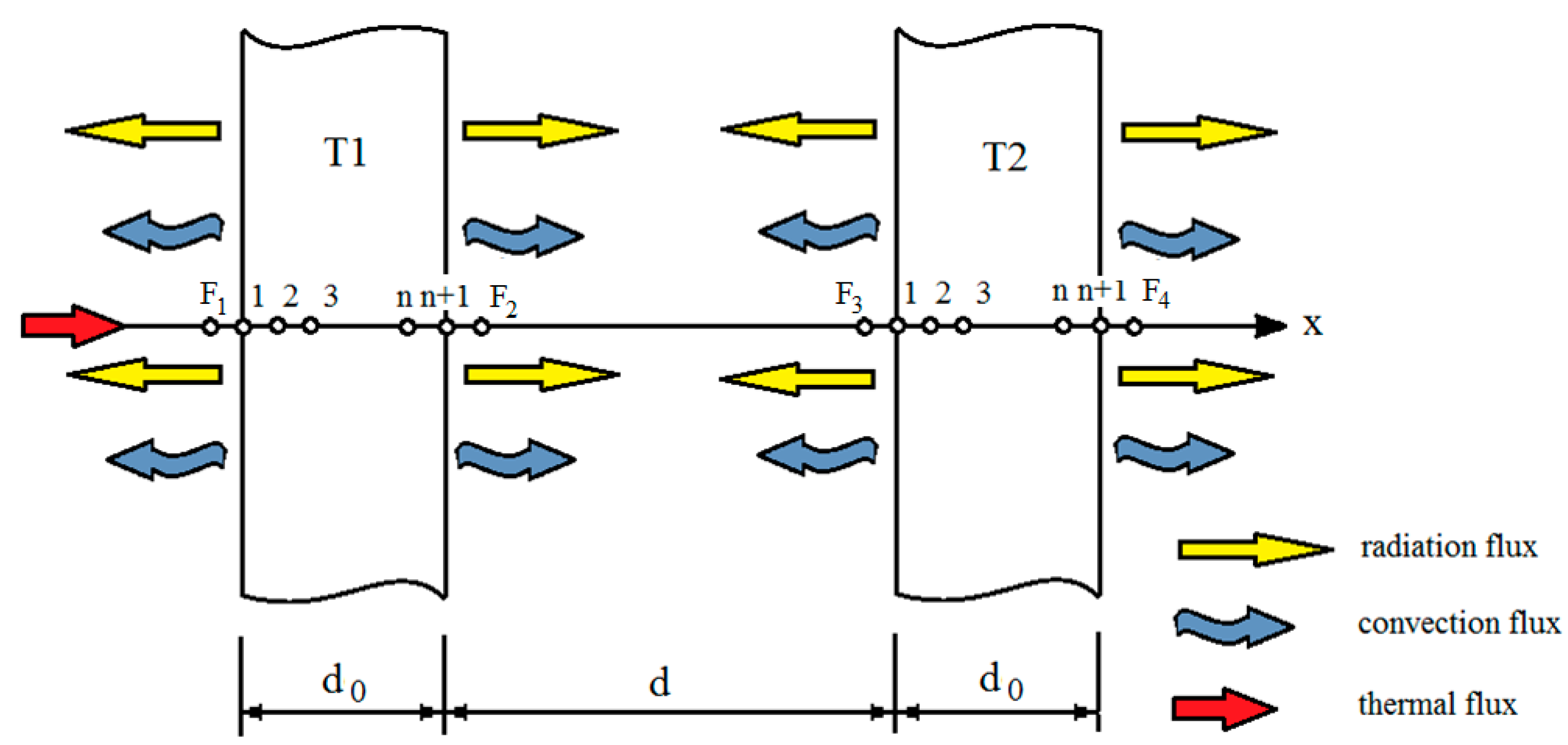
  • There will be two surface resistors for each plate of the heat shield and one for each radiation plane. When the emissivity of all surfaces is equal, then all surface resistances (2n + 2) will have the same value: 1 ε ε .
  • If there are (n + 1) spatial resistances, the configuration factor for each will be equal to the unit.
Therefore, the total strength of the physical system, for n plates forming a shield, will be
R ( n s h i e l d s ) = ( 2 n + 2 ) 1 ε ε + ( n + 1 ) 1 = ( n + 1 ) ( 2 ε 1 ) ,
so that the heat exchange is expressed by the following equation:
Q = 1 n + 1 A σ b ( T 1 4 T 2 4 ) ( 2 ε 1 ) .
The analytical model leads to the conclusion that n component plates in a heat shield reduce the transfer of radiant heat by a factor of (n + 1).

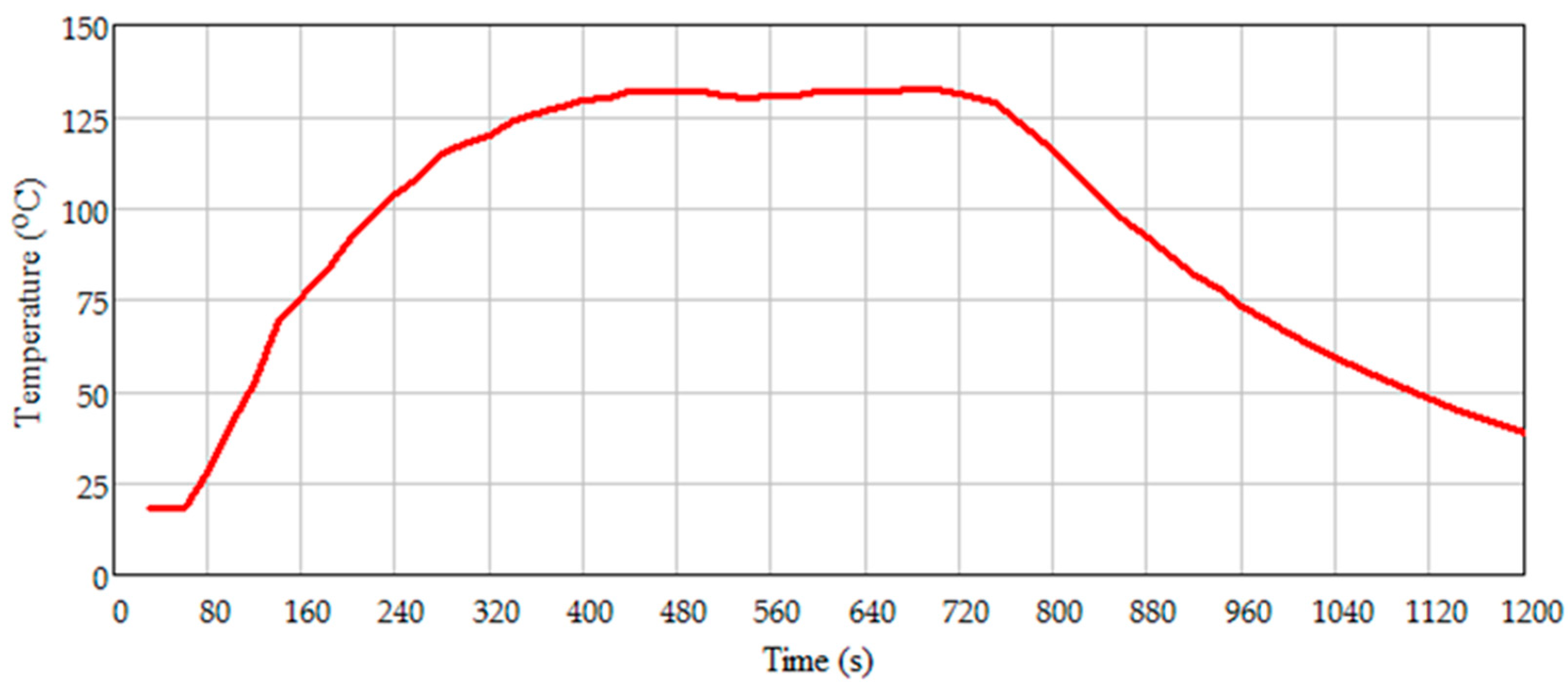
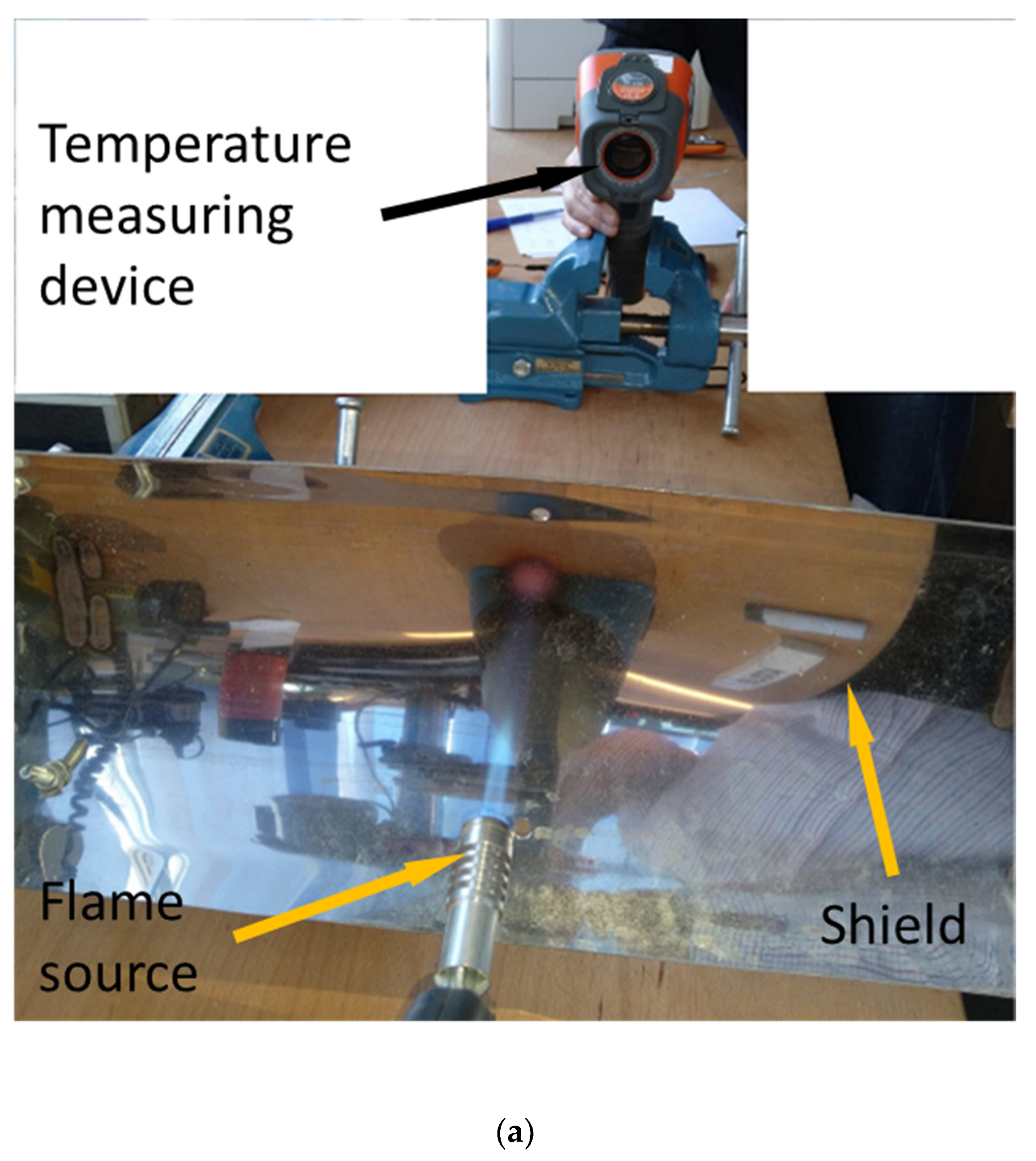
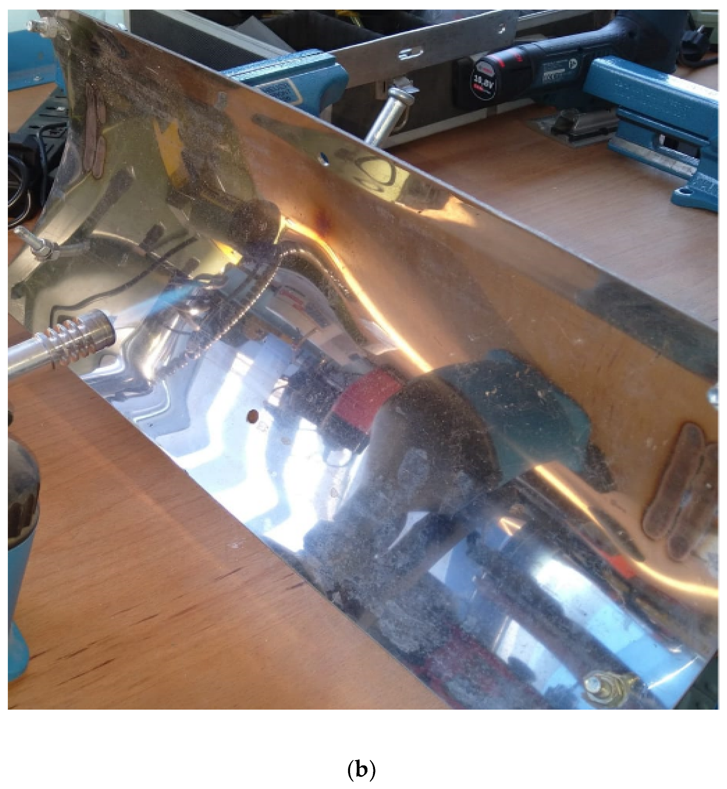
4. Experimental Study on the Behavior of the Thermal Shield to the Action of Fire

A flame obtained by burning liquefied petroleum gas (LPG), a mixture of hydrocarbons consisting predominantly of propane and butane, was used for the experiment. The flame jet was directed along the longitudinal axis of the shield. The plate was 2 mm thick 316L stainless steel. The Sonel KT-145 infrared thermometer was used to measure the temperature up to a maximum of 350 °C. The speed of the gas jet and the natural convective air currents were measured with the Testo 410i turbine anemometer. For the two tests, the same gas valve opening was used. The gas velocity was 3.4 m/s measured at a distance of 4 cm from the burner nozzle.
A first test was performed by exposing the concave face of a shield to an open flame 20 cm from the burner nozzle (Figure 3). The flame was maintained until a temperature of 350 °C was reached on the convex face. After reaching this temperature, the burner was stopped and measurement of the shield temperature was continued while cooling in the ambient air. An anemometer monitored the speed of the ascending hot air current.
The thermal imaging infrared camera was a Sonel KT 145, which had a measurement range from −20 to 350 °C and had an emissivity index that could be adjusted between 0.01 and 1.00. For stainless steel, we chose an emissivity of 0.15. The anemometer used was TESTO 410 I, which had a reference of 12.0 m/s at 24.8 °C and a tolerance of +/−0.4 m/s and +/−0.5 °C.
The thermal imaging chamber shows how the highest temperature on the convex side of the shield changed over time. In Figure 4, a temperature of 350 °C was observed within 14 s of exposure to an open flame.
The speed of the natural convective air was measured after the flame was closed so that the plastic turbine of the anemometer would not be exposed to high temperatures. Thus, the following values were determined, measured at 12 cm from the edge of the shield at the vertex, at the point of maximum temperature:
  • In the temperature range of 250–160 °C, the speed is about 0.6 m/s;
  • In the temperature range of 160–135 °C, the speed is about 0.5 m/s;
  • In the temperature range of 130–70 °C, the speed is about 0.4 m/s.
In this experiment, the temperature was transmitted by convection and radiation from high-temperature flue gases to the concave surface, by conduction in the shield from the concave to the convex face, and by convection to the air and radiation on the convex face. Due to the low temperature on the convex face (maximum 350 °C) and the short duration of the experiment, heat transfer by radiation was neglected.
In this study, the plate was heated for a very short time (20–24 s) when the temperature measured on the opposite side of the shield reached 350 °C, and the flame was turned off. The main heat transfer was by conduction. Only when the temperature exceeded 350 °C did radiation become significant. We also neglected radiation and assumed that the temperature was lost mainly by convection.
In the second experiment, two shields mounted 4 cm apart were used. The concave face of the first shield was exposed to open flames under the same conditions as in the first experiment, and the temperature was measured on the convex face of the second shield.
The transfer between the two shields was made by radiation and convection with a secondary input. The flame was maintained until a constant temperature was reached over time on the convex face of the second shield, i.e., for 660 s when the temperature stabilized at 132.5 °C.
Figure 5 shows the time variation of the maximum temperature on the convex face of the second shield.
The speed of the convective air was measured after the flame was closed, as in the first case. Thus, the following values were determined, as measured 12 cm from the edge of the shield at the vertical of the maximum temperature point:
  • From 132.5 to 100 °C, the speed was about 1.1 m/s near the first shield exposed to the flame and 0.6 m/s for the second;
  • From 100 to 80 °C, the speed was about 1 m/s near the first shield and 0.5 m/s for the second.

5. Analytical Model for the Non-Stationary Case of Heat Transfer by Radiation, Convection, and Conduction

To make a model of the experiments, the following known relationships about heat transfer were used:
T t = λ ρ c p ( 2 T x 2 + 2 T y 2 + 2 T z 2 )   and
q = α ( T w a l l T a i r )
for non-stationary heat transfers by conduction (for isotropic material through a shield), and heat transfer by radiation, respectively.
To simplify the model, the following hypotheses were made: the heat transfer is considered to be one-dimensional, and the shield plates are considered to be flat in a vertical position. The action of the flame on the shield was considered to be the action of a constant heat flow distributed uniformly over the entire face of the plate. Heat transfer by conduction was considered to be only in the normal direction on the shield, along the oX axis. Figure 5 shows the one-dimensional model for the first experiment, which was useful for estimating the heat flux coming from the action of the flame.
The differential equations were solved using the finite difference method (Figure 6). The wall thickness was divided into n equal intervals, n + 1 points, the distance between two points being denoted by hx. Two fictitious points were also used: F1 and F2 located the same distance (hx) from the walls.
Equation (13) is discretized with finite differences for any node i using differences centered along the x-axis and forward. The index “i” corresponds to the oX axis and “k” to time:
T i , k + 1 T i , k h t = a T i + 1 , k 2 T i , k + T i 1 , k h x 2 .
A default scheme results for an inner node in the wall, i = 2 … n:
T i , k + 1 = F o T i + 1 , k + ( 1 2 F o ) T i , k + F o T i 1 , k .
Using iteration Equation (16) it is possible to determine the temperatures in the inner nodes of the thermal shield. For node 1 on the left side of the shield, Equation (16) becomes
T 1 , k + 1 = F o T 2 , k + ( 1 2 F o ) T 1 , k + F o T F 1 , k .
The boundary condition for node 1, written for the time moment ht·k is
λ T 1 x = q e x t ( t i m e ) α ( T 1 T a m b ) ε σ 0 ( T 1 4 T a m b 4 ) .
The unknown T F 1 , k is determined from Equation (18) and replaced in Equation (17), thus resulting in the wall temperature, T 1 , k + 1 at time h t ( k + 1 ) . For the node n + 1 on the right side of the heat shield, the relationship between heat transfer by conduction and finite differences is:
T n + 1 , k + 1 = F o T n , k + ( 1 2 F o ) T n + 1 , k + F o T F 2 , k .
For the node n + 1 , the boundary condition at time h t k is
λ T n + 1 x = α ( T n + 1 T a m b ) + ε σ 0 ( T n + 1 4 T a m b 4 ) ,
which, when written with finite differences, becomes
λ T n , k T F 2 , k 2 h x = α ( T n + 1 , k T a m b ) + ε σ 0 ( T n + 1 , k 4 T a m b 4 ) .
The unknown T F 2 , k s was determined from Equation (19) and replaced in Equation (20), resulting in the temperature on the right side of the shield T n + 1 , k + 1 at time h t ( k + 1 ) . This way temperatures can be determined over time h t ( k + 1 ) in all outer and inner nodes of the shield if the temperatures are known at time h t k . The calculation started from the initial moment k = 0 when the temperature in all nodes was equal to that of the environment.
The convection heat transfer coefficient was calculated on the basis of the Nusselt, Grashof and Prandtl criteria for natural convection heat transfer in the case of vertically placed plates. Table 1 shows the calculation relationships.
For the Nusselt criterion ( N u = α L λ a i r ), the characteristic length L was considered to be 0.3 m, as the height of the plate. The Grashof criterion was defined as G r = g L 3 β a i r ( T w a l l T a m b ) ν a i r 2 , where β a i r is the coefficient of volumetric thermal expansion of the air; ν a i r is the kinematic viscosity of the air; g is the gravitational acceleration which depends on the temperature difference between the wall and the ambient temperature; and the Prandtl criterion Pr = ν a = μ c p λ .
The heat flow received from the outside varied according to the law
q e x t ( t i m e ) = { 122,000   i f   t i m e 24 0   i f   t i m e > 24 .
The intensity was chosen so that the temperature variation determined from the calculus corresponded to the experimental determinations in the time interval (0, 24) seconds. Figure 7 shows the numerically and experimentally determined variations on the right side of the shield. The correctness of considering the release of heat accumulated by the shield by convection and radiation was noted.
Figure 8 shows the percentage time error between experimental and numerical data.
For the second experiment, the model is shown in Figure 9. Heat flow was applied to the left sinus face of shield 1 where the temperature is denoted by T1. The right surface of shield 1 exchanged heat by radiation with the left sinus face of shield 2.
The boundary condition on the left side of shield 1 was similar to Equation (18), the only change being the notation (T is replaced by T1) and the law of variation of heat flux over time:
q e x t ( t i m e ) = { 122,000   i f   t i m e 660 0   i f   t i m e > 660 .
The boundary condition on the right side of shield 2 is similar to Equation (20), except the notation, T, was replaced by T2 and T F 2 , k by T F 4 , k .
On the right side of shield 1, the boundary condition was written:
λ T 1 n , k T F 2 , k 2 h x = α ( T 1 n + 1 , k T a m b ) + ε σ 0 2 + ε ( T 1 n + 1 , k 4 T 2 1 , k 4 )
and on the left side of shield 2,
λ T 2 2 , k T F 3 , k 2 h x = α ( T 2 1 , k T a m b ) + ε σ 0 2 + ε ( T 1 n + 1 , k 4 T 2 1 , k 4 ) .
These relationships permit the elimination of the unknowns T F 1 , k , T F 2 , k , T F 3 , k and T F 4 , k ; thus, it was possible to determine all nodal temperatures at time ht·(k + 1). Figure 10 shows the numerically and experimentally determined temperature variations on the right side of shield 2.
There was concordance between the temperature variation determined experimentally and that calculated numerically in the range of (0, 660). The numerical calculation showed that after the heat flow became zero, the shield cooled faster than in the experimental case. This was due to an overestimation of the coefficient α for high temperatures. The first shield reached a temperature exceeding 1000 °C (Figure 11), as the temperature in the second shield depended on that of the first shield.
Another factor influencing the result is the variation of the physical properties of stainless steel and air with temperature. In the calculations performed, the properties were considered constant.

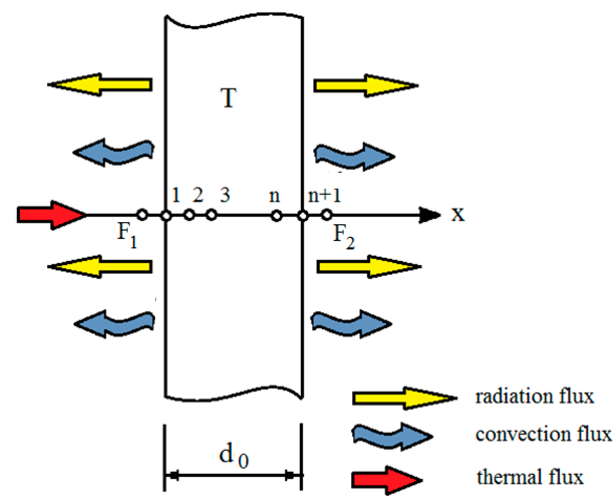
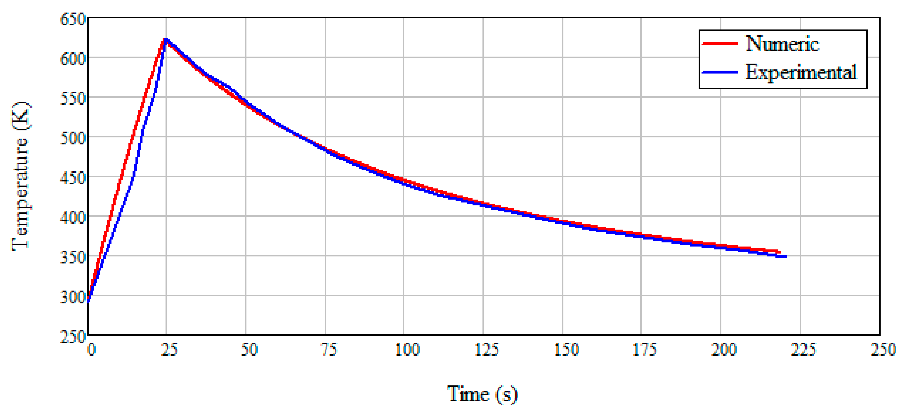
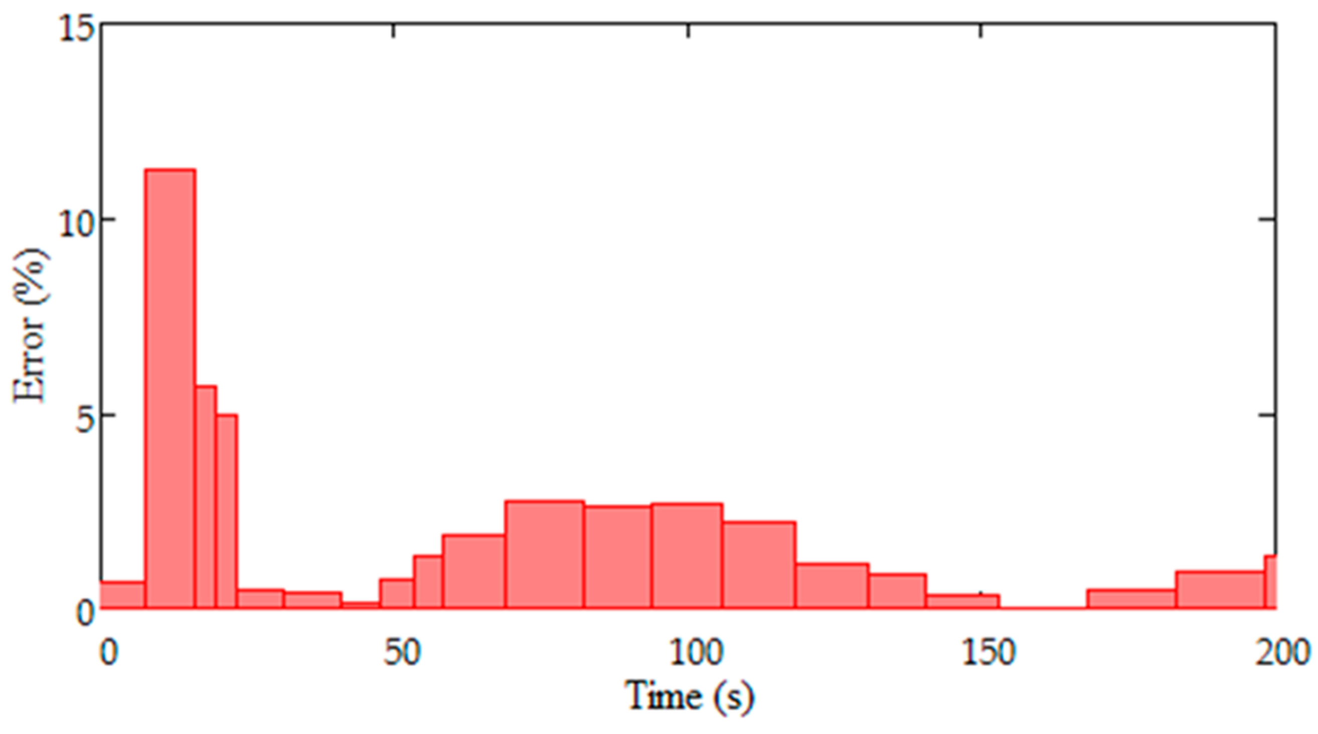
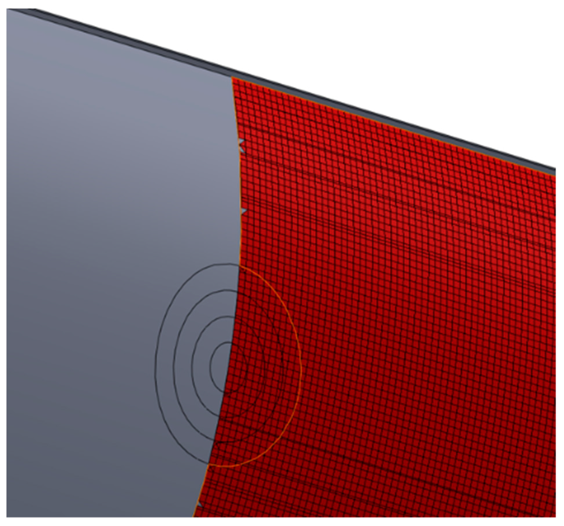
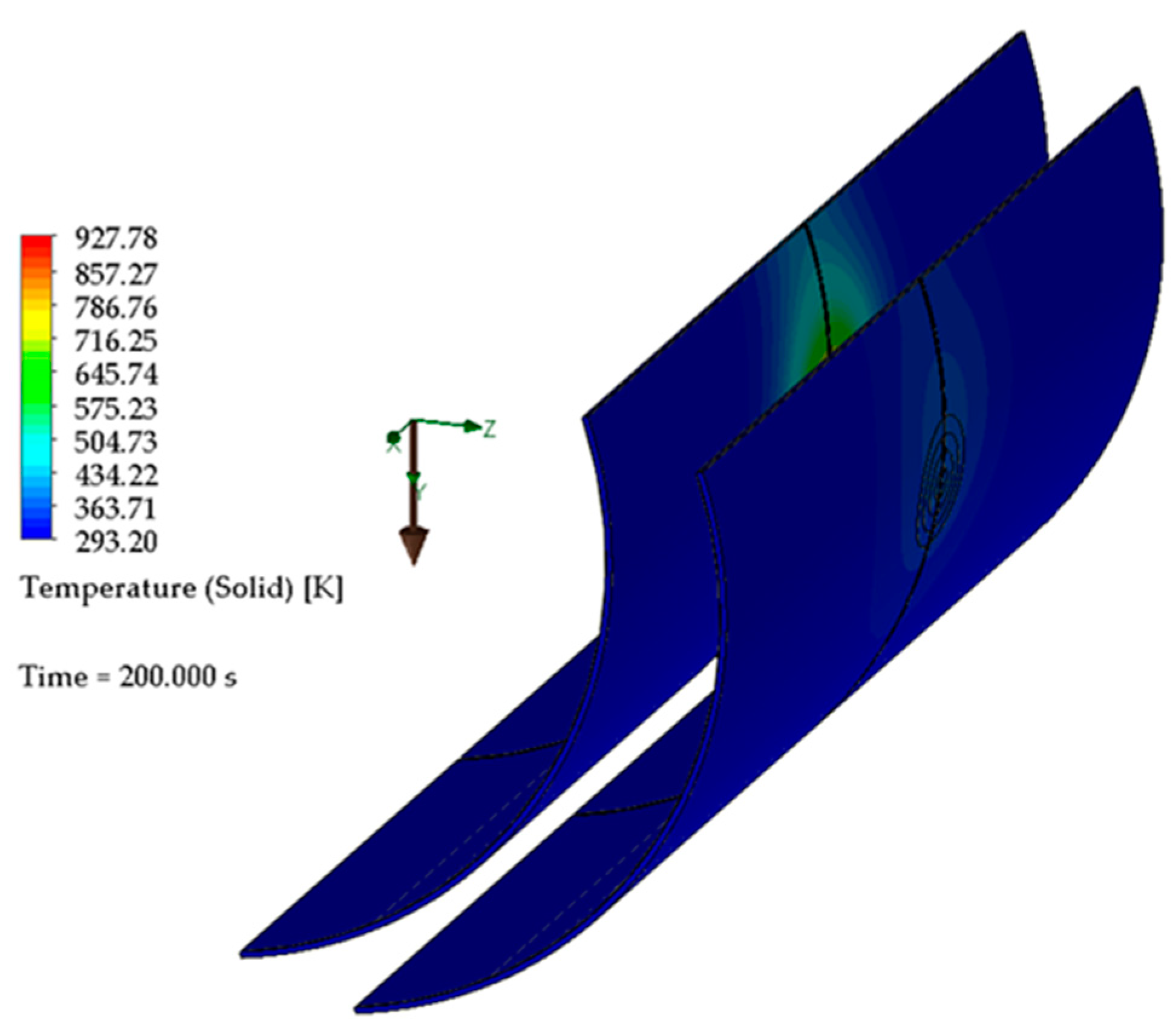
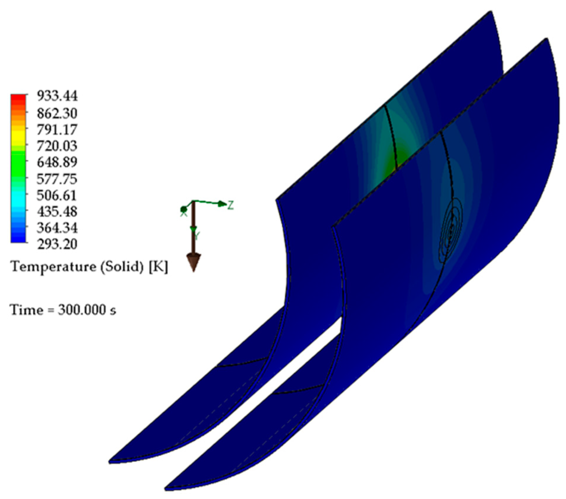
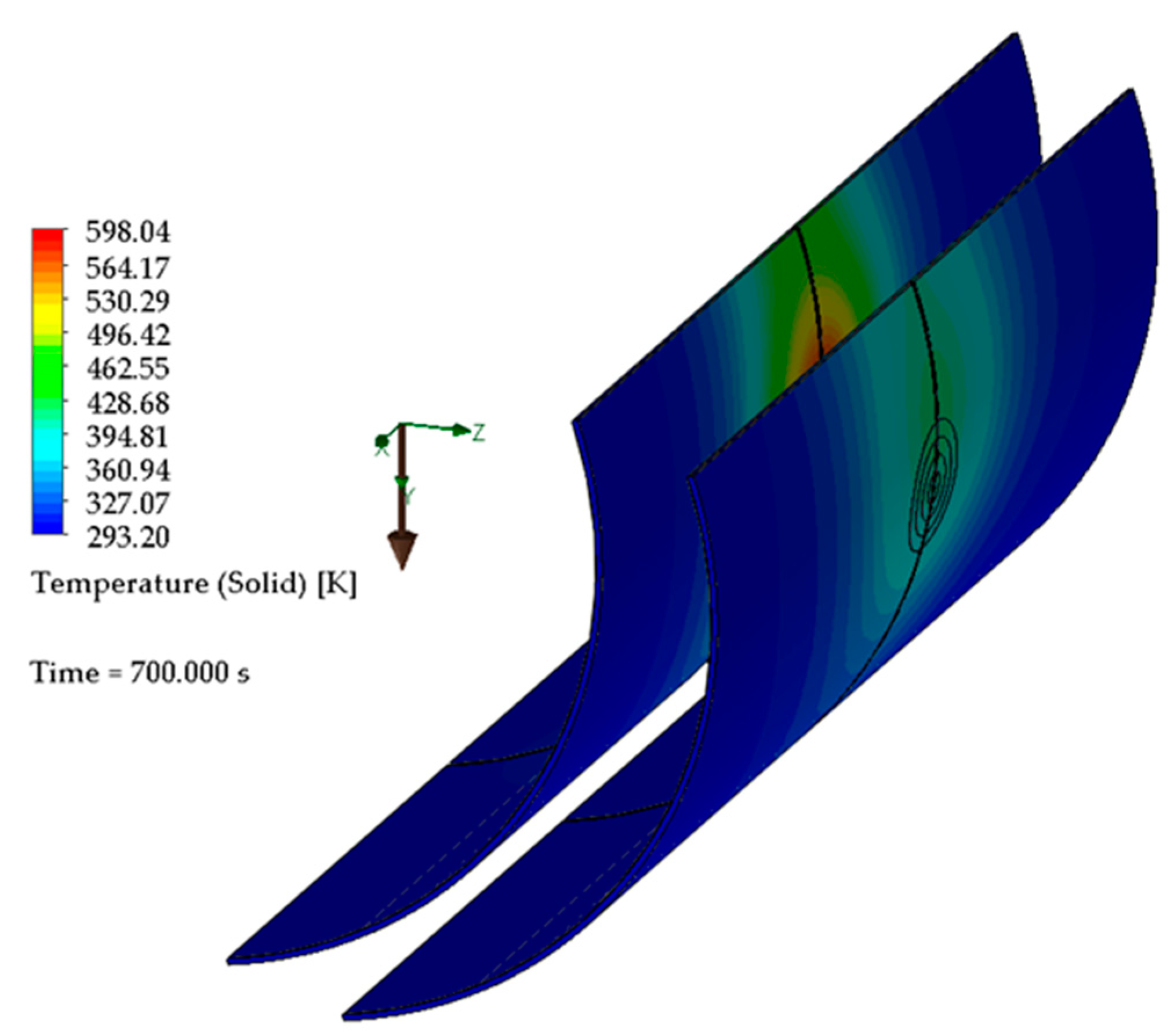
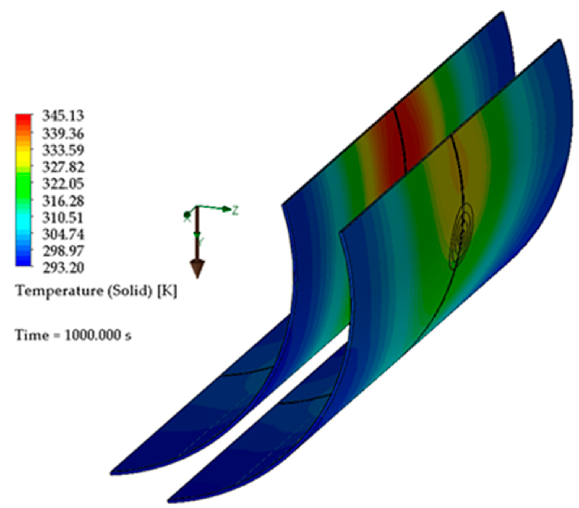
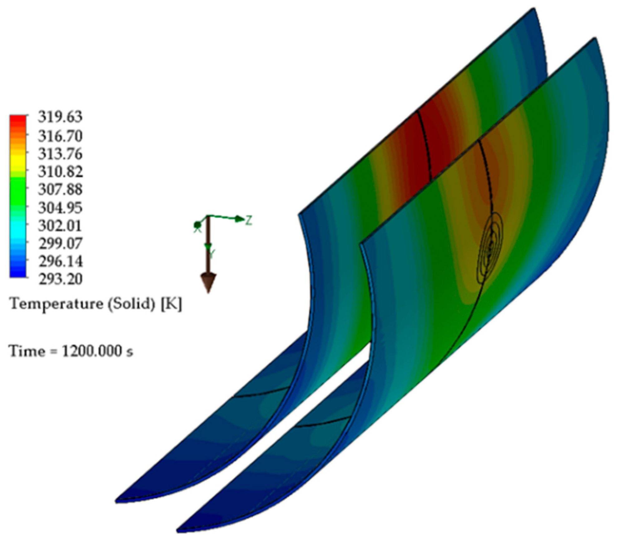
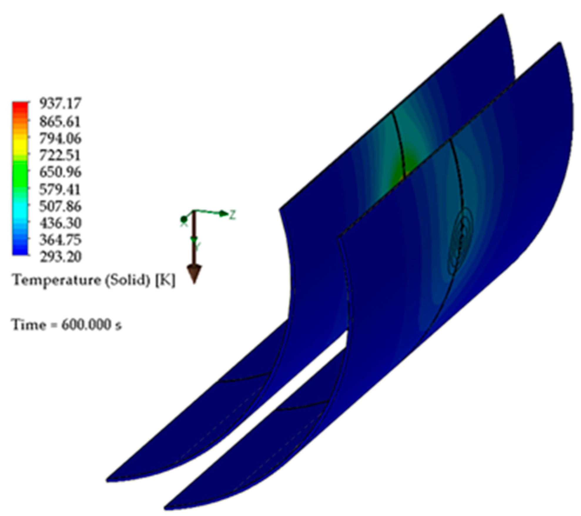
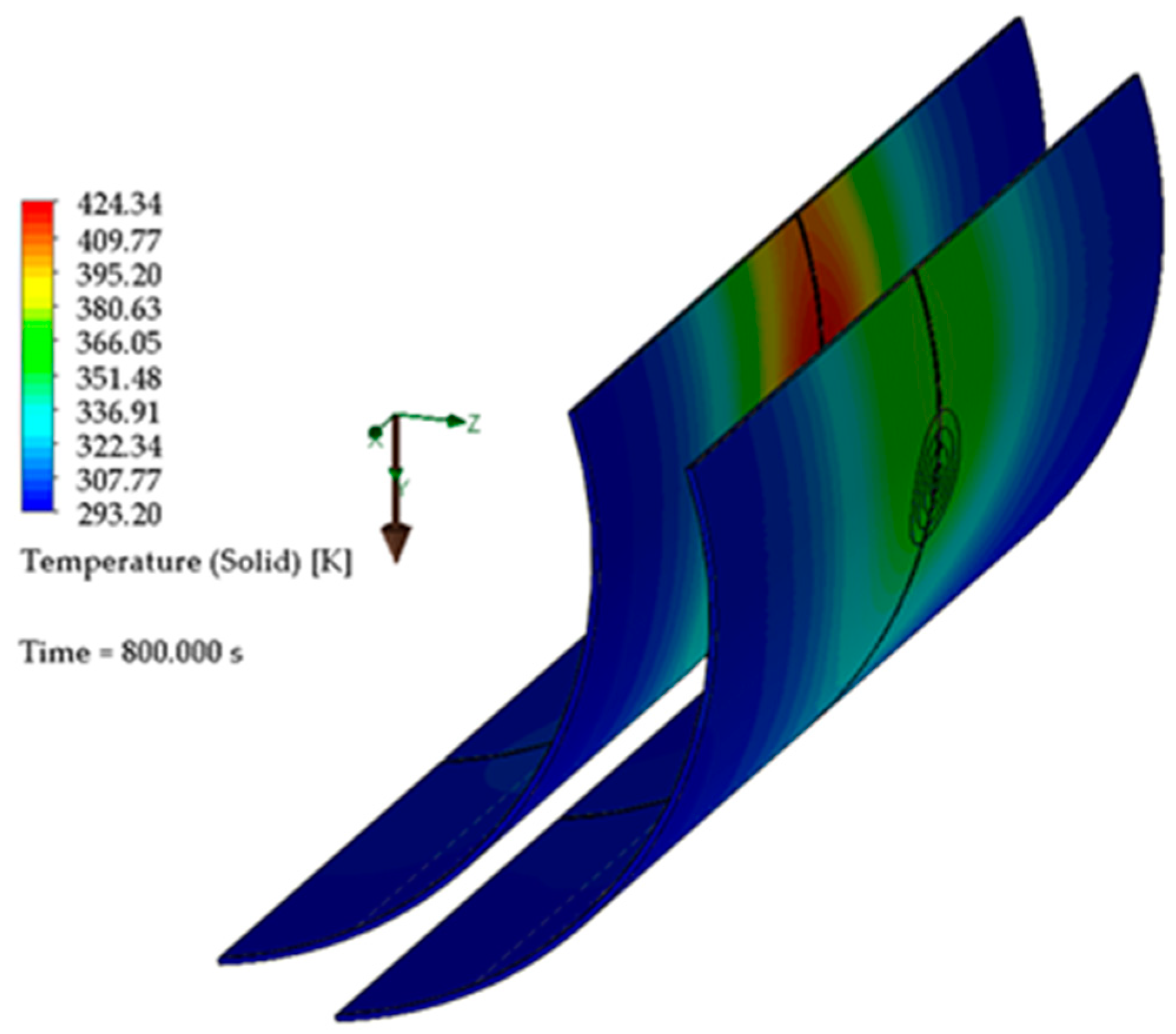
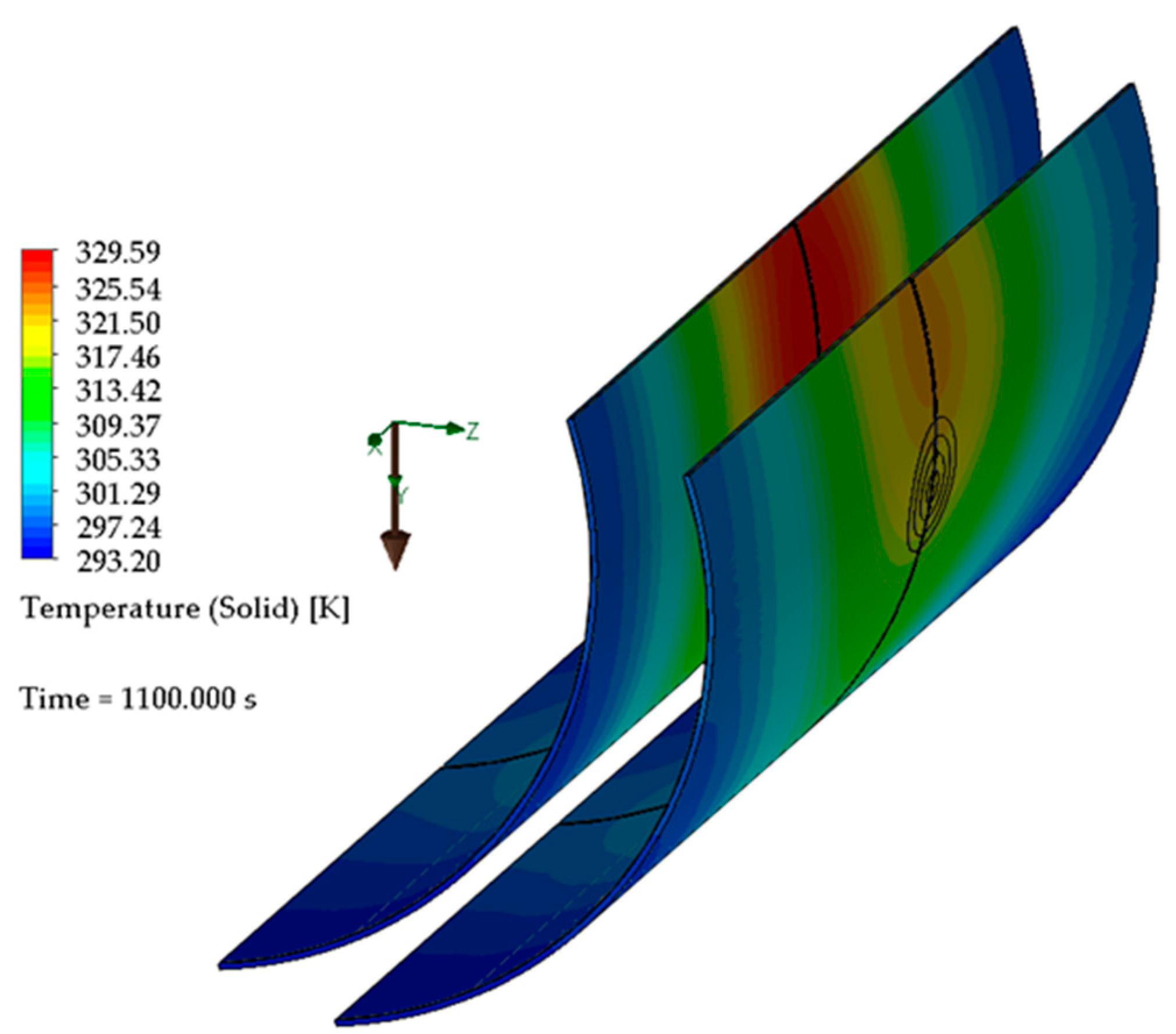
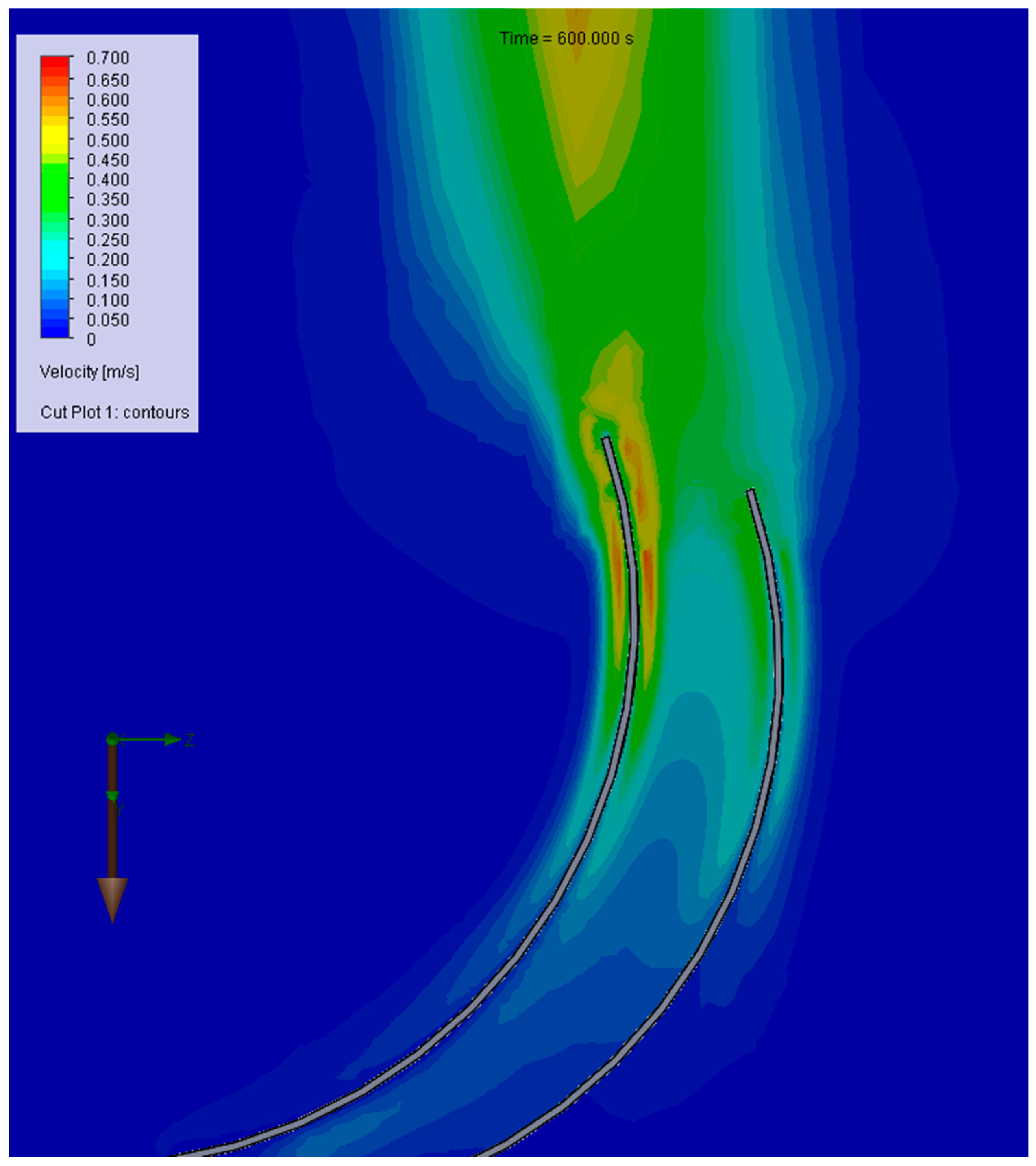
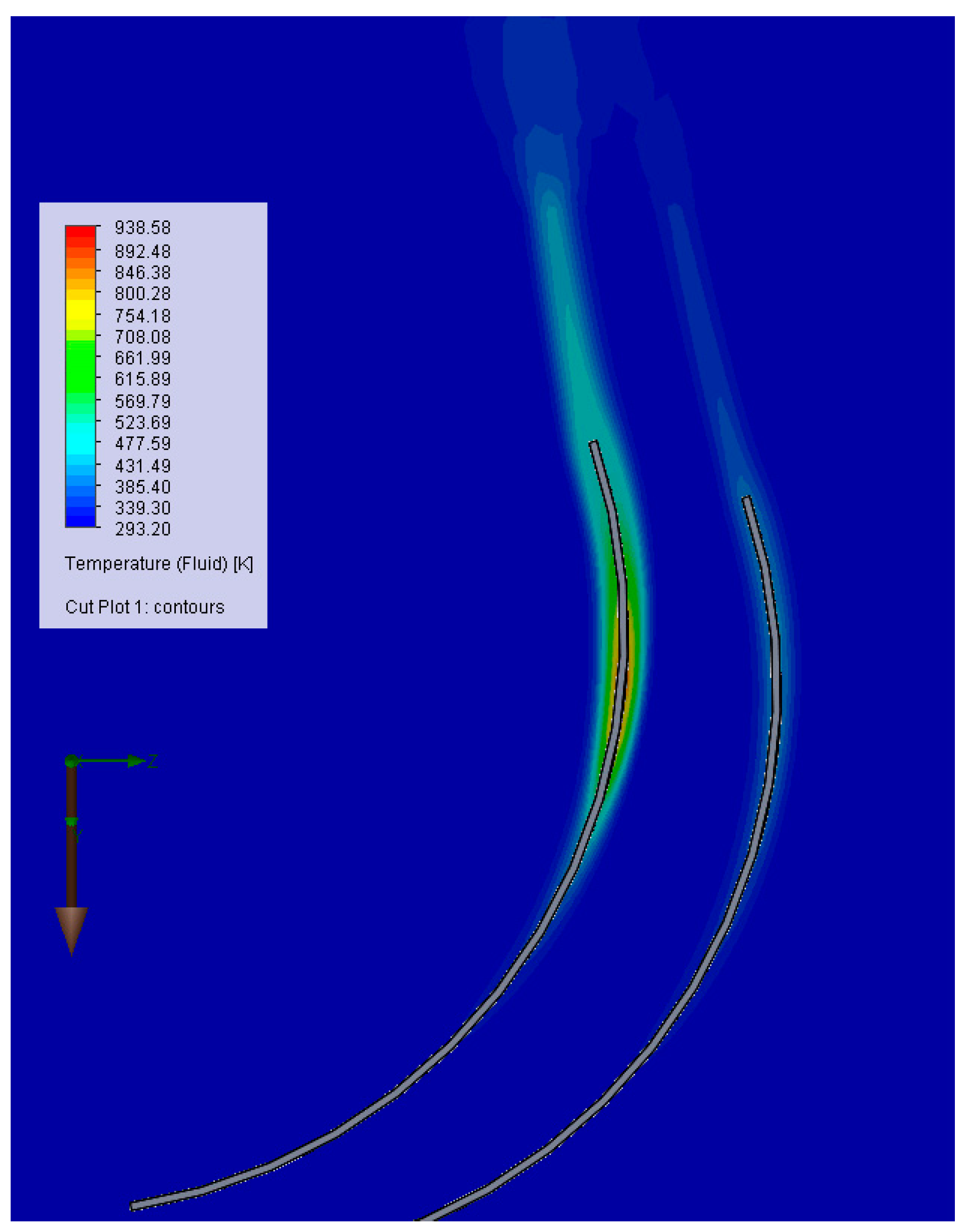
6. Transfer Modeling with the Finite Volume Method

The geometry of the two shields was implemented in SOLIDWORKS using a number of parameters that allowed changing the dimensions of the two shields and the relative position between them.
To model the heat transfer with the finite volume (VF) method, the geometric model shown in Figure 12 was used. In this model, circular surfaces were used to impose the heat flow that came from the action of the flame. The yOz plane has geometric and thermal symmetry.
FLOWORKS, the simulation module of the SOLIDWORKS software, was used to solve the model. The simulation was performed in a non-stationary regime, and for this study, the radiation options were activated. In the model, the air was implemented as an unstructured field, and the model contained two shields. The FLOWORKS module allowed the use of heat transfer through conduction, convection, and radiation. In the case of air, the density depended on the temperature, which led to the appearance of ascending currents due to the Archimedean forces. Gravitational acceleration was oriented in the positive direction of the oY axis. The initial conditions were as follows: the temperature was the same at all points of the shield, and the surrounding air was 293 K; the velocity of the surrounding air was 0 m/s, and the pressure was 1 atm. The fluid domain was a cube centered at the origin of the coordinate system with a side of 2 m. The faces of the cube were surfaces that could be crossed by air, from outside to inside and vice versa. The atmospheric pressure was 101,325 Pa and the temperature is 20 °C.
Figure 13 shows the mesh for the solid part. The total number of cells was 894,442 of which 91,830 were solid and 92,286 were mixed cells.
Figure 14, Figure 15, Figure 16, Figure 17, Figure 18, Figure 19, Figure 20, Figure 21, Figure 22, Figure 23, Figure 24 and Figure 25 show the temperatures of the two shields, a situation seen from the shield where the temperature was measured. The three elements of the robotic arm are clamped by means of the clamping lugs located on the rectangular pipe and on the clamping element located at the ends of the rotary motor assembly with linear motor (endless screw type).
The simulation showed the heat transfer by radiation from the first shield to the second. Transfer by conduction in the two shields was also observed, and the area with a high temperature in each shield increased with time. For the air flow velocities at free convection, there was a concordance between the calculated speeds and those determined experimentally. Figure 26 shows the velocity distribution on the symmetry plane.
Figure 27 and Figure 28 show the air temperatures and their density on the symmetry plane. There was a temperature of about 293 K between the two boards, which justified choosing it for the ambient temperature in the model with finite differences.
The variation in temperature over time is shown in Figure 29. It is noted in the numerical solution that the temperature reached equilibrium at the end of the period when the heat flux acted on the first shield and cooling occurred faster than in reality.

7. Conclusions

The benefit of using Computational Fluid Dynamics (CFD) is that compared with the finite difference model (one-dimensional, considering heat transfer only through the thickness of the plate) this one (with finite elements) was three-dimensional and highlighted heat transfer by conduction in the heat shields. Furthermore, the finite element model emphasized heat transfer by conduction in both transverse and longitudinal directions.
Although there were uncertainties [41] in current theoretical and computational models regarding the prediction of the evolution of thermal shields for mobile robots, the simulation responded quite well to real conditions:
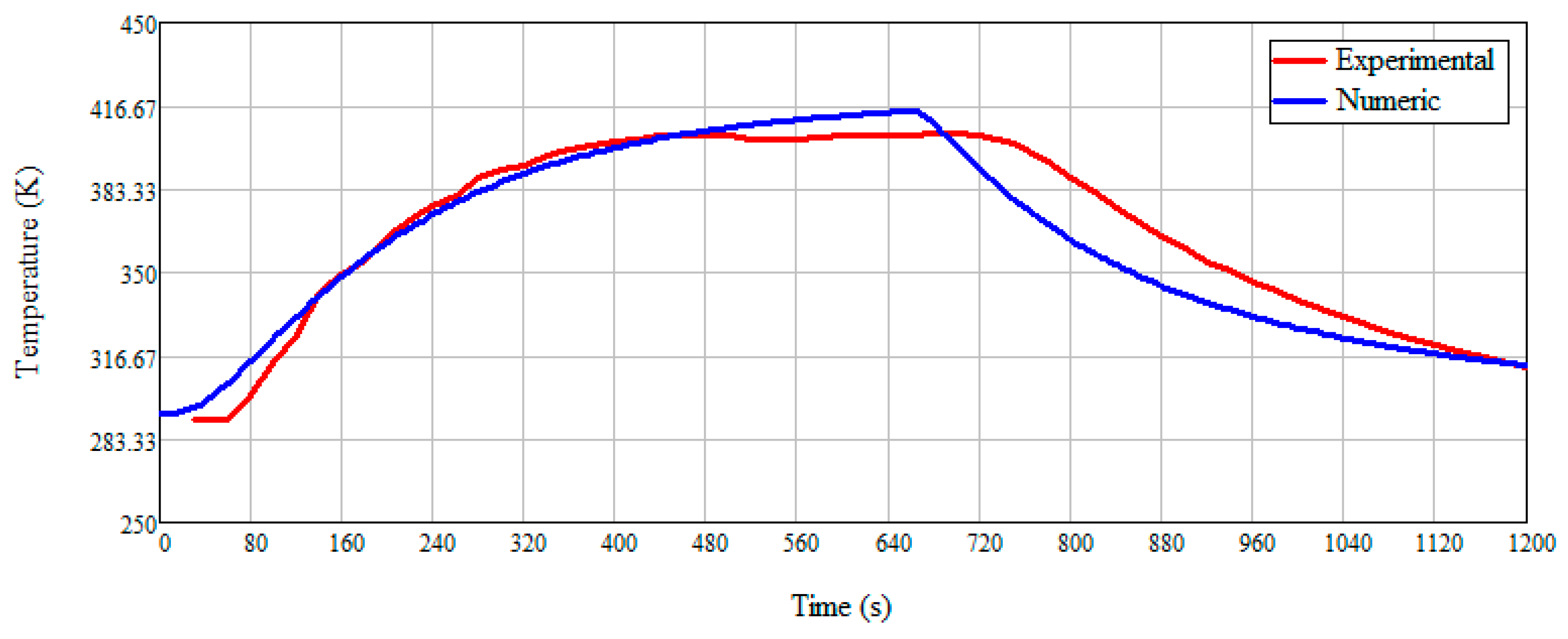
  • Estimating the evolution of temperature using analytical and numerical methods was satisfying, the most complex problems being related to convective heat transfer and determining the convection heat transfer coefficient;
  • Following the simulation, it was possible to identify parameters that needed to be measured to allow the correlation of calculations from the numerical analysis with the Finite Difference Method (FDM);
  • The evolution of the heating phenomenon over time showed us that, due to the special properties of stainless steel, temperature gradients increased moderately;
  • The introduction of the second wall to the protection shield demonstrated a decrease in temperature on the second shield, but under low ambient temperature;
  • Because the open flame was a hot air jet, the problem of a reverse analysis for modeling the gas fluid jet appeared, but this may be the subject of another research.
Uncertainty analysis refers to measurements, and we found that when using the measuring device, the reflection from the shield mirror introduced measurement errors, which we eliminated by changing the intensity of the light in the laboratory. In addition, the appearance of new images on the shield mirror (even the reflection of a person) led to an increase in the temperature read on the device. We repeated the measurements until we obtained two identical measurements.
The novelty of the multilayer shield concept with layers spaced 32 mm apart is that it allowed for a cooling gradient characterized by a decrease in temperature on the first shield from 346 to 320 K over a 1000 s exposure.
Our study made several relevant contributions to the way we chose the shield material; used analytical–numerical calculations to identify the distance between the two layers of the shield; designed the concavity of the shield so that the air currents would form as a result of temperature differences, thereby allowing us to obtain the results; and realized the analytical–numerical model, which allowed us to optimize the solution.
One of the important contributions was the development of a finite difference model for the one-dimensional case, which took into account heat transfer through conduction, convection, and radiation. The advantage of using this model is the reduced resolution time compared with the finite element model. On the other hand, it provided detailed results for the space case, allowing both temperature and velocity determination in the convective air stream.

8. Further Directions of Development

In future research, we intend to design and build a shield that can change its vertical position so that it no longer needs to be detached from the chassis. Another area is the study of other forms of shields and with several layers. The introduction of a smaller, water system to the second shield, the one facing the robot, is another area of research and development that we want to explore. Water or gas can be taken from the fire extinguishing system. In addition, we will add other sensors for measuring or filming the temperature, so that we have better control over the thermodynamic state of the robot.
The use of Sonel KT-145 infrared thermometer temperature sensors was not very suitable due to the maximum temperature that the device can measure. We propose the use of thermocouples, which will be used when operating the robot. These would allow permanent temperature monitoring and the decision to remove the robot from the source of thermal radiation if the temperature exceeds a critical threshold.
Another direction of development is to create a heterogeneous system of collaborative robots to intervene in firefighting. The heterogeneous character will be a product both of a multitude of integrated subsystems and the fact that each robot will have a different mission to fulfill.

Author Contributions

Conceptualization, A.Ș., L.Ș.G. and B.V.; methodology, I.O.; software, C.M., D.G. and D.C.; validation, A.Ș., L.Ș.G. and Ș.M.; formal analysis, D.C., R.-I.B. and Ș.M.; investigation, A.Ș., L.Ș.G. and D.C.; writing—original draft preparation, I.O. and C.M.; writing—review and editing, I.O. All authors have read and agreed to the published version of the manuscript.

Funding

This research received no external funding.

Acknowledgments

This paper benefited from material support and scientific consulting through the project with the following title Technological Demonstrator–Fire Extinguishing Robot, with the identification CEXLUM contract number 587/09.09.2014. Moreover, we thank the Research Centre of the Faculty of Informatics of Titu Maiorescu University, Bucharest, for the data from the “Fire Extinguishing Robot—Fire Fighting Robot FFR-1” project. The robot participated in the first PatriotFest competition https://www.patriotfest.ro/ (accessed on 22 August 2022) in November 2017 organized by the ministries of Defense, Home Affairs, Intelligence and their subsidiaries in partnership with the New Strategy Centre Association.

Conflicts of Interest

The authors declare no conflict of interest.

Abbreviations

AbbreviationsExplanation
σ = 5.67 10 8 [ W m 2 K 4 ] Stefan–Boltzmann’s constant
ε 1 , 2 [ W m 2 ] Emissivity
A 1 , 2 [ m 2 ] Surface
λ [ W mK ] Thermal conductivity coefficient
F [ ] Shape factor
EbBlackbody emissive power
c S [ J kgK ] Specific heat of stainless steel
ρ S [ kg m 3 ] Density of stainless steel
t [ s ] Time
T f [ ° C ] Temperature of the fire, at a certain moment
T S [ ° C ] Temperature in stainless steel considered uniform at the same time
H p [ m ] Perimeter
A g [ m 2 ] The gross cross-sectional area
H p A g [ m - 1 ] Factor of the section, namely the ratio between the heated perimeter
α c , r [ W m 2 K ] The heat transfer coefficient by convection and radiation
F o = a h t h x 2 Fourier number
a = λ c p ρ The thermal diffusivity coefficient
q e x t ( t i m e ) The heat flux received by the wall
α ( T 1 T a m b ) The convective heat flux from the wall to the external environment
ε σ 0 ( T 1 4 T a m b 4 ) The radiative heat flux

References

  1. Grigore, L.Ș.; Soloi, A.; Tiron, O.; Răcuciu, C. Fundamentals of Autonomous Robot Classes with a System of Stabilization of the Gripping Mechanism. In Proceedings of the 2012 International Conference on Nano Materials and Electric Devices (ICNMED 2012), Hong Kong, China, 19–20 December 2012; Volume 646, pp. 164–170. [Google Scholar]
  2. Nuță, I.; Orban, O.; Grigore, L.Ș. Development and improvement of technology in emergency response. Procedia Econ. Financ. 2015, 32, 603–609. [Google Scholar] [CrossRef] [Green Version]
  3. Peskoe-Yang, L. Paris Firefighters Used This Remote-Controlled Robot to Extinguish the Notre Dame Blaze. In IEEE Spectrum: Technology, Engineering, and Science News; 2019; Available online: https://spectrum.ieee.org/colossus-the-firefighting-robot-that-helped-save-notre-dame (accessed on 13 October 2022).
  4. Raghavendran, P.S.; Suresh, M.; Ranjith Kumar, R.; Ashok Kumar, R.; Mahendran, K.; Swathi, S.; Kamesh, L.; Sanjay, R. An Intelligent Remote-Controlled Fire Fighting Machine for Autonomous Protection of Human being. Int. J. Adv. Res. Sci. Eng. Technol. 2018, 5, 7620–7626. [Google Scholar]
  5. Nikitin, V.; Golubin, S.; Belov, R.; Gusev, V.; Andrianov, N. Development of a robotic vehicle complex for wildfire-fighting by means of fire-protection roll screens. IOP Conf. Ser. Earth Environ. Sci. 2019, 226, 012003. [Google Scholar] [CrossRef]
  6. Steopan, M.; Schonstein, C.; Bogdan, A.V. Mobile Robotic Platform for Firefighting—Concept Development, Finissing and Mockup Buildup. J. Acta Tech. Napoc. Ser. Appl. Math. Mech. Eng. 2020, 63, 269–274. [Google Scholar]
  7. Kurvinen, K.; Smolander, P.; Pöllänen, R.; Kuukankorpi, S.; Kettunen, M.; Lyytinen, J. Design of a Radiation Surveillance Unit for an Unmanned Aerial Vehicle. J. Environ. Radioact. 2005, 81, 1–10. [Google Scholar] [CrossRef]
  8. Zhang, K.; Hutson, C.; Knighton, J.; Hermann, G.; Scott, T. Radiation Tolerance Testing Methodology of Robotic Manipulator Prior to Nuclear Waste Handling. Front. Robot. AI 2020, 7, 10. [Google Scholar] [CrossRef] [PubMed] [Green Version]
  9. Zhu, J.; Pan, L.; Zhao, G. An Improved Near-Field Computer Vision for Jet Trajectory Falling Position Prediction of Intelligent Fire Robot. Sensors 2020, 20, 7029. [Google Scholar] [CrossRef]
  10. Anderson, J.; Lee, D.J.; Schoenberger, R.; Wei, Z.; Archibald, Z.K. Semi-Autonomous Unmanned Ground Vehicle Control System. In Unmanned Systems Technology VIII, Proceedings of the Defense and Security Symposium, Orlando (Kissimmee), FL, USA, 17–21 April 2006; Society of Photo Optical: Bellingham, WA, USA, 2006. [Google Scholar]
  11. Grigore, L.Ș.; Priescu, I.; Joița, D.; Holban-Oncioiu, I. The Integration of Collaborative Robot Systems and Their Environmental Impacts. Processes 2020, 8, 494. [Google Scholar] [CrossRef] [Green Version]
  12. Cruz, H.; Eckert, M.; Meneses, J.; Martínez, J.-F. Efficient Forest Fire Detection Index for Application in Unmanned Aerial Systems (UASs). Sensors 2016, 16, 893. [Google Scholar] [CrossRef] [Green Version]
  13. Sousa, M.J.; Moutinho, A.; Almeida, M. Thermal Infrared Sensing for Near Real-Time Data-Driven Fire Detection and Monitoring Systems. Sensors 2020, 20, 6803. [Google Scholar] [CrossRef]
  14. Kwet, C.; Lam, Y.; Man, L.; Koonjul, Y.; Nagowah, L. A low cost autonomous unmanned ground vehicle. Future Comput. Inform. J. 2018, 3, 304–320. [Google Scholar]
  15. Muppidi, S. Development of a Low Cost Controller and Navigation System for Unmanned Ground Vehicle. Master’s Thesis, West Virginia University, Morgantown, West Virginia, 2008. [Google Scholar] [CrossRef]
  16. Patle, B.K.; Ganesh-Babu, L.; Pandey, A.; Parhi, D.R.K.; Jagadeesh, A. A review: On path strategies for navigation of mobile robot. Def. Technol. 2019, 15, 582–606. [Google Scholar] [CrossRef]
  17. Väljaots, E.; Sell, R.; Kaeeli, M. Motion and Energy Efficiency Parameters of Unmanned Ground Vehicle. Solid State Phenom. 2015, 220–221, 934–939. [Google Scholar]
  18. Sevinchan, E. Investigation of Thermal Management Options for Robots. Ph.D. Thesis, University of Ontario Institute of Technology, Oshawa, ON, Canada, 2018. [Google Scholar]
  19. Szrek, J.; Zimroz, R.; Wodecki, J.; Michalak, A.; Góralczyk, M.; Worsa-Kozak, M. Application of the Infrared Thermography and Unmanned Ground Vehicle for Rescue Action Support in Underground Mine—The AMICOS Project. Remote Sens. 2021, 13, 69. [Google Scholar] [CrossRef]
  20. Ștefan, A.; Ștefan, A.; Constantin, D.; Mateescu, C.; Cartal, L.A. Aspects of kinematics and dynamics for Payload UAVs. In Proceedings of the 7th International Conference on Electronics, Computers and Artificial Intelligence (ECAI), Bucharest, Romania, 25–27 June 2015; pp. WF1–WF4. [Google Scholar]
  21. Wong, J.Y. Terramechanics and Off-Road Vehicle Engineering: Terrain Behaviour, Off-Road Vehicle Performance and Design, 2nd ed.; Butterworth-Heinemann Elsevier Ltd.: Oxford, UK, 2009; p. 488. [Google Scholar]
  22. Ciobotaru, T. Semi-Empiric Algorithm for Assessment of the Vehicle Mobility. Leonardo Electron. J. Pract. Technol. 2009, 8, 19–30. [Google Scholar]
  23. Alexa, O.; Coropețchi, I.; Vasile, A.; Oncioiu, I.; Grigore, L.Ș. Considerations for Determining the Coefficient of Inertia Masses for a Tracked Vehicle. Sensors 2020, 20, 5587. [Google Scholar] [CrossRef]
  24. Ott, C.W.; Adhikari, B.; Alexander, S.P.; Hodza, P.; Xu, C.; Minckley, T.A. Predicting Fire Propagation across Heterogeneous Landscapes Using WyoFire: A Monte Carlo-Driven Wildfire Model. Fire 2020, 3, 71. [Google Scholar] [CrossRef]
  25. Cicione, A.; Gibson, L.; Wade, C.; Spearpoint, M.; Walls, R.; Rush, D. Towards the Development of a Probabilistic Approach to Informal Settlement Fire Spread Using Ignition Modelling and Spatial Metrics. Fire 2020, 3, 67. [Google Scholar] [CrossRef]
  26. Castro Jiménez, L.E.; Edgar, A. Martínez-García, E.A. Thermal Image Sensing Model for Robotic Planning and Search. Sensors 2016, 16, 1253. [Google Scholar] [CrossRef] [PubMed] [Green Version]
  27. Le, Q.X.; Dao, V.T.N.; Torero, J.L.; Maluk, C.; Bisby, L. Effects of temperature and temperature gradient on concrete performance at elevated temperatures. Adv. Struct. Eng. 2018, 21, 1223–1233. [Google Scholar] [CrossRef] [Green Version]
  28. IMOA—International Molybdenum Association. Stainless Steel Fire Performance & Radiant Heat Transfer. Available online: https://www.imoa.info/molybdenum-uses/molybdenum-grade-stainless-steels/architecture/fire-resistance.php (accessed on 13 January 2021).
  29. Li, S.; Feng, C.; Niu, Y.; Shi, L.; Wu, Z.; Song, H. Reconnaissance Robot Based on SLAM Position, Thermal Imaging Technologies, and AR Display. Sensors 2019, 19, 5036. [Google Scholar] [CrossRef] [Green Version]
  30. Agarwal, N.; Rohilla, Y. Flame Sensor Based Atunomous Firefighting Robot. In Proceedings of the Fifth International Conference on Microelectronics, Computing and Communication Systems, Proceeding of the Fifth International Conference on Microelectronics, Computing and Communication Systems (MCCS-2020), Ranchi, India, 21–22 October 2020; Springer Nature Singapore Pte Ltd.: Singapore, Singapore, 2021; Volume 748, pp. 641–655. [Google Scholar] [CrossRef]
  31. Brucker, K.A.; Majdalani, J. Effective thermal conductivity of common geometric shapes. Int. J. Heat Mass Transf. 2005, 48, 4779–4796. [Google Scholar] [CrossRef]
  32. Ryzhenkov, A.V.; Pogorelov, S.I.; Loginova, N.A.; Mednikov, A.F.; Tkhabisimov, A.B. Radiant heat transfer reduction methods in heat insulation of power equipment. WIT Trans. Eng. Sci. 2016, 106, 107–114. [Google Scholar]
  33. Tahmasbi, V.; Noori, S. Thermal Analysis of Honeycomb Sandwich Panels as Substrate of Ablative Heat Shield. J. Thermophys. Heat Transf. 2017, 32, 129–140. [Google Scholar] [CrossRef]
  34. SMOOTH–Smart Robots for Fighting. Available online: https://ec.europa.eu/research/participants/documents/downloadPublic?documentIds=080166e5bb6ea8f9&appId=PPGMS (accessed on 14 January 2021).
  35. Tan, C.F.; Liew, S.M.; Alkahari, M.R.; Ranjit, S.S.S.; Said, M.R.; Chen, W.; Rauterberg, G.W.M.; Sivakumar, D. Fire Fighting Mobile Robot: State of the Art and Recent Development. Aust. J. Basic Appl. Sci. 2013, 7, 220–230. [Google Scholar]
  36. Liu, P.; Yu, H.; Cang, S.; Vladareanu, L. Robot-Assisted Smart Firefighting and Interdisciplinary Perspectives. In Proceedings of the 22nd International Conference on Automation and Computing (ICAC), Colchester, UK, 7–8 September 2016; pp. 395–401. [Google Scholar]
  37. Grigore, L.Ș.; Priescu, I.; Grecu, D.L. Applied Artificial Intelligence in Fixed and Mobile Robotic Systems. Cap 4 Terrestrial Mobile Robots; AGIR: Bucharest, Romania, 2020; p. 703. ISBN 978-973-72-0767-8. [Google Scholar]
  38. Silk, E. Radiative Heat Transfer Analysis. In Introduction to Spacecraft Thermal Design; Cambridge Aerospace Series; Cambridge University Press: Cambridge, UK, 2020; pp. 64–113. [Google Scholar] [CrossRef]
  39. Leca, A.; Chiriac, F.; Pop, M.; Badea, L. Heat Transfer Processes; Technical Publishing House: Bucharest, Romania, 2000. [Google Scholar]
  40. Croft, D.R.; David, G. Lilley, Heat Transfer Calculations Using Finite Difference Equations; Elsevier Science & Technology: London, UK, 1977; p. 283. [Google Scholar]
  41. Robert, J. Moffat, Describing the uncertainties in experimental results. Exp. Therm. Fluid Sci. 1988, 1, 3–17. [Google Scholar] [CrossRef]
Figure 1. Radiation Shield between two parallel planes.
Machines 10 00942 g001
Figure 2. Robotic fire extinguisher with thermal protection shield.
Machines 10 00942 g002
Figure 3. The single shield experiment. (a) the representation of the heat shield temperature measurement system. At the top of the figure is the Sonel KT-145 temperature measuring device. At the bottom the heat shield and the open flame lamp. (b) the material from which the shield is made has a high reflection index.
Machines 10 00942 g003aMachines 10 00942 g003b
Figure 4. The time variation of the maximum temperature on the convex face of the shield when it was exposed to an open flame.
Machines 10 00942 g004
Figure 5. Time variation of the maximum temperature on the convex face of the second shield.
Machines 10 00942 g005
Figure 6. Scheme with finite differences.
Machines 10 00942 g006
Figure 7. Numerical and experimental temperature variations over time on the right side of the heat shield.
Machines 10 00942 g007
Figure 8. The percentage error in time between the experimental and numerical data.
Machines 10 00942 g008
Figure 9. Discretization with nodes for the second experiment.
Machines 10 00942 g009
Figure 10. Temperature variations on the right side of shield 2, determined numerically and experimentally.
Machines 10 00942 g010
Figure 11. Maximum temperature variation in the first shield.
Machines 10 00942 g011
Figure 12. Shield geometry and fluid domain.
Machines 10 00942 g012
Figure 13. Volume elements at the shield surface on the symmetry domain.
Machines 10 00942 g013
Figure 14. Temperature at 100 s.
Machines 10 00942 g014
Figure 15. Temperature at 200 s.
Machines 10 00942 g015
Figure 16. Temperature at 300 s.
Machines 10 00942 g016
Figure 17. Temperature at 400 s.
Machines 10 00942 g017
Figure 18. Temperature at 500 s.
Machines 10 00942 g018
Figure 19. Temperature at 600 s.
Machines 10 00942 g019
Figure 20. Temperature at 700 s.
Machines 10 00942 g020
Figure 21. Temperature at 800 s.
Machines 10 00942 g021
Figure 22. Temperature at 900 s.
Machines 10 00942 g022
Figure 23. Temperature at 1000 s.
Machines 10 00942 g023
Figure 24. Temperature at 1100 s.
Machines 10 00942 g024
Figure 25. Temperature at 1200 s.
Machines 10 00942 g025
Figure 26. Distribution of velocities on the symmetry plane.
Machines 10 00942 g026
Figure 27. Air temperature at 660 s.
Machines 10 00942 g027
Figure 28. Air density at 660 s.
Machines 10 00942 g028
Figure 29. Maximum temperature variation on the second shield.
Machines 10 00942 g029
Table 1. The calculation relationships.
The Nusselt Criterion (Nu)Conditions
1 N u = 1 , 18 ( G r Pr ) 0.125 10 3 G r . Pr < 500
2 N u = 0.54 ( G r Pr ) 0.25 500 G r . Pr < 2 10 8
3 N u = 0.59 ( G r Pr ) 0.25 2 10 8 G r . Pr < 10 9
Publisher’s Note: MDPI stays neutral with regard to jurisdictional claims in published maps and institutional affiliations.

