
Development of a Worker-Following Robot System: Worker Position Estimation and Motion Control under Measurement Uncertainty


1
School of Mechanical Engineering, Pukyong National University, Busan 48513, Republic of Korea
2
Major of Control and Instrumentation Engineering, Pukyong National University, Busan 48513, Republic of Korea
*
Author to whom correspondence should be addressed.
Machines 2023, 11(3), 366; https://doi.org/10.3390/machines11030366
Submission received: 7 February 2023
/
Revised: 2 March 2023
/
Accepted: 7 March 2023
/
Published: 8 March 2023
(This article belongs to the Special Issue Heterogeneity in Intelligent Mobile Robots and Systems)
Abstract
:This study proposes a sensor data process and motion control method for a mobile platform essential for transporting finished products or subsidiary materials in a smart factory. We developed a system that recognizes a fiducial marker printed on the work clothes worn by a worker, estimates the worker’s location, and follows the worker using the estimated location. To overcome the limitations of simulation-based research, gait data on a two-dimensional plane were derived through a human gait model and an error model according to the distance between the image sensor and the reference marker. The derived gait data were defined as the localization result for the worker, and a Kalman filter was used to robustly address the uncertainty of the localization result. A virtual spring-damper system was applied to follow the Mecanum wheel-based mobile platform workers. The performance of the proposed algorithm was demonstrated through comparative simulations with existing methods.
1. Introduction
With the breakthrough of robot automation technology, artificial intelligence technology, and communication technology, mobile robot-based services are being provided in various areas of society. In particular, as we enter the era of the Fourth Industrial Revolution, robots are being introduced at many production sites [1]. At a production site, the logistics regarding parts and final products play an important role in the production process. In the early stage of robot automation, AGVs (automated guided vehicles), which move only in designated areas, were used to manage logistics at the production site. However, AMRs (autonomous mobile robots) have recently replaced them in this role. These changes were made possible by the improvement of robot recognition technology based on artificial intelligence, the improvement of the self-localization functions of robots through high-speed communication, and the development of control technology. As a result, deploying AMRs at the production site makes it possible to respond flexibly to changes in the production environment and work process [2]. Among the various types of AMRs, mobile platforms that follow workers and help to transport heavy objects are becoming very important in industrial sites where workers and robots work together. Technically, it is possible to develop fully autonomous production lines. Still, industrial sites are currently maintaining the roles of workers to protect their occupational rights and to be able to respond to errors that may occur with autonomous systems. The important skills for a human-following robot are human recognition and tracking control. This technology is also considered one of the top priorities in the era of COVID-19 [3]. There have been numerous studies on technology for stably recognizing people. One category of human recognition is recognizing and following people using Lidar. Ref. [4] utilized a laser range finder (LRF) to recognize human legs. Chung et al. [5] proposed detection and tracking schemes for human legs using a single laser range finder. A marathon service robot was developed using an LRF [6]. Refs. [7,8] proposed an off-line trained full convolutional neural network to improve peoples’ leg tracking performance with a 2D Lidar. While Lidar has the advantage of enabling human recognition and tracking through a low-cost sensor and small memory, its limitation is that it is impossible to recognize a specific person using it; this makes it easy to lose the target. To complement these Lidar-based recognition technologies, image-based human recognition technologies have been developed in parallel. Bodor et al. [9] accomplished a tracking algorithm by developing a position and velocity path characteristic for each pedestrian using a Kalman filter. Ref. [10] proposed a localization method through a multi-camera and network system to recognize and track a person. Yoshimi et al. developed a vision-based target detection and avoided obstacles with ultrasonic sensors while following the person. Ref. [11] applied vision-based human tracking technology to a wheeled inverted pendulum robot. Refs. [12,13] developed a robust human tracking algorithm using a vision sensor. Image-based human recognition has the advantage of recognizing a specific person and making it possible to follow the target stably. However, it is important for a follower robot to be able to estimate the position of a subject to be followed. Still, it is difficult to estimate a worker’s position with high reliability using only an image sensor. Therefore, a recognition technology was developed through the fusion of a Lidar system with the ability to measure distance accurately and a camera with strong object recognition ability. Hoshino and Morioka [14] fused Lidar and Kinect to identify the target human and achieve human-following behavior. An omnidirectional camera and a Lidar fusion system were used to develop and improve previous studies [15]. Luo et al. [16] complemented the uncertainty of each sensor measure and enhanced the reliability of human position information by sensor fusion skills. Ref. [17] developed LRF, Vision, and ultrasound sensor-based human following robot that keeps the social distance between humans in an intuitive manner. Ref. [18] fused RGB-D vision, lasers, and thermal sensor data mounted on a mobile platform to detect and track people. Shashank et al. [19] developed an autonomous robot for an airport service with sensor fusion technology. However, recognition using camera images uses a lot of memory, and the computing load for human recognition is high. Accordingly, human recognition technology using a fiducial marker was applied to the following robot. Shan et al. [20] achieved accurate trajectory estimation and tracking control via the detection of fiducial markers using an RGBD camera. A depth camera and active IR marker set were used to improve indoor humans following the performance in [21]. Che et al. [22] proposed a tracking algorithm based on color segmentation and 2D marker detection. Low-cost cameras and ArUco marker-based human following are developed [23]. Also, ArUco marker was utilized in developing AGV (automatic guided vehicle) and tested in real-time testing environment [24]. Despite the many advantages of fiducial marker-based recognition systems, most studies do not consider the uncertainty surrounding the position estimation results derived using fiducial markers. Therefore, in this study, we propose an algorithm that improves position estimation and enables stable tracking of the worker. The contributions of this paper are as follows:
- -
- A Kalman filter was designed to improve the human position estimation by integrating the human walking model and the error model according to the distance measured using the ArUco marker.
- -
- A human-following controller for a mobile platform was designed by assuming a virtual spring damper model between a human and a robot.
This paper is structured as follows. Section 2 details the system covered in this study. This study was based on simulation. Therefore, Section 3 presents a description of the human gait model and the ArUco marker measurement probability model used to develop the algorithm in a realistic environment. The design of the Kalman filter to improve the position estimation performance and the motion control of the mobile platform based on the Mecanum wheel are described in Section 4 and Section 5, respectively. Section 6 describes the verification of the proposed algorithm’s performance through simulations. Finally, in Section 7, the discussion of the research results and conclusion are presented.
2. A Worker-Following Robot System
This study proposes a method of operating a Mecanum wheel-based mobile (MWR) robot applied to a smart factory logistics system. As shown in Figure 1, the proposed system consists of an image sensor attached to the mobile robot to recognize the fiducial marker (ArUco marker) printed on the rear side of the worker’s vest, a module that estimates the relative position of the marker through the recognized ArUco marker, and a motion control module to move the mobile robot to the estimated position.
In this research, we used an OpenCV module for ArUco marker recognition. We focused on a part where the mobile platform smoothly followed workers by using the locations of the workers as estimated through OpenCV.
In this study, a mobile robot position controller was designed using a robot [25] to which a Mecanum wheel was applied as a mobile platform. Figure 2 shows the MWR platform and its coordinate system. The rotation center of the robot is defined as the origin of the robot’s coordinate system. In addition, the direction perpendicular to the axis connecting the two pairs of Mecanum wheels while passing through the origin of the robot coordinate system is defined as the X (longitudinal) axis, and the horizontal direction, as the Y (lateral) axis. represents the radius of the Mecanum wheel. , , and represent half of the distance between the wheels, half of the distance between the axles, the robot’s x-direction speed, the y-direction speed, and the rotational speed about the vertical axis, respectively.
The MWR is a mobile platform in which the Mecanum wheels are connected to four independent drive motors and can move in all directions through the combined force generated by each wheel. The velocity equation of the MWR can be calculated by [26]
where is the linear speed of each wheel, when represent wheel numbers from front-left, front-right, rear-left, and rear-right, respectively. For each wheel position, the sign of and will be +/+, +/−, −/+, and −/−. And is the Mecanum roller angle: , , , . Then the wheel speed is derived from Equations (1) and (2)
From , the angular velocity of each wheel can be derived. And substituting and the corresponding Mecanum roller angle, the inverse kinematic model of the MWR under the no-slip condition is provided below [27,28]:
where is the Jacobian matrix of the inverse kinematics of the system, , and means the angular velocity of each wheel. The forward kinematics of the MWR will be:
where and [28]. Then, Equation (5) can be rewritten as
That is, given a target that the mobile robot must follow, the motion controller generates control input for the robot by comparing the robot’s current position and destination . Accordingly, the robot moves by controlling the angular velocity of each wheel of the MWR.
3. Human Walking Model
The worker-following robot in this study uses a Mecanum wheel as a driving mechanism and an image sensor to estimate the worker’s position. To estimate the position of a worker, a fiducial marker is used to improve the reliability of the recognition of a specific worker and object recognition through an image sensor. In this study, the widely used ArUco marker was used. As defined in Section 2, the worker-following robot considered in this study is a system that recognizes and follows the markers printed on the worker’s vest.
However, due to the limitations of the image sensor, the position estimation result produced using the marker presents uncertainty. Therefore, to ensure the successful mission performance of the worker-following robot, it is necessary to improve the reliability with which the location of the marker (the worker’s location) is identified using the image sensor. This study focused on the performance of the worker-following algorithm through simulations. To develop a more realistic algorithm, this study fused human gait model experimental data [29] and the results of a localization error experiment according to the relative distance between the image sensor and the ArUco marker [30]. Through this, the operator’s gait model with a measurement error according to the measurement distance was extracted.
3.1. Analysis of ArUco Marker Position Estimation
While the mobile robot follows the worker, the relative distance between the robot and the worker changes. Since this change in distance is caused by errors in position estimation according to the relative distance from the image sensor to the ArUco marker, this aspect is analyzed to generate gait data that closely represent reality. In [30], the percentage error and standard deviation when using the Logitech C270 Webcam were investigated, as shown in Table 1, under the measurement conditions of with and without shadow.
Using the data in Table 1, the error prediction function according to distance was approximated as a quaternary function. Figure 3 shows a position error model based on the measured distance derived from the data in Table 1. The position estimation performance deteriorated as the distance between the operator and the image sensor increased.
3.2. Human Gait Model Movement Analysis
To ensure that the system proposed in this study could successfully conduct worker-following tasks, the accuracy with which the worker location was estimated needed to be improved. However, since there is no model for the movement of markers according to human gait, this study simulated the actual worker’s gait by referring to a gait data set [29]. To obtain the gait data set given in [29], as shown in Figure 4, the movements of markers (red, yellow, and green circles) attached to the human body were detected and stored using 10 cameras, as shown in Figure 4. In the reference data set [29], for healthy people moving at various speeds (C1: 0–0.4 m/s; C2: 0.4–0.8 m/s; C3: 0.8–1.2 m/s; C4: normal walking speed; C5: fast walking without running), the movement data for each marker were collected during the gait. In this study, we focused on CV7 (the coordinates of the 7th cervical vertebrae) and TV10 (the coordinates of the spinous process of the 10th thoracic vertebrae) when the gait speed was C4 (normal gait speed) from the reference data. This is because the ArUco marker was located near the center point of the two coordinate systems. Figure 5 shows the movement of CV7, TV10, and the midpoint coordinates of the two markers. That is, when the worker walked straight, the location of the marker recognized by the image sensor varied within the range shown in Figure 5.
4. Kalman Filter-Based Pose Estimation
In this study, an image sensor mounted on a mobile robot was used to follow a moving worker. Therefore, this study focused on developing the worker-following performance of the robot by simultaneously considering the position estimation error according to the worker’s gait pattern and the distance between the image sensor and the reference marker. Therefore, it was essential to post-process the worker’s position estimation results obtained from the image sensor. The Kalman filter [31] was used for this purpose. As shown in Figure 1, the walking direction is defined as the X-axis, the direction perpendicular to the walking direction as the Y-axis, and the opposite direction of gravity as the Z-axis, for the worker’s gait data. In addition, it was assumed that the worker was followed using longitudinal and lateral positional information in the six-axis coordinate system obtained through the image sensor. Therefore, the relative distance between the robot and the worker was acquired according to the measurement cycle of the image sensor, and these data were post-processed using the Kalman filter. In addition, to improve the robot’s operator follow-up control performance, the control input was calculated using the relative distance and relative speed obtained using the Kalman filter. That is, as a method of estimating speed using distance information, a Kalman filter model applicable to a linear system was used, and the applied linear system model was as follows:
where , and represent the system noise and measurement noise, respectively.
In addition, if (Q, R) is defined the covariance matrix of the signal noise obtained using the trial-and-error method, and the initial estimated value and the initial error covariance value are defined, the Kalman filter gain is defined as follows:
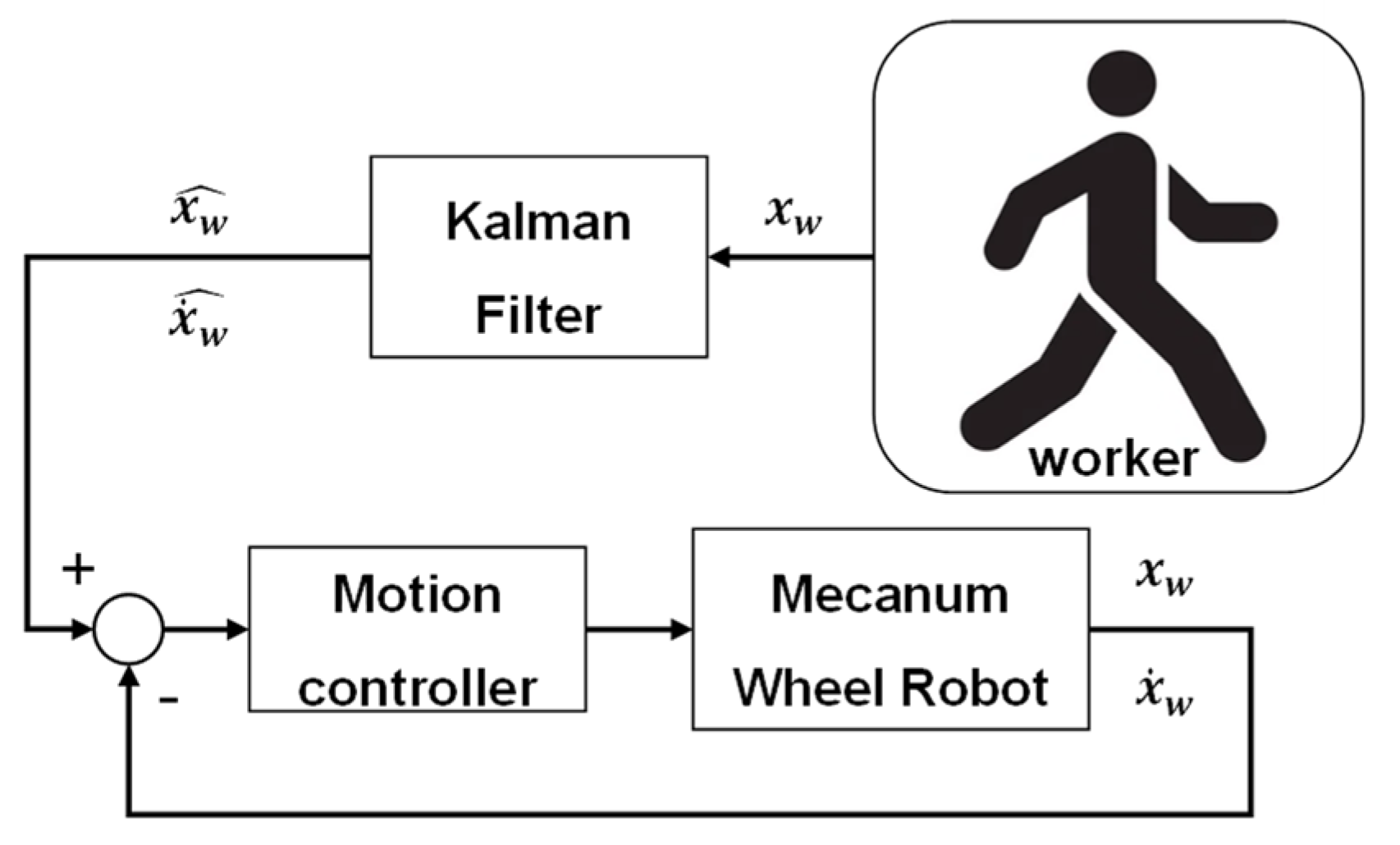
Figure 6 shows the control structure of the proposed Kalman filter-based worker-following robot. From Equations (7) and (8), it can be seen that the data on the position of the worker collected by the image sensor pass through the Kalman filter, and the position and speed of the worker are simultaneously extracted. In the proposed robot control algorithm, the MWR control input is calculated through the comparison of robot tracking results (position and speed).
5. Motion Control of Mecanum Wheel Robot
As shown in Figure 6, the estimated value of the worker’s position, calculated and processed by the Kalman filter, was used as a reference value for the mobile platform to follow the worker. In this study, the worker-tracking performance was improved by simultaneously considering the position and the moving speed calculated and processed by the Kalman filter. Figure 7 shows the control structure of the Mecanum wheel-based mobile robot.
The kinematics for the motion control of a mobile robot is provided as follows [32]:
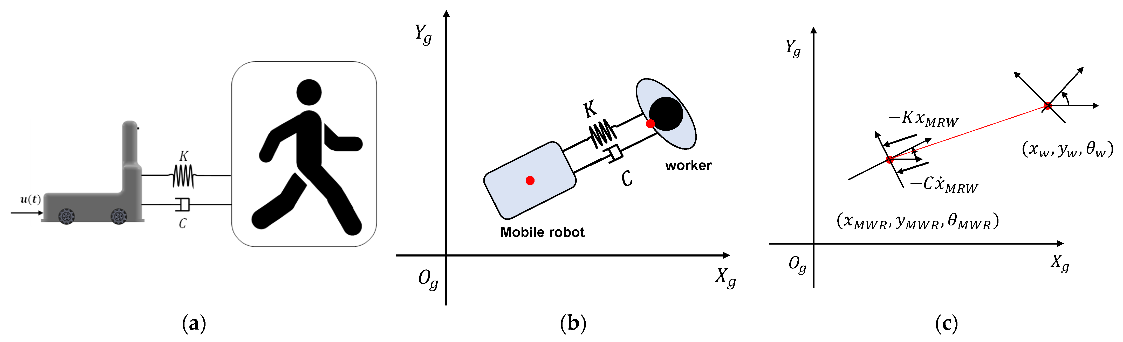
where and represent the linear velocity and angular velocity of the mobile robot, respectively. For the control of the mobile robot, the linear velocity and angular velocity shown in Equations (14)–(16) must be defined. In this study, to define the linear velocity of the mobile robot, it was assumed that both the worker and the mobile platform were a point mass and that a virtual spring and damper existed between the two objects, as shown in Figure 8. Figure 8b,c shows the vertical view of the worker and mobile robot. In Figure 8c, and represent the position of the mobile platform and the worker, respectively. The distance error and speed error were calculated through the error dynamics model for the relative motion of the robot and the worker, as shown in Figure 8:
where the subscript w and MWR represent the worker and MWR, respectively. means the safe distance for preventing collisions between the worker and the robot. The safety distance could be decided according to the production environment. The two main factors to be considered to derive the safety distance are the worker’s moving speed and the road surface friction. If a work site requires high moving speed, a long safety distance will be required. However, in the opposite case, a short safety distance would be required. Another factor to consider in defining safety distance is road friction. In the proposed system, the robot moves along when the worker moves, and the robot stops when the worker stops. In such a system, the stopping distance may be different depending on the friction between the robot and the road surface. When the maximum movement speed of the worker is set as 2 m/s, and the friction of the road surface is 0.5, the braking distance of the robot is calculated to be approximately 0.27 m. If the moving speed of the worker is 0.3 m/s and the road friction is 1.0, the braking distance is calculated as about 0.04 m. Therefore, it is more efficient to set a distance suitable for the worker’s work convenience than to set a safety distance in detail according to the worker’s moving speed and road friction. In this research, we set the safety distance as 0.8 m. The linear velocity and angular velocity of the mobile robot were calculated using the following equation using the induced distance error and velocity error.
where u(t) represents the acceleration of the mobile robot, and K and C, represent the spring constant and damping coefficient, respectively. is the orientation of the worker, and is a positive constant for tuning the angular velocity that represents how fast the robot faces the worker. To define the spring constant (K = 1) and damping coefficient (C = 7), the following cost function was used:
where .
Virtual forces from the spring and damper acted parallel to the line between the robot and the worker, as shown in Figure 8c. The angular velocity was set such that the robot faced the worker. Since the position and speed of the robot for calculating the control input were obtained based on the robot’s odometry and IMU information, and the position and speed of the worker were estimated and processed through the Kalman filter, the relative distance and relative speed between the two objects could be calculated. The controller was designed in such a way that a spring coefficient and a damping coefficient were applied, and an equivalent control input (acceleration) was generated. The linear velocity of the robot was derived through the integration of the induced acceleration input. The error between the target angle and the robot’s angle was used for the angular velocity of the robot, as shown in Equation (25).
6. Simulation Results
Numerical simulations were conducted using Matlab-Simulink to validate the performance of the worker-following robot proposed in this study. As the solver, the fifth order Dormand-Prince formula (ODE5) with a fixed time step (0.01 s) was used. To increase the realism of the simulation, the movement of the worker was created based on the human gait model defined in Section 3 and the measurement error model according to the measured distance of the ArUco marker. The performance of the proposed control method was confirmed by comparing the simulation results of the three control methods for two walking scenarios. The first scenario is designed to test the worker-following performance in the situation of simply following a worker walking in a straight line. This is a situation that occurs most frequently in actual work sites. The second scenario is designed to verify the proposed algorithm-based worker following the performance at a work site assuming an actual assembly line. This is a scenario in which a mobile platform loaded with parts follows a worker and transports necessary parts to each assembly station.
Among the three control methods, the first method was a simulation in which the movement of the worker on the X–Y plane was followed and controlled without Kalman filter-based signal processing. When the worker’s position derived from the gait model passed through the Kalman filter, the position information and speed information that had passed through the filter could be obtained. In the second simulation, the worker was followed based only on the position information, and in the third simulation, the speed of the mobile robot was controlled by simultaneously utilizing the position and speed information of the worker, as suggested in Section 5.
6.1. Straight-Line Walking Scenario
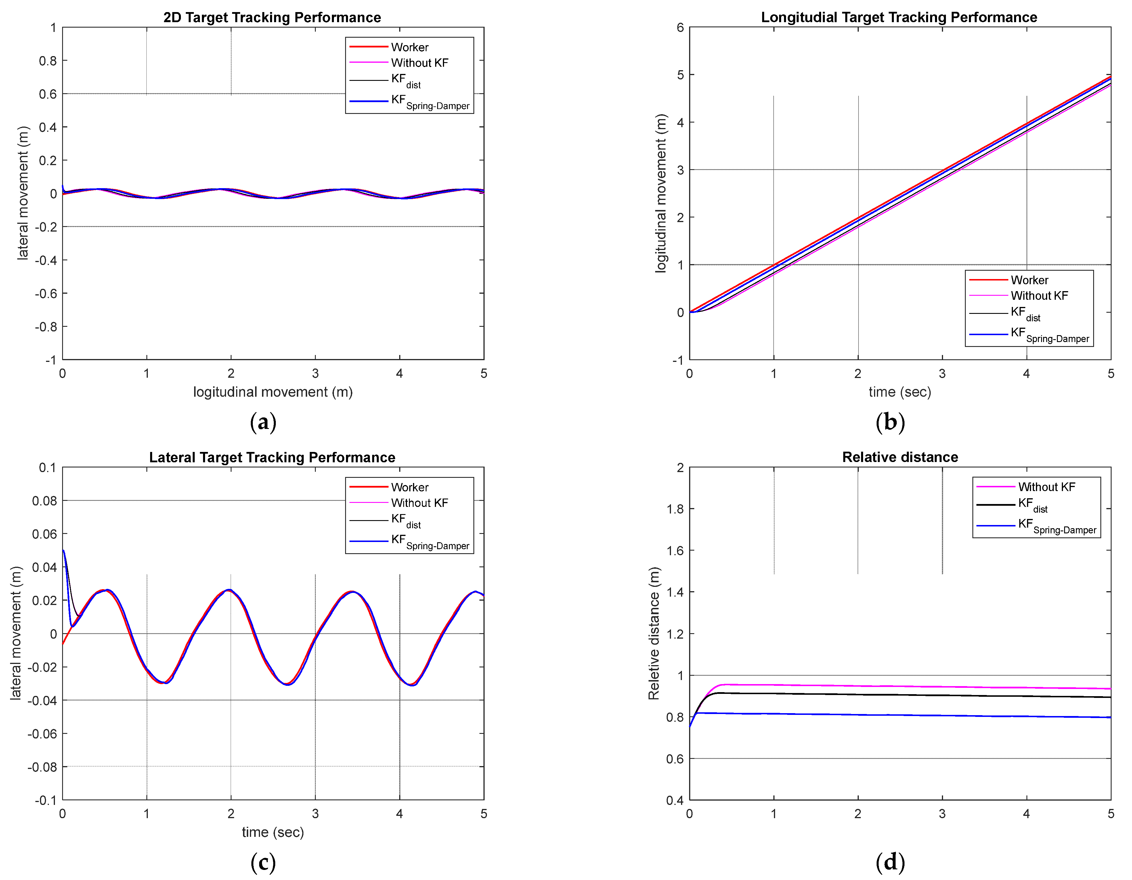
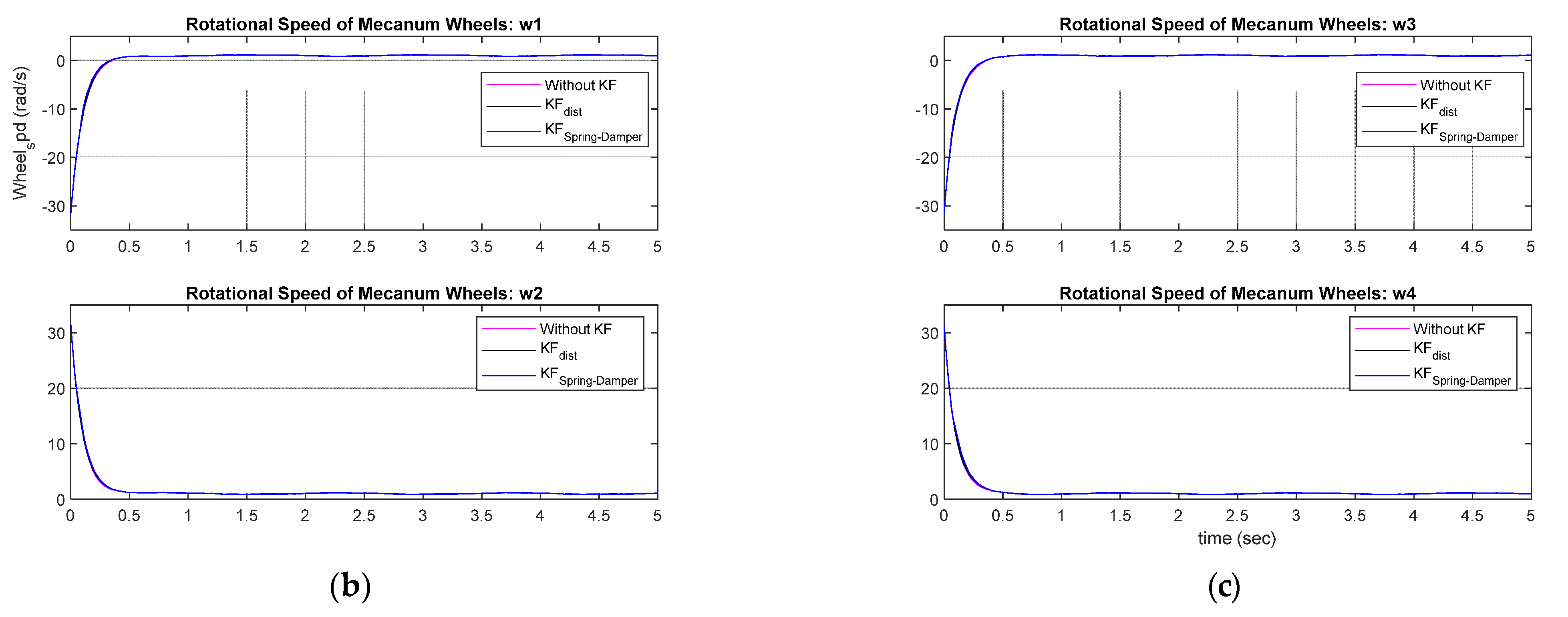
As can be seen from the gait data in Figure 4, the worker moved on a two-dimensional plane, and the movement patterns for the walking direction (X) and the direction perpendicular to the walking direction (Y) were different. Therefore, Kalman filters were designed separately for each coordinate axis. The Kalman filter for the X-axis data was designed as . The Kalman filter for the -axis data was designed as . Figure 9 shows the control performance of the simulation-based worker-following robot in a straight-line walking scenario. In the simulation results, the red line represents the movement of the worker. The case where the Kalman filter was not used is shown in pink, the case where only the distance data among the data obtained through the Kalman filter were used is shown in black, and the method proposed in this study is shown in blue. From the simulation results, it can be confirmed that the proposed method shows better tracking performance than the other methods in X-axis and Y-axis direction tracking. To quantitatively evaluate the performance, the RMSE of the worker following was investigated. For each of the three simulated cases, the RMSE was 0.4569 m, 0.1396 m, and 0.0456 m, confirming that the proposed tracking method exhibits superior performance. Figure 10 shows the longitudinal (advancing direction) velocity and angular velocity, which are the control inputs of the mobile platform.
6.2. Smart Factory Assembly Line Scenario
For a more practical application case for the developed algorithm, a worker-following robot scenario in the assembly line of a smart factory was designed. Figure 11 shows a conceptual diagram of a smart factory introduced in an online article [33] related to smart factories. The environment presented in Figure 11 is a smart factory with complete autonomy. However, this study assumed a work site in which humans and robots collaborated. In other words, the robot’s role was to carry heavy objects while following the worker. For the simulation scenario, it was assumed that a worker moved sequentially from workstation ① to ② to ③. In the case of the existing AGV, the robot moved along the red line in Figure 11b, but in the case of a human, it was assumed that the robot moved along the blue line for the efficiency of the travel path. Accordingly, the robot followed the blue line by following the worker ahead.
For the simulation, the movement path of the worker in the blue line was created through the linear segment parabolic blend (LSPB) method [34,35] as in Appendix A, a trajectory planning method. In addition, the final path was generated by applying the lateral ( direction) movement of the walking model analyzed in Section 3 and the ArUco marker-based position estimation error according to the measurement distance together. Figure 12 shows the vehicle-tracking simulation results for the smart factory scenario. It can be confirmed that all three control methods followed the worker successfully. For the simulation, the same parameters for the Kalman filter were applied as for the straight-line walking simulation. Additionally, the initial position of the robot is defined as . For each control method, the proposed virtual spring damper method produced the lowest RMSEs, showing performances of 1.0446 m, 1.0177 m, and 1.0052 m, respectively.
7. Conclusions
Industrial sites are in a transitional stage of transforming into fully autonomous systems using robotic technology. However, to protect the labor rights and income of field workers, a production system in which humans and robots collaborate is actively applied. This study was developed to increase the work convenience of industrial field logistics workers according to the demands of the industry. In this study, as a key technology for worker-following robots applied to field logistics work, a method for improving the performance deteriorated as the distance between the operator and the image sensor increased accuracy with which the pose of a worker based on an image sensor-ArUco marker is estimated, and a control method for stable worker following are proposed. In the proposed human-following robot system, a worker wears a vest with an ArUco marker printed on it that has a specific ID. Through this system configuration, the mobile robot estimates the position of and tracks the worker. The Kalman filter was applied to improve the position estimation and to enable stable control by assuming a virtual spring and damper between the robot and the worker. The performance of the proposed pose estimation and velocity control method was verified through two simulation scenarios: a straight-line movement scenario and assembly line environment scenario. For both simulation scenarios, the results demonstrate improvements in the human-following performance under the proposed pose estimation and motion control strategy, with a smaller RMSE for the worker-tracking error. However, this study has limitations, as it was based on numerical simulations. To expand the field applicability of the proposed system, we plan to conduct research for the development and improvement of algorithms in the field with the same system configuration based on actual robots in a factory environment.
Author Contributions
Conceptualization, C.K.; methodology, J.S. and K.L.; software, H.Y. and D.K.; validation, H.Y., D.K. and C.K.; formal analysis, J.S. and K.L.; writing—original draft preparation, H.Y., D.K. and C.K.; writing—review and editing, J.S. and K.L.; visualization, H.Y.; supervision, C.K. All authors have read and agreed to the published version of the manuscript.
Funding
This research was supported by Pukyong National University Development Project Research Fund, 2022.
Data Availability Statement
Not applicable.
Conflicts of Interest
The authors declare no conflict of interest.
Appendix A
In this paper, we used LSPB path planning to generate human walking model for the simulation purpose. Figure A1 shows the LSPB-based path planning under given initial and final position, desired velocity, and acceleration. Total trajectory can be divided three segments such as acceleration (segment I), constant speed (segment II), and deceleration (segment III).
Figure A1.
Components of linear segment with parabolic blends (LSPB) Path (a) LSPB total path (b) LSPB shorter path (c) LSPB longer path.
Figure A1.
Components of linear segment with parabolic blends (LSPB) Path (a) LSPB total path (b) LSPB shorter path (c) LSPB longer path.


The corresponding equation are given. In the equations, we defined the longer path coordinate as . If then longer coordinate is y, otherwise longer coordinate is x.
- Segment I (
- Segment II (
- Segment III
References
- Skilton, M.; Hovsepian, F. The 4th Industrial Revolution; Springer: Berlin/Heidelberg, Germany, 2018. [Google Scholar]
- Oyekanlu, E.A.; Smith, A.C.; Thomas, W.P.; Mulroy, G.; Hitesh, D.; Ramsey, M.; Kuhn, D.J.; Mcghinnis, J.D.; Buonavita, S.C.; Looper, N.A. A review of recent advances in automated guided vehicle technologies: Integration challenges and research areas for 5G-based smart manufacturing applications. IEEE Access 2020, 8, 202312–202353. [Google Scholar] [CrossRef]
- Khamis, A.; Meng, J.; Wang, J.; Azar, A.T.; Prestes, E.; Takács, Á.; Rudas, I.J.; Haidegger, T. Robotics and intelligent systems against a pandemic. Acta Polytech. Hung. 2021, 18, 13–35. [Google Scholar] [CrossRef]
- Sung, Y.; Chung, W. Human tracking of a mobile robot with an onboard LRF (Laser Range Finder) using human walking motion analysis. In Proceedings of the 2011 8th International Conference on Ubiquitous Robots and Ambient Intelligence (URAI), Incheon, Republic of Korea, 23–26 November 2011. [Google Scholar]
- Chung, W.; Kim, H.; Yoo, Y.; Moon, C.-B.; Park, J. The detection and following of human legs through inductive approaches for a mobile robot with a single laser range finder. IEEE Trans. Ind. Electron. 2011, 59, 3156–3166. [Google Scholar] [CrossRef]
- Jung, E.-J.; Lee, J.H.; Yi, B.-J.; Park, J.; Noh, S.-T. Development of a laser-range-finder-based human tracking and control algorithm for a marathoner service robot. IEEE/ASME Trans. Mechatron. 2013, 19, 1963–1976. [Google Scholar] [CrossRef]
- Guerrero-Higueras, Á.M.; Álvarez-Aparicio, C.; Calvo Olivera, M.C.; Rodríguez-Lera, F.J.; Fernández-Llamas, C.; Rico, F.M.; Matellán, V. Tracking people in a mobile robot from 2d lidar scans using full convolutional neural networks for security in cluttered environments. Front. Neurorobot. 2019, 12, 85. [Google Scholar] [CrossRef] [PubMed] [Green Version]
- Álvarez-Aparicio, C.; Guerrero-Higueras, Á.M.; Rodríguez-Lera, F.J.; Ginés Clavero, J.; Martín Rico, F.; Matellán, V. People detection and tracking using LIDAR sensors. Robotics 2019, 8, 75. [Google Scholar] [CrossRef] [Green Version]
- Bodor, R.; Jackson, B.; Papanikolopoulos, N. Vision-based human tracking and activity recognition. In Proceedings of the 11th Mediterranean Confernece on Control and Automation, Corfu, Greece, 22–25 June 2003. [Google Scholar]
- Jin, T.-S.; Lee, J.-M.; Hashimoto, H. Position control of mobile robot for human-following in intelligent space with distributed sensors. Int. J. Control Autom. Syst. 2006, 4, 204–216. [Google Scholar]
- Ye, W.; Li, Z.; Yang, C.; Sun, J.; Su, C.-Y.; Lu, R. Vision-based human tracking control of a wheeled inverted pendulum robot. IEEE Trans. Cybern. 2015, 46, 2423–2434. [Google Scholar] [CrossRef] [PubMed]
- Gupta, M.; Kumar, S.; Behera, L.; Subramanian, V.K. A novel vision-based tracking algorithm for a human-following mobile robot. IEEE Trans. Syst. Man Cybern. Syst. 2016, 47, 1415–1427. [Google Scholar] [CrossRef]
- Tsai, T.H.; Yao, C.H. A robust tracking algorithm for a human-following mobile robot. IET Image Process. 2021, 15, 786–796. [Google Scholar] [CrossRef]
- Hoshino, F.; Morioka, K. Human following robot based on control of particle distribution with integrated range sensors. In Proceedings of the 2011 IEEE/SICE International Symposium on System Integration (SII), Kyoto, Japan, 20–22 December 2011. [Google Scholar]
- Kobilarov, M.; Sukhatme, G.; Hyams, J.; Batavia, P. People tracking and following with mobile robot using an omnidirectional camera and a laser. In Proceedings of the 2006 IEEE International Conference on Robotics and Automation, Orlando, FL, USA, 15–19 May 2006. [Google Scholar]
- Luo, R.C.; Chang, N.-W.; Lin, S.-C.; Wu, S.-C. Human tracking and following using sensor fusion approach for mobile assistive companion robot. In Proceedings of the 2009 35th Annual Conference of IEEE Industrial Electronics, Porto, Portugal, 3–5 November 2009. [Google Scholar]
- Zender, H.; Jensfelt, P.; Kruijff, G.-J.M. Human-and situation-aware people following. In Proceedings of the RO-MAN 2007-The 16th IEEE International Symposium on Robot and Human Interactive Communication, Jeju Island, Republic of Korea, 26–29 August 2007. [Google Scholar]
- Susperregi, L.; Martínez-Otzeta, J.M.; Ansuategui, A.; Ibarguren, A.; Sierra, B. RGB-D, laser and thermal sensor fusion for people following in a mobile robot. Int. J. Adv. Robot. Syst. 2013, 10, 271. [Google Scholar] [CrossRef]
- Shashank, M.S.; Saikrishna, P.; Acharya, G.P.; Reddy, S.; Lavanya, P. Design and Development of Human Following Autonomous Airport Baggage Transportation System. In Proceedings of the 2022 International Conference on Advances in Computing, Communication and Applied Informatics (ACCAI), Chennai, India, 28–29 January 2022. [Google Scholar]
- Shan, M.; Zou, Y.; Guan, M.; Wen, C.; Ng, C.-L. A leader-following approach based on probabilistic trajectory estimation and virtual train model. In Proceedings of the 2017 IEEE 20th International Conference on Intelligent Transportation Systems (ITSC), Yokohama, Japan, 16–19 October 2017. [Google Scholar]
- Tsun, M.T.K.; Lau, B.T.; Jo, H.S. Exploring the performance of a sensor-fusion-based navigation system for human following companion robots. Int. J. Mech. Eng. Robot. Res. 2018, 7, 590–598. [Google Scholar] [CrossRef]
- Che, Y.; Culbertson, H.; Tang, C.-W.; Aich, S.; Okamura, A.M. Facilitating human-mobile robot communication via haptic feedback and gesture teleoperation. ACM Trans. Hum. Robot. Interact. (THRI) 2018, 7, 1–23. [Google Scholar] [CrossRef] [Green Version]
- Kyzer, T. Instrumentation and Experimentation Development for Robotic Systems. Ph.D. Thesis, University of South Carolina, Columbia, SC, USA, 2021. [Google Scholar]
- Filus, K.; Sobczak, Ł.; Domańska, J.; Domański, A.; Cupek, R. Real-time testing of vision-based systems for AGVs with ArUco markers. In Proceedings of the 2022 IEEE International Conference on Big Data (Big Data), Atlanta, GA, USA, 17–20 December 2022. [Google Scholar]
- Doroftei, I.; Grosu, V.; Spinu, V. Omnidirectional Mobile Robot-Design and Implementation; INTECH Open Access Publisher: London, UK, 2007. [Google Scholar]
- Maulana, E.; Muslim, M.A.; Hendrayawan, V. Inverse kinematic implementation of four-wheels mecanum drive mobile robot using stepper motors. In Proceedings of the 2015 international seminar on intelligent technology and its applications (ISITIA), Surabaya, Indonesia, 20–21 May 2015. [Google Scholar]
- Taheri, H.; Qiao, B.; Ghaeminezhad, N. Kinematic model of a four mecanum wheeled mobile robot. Int. J. Comput. Appl. 2015, 113, 6–9. [Google Scholar] [CrossRef]
- Li, Y.; Dai, S.; Zheng, Y.; Tian, F.; Yan, X. Modeling and kinematics simulation of a Mecanum wheel platform in RecurDyn. J. Robot. 2018, 2018, 9373580. [Google Scholar] [CrossRef]
- Schreiber, C.; Moissenet, F. A multimodal dataset of human gait at different walking speeds established on injury-free adult participants. Sci. Data 2019, 6, 111. [Google Scholar] [CrossRef] [PubMed] [Green Version]
- Kalaitzakis, M.; Carroll, S.; Ambrosi, A.; Whitehead, C.; Vitzilaios, N. Experimental comparison of fiducial markers for pose estimation. In Proceedings of the 2020 International Conference on Unmanned Aircraft Systems (ICUAS), Athens, Greece, 1–4 September 2020. [Google Scholar]
- Welch, G.; Bishop, G. An introduction to the kalman filter. Proc. SIGGRAPH Course 2001, 8, 41. [Google Scholar]
- Siegwart, R.; Nourbakhsh, I.R.; Scaramuzza, D. Introduction to Autonomous Mobile Robots; MIT Press: Cambridge, MA, USA, 2011. [Google Scholar]
- Choi, K. ADLINK and Intel Release Robot Controller ‘Roscube-I’ for Innovative ‘Edge AI Robot’. Available online: https://www.aitimes.kr/news/articleView.html?idxno=16652 (accessed on 24 January 2023).
- Rodd, M.G. Introduction to robotics: Mechanics and control. In Pergamon; PEARSON Prentice Hall: Hoboken, NJ, USA, 1987. [Google Scholar]
- Siciliano, B.; Sciavicco, L.; Villani, L.; Oriolo, G. Motion Planning. In Robotics: Modelling, Planning and Control; MIT Press: Cambridge, MA, USA, 2009; pp. 523–559. [Google Scholar]
Figure 1.
Fiducial marker-based worker-following control system.

Figure 2.
Coordinate systems for a Mecanum wheel-based mobile robot platform.

Figure 3.
Position estimation error with relative distance: mean and standard deviation: (a) without shadow; (b) with shadow.
Figure 3.
Position estimation error with relative distance: mean and standard deviation: (a) without shadow; (b) with shadow.

Figure 4.
Marker set for collecting human gait data [29].
Figure 4.
Marker set for collecting human gait data [29].

Figure 5.
Analysis of marker movement according to straight walking: (a) X–Z directional movement; (b) X–Y directional movement; (c) Y–Z directional movement.
Figure 5.
Analysis of marker movement according to straight walking: (a) X–Z directional movement; (b) X–Y directional movement; (c) Y–Z directional movement.

Figure 6.
The control structure of a worker-following robot.

Figure 7.
A Simulink model of the worker-following robot controller.

Figure 8.
Relative motion of the worker and mobile robot. (a) Lateral view; (b) Vertical view; (c) Vertical view (point mass).
Figure 8.
Relative motion of the worker and mobile robot. (a) Lateral view; (b) Vertical view; (c) Vertical view (point mass).

Figure 9.
Worker-following performance: (a) 2D plane worker-following performance; (b) Longitudinal direction performance; (c) Lateral direction performance; (d) Target-tracking performance (relative distance).
Figure 9.
Worker-following performance: (a) 2D plane worker-following performance; (b) Longitudinal direction performance; (c) Lateral direction performance; (d) Target-tracking performance (relative distance).

Figure 10.
Control inputs for the MWR: (a) Linear and angular speed of the robot (b,c); Rotational speed of Mecanum wheel motor.
Figure 10.
Control inputs for the MWR: (a) Linear and angular speed of the robot (b,c); Rotational speed of Mecanum wheel motor.


Figure 11.
Control inputs for the MWR: (a) Linear and angular speed of the robot; (b) Rotational speed of Mecanum wheel motor.
Figure 11.
Control inputs for the MWR: (a) Linear and angular speed of the robot; (b) Rotational speed of Mecanum wheel motor.

Figure 12.
Worker-following performance: (a) 2D plane worker-following performance (b) Longitudinal direction performance (c) Lateral direction performance (d) Target tracking performance (relative distance).
Figure 12.
Worker-following performance: (a) 2D plane worker-following performance (b) Longitudinal direction performance (c) Lateral direction performance (d) Target tracking performance (relative distance).


Table 1.
ArUco marker pose estimation error (Logitech C270 Webcam) [30].
Table 1.
ArUco marker pose estimation error (Logitech C270 Webcam) [30].
| Distance (cm) | Without Shadow | With Shadow | ||||
|---|---|---|---|---|---|---|
| Mean (%) | Standard Deviation | Success Rate (%) | Mean (%) | Standard Deviation | Success Rate (%) | |
| 75 | 2.067 | 0.021 | 97.07 | 2.034 | 0.027 | 95.98 |
| 100 | 2.204 | 0.028 | 95.94 | 2.184 | 0.028 | 96.03 |
| 150 | 2.242 | 0.112 | 96.18 | 2.443 | 0.315 | 96.07 |
| 175 | 2.315 | 0.229 | 96.10 | 2.620 | 0.197 | 95.99 |
| 200 | 3.050 | 0.315 | 96.08 | 3.615 | 0.200 | 96.47 |
Disclaimer/Publisher’s Note: The statements, opinions and data contained in all publications are solely those of the individual author(s) and contributor(s) and not of MDPI and/or the editor(s). MDPI and/or the editor(s) disclaim responsibility for any injury to people or property resulting from any ideas, methods, instructions or products referred to in the content. |
© 2023 by the authors. Licensee MDPI, Basel, Switzerland. This article is an open access article distributed under the terms and conditions of the Creative Commons Attribution (CC BY) license (https://creativecommons.org/licenses/by/4.0/).
Share and Cite
MDPI and ACS Style
Yoo, H.; Kim, D.; Sohn, J.; Lee, K.; Kim, C. Development of a Worker-Following Robot System: Worker Position Estimation and Motion Control under Measurement Uncertainty. Machines 2023, 11, 366. https://doi.org/10.3390/machines11030366
AMA Style
Yoo H, Kim D, Sohn J, Lee K, Kim C. Development of a Worker-Following Robot System: Worker Position Estimation and Motion Control under Measurement Uncertainty. Machines. 2023; 11(3):366. https://doi.org/10.3390/machines11030366
Chicago/Turabian StyleYoo, Hyeongrok, Dohyun Kim, Jeonghyun Sohn, Kyungchang Lee, and Changwon Kim. 2023. "Development of a Worker-Following Robot System: Worker Position Estimation and Motion Control under Measurement Uncertainty" Machines 11, no. 3: 366. https://doi.org/10.3390/machines11030366
Note that from the first issue of 2016, this journal uses article numbers instead of page numbers. See further details here.