
Mechanical Design and Performance Analysis of a Weevil-Inspired Jumping Mechanism


College of Mechanical and Electrical Engineering, Nanjing University of Aeronautics and Astronautics, Nanjing 210016, China
*
Author to whom correspondence should be addressed.
Machines 2022, 10(3), 161; https://doi.org/10.3390/machines10030161
Submission received: 13 January 2022
/
Revised: 4 February 2022
/
Accepted: 9 February 2022
/
Published: 22 February 2022
(This article belongs to the Special Issue Bio-Inspired Smart Machines: Structure, Mechanisms and Applications)
Abstract
:Jumping mechanisms constitute an important means of resolution in applications such as crossing uneven terrain and space exploration. However, the traditional design mainly uses engineering design thinking, but seldom studies the structural characteristics of organisms themselves and lacks biomimetic research basis, which leads to the difference between jumping mechanism and biological structure and its jumping ability. On the other hand, it lacks in-depth study on biological jumping mechanism from the view of engineering. Weevil has excellent jumping performance, and its key jumper structure is specially designed by biologist. To investigate the motion mechanism and working mechanism of the jumping mechanisms, this paper takes the weevil as the bionic object, and designs a weevil-inspired jumping mechanism. A miniature prototype is designed to reproduce weevil’s jumping mechanism with its working principle and anatomical structure to verify how weevil’s jumping mechanisms work, and turns out to perform well at jumping height. This paper is presented the anatomical structure and working principle of the weevil jumping mechanism, followed by explanation and analysis of its kinematics and dynamics, then performing virtual prototype simulations to compare different design schemes, with results guiding the parameter optimization and subjecting a prototype machine into a height test. In comparisons among existing jumping mechanisms whose jumping method is bio-inspired, the present design, which weighs 44.7 g and can jump to a maximum height of 2 m. The present research establishes a biologically inspired working principle and provides a new practical archetype in biologically inspired studies.
1. Introduction
Overcoming obstacles and rough terrain is a difficult but common challenge faced by miniature jumping robots. In general, biological creatures do so by flying, climbing, or jumping, of which jumping is superior in that it (i) uses less energy and is quieter than flying and (ii) is simpler and more reliable than climbing. The decisive factor for a mechanism’s jumping performance is its mechanical design, and there has been much research into methods for storing and releasing energy. In those works, some structures such as planar six-bar mechanism and cams have emerged as being particularly useful and have been used widely.
Among them, the planar six-bar mechanism is the structure that is used most widely. A typical planar six-bar mechanism comprises bars in a hexagonal configuration that has mirror symmetry both vertically and horizontally. However, the upper and lower edges of the hexagon are usually realized in the form of joints or planes, and linear tension elements are usually fixed on their left and right endpoints. Anderson learned through research that elastic energy storage and utilization can enhance jumping efficiency much more than overall jumping performance [1,2]. So it is useful to increase the jumping range with energy storing strategies by adding springs. To maximize the stored energy, springs usually appear in parallel; they store energy by widening the structure while compressing its height and lowering its center of mass (COM). This design is the most universal and the one most likely to achieve high energy destiny. Jung used it in their JumpROACH and its previous type [3,4], and Woodward used it in their Multimo-Bat [5]. Because of its good performance, this classical design has been altered variously to adapt it to more requirements. In their wheeled mechanism, Ye converted the linear rods into arcs to allow the wheels to rotate [6]. In their Jump-Flapper, Truong broke the linear springs into two disconnected ones and changed their hanging locations [7]. In their MSU Jumpers, Zhao removed the linear springs and instead used torsion ones on the joints to gain space inside the hexagon [8,9,10].
Cams are used widely as triggering solutions. A cam stores energy as its radius increases and then releases that energy freely when its radius jumps from maximum to minimum. As such, the two degrees of freedom (DOFs) of storing energy and triggering are combined into one using only one component, and therefore cams are very suitable for robots for which the main priority is to minimize the weight. In their work, Shen, Zhang and Kovac used cams for triggering [11,12,13].
Another way to design a mechanism that has superior jumping ability is to use biologically inspired design. Because many insects can jump to heights of tens or even hundreds of times their body length, potential designs can come from studying their jumping locomotion or anatomical structure. However, most bio-inspired jumping mechanisms to date have been designed by focusing on limb locomotion, the aim being to maximize the jumping height by enlarging the gain in displacement during launch. Feature points extracted using high-speed photography are recombined into the skeleton of the mechanism. Typical examples are (i) the galago-inspired SALTO series by Haldane and (ii) numerous flea- and locust-inspired robots, such as that proposed by Zhang [14,15,16,17,18,19]. Rarer in the literature is bio-inspired design based on an anatomical launching principle, even though such an approach is essential for improving how energy is stored and released [17]. Of this type exists the flea-inspired robot developed by Noh [20,21,22].
According to Nadein, weevils (Coleoptera: Curculionidae: Rhamphini) can reach a maximum speed of 2.0 m/s when jumping, which is quite large among jumping insects. With their hind legs being relatively short, their jumping ability is attributed instead mainly to their special jumping mechanism [22].
However, this special structure is yet to be realized into an engineering design. To fill in this research gap, we have designed a jumping mechanism according to the anatomical structure of weevils and involving no classical structures. With few but useful improvements to achieve better engineering performance, it well explains jumping principle of a weevil’s jumping mechanism. It represents a new structure type in the research into bio-inspired jumping mechanisms, and shows feasibility and superiority of this structure by operating smoothly and performing well in jumping height.
In this study, with weevil’s jumping mechanism as the research object, designs a weevil-inspired jumping mechanism, its kinematic and dynamics were explanted and analyzed, virtual prototype simulation and experiment were then conducted. This study provides a new practical archetype in biologically inspired studies.
2. Design of Jumping Mechanism
We present a new jumping mechanism with the bionic idea from weevil, and it is not like the existing jumping mechanism.
2.1. Biological Working Principle
With limbs that are relatively short, the weevil’s jumping ability comes mainly from its jumping mechanism. From anatomical observations, Nadein proposed a functional model of the weevil’s jumping mechanism [22].
In the initial phase, the extensor muscle is relaxed, and contraction of the flexor muscle (fm) minimizes the angle between the femur and tibia until the flexion state, to restore the jumping mechanism. During this period, the tibial flexor sclerite (TFS) is dragged over an internal protrusion (ip) (Figure 1a,b).
Next, the extensor muscle begins to contract, pulling the metafemoral extensor tendon (MET) to store energy by stretching the extensor ligament (el). The fm is now kept contracted so as not to displace the TFS (Figure 1b,c).
When the energy stored in the el reaches a certain amount, the fm is relaxed. This causes the TFS to be dragged over the internal protrusion again to the lower side. Losing the pull provided by the fl, the tibia rotates freely around the pivot, driven by the huge extension force provided by the el (Figure 1c,d). As the tibia rotates relative to the femur, the body of the weevil is sent into the air.
Because of the support from the ip to the tibial flexor sclerite in the configuration shown in Figure 1c, a relatively small force is required to stop the tibia from rotating. Compared to structures with no sclerite or internal protrusion, the weevil’s jumping mechanism requires less power in the fm.
2.2. Mechanical Redesign
Based on the working principle of the weevil’s jumping mechanism and aimed at better engineering implementation, the jumping mechanism is redesigned into a mechanical structure. In our design, the pull from the flexor muscle is removed through a mechanical position-limiting design. Representing the tibial flexor sclerite, a triangular slider (TS) is driven by rectangular slider (RS) through the upper string (US), and the RS is driven by the motor, thereby saving a degree of freedom.
This design can be approximated as a two-dimensional model as shown in Figure 2, where the parts are named. The shell of the femur becomes the Support board (SB), which contains structures including the guide rail of the RS, the sliding bolt-nut pair (NBP), the string hole, and the protrusion structure (PS). The latter corresponds to the internal protrusion in the biological jumping mechanism. The biotical TFS becomes the TS mechanical structure. The slider is designed to move downward freely in its guide rail beneath the PS, and go through the gap between the RS and the PS. While above the PS, it is also being credible to touch the PS at its cup while strings are tensioned.
The metafemoral extensor tendon becomes the RS. Inside this is a nut that is driven by the motor so that the RS moves in a straight line along the output shaft, driving the RS to move together with it on its guide rail.
The tibia becomes the pole, which was not designed precisely. It is connected to the SB with a revolute joint, enabling it to rotate freely around the joint. Hollow structures are designed so that the pole does not interfere with the SB. The guide rail of the lower string (LS) is to the right of the joint, and springs hang on the other side.
The scalar design is arranged to match the length of the motor output shaft (MOS) in scale, and detailed shape design to fit the angular range of output movement with the one of biological mechanism, also to enlighten the mechanism as much as possible. Besides, the length of the pole is decided according to a rule described in Section 3.2 to maximize the jumping height.
2.3. Working Cycle
Figure 3 shows the working cycle of the mechanism. The springs are loaded for a relatively long time, during which a large amount of elastic energy is stored. Soon after, it is released in a moment so that the pole is driven freely by the springs, transforming the stored energy into kinetic energy. Throughout the whole cycle, the springs always have a preload.
Between the stages shown in Figure 3a,b, the RS moves downwards and pulls the TS moving upwards through the US. Size of the PS, TS and RS are adjusted carefully to let the TS get through the gap between the RS and PS smoothly.
Between the stages shown in Figure 3b,c, the RS moves upward and the two strings are both tensioned. The TS moves downward from its highest position until it reaches the L-shaped PS, whereupon it rotates because of the unbalanced torque until it comes into contact with the sliding nut–bolt pair. Now, the tension in the lower string and the support from the sliding nut–bolt pair and the protrusion structure form a balance in the TS, stopping it from displacing. Also, the pole is unable to rotate because of the pull provided by the LS.
Between the stages shown in Figure 3c,d, the RS continues to move upward, pushing the NBP upward in its guide rail and taking the place of the NBP in the position limit of the TS.
These two processes, in which the RS moves upward, stretching the springs while the pole stays locked in the pre-triggering stage, reflect the processes in the biological jumping mechanism whereby the flexor muscle holds the tibia and the tensed extensor muscle stretches the extensor ligament, storing elastic energy therein.
Between the stages shown in Figure 3d,e, the RS continues to move upward. At a critical position, it loses contact with the TS, whereupon the position limit for the TS is lost. The TS then falls freely down through its guide rail. During this sliding action, the lower string slides to the other end of its guide rail on the pole. This is the launching process, whereby the pole is driven violently by the springs releasing their elastic energy in a moment.
The corresponding process in the biological structure is when the fm relaxes and the TFS loses the forces that were stopping it from moving toward the tibia, whereupon the tibia is driven by the el to rotate with great acceleration.
After the stage shown in Figure 3d, the RS continues to move upward until its upper limit, whereupon the motor rotates in the opposite direction, sending the sliders to their opposite ends and restoring the stage shown in Figure 3a. During this period, the lower string slides to the end farthest from the revolute joint, and the sliding nut–bolt pair slides to the lower end. This is the resetting process that marks the end of the cycle.
To describe how the movements of the RS, TS, and pole are related, the whole mechanism is simplified into a geometrical model as shown in Figure 4. The origin of the coordinate system is dot O, the revolute joint connecting the SB and the pole. The y axis is parallel to the motor output shaft, and the x axis is vertical. The string hole and the TS become a dot to simplify the whole model. The variables appear in the form ; for example, is the distance between dots O and P. The value of such a variable is calculated using the Pythagorean method and the coordinates of each dot.
The variable η is defined to express the displacement of the TS on its orbit, the line UO, through the constraint in the upper string. The value of η is calculated as
In the triangle formed by points T, O and P, we have
As reaches a critical value at which the lower string is almost perpendicular to the direction, the lower string slides from its present end to the other. We call this critical angle . Therefore, jumps occur in and , leading to the jump in the curve of versus shown in Figure 5. The maximum and minimum values of are 146° and 26°, respectively, very close to those in the biological structure, namely 141° and 24°, respectively [22].
2.4. Theoretical Dynamical Analysis
Komarsofla has proposed a novel one-legged hopping robot mechanism with aflat foot [23]. By researched the transitions between different modes and the conditions for these transitions, including stance, taking-off under-actuated, flight, landing under-actuated, and recovery, they derived the potential and kinetic energies of the system and other terms of the Euler–Lagrange equations. On this basis, we established the dynamic equation. Adopting the same coordinates as those in Figure 4 (O as the origin; the motor output shaft as the y axis), the mechanism is abstracted into a simpler model for dynamical analysis of the ejection process as shown in Figure 6.
The mass of the whole mechanism excluding the pole is . The COM of this part is marked with the bigger black-and-white icon, and distance from it to point O is . The distances from point O to the two ends of the pole are and , and that to the COM of the pole is . The mass of the pole is , with its COM on the smaller black-and-white icon. The angle between the horizontal plane and the pole is , and that between the pole and line OM is .
Lagrange dynamical equations are set up to carry out dynamical analyses. Here refers to values of torques on the point where the pole contacts with the ground, and refers to torque on the point O.
The dynamic equation of the mechanism can be written in the form:
where is the 2 × 2 mass matrix of the mechanism, is the Coriolis coefficients, is an 2 × 2 matrix of centrifugal coefficients. is an 2 × 1 vector of gravity terms. Therefore, we have
Other dynamical indicators that describe the motion during the ejection process are given in Equations (14)–(16) and are plotted in Figure 7. The angle between the springs and the pole is
The torque on point O applied by the springs is
The tension in the lower string is
Based on the model roughly designed through kinematics analyses, a virtual prototype is built in detail to study how some dynamical paraments of this mechanism vary via time. The result shows that angular kinetic energy is ignorable relative to translational kinetic energy, so that little energy loss is caused by spinning.
3. Virtual Prototype Simulation
3.1. Introduction to Simulation
With kinematics analysis above and to fit the size of motor output shaft and range of the angle between tibia and femur during a weevil’s jump, we have arrived at an abstract structural design. To have precise adjustments on some parameters having considerable impact on jumping ability of the mechanisms, we carried out virtual prototype simulations to learn about how these parameters impact with jumping orbit of the mechanism.
Some virtual prototypes with differences in certain variables are built and tested in the MSC Adams software package (version 2018). The simulation results were imported and processed in the MATLAB software package (version R2019a) and then plotted to determine how to improve the performance of the mechanism by controlling these variables.
A typical virtual prototype is built according to the parameters defined in Figure 8. The scale is defined to match the length of the MOS. is set to 73 mm, to 5.5°, to 84 mm, to 5.2°, to 2.3 mm, to 30 mm, to 45 mm, to 73 mm, and to 0.64 N/mm. Here, is the stiffness coefficient of the springs, and is the angle between the motor output shaft and the horizontal plane. The value of the latter just before ejection is defined to be and is 26.2° here.
3.2. Spepated Variable Simulation
In this section, the parameters , , and are altered in turn to see how they influence the performance of this mechanism. Only one or two variables are adjusted simultaneously. After altering each variable separately, and are adjusted together while keeping the COM right above the front end of the pole. Ding have mentioned that horizontal off-set between the COM and the contacting point during the launch leads to horizontal displacement of the flight [24]. This cross-variable-comparison is proposed in supplementary to test how can we maximize its jumping height while setting the similar limit to the horizontal displacement. Unless stated otherwise, a variable takes its value from the original prototype. Table 1 shows the featured dynamical parameters that can reflect the jumping performance of the jumping mechanism. Figure 9 shows how these variables impact on the jumping performance.
In Figure 9a, is changed to analyze how it influences the chosen indicators of ejection performance. In the physical prototype, this variable can be changed by changing the number of springs or using springs with different stiffness.
In Figure 9b, is changed by modifying the length of the thin slice attached to the end of the pole in the direction in which the pole is pointing. This operation hardly changes the mass distribution. When is set as 71 mm, the mechanism starts turning over before ejection because the projection of the COM on the ground is outside the supported area; in this case, the device slips upon ejection. By setting as 72 mm or larger, the device stands in a stable manner.
In Figure 9c, is changed such that is 26.5°, 30.3°, 33.5°, 36.4°, and 39.1°. With set to 44 mm, the mechanism falls so quickly that the ejection is considered to fail.
In Figure 9d, because 43 mm is the minimum value for the whole running cycle to finish (otherwise the TS would be unable to form the position limit), is assigned starting with 44 mm, so is correspondingly 21.8°, 26.5°, 30.3°, 33.5°, and 36.4°. Meanwhile, is set as a function of , with the constraint condition provided by kinetic analyses, aiming at keeping the projection of the COM on the ground near the front edge of the pole. Here, the best value is to be determined.
Each comparison shown in Figure 9 is analyzed below in order. With increasing , the jumping performance of the mechanism grows almost linearly. However, the internal reaction forces also grow, thereby drawing more motor power.
The value of has little effect on how the components interact with each other, but it has a large effect on the ejection orbit. A critical value Lc appears when the projection of the COM on the ground coincides with the front edge of the box on the pole. With greater than , the height performance worsens slowly, the landing position moves in the −x direction, and the angular velocity increases slowly. With less than , slips occur that lead to ejection failure, and consequently the jumping height decreases sharply. Therefore, the value of should be set so that the projection of the COM on the ground is close to the front edge and securely inside the supported area.
Keeping steady but decreasing in the range that enables the operation cycle to finish, the maximum elastic energy is stored, thereby leading to greater displacement and forces being produced, as well as faster spinning. is expected to be smaller, but a sufficient margin is required to avoid the risk of turning over caused by uneven terrain and vibrations while the mechanism is running. For the case shown in Figure 8, suitable values are 44 mm for and 30° for .
For cases in which the COM is right above the front edge of the pole, because torque applied to the COM is reduced by minimizing arms of forces causing spinning, the rotations are reduced adequately.
In conclusion, a larger value should be adopted to maximize the force used for launching, should be controlled as a function of to keep the subpoint of the COM near the front edge of the pole. In the meantime, should be kept as short as possible to lower the COM before the launch, releasing more energy during the ejection.
3.3. Dynamical Quantities vs. Time
To observe the instantaneous status of the mechanism, some parameters were sampled during the ejections of two chosen virtual prototypes. These cases have the same geometrical design but with values of 0.64 and 1.28 N/mm, the latter being used for the physical prototype. To plot smooth curves of these parameters versus time, the data were over-sampled and filtered by a moving-average filter at a length of nine. Figure 10 shows the time-varying trends during ejection and while in the air.
The curves in Figure 10 show that the ejection starts at 0.4 s and lasts for a very short while. In a short period before and after the ejection, for the two different values adopted, the chosen parameters have the same trend. With bigger value adopted, the curve grows linearly, and time spent in the ejection declines.
The maximum horizontal and vertical displacements grow in the same ratio as is doubled. The tension in the springs is established as the RS moves upward and is then released rapidly at the ejection. increases rapidly during the ejection but is constant before and after this process.
The tension in the upper string is small before the ejection, and a pulse for accelerating the TS appears during the ejection. This pulse can be weakened by lengthening the upper string, to transfer this force into collision between the TS and SB. The lower string is tensioned before the ejection and released at the ejection. If is set too short, then a pulse can appear at the ejection to stop the pole.
The spinning accelerates swiftly then decelerates markedly because of the separate actions for each part during ejection of the pole. This spinning then decelerates slowly during the in-air process.
To have a jump that is gentle in damage but strong in displacement, a larger value of should be set, the surfaces of the sliders should be polished to reduce friction, and the strings must be long enough to avoid inducing intense interior pulse forces.
4. Experimental Studies
4.1. Introduction
Based on the chosen scheme of virtual prototype, a physical prototype (Figure 11) was built using three-dimensional printing. Fishing wire was used for the upper and lower strings, and the total stiffness of the serried springs was measured to be 1.28 N/mm. The motor adopted is in the GA12-N20 type, with an output shaft in the length of 55 mm. The Li-ion battery is with an output voltage of 12 V.
To deal with uneven terrain and vibration of the motor while running, a PVC slice was attached to the pole through nut–bolt pairs, thereby enlarging the supported area and preventing the mechanism from falling over. Being convenient to install and uninstall, we used it as our method for adjusting the variable .
4.2. Orbit Test
We subjected the mechanism to an ejection test to verify its jumping performance. In the recording, a scale in centimeters was set as the background. Because of installation error, according to the first frame in Figure 12 for t = 0 ms, the height of the COM seemed to be approximately −7 cm. For normalization, we added 12 cm to all the sampled height data. The recording was done using a camera with a frame rate of 480 frames per second; frames during the in-air process were sampled uniformly and are arrayed in Figure 12 The time cost of the catapult action is estimated as being 12.5 ms, which is six times that in the biological structure, namely 2.1 ms [22].
The vertical displacement of the COM during a typical jump was sampled uniformly and is plotted in Figure 13 as the blue dots fitted with the red parabola in MATLAB (version R2019a) through a polynomial model with a degree of two. And height-to-time curves of other jumps distributes in the area surrounded by imaginary curves and colored with pink.
The height of the COM was 5 cm before the ejection and reached approximately 205 cm at apex. Thus, the maximum vertical displacement that was achieved is 200 cm, which corresponds to an increase in potential energy of 0.876 J.
Compared with the simulation results, the experimental jumping height is smaller than the simulation results, because the actual test needs to consider friction or other objective conditions, this can be seen from the comparison between the red line peak value of k = 1.28 in Figure 10a and the experimental jump height in Figure 12 and Figure 13. The overall results are consistent, and the superior performance of the jumping mechanism is verified by simulation and experiment.
5. Discussion
Two topics are to be discussed in this section. The first one is comparisons in similarity of the corresponding biological structure, followed by comparisons in novelty of adopted elements. The second one is statements on measurements of proposed mechanism, followed by comparisons in jumping height performances. Each comparisons are carried out between this work and other miniature jumping mechanisms.
This work is introducing few structures that does not exist in biological structures, and all of them plays an auxiliary role in the working principle (namely the NBP), or being unavoidable in recent researches (namely motor and its relevant elements). Except for this work, few can do the same. The flea-inspired mechanism TAUB [25,26], as a miniature mechanism that is bio-inspired in jumping method which performs the best in jumping altitude according to our survey, uses a hook as its triggering method, BounceBot operates in a similar way [27]. However, no corresponding structure exists in a flea’s jumping mechanism. Even the mechanism well explains working principle of a flea’s jumping mechanism propose by Koh is adopting planar six-bar mechanism to provide the leaping force [21].
Most of resent bio-inspired works focus on limb locomotion during an insect’s jump, and the biological archetype adopted are usually fleas or locusts. Ones using traditional mechanical design methods can hardly avoid using planar six-bar mechanism or other more complex linkage structure [28]. Therefore, new mechanical structure and archetypes introduced at present can promote researches on jumping mechanisms. Inspired by weevils, a kind of insect nobody has built a jumping mechanism according to, a new strategy for storing and releasing energy was enabled herein, providing a new type of structure for miniature jumping robots. Unlike most bio-inspired miniature jumping mechanisms focused on increasing the gain of displacement output by imitating the external appearance of the creature concerned, our work has proposed a new strategy for storing and releasing energy, one that is rarely seen but that has the potential to be combined with other inspirational ideas.
The design was improved to (i) reduce the weight and (ii) simplify the control. The number of DOFs was reduced from two to one by redesigning the structure into one that is dissimilar in appearance compared to the biological structure. The COM of the physical prototype was lifted 200 cm in a test. The present device weighed 44.7 g in total, and is with a height of 9 cm in total when compressed.
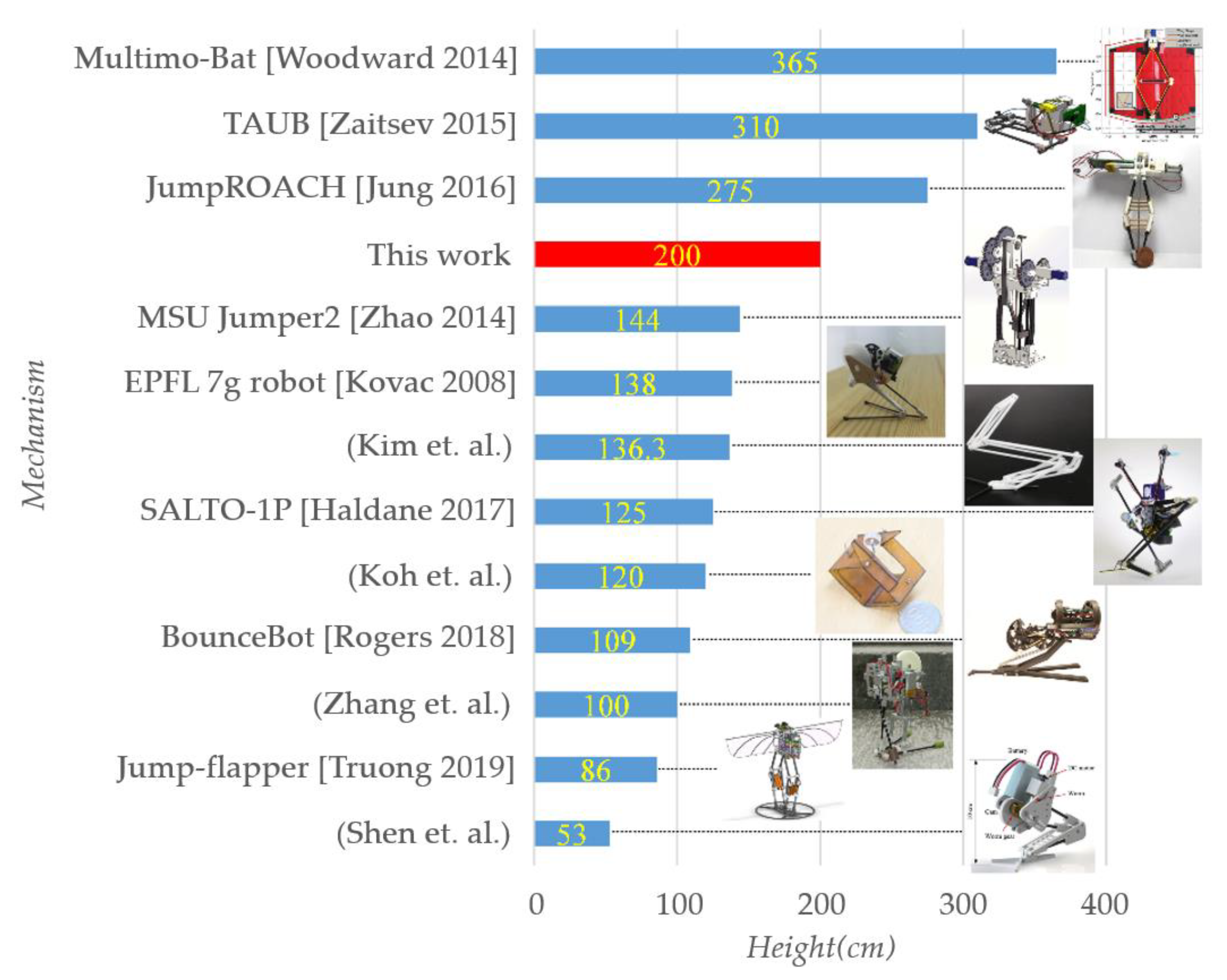
Well-known miniature jumping mechanisms proposed previously and that have good jumping performance are listed in Figure 14, and labeled with jumping height. Only bio-mimic mechanisms that are driven mechanically while launching are mentioned; other mechanisms (e.g., ones launched using chemical explosion or electro-deformation) and robots in large size, especially multilegged ones are not mentioned. Also, only the robot with best jumping-height performance is shown here among ones proposed by the same team. It could be seen that this work performs relatively well among all jumping mechanisms in the similar size.
There are still some problems to be improved in our proposed mechanism. For example, it can’t make rapid continuous jumps at present, and it needs a little time to re-store energy after each jump. What’s more, the stability control in the process of mechanism jumping also needs to be solved. At present, there are some novel solutions, such as adding tail and other measures to achieve reliable jumping direction [29], which is also the direction of our next stage improvement.
6. Conclusions
Inspired by the working method of the weevil’s jumping mechanism, where two sliders and a lever serve as the core, a new type of weevil-inspired jumping mechanism was proposed herein, thereby providing a new structure, together with its working principle and optimizing suggestions for future studies of bio-inspired miniature jumping mechanisms.
According to the kinematic analysis and simulations of the virtual prototypes and within the limits of the structural strength and motor power, the performance of the mechanism can be improved by doing the following. (1) A spring combination with greater stiffness should be adopted. (2) The projection of the COM on the ground should be kept near the front edge of the supported area but securely inside. (3) The lower string should be shortened as much as possible to lower the COM before launch. (4) The upper string should be long enough to allow the pole to be stopped by colliding with the SB.
The mechanism proposed herein works in a similar pattern with the biological structure, and in a similar appearance. Only few but effective improvements are made to the mechanism to fit engineering demands, to preserve the original working principle and apparent structure as well as possible. As a result, only one DOF is required for this mechanism, and basic requirements such as coping with uneven terrain as the launching surface or adjusting the jumping height and distance are met in this work. This 44.7 g mechanism can lift its COM by 200 cm and remain safe upon a hard landing. Its jumping performance ranks fifth among existing miniature jumping mechanisms.
Author Contributions
Made substantial contributions to the research and investigation process, reviewed and summarized the literature, wrote and edited the original draft, Y.Z.; Performed oversight and leadership responsibility for the research activity planning and execution, as well as developed ideas and evolution of overarching research aims, Z.Y.; Performed critical review, commentary and revision, as well as provided technical, and material support, Z.Y., C.G. All authors have read and agreed to the published version of the manuscript.
Funding
This work was funded by the National Key Research and Development Program of China (Grant No. 2019YFB1309600), the National Natural Science Foundation of China (Grant Nos. 52075248, 51475230, 51875282).
Institutional Review Board Statement
Not applicable.
Informed Consent Statement
Not applicable.
Data Availability Statement
Not applicable.
Conflicts of Interest
The authors declare no conflict of interest.
References
- Anderson, F.C.; Pandy, M. Storage and utilization of elastic strain energy during jumping. J. Biomech. 1993, 26, 1413–1427. [Google Scholar] [CrossRef]
- Anderson, F.C.; Pandy, M.G. A Dynamic Optimization Solution for Vertical Jumping in Three Dimensions. Comput. Methods Biomech. Biomed. Eng. 1999, 2, 201–231. [Google Scholar] [CrossRef] [PubMed]
- Jung, G.-P.; Casarez, C.S.; Lee, J.-E.; Baek, S.-M.; Yim, S.-J.; Chae, S.-H.; Fearing, R.S.; Cho, K.-J.; Fearing, R.S.; Chae, S.-H. JumpRoACH: A Trajectory-Adjustable Integrated Jumping–Crawling Robot. IEEE/ASME Trans. Mechatron. 2019, 24, 947–958. [Google Scholar] [CrossRef]
- Jung, G.-P.; Casarez, C.S.; Jung, S.-P.; Fearing, R.S.; Cho, K.-J. An integrated jumping-crawling robot using height-adjustable jumping module. In Proceedings of the 2016 IEEE International Conference on Robotics and Automation (ICRA), Stockholm, Sweden, 16–21 May 2016; pp. 4680–4685. [Google Scholar] [CrossRef]
- Woodward, M.; Sitti, M. Multimo-bat: A biologically inspired integrated jumping-gliding robot. Int. J. Robot. Res. 2014, 33, 1511–1529. [Google Scholar] [CrossRef]
- Ye, C.; Wang, B.; Wei, B.; Tang, B. Modeling and Analysis of a Jumping Robot with Deforming Wheeled Mechanism. In Proceedings of the 2018 IEEE International Conference on Mechatronics and Automation (ICMA), Changchun, China, 5–8 August 2018; pp. 980–985. [Google Scholar] [CrossRef]
- Truong, N.T.; Phan, H.V.; Park, H.C. Design and demonstration of a bio-inspired flapping-wing-assisted jumping robot. Bioinspiration Biomim. 2019, 14, 036010. [Google Scholar] [CrossRef] [PubMed]
- Zhao, J.; Xu, J.; Gao, B.; Xi, N.; Cintron, F.J.; Mutka, M.W.; Xiao, L. MSU Jumper: A Single-Motor-Actuated Miniature Steerable Jumping Robot. IEEE Trans. Robot. 2013, 29, 602–614. [Google Scholar] [CrossRef]
- Zhao, J.; Zhao, T.; Xi, N.; Mutka, M.W.; Xiao, L. MSU Tailbot: Controlling Aerial Maneuver of a Miniature-Tailed Jumping Robot. IEEE/ASME Trans. Mechatron. 2015, 20, 2903–2914. [Google Scholar] [CrossRef]
- Zhao, J.; Yan, W.; Xi, N.; Mutka, M.W.; Xiao, L. A miniature 25 grams running and jumping robot. In Proceedings of the 2014 IEEE International Conference on Robotics and Automation (ICRA), Hong Kong, China, 31 May–7 June 2014; pp. 5115–5120. [Google Scholar] [CrossRef]
- Shen, Y.; Ge, W.; Mo, X.; Hou, Z. Design of a locust-inspired miniature jumping robot. In Proceedings of the 2018 IEEE International Conference on Robotics and Biomimetics (ROBIO), Kuala Lumpur, Malaysia, 12–15 December 2018; pp. 2322–2327. [Google Scholar] [CrossRef]
- Zhang, J.; Song, G.; Li, Y.; Qiao, G.; Song, A.; Wang, A. A bio-inspired jumping robot: Modeling, simulation, design, and experimental results. Mechatronics 2013, 23, 1123–1140. [Google Scholar] [CrossRef]
- Kovac, M.; Fuchs, M.; Guignard, A.; Zufferey, J.-C.; Floreano, D. A miniature 7g jumping robot. In Proceedings of the 2008 IEEE International Conference on Robotics and Automation, Pasadena, CA, USA, 19–23 May 2008; pp. 373–378. [Google Scholar]
- Plecnik, M.M.; Haldane, D.W.; Yim, J.K.; Fearing, R.S. Design Exploration and Kinematic Tuning of a Power Modulating Jumping Monopod. J. Mech. Robot. 2016, 9, 011009. [Google Scholar] [CrossRef]
- Haldane, D.W.; Plecnik, M.M.; Yim, J.K.; Fearing, R.S. Robotic vertical jumping agility via series-elastic power modulation. Sci. Robot. 2016, 1, eaag2048. [Google Scholar] [CrossRef] [PubMed] [Green Version]
- Haldane, D.W.; Yim, J.K.; Fearing, R.S. Repetitive extreme-acceleration (14-g) spatial jumping with Salto-1P. In Proceedings of the 2017 IEEE/RSJ International Conference on Intelligent Robots and Systems (IROS), Vancouver, BC, Canada, 24–28 September 2017; pp. 3345–3351. [Google Scholar]
- Zhang, J.; Song, G.; Qiao, G.; Li, Z.; Wang, W.; Song, A. A novel one-motor driven robot that jumps and walks. In Proceedings of the 2013 IEEE International Conference on Robotics and Automation, Karlsruhe, Germany, 6–10 May 2013; pp. 13–19. [Google Scholar]
- Chen, G.; Tu, J.; Ti, X.; Hu, H. A Single-legged Robot Inspired by the Jumping Mechanism of Click Beetles and Its Hopping Dynamics Analysis. J. Bionic Eng. 2020, 17, 1109–1125. [Google Scholar] [CrossRef]
- Zhang, Z.; Chang, B.; Zhao, J.; Yang, Q.; Liu, X. Design, Optimization, and Experiment on a Bioinspired Jumping Robot with a Six-Bar Leg Mechanism Based on Jumping Stability. Math. Probl. Eng. 2020, 2020, 1–23. [Google Scholar] [CrossRef]
- Noh, M.; Kim, S.-W.; An, S.; Koh, J.-S.; Cho, K.-J. Flea-Inspired Catapult Mechanism for Miniature Jumping Robots. IEEE Trans. Robot. 2012, 28, 1007–1018. [Google Scholar] [CrossRef]
- Koh, J.-S.; Jung, S.-P.; Noh, M.; Kim, S.-W.; Cho, K.-J. Flea inspired catapult mechanism with active energy storage and release for small scale jumping robot. In Proceedings of the 2013 IEEE International Conference on Robotics and Automation, Karlsruhe, Germany, 6–10 May 2013; pp. 26–31. [Google Scholar] [CrossRef]
- Nadein, K.; Betz, O. Jumping mechanisms and performance in beetles II. Weevils (Coleoptera: Curculionidae: Rhamphini). Arthropod Struct. Dev. 2018, 47, 131–143. [Google Scholar] [CrossRef] [PubMed]
- Komarsofla, A.K.; Yazdi, E.A.; Eghtesad, M. Dynamic Modeling and Control of a Novel One-Legged Hopping Robot. Robotica 2021, 39, 1692–1710. [Google Scholar] [CrossRef]
- Ding, Y.; Park, H.-W. Design and experimental implementation of a quasi-direct-drive leg for optimized jumping. In Proceedings of the 2017 IEEE/RSJ International Conference on Intelligent Robots and Systems (IROS), Vancouver, BC, Canada, 24–28 September 2017; pp. 300–305. [Google Scholar] [CrossRef]
- Zaitsev, V.; Gvirsman, O.; Ben Hanan, U.; Weiss, A.; Ayali, A.; Kosa, G. A locust-inspired miniature jumping robot. Bioinspiration Biomim. 2015, 10, 066012. [Google Scholar] [CrossRef] [PubMed]
- Beck, A.; Zaitsev, V.; Ben Hanan, U.; Kosa, G.; Ayali, A.; Weiss, A. Jump stabilization and landing control by wing-spreading of a locust-inspired jumper. Bioinspiration Biomim. 2017, 12, 066006. [Google Scholar] [CrossRef] [PubMed]
- Rogers, J.; Page-Bailey, K.; Smith, R. BounceBot: A One-Legged Jumping Robot. In Proceedings of the 19th Annual Conference, TAROS 2018, Bristol, UK, 25–27 July 2018; pp. 52–63. [Google Scholar] [CrossRef]
- Kim, M.-J.; Yun, D. Kinematic design and system implementation of jumping robot legs. In Proceedings of the 2017 IEEE International Conference on Multisensor Fusion and Integration for Intelligent Systems (MFI), Daegu, Korea, 16–18 November 2017; pp. 592–596. [Google Scholar] [CrossRef]
- Saab, W.; Rone, W.S.; Ben-Tzvi, P. Robotic tails: A state-of-the-art review. Robotica 2018, 36, 1263–1277. [Google Scholar] [CrossRef] [Green Version]
Figure 1.
Working period (a–d) with initial and terminal phases (e–f) of weevil’s jumping mechanism. Red arrays stand for forces in muscles, green arrays stand for motions. Abbreviations: em, extensor muscle; el, extensor ligament; fm, flexor muscle; fl, flexor ligament; ip, internal protrusion; MET, metafemoral extensor tendon; TFS, tibial flexor sclerite © 2018 Elsevier Ltd. All rights reserved [22].
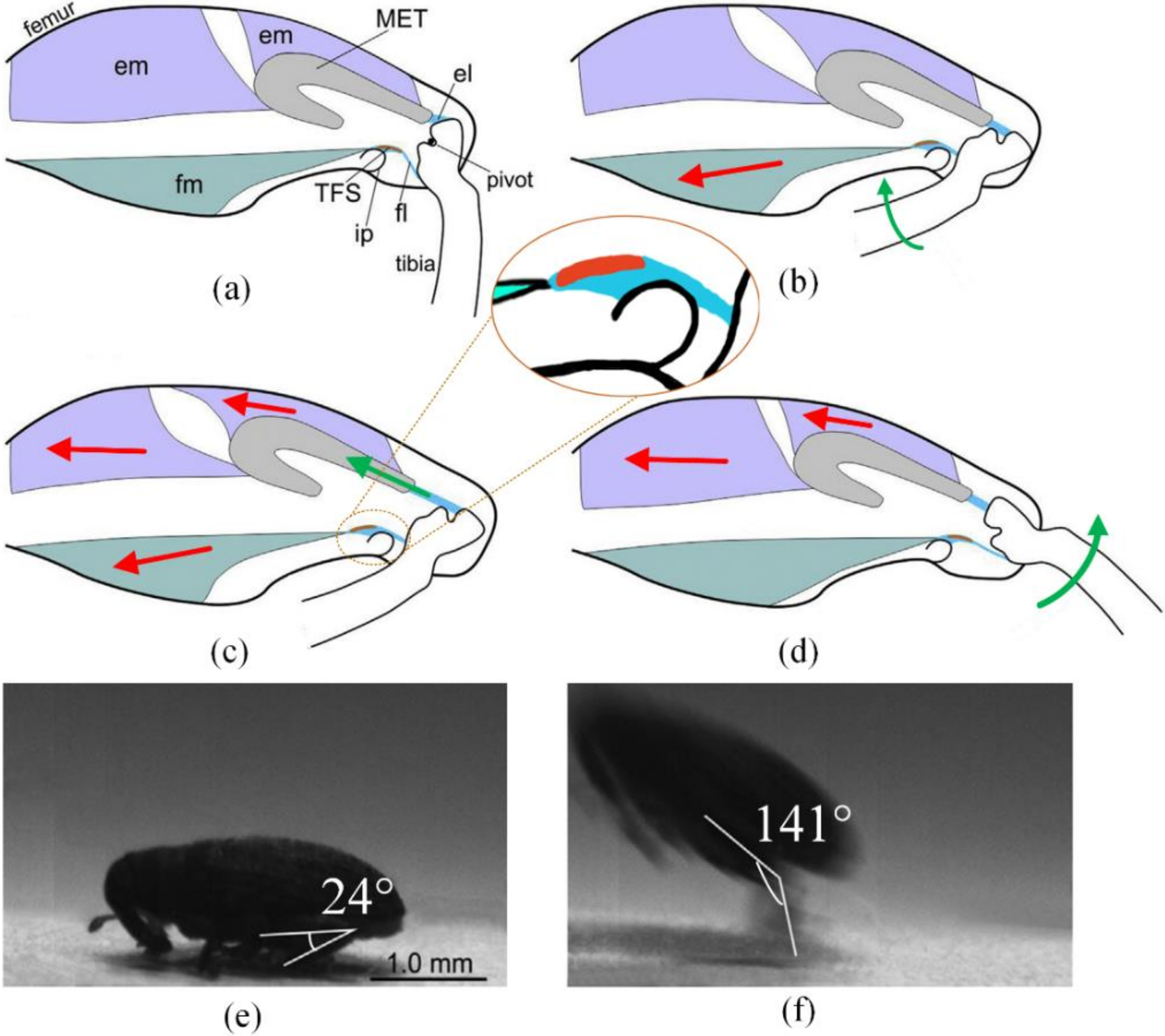
Figure 2.
Naming of parts in a side view of the device. In brackets are biological structures in corresponds. *: structures on support board (SB).
Figure 2.
Naming of parts in a side view of the device. In brackets are biological structures in corresponds. *: structures on support board (SB).
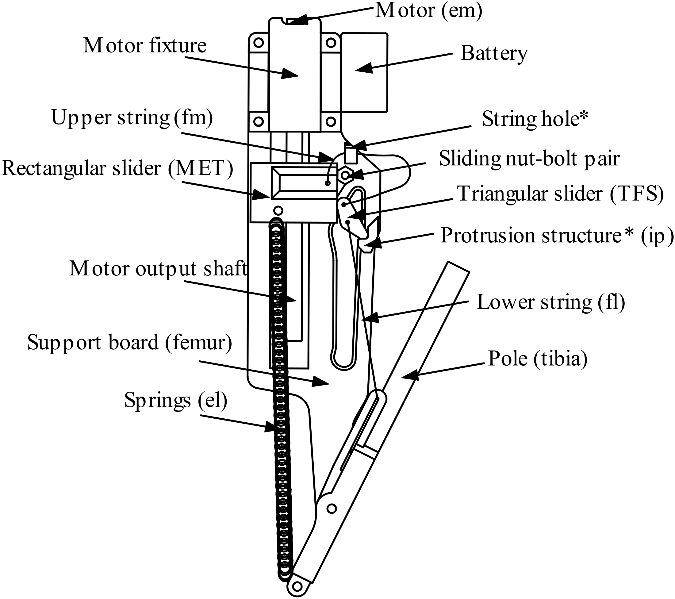
Figure 3.
Five typical stages of the mechanism with some components marked: (a) the RS moves downwards and pulls the TS moving upwards through the US; (b) the RS moves upward and the TS reaches the L-shaped PS, whereupon it rotates because of the unbalanced torque; (c) the RS continues to move upward and the pole is unable to rotate because of the pull provided by the LS; (d) the RS continues to move upward, pushing the NBP upward in its guide rail; (e) the TS falls freely down through its guide rail and the mechanism executes the launching process.

Figure 4.
Geometric model describing transmission relationship: (a) practical realization; (b) abstracted model. The thick blue lines indicate the orbit of the associated sliding dot. Meanings of dots: , hanging point of upper string on rectangle slider (RS), whose orbit is expressed in blue; , hanging point of spring on RS; U, string hole; T, triangle slider (TS); P′, position where lower string passes through the pole; P, intersection point of the extension cord of lower string and the direction of the pole (from dot O). Meanings of constants and variables: k, stiffness coefficient of serried springs; u, length of springs, , length of lower string, equals in value; , length of upper string, approximately equals + in value; , angle between y axis and OP; , angle between y axis and OP’.

Figure 5.
Curve of displacement of RS vs. angle between pole and motor output shaft (). The thick blue curve is the resetting process in which the RS moves downward. The area with a colored background is for , and that with the white background is for . The yellow dotted curve is the launching process in which the RS moves upward. The area with the yellow background is for the post-launch period, and the rest is for the pre-launch period.
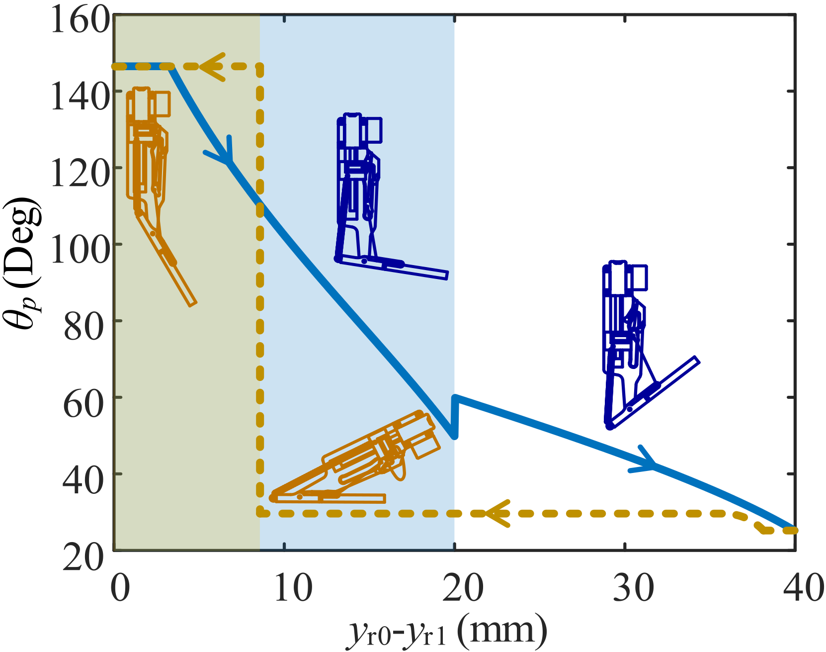
Figure 6.
Dynamic model of proposed mechanism for ejection process.
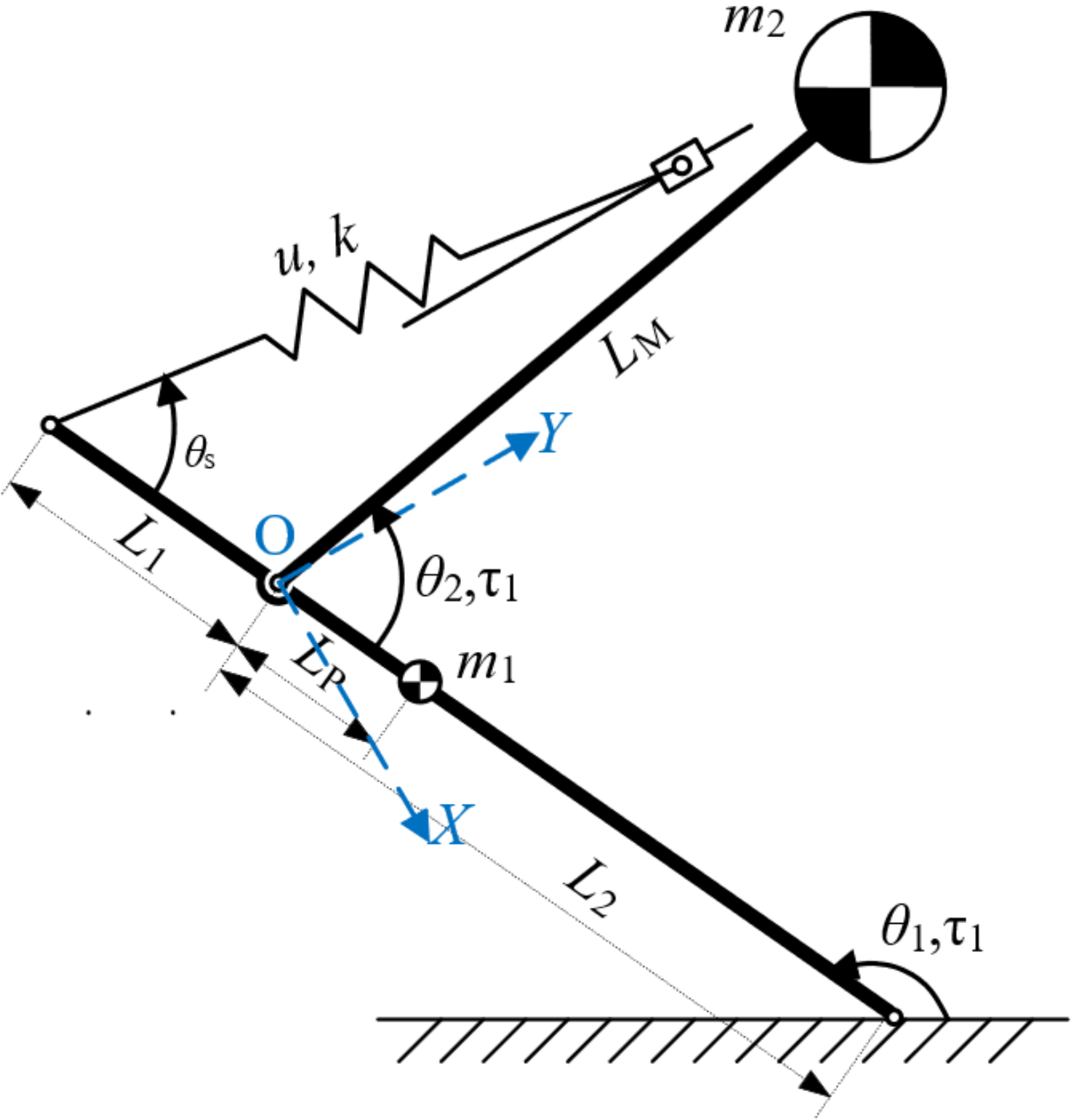
Figure 7.
Curves of dynamical indicators vs. time. Area with white background is when mechanism is in contact with the ground. Area with gray background is when mechanism is in the air.
Figure 7.
Curves of dynamical indicators vs. time. Area with white background is when mechanism is in contact with the ground. Area with gray background is when mechanism is in the air.
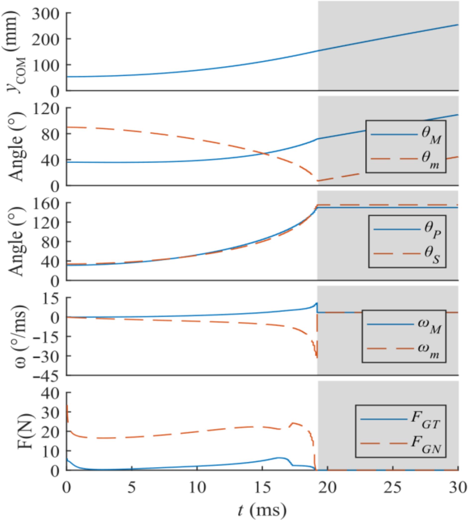
Figure 8.
Five typical stages of the mechanism with some components marked.
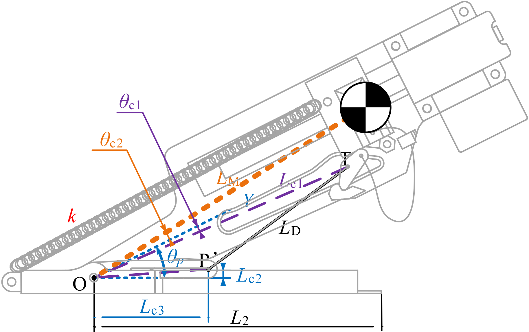
Figure 9.
Jumping performance influenced by changing the design parameters (abscissa: altered parameter; ordinate: influence indicator): (a) the indicators of ejection performance influenced by the change of the parameter k; (b) the indicators of ejection performance influenced by the change of the parameter ; (c) the indicators of ejection performance influenced by the change of the parameter ; (d) the indicators of ejection performance influenced by the change of the parameters and .
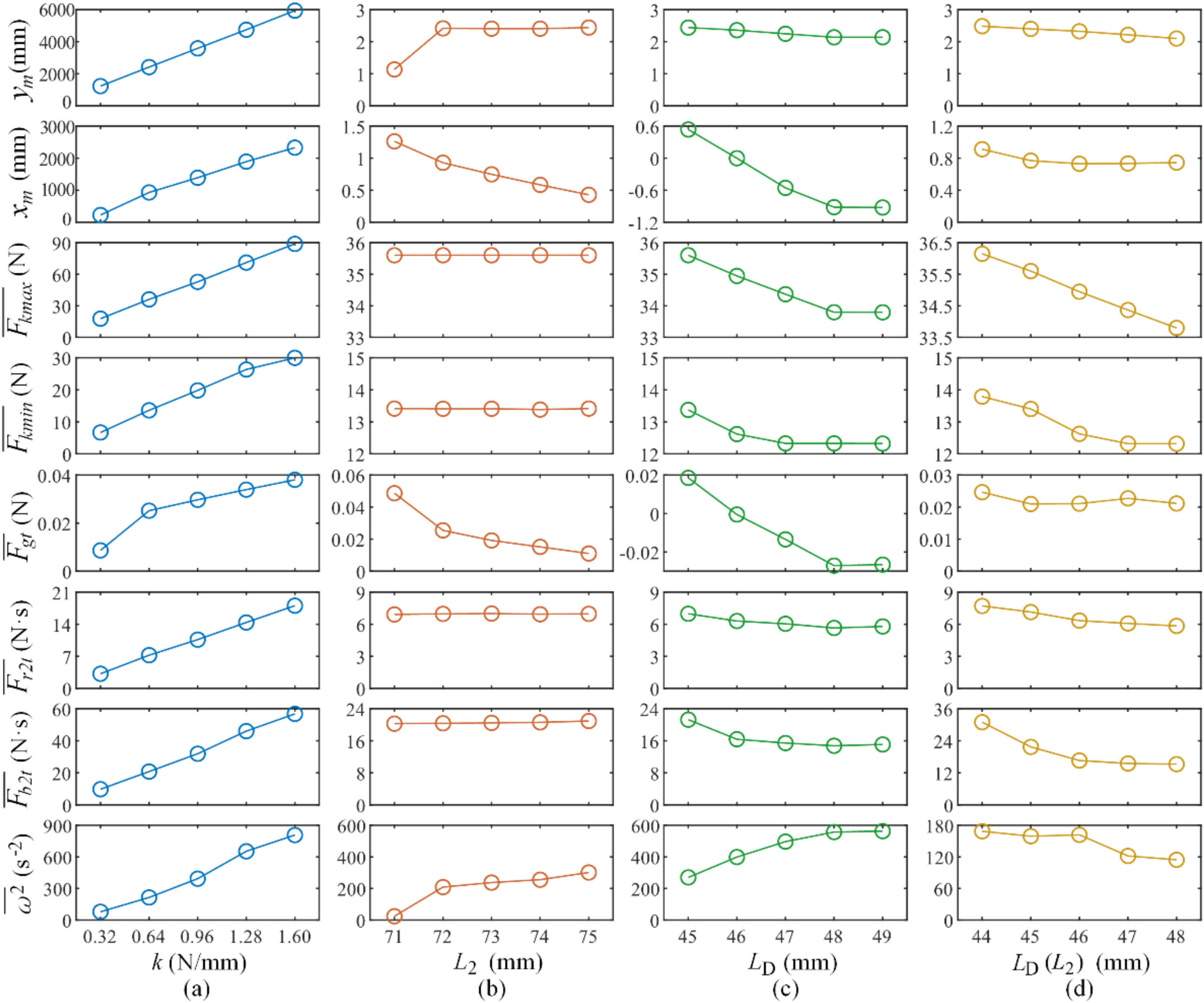
Figure 10.
Curves vs. time t [s] of some dynamical parameters, with = 0.64 and 1.28 N/mm: (a) orbit of COM of the mechanism [displacement on y axis (Y) vs. displacement on x axis (X)]; (b) time-varying trend of ; (c) time-varying trend of elastic force in serried springs (); (d) time-varying trend of tension force in upper string (); (e) time-varying trend of tension force in lower string (); (f) time-varying trend of tangential component of contact force between pole and ground (), equal to friction force between mechanism and ground (normal component of this force has the same trend after subtracting the weight of the mechanism); (g) time-varying trend of interaction force between RS and TS (); (h) time-varying trend of interaction force between support board (SB) and TS (); (i) squared angular velocity of motor ().

Figure 11.
Physical prototype.

Figure 12.
Arrayed frames during in-air process.
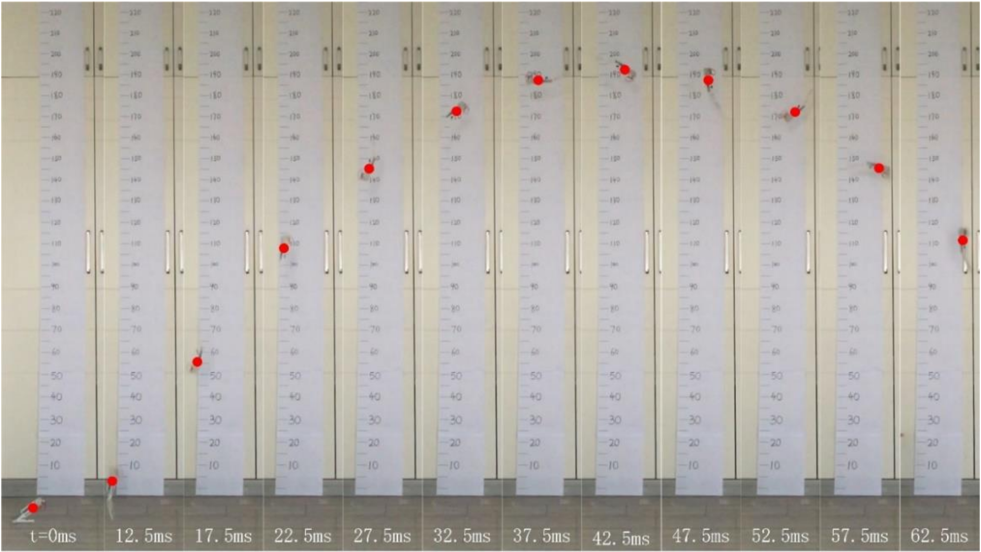
Figure 13.
Sampled vertical displacement with curve-fitting result.

Figure 14.
Listing of jumping-height performance for well-known miniature jumping mechanisms proposed previously.
Figure 14.
Listing of jumping-height performance for well-known miniature jumping mechanisms proposed previously.

Table 1.
Featured Dynamical Parameters.
| Variable Name | Definition | Practical Significance |
|---|---|---|
| Displacement on x axis at landing | Idealized horizontal displacement | |
| Displacement on y axis at apex | Idealized jumping height | |
| Maximum spring tension force | Stored elastic energy and deformation of the spring | |
| Minimum spring tension force | Unreleased elastic energy | |
| Average of tangential component of force between ground and mechanism with time | Initial horizontal velocity | |
| Average of tangential force between SB and TS with time | Interaction forces between components | |
| Average angular velocity of SB | Measure of spinning |
Table 2.
Weight budget of proposed jumping mechanism.
| Part | Mass[g] | Portion |
|---|---|---|
| Motor | 13.7 | 30.6% |
| Battery | 5.0 | 11.2% |
| Motor fixtures | 3.0 | 6.7% |
| Pole | 6.8 | 15.2% |
| SB | 6.3 | 14.1% |
| RS | 1.9 | 4.3% |
| TS | 0.2 | 0.4% |
| Springs | 4.0 | 8.9% |
| Nuts and bolts | 3.8 | 8.5% |
| Total mechanism | 44.7 | 100% |
Publisher’s Note: MDPI stays neutral with regard to jurisdictional claims in published maps and institutional affiliations. |
© 2022 by the authors. Licensee MDPI, Basel, Switzerland. This article is an open access article distributed under the terms and conditions of the Creative Commons Attribution (CC BY) license (https://creativecommons.org/licenses/by/4.0/).
Share and Cite
MDPI and ACS Style
Yu, Z.; Zeng, Y.; Guo, C. Mechanical Design and Performance Analysis of a Weevil-Inspired Jumping Mechanism. Machines 2022, 10, 161. https://doi.org/10.3390/machines10030161
AMA Style
Yu Z, Zeng Y, Guo C. Mechanical Design and Performance Analysis of a Weevil-Inspired Jumping Mechanism. Machines. 2022; 10(3):161. https://doi.org/10.3390/machines10030161
Chicago/Turabian StyleYu, Zhiwei, Yifan Zeng, and Ce Guo. 2022. "Mechanical Design and Performance Analysis of a Weevil-Inspired Jumping Mechanism" Machines 10, no. 3: 161. https://doi.org/10.3390/machines10030161
Note that from the first issue of 2016, this journal uses article numbers instead of page numbers. See further details here.