
Fabrication of Flexible Multi-Cavity Bio-Inspired Adhesive Unit Using Laminated Mold Pouring
by

Linghao Zhang
1,†, 
Liuwei Wang
1,2,†,
Zhiyuan Weng
1,
Qingsong Yuan
1,
Keju Ji
1 and
Zhouyi Wang
1,2,* 1
Institute of Bio-inspired Structure and Surface Engineering, Nanjing University of Aeronautics and Astronautics, Nanjing 210016, China
2
Nanjing University of Aeronautics and Astronautics Shenzhen Research Institute, Shenzhen 518063, China
*
Author to whom correspondence should be addressed.
†
These authors contributed equally to this work.
Machines 2022, 10(3), 184; https://doi.org/10.3390/machines10030184
Submission received: 27 January 2022
/
Revised: 25 February 2022
/
Accepted: 2 March 2022
/
Published: 3 March 2022
(This article belongs to the Special Issue Bio-Inspired Smart Machines: Structure, Mechanisms and Applications)
Abstract
:To meet the requirements for the flexible end-effectors of industrial grippers and climbing robots, inspired by the animal attachment mechanism, a bio-inspired adhesive unit (Bio-AU) was designed. Due to its fluid-driven operating characteristics and multi-level adhesive structure, its fabrication and molding is challenging, including the assembly and molding of complex cavities with good pressure-bearing capability, mechanical properties of multi-level materials with variable stiffness, etc. In this study, based on the lamination mold casting process, the “simultaneous molding and assembly” method was established, which can be applied to form and assemble complex cavity parts simultaneously. Moreover, the dovetail tenon-and-mortise parting structures were analyzed and designed. Furthermore, the adhesion between the parting surfaces can be improved using plasma surface treatment technology. By applying the above methods, the assembly accuracy and pressure-bearing capability of the complex flexible cavities are improved, which reduces the individual differences between finished products. Additionally, the maximum pressure-bearing value of the sample was 83 kPa, which is 1.75 times that before optimization. the adhesive structure with different stiffness components was fabricated at low cost using silicon rubber substrates with different properties, which met the requirements of multi-level material with variable stiffness of the Bio-AU. The bending angle of the optimized molding product was about 50.9° at 80 kPa, which is significantly larger than the 24.6° of the lighting-cured product. This indicates that the optimized lamination mold casting process has a strong inclusion of materials, which improves the deformation capacity and self-adaptability of Bio-AUs and overcomes the defects of 3D printing technology in the formation of large, flexible, and controllable-stiffness structures. In this study, the effective fabrication of flexible multilayer adhesive structures was accomplished, and technical support for the development of Bio-AUs was provided, which met the requirements of bionic climbing robots and industrial adhesive grippers for end-effectors.
1. Introduction
A flexible end-effector is an irregular flexible structure with a large deformation ability; it is typically composed of flexible materials (such as silicone and rubber). When driven by fluids and electromagnetics, among others, they can be attached to the target with high adaptivity. Therefore, the flexible end effector has unique application prospects in many fields [1,2,3], such as robot feet and flexible grippers for industrial sorting. In recent years, with the in-depth research on the bio-adhesion mechanism and the development of micro-nano manufacturing technology [4,5,6,7], biomimetic dry adhesion technology has been introduced in the field of the attachment of end-effectors. As a result, a fluid-driven flexible end-effector with an adhesive function has been developed [8,9], which can adhere to objects that are extremely difficult to grasp by friction in conventional environments, such as objects with small surface curvature, smoothness, and easy damage, thereby expanding the workable boundary of the flexible end-effector. The performance of flexible end-effectors is affected by a combination of the material properties, cavity structure, and actuation modes [10]. Based on current research on the bio-adhesion mechanism, the animal’s flexible adhesion system [11,12] is a multi-layer and cross-scale variable stiffness structure, which achieves good adhesion through the cooperation of various functional components [13]. Inspired by the multi-layer and cross-scale variable stiffness structure, the fluid-driven multi-layer adhesive cavity structure was creatively designed, of which the fabrication and molding are challenging, such as the molding of irregular cavity structures of flexible materials, the assembly and sealing of complex cavities, and the stiffness and toughness of the forming structure must meet the requirements of adhesive deformation.
Existing fabrication technologies for flexible multicavity structures are mainly divided into 3D integrated printing technologies and traditional mold casting technologies. The most used 3D integrated printing technologies, such as stereolithography (SLA) [14], fused deposition modeling (FDM) [15], and poly-jetting [16,17], are limited by the materials used in the process. A structure prepared using the SLA process (light-cured material) can withstand a maximum strain of 40%, whereas that prepared by traditional mold casting (silicone rubber material, PDMS) can withstand more than 600% strain [10]. Similarly, the shore hardness of materials used in FDM, such as Ninja-flex or TPU, is usually 80~90 A, and a large external load is required to achieve the target deformation. The material used by the poly-jetting technology is closer to PDMS than the above two technologies, which has better flexibility and elasticity. Although the poly-jetting technology can realize a mixed and integrated printing of materials with different stiffnesses, the expensive equipment has a low performance-price ratio. Traditional mold casting technologies, which include lamination molding [10,18], lost-wax casting [19], and rotational molding [20], can be used to fabricate simple structural models. Meanwhile, this technology is inexpensive, and the material used is flexible and elastic. However, in view of the fabrication requirements of the Bio-AU, its complex multicavity structure cannot be fabricated integrally by lamination mold casting, and it needs to be poured in layers and bonded using adhesives, which challenge the assembly accuracy and pressure-bearing capability of the complex multi-cavity structure. Lost wax casting technology, which makes the paraffin inner mold first and dissolves the inner mold through a high temperature or a water bath after the pouring is completed, can be used to fabricate the complex multi-cavity structure integrally. However, this method involves complicated processing steps, and it is difficult to completely remove the residual paraffin, which ultimately affects the adhesion performance of the Bio-AU. Compared with other fabrication processes, the lamination mold casting process is highly sensitive to the complexity of the structure, making it difficult to fabricate the cavity integrally using this process, although it is more inclusive of materials and can be applied to a wide range of materials. Therefore, cavity assembly technology can be improved based these considerations, which can improve the fatigue resistance and pressure-bearing capability of the cavity to meet the fabrication requirements of the Bio-AU.
In this paper, owing to the preparation and molding requirements of complex multi-cavity Bio-AUs, the existing processing technologies were compared. It is understood that the existing traditional lamination mold casting cannot guarantee the assembly accuracy and pressure bearing capacity of the cavity, and the 3D printing technology is limited by the base material. Therefore, based on the lamination mold pouring (divided cavity preparation, combined assembly) technology, the cavity assembly process was optimized. The parting surface structure is directly related to the assembly accuracy and structural bearing performance of the multi-layer cavity, thereby affecting the pressure bearing capability and fatigue resistance of the toe, and also affecting the design of the mold. First, the parting surface and mold design of the flexible multi-cavity Bio-AU were carried out, and the structural design of the parting surface of the dovetail tenon and tenon was carried out to improve the fatigue resistance and compression resistance of the cavity. Then, the preparation and molding of the flexible Bio-AU were introduced from the selection and formulation of the substrate and the specific production process. Three process methods were introduced: the lamination mold casting (“divided cavity molding-integrated assembly,” DCMA) process; the optimized lamination mold casting (“simultaneous molding and assembly,” SMA) process; and the stereolithography (SLA) 3D printing technology. Finally, in order to evaluate the performance of the optimized lamination mold casting process, the bending and pressure-bearing properties of the three types of samples prepared by the three processes were compared and tested, and the application of the Bio-AU was demonstrated.
2. Parting Surface and Mold Design of the Bio-AU with Flexible Multi-Cavity
2.1. Forming Requirements
The design of the soft multi-cavity Bio-AU was inspired by the geckos’ cross-layer variable stiffness adhesion system, as well as its reversible adhesion-detachment behavior. It is a flexible multi-cavity structure with a sheet-like bionic flexible skin flap attached to the abdomen. It expands to bend towards the abdomen when driven by positive pressure, enveloping, and adhering to the target. Additionally, it contracts to bend toward the back side when driven by negative pressure, detaching from the target. These behaviors are similar to the adaptive stable adhesion and valgus detachment of geckos. As a type of adhesive unit, the Bio-AU is required to have good intrinsic flexibility to adaptively envelope and adhere to the object, together with a certain rigidity to drive the underlying flap structure and lift the Bio-AU adhesion (Figure 1). Therefore, the preparation and molding of flexible multi-cavities of Bio-AUs with variable stiffness characteristics (complex soft multi-cavity with excellent flexibility, high pressure-bearing capability, and significant differences in stiffness and deformation at each layer) is the basis of their function, which is a significant challenge for future research on bionic climbing robots. To ensure that the multi-cavity structure has the required compression and deformation capabilities, dovetail tenon and tenon parting surface structures were designed to enhance the bonding performance and the pressure-bearing capability of the Bio-AU. The mold design and specific fabrication process of the Bio-AU were established to realize the fabrication and molding of the AUs’ complex soft multi-cavities.
2.2. Parting Surface Design
Based on lamination mold casting technology, the Bio-AU was fabricated in separate cavities and assembled together. The structure of the parting surface is directly related to the assembly accuracy of the multi-cavity, thereby affecting the compression and fatigue resistance of the cavity. Inspired by the traditional stable tenon-and-mortise structure, a dovetail tenon-and-mortise parting surface is designed.
First, the influence of different parting surfaces on the mechanical properties of interfacial bonding was studied. The failure mode of the cavity expansion to the parting surface is usually vertical interfacial separation. When the inner cavity of the Bio-AU was loaded, the effect on the parting surface could be simplified by applying a vertical interfacial separation force on the parting surface. To simulate the above process, a simplified two-dimensional finite element model of the parting surface was established in Abaqus (SIMULIA, Dassault System, Providence, RI, USA), as shown in Figure 2b. The lower parting surface was fixed, while the upper parting surface was displaced along the vertical direction until it was completely separated. The interfacial separation force and avulsion energy (See the Supplementary Materials for measurement methods of both), which were generated throughout the separation process, were extracted and used as evaluation criteria for the stable performance of the parting surface structure. The Mooney-Rivlin model was used to describe the silicone rubber material used for the fabrication of the Bio-AUs. The cohesive force model (bilinear constitutive model) was introduced to describe the adhesive connection and failure behavior between the two interfaces. The maximum nominal stress criterion was selected as the evaluation criterion for damage initiation, in which the maximum stress value was set to 0.15 MPa, and the maximum avulsion displacement was set to 5 × 10⁻⁴ mm. Finite element models of three different parting surface structures (plane, right-angle tenon-and-mortise (RTM), and dovetail tenon-and-mortise (DTM)) are shown in Figure 2a,b. Under the same displacement, the failure states of the interfaces were analyzed and compared. Figure 2c shows that the maximum interfacial separation force required for the three parting surface structures is approximately the same, whereas the DTM structure with the mechanical locking feature results in the rebound of the interfacial separation force during the damage failure stage. Meanwhile, Figure 2d shows that the average energy required for the complete separation of the DTM parting surface structure is the largest.
To optimize the pressure-bearing capability of the DTM parting surface, four structural parameters were studied: the length of the short side of the tenon , the height of the vertical tenon , the length of the long side of the tenon and the fixed overall length (Figure 2b) (three levels of , and were set as shown in Table S1 of the Supplementary Materials). The orthogonal experimental method was used to extract representative combinations for comparison (Table 1). As shown in Figure 3a,b, the maximum interfacial separation forces of the nine parting surfaces are approximately the same. However, the best performance was from the test No. III parting surface, where its interfacial separation force has an obvious rebound during the damage stage, and its avulsion energy reached 0.43 mJ, which is nearly 1.6 times that of the test No. Ⅷ parting surface (Figure 3c). Therefore, the test no. III parting surface was selected for fabricating the Bio-AU cavity.
2.3. Mold Design
Based on the lamination mold casting technology, the Bio-AU is divided into three parts: upper cavity fold, lower cavity abdomen, and skin flap. These were independently fabricated and assembled. The upper cavity fold was combined with the lower cavity abdomen through the DTM parting surface. Due to the Bio-AU with complex structure, the following challenges will be encountered during the fabrication process: (a) efficient filling of silicone during the pouring of the complex structures: such as thorough release of air bubbles, rapid replenishment, etc. (b) effective fabrication and rapid demolding of large slenderness ratio structures (such as thin flap layers).
Regarding the above challenges, the following solutions were proposed:
- Arranging the position and number of vents and feeding grooves reasonably: To avoid the complex multi-cavity structure, the vents were mostly located at the joint surface. In addition, the vents could be used as injection ports and exhaust ports simultaneously. Garbage chutes were set around the joint surface, which could accelerate the release of air bubbles and the replenishment of the mold from all around (Figure 4a).
- Using tapered pins and screws to locate and lock between male and corresponding female molds. Taper pins are precisely located and easy to separate, while screws can not only ensure the stability of mold clamping, but also facilitate disassembly.
- To take out the finished product from the mold smoothly, a certain draft angle was set at the position of complex structures such as cavity folds. And notches were designed on each mold to separate the male and female molds using tools.
- Large slenderness ratio structures (such as thin flap layers) are difficult to demold due to their different axial strengths but uniform radial stiffness. In order to ensure the quality of finished products, the molds with a radial demolding direction were designed, which were symmetrically divided along the axis. In this way, the axial tearing is avoided during demolding (see Figure 4c).
The above molds are all laser sintered by Shenzhen Future Factory using 7500 high-performance nylon material, which has the characteristics of high temperature resistance, high strength, high surface quality, and easy demolding (See the Supplementary Materials for calculations related to mold design).
3. Fabrication and Molding of Bio-AUs
3.1. Selection and Formulation of Variable-Stiffness Substrates for Bio-AUs
The Bio-AU has requirements of high deformation and outstanding adaptability, which presents challenges to the fabrication process. When driven by pressure, the upper cavity fold should be easily deformed, while the lower cavity abdomen should maintain a certain stiffness and toughness to drive the underlying flap structure. Furthermore, the flap should also maintain a certain stiffness for rapid detachment. Therefore, the Bio-AU should be a multi-layer structure with variable stiffness, which means that the selection and formulation of materials are determined by the requirements in stiffness and deformation of Bio-AUs’ each layer.
Polydimethylsiloxane (PDMS) is a commonly used flexible silicone rubber material. It is known that its elastic modulus ranges from 0.83 to 1.23 MPa under different curing conditions [21], which is difficult to meet the Bio-AU’s requirements of structural variable stiffness. Studies [22] have shown that the elastic moduli of materials can be significantly improved by adding second phase particles (such as SiO2, Fe3O4, etc.) to PDMS. Meanwhile, the addition of Ecoflex material, which belongs to the same type of silicone but has a lower elastic modulus and higher toughness than PDMS, can make the Bio-AU maintain high flexibility as well as a certain toughness [23]. Overall, PDMS (Dow Corning 184) was selected as the base material, while the Ecoflex 0030 series (Smooth-On Company) and the nano-silica fume SiO2 (Maclean Company) were used as the auxiliary materials. Finally, component A and B materials were formulated by using the above materials (see Table 2).
According to the standard for dumbbell tensile samples specified in D412-98a, the elastic modulus of component A and B materials were studied. Four dumbbell tensile test samples were respectively cast for each component materials using a mold (Figure 5a). At the experimental temperature of 24 °C, the tensile testing machine (Figure 5b) was controlled to stretch at a constant rate of 500 ± 50 mm/min. The results show that the elastic moduli of component A and B materials are respectively 0.9 MPa and 1.74 MPa (Figure 5c), which illustrates that flexible materials with different stiffness can be formulated by using auxiliary materials. Therefore, in order to meet the mechanical performance requirements of the Bio-AU, the upper cavity fold was endowed with component A material, while the lower cavity abdomen and skin flap structure were endowed with component B material.
Additionally, the stiffness adjustment technology of the flexible cavity (embedded objects) was also studied, which can meet the variable stiffness requirements of the Bio-AU with multi-layer structure under different working conditions. The component C material in Table 2 is T700 Carbon Fiber Board (elastic modulus ≥ 200 GPa; tensile strength ≥ 3500 MPa), whose stiffness is much higher than that of both component A and B materials. The local stiffness can be significantly increased by cutting carbon fiber plates into sheets and evenly embedding them in the flexible cavity. And the stiffness can be adjusted within a certain range by changing the distribution density of the carbon fiber sheets. Therefore, when the technology is applied to the lower cavity abdomen, its strength can be significantly improved, thereby ensuring the adaptability of the Bio-AU and improving its adhesion.
3.2. Fabrication Process
The lamination mold casting usually adopts the process of “divided cavity molding-integrated assembly,” i.e., after the flexible cavities are poured independently in layers, the cavity is assembled using the adhesive (silicon with the same properties). This type of process has low assembly accuracy and uneven bonding, resulting in cavities with large differences in individual performance and low pressure-bearing capability, which cannot meet the requirements of bonding and assembly. For this reason, the lamination mold casting process was optimized by adopting the process of “simultaneous molding and assembly” (Figure 6b). In this process, the upper cavity is fabricated in advance, and the assembly of the upper and lower cavities is accomplished simultaneously during the curing process of the lower cavity. This process can ensure the assembly accuracy of cavities, and the adhesion between the parting surfaces is enhanced using plasma surface oxidation treatment technology, which improves the pressure-bearing capability of the Bio-AU.
For the purpose of reflecting the characteristics of the proposed “simultaneous molding and assembly” process, three processing methods (the DCMA process (Figure 6a), SMA process (Figure 6b), and SLA technology (Figure 6c) were introduced and compared.
- DCMA: The Bio-AU is divided into three parts: upper cavity fold, lower cavity abdomen, and skin flap. These were independently fabricated and assembled. Subsequently, the cavity and the skin flap were assembled sequentially using the adhesive (the same flexible material). The process is as follows:
Divided cavity molding: (1) Spraying release agent on the surface of upper cavity fold/lower cavity abdomen/skin flap mold respectively, and pouring silicone rubber material into the corresponding female mold; (2) Clamping the mold and removing the bubbles from the mold (4~6 h in the environment of vacuum degree ≥ 100 kPa); (3) Oven heating and curing (100 °C for 50 min), followed by demolding and taking out the finished product; (4) Putting the finished product into the plasma surface treatment machine for surface oxidation treatment;
Integrated assembly: Cavity and flap assembly are performed sequentially. During the assembly process, the adhesive (component B in Figure 5) should be evenly applied to the cavity parting surface, while the flap is bonded to the lower surface of the cavity. Before the heat curing step (30 min at 100 °C), each assembled part needs to be pressed tightly. The release agent material used in the process is Release 200 spray release agent (Smooth-On Company). In addition, studies have confirmed that the bonding effect between PDMS treated with oxygen plasma will be improved [24].
- 2.
- SMA: Steps (1) to (4) are consistent with the DCMA, which involves making the upper cavity fold finished product; (5) Spraying the release agent on the surface of the lower cavity mold and the baffle, and installing the upper cavity in the female mold of the lower cavity, followed by the baffle and the lower cavity mold, and finally locking the molds; (6) pouring silicone rubber into the lower cavity mold and releasing air bubbles from the mold (4–6 h in an environment of vacuum degree ≥ 100 kPa); (7) oven heating and curing (100 °C for 50 min), followed by demolding and removing the finished cavity with a baffle plate; (8) pulling out the baffle to obtain the final cavity product. In addition, the fabrication process of the flap was the same as that for the DCMA. The flap was bonded to the lower surface of the cavity using an adhesive (component B in Figure 5).
The core steps of this process are Steps (5)–(8). Specifically, the upper cavity folded product is embedded in the lower cavity abdominal mold, and the baffle plate (The molds are shown in Figure 4b) prevents the flexible material from blocking the upper cavity fold. This process ensured that the assembly of the upper and lower cavities was accomplished simultaneously during the curing process of the lower cavity. However, because of the difficulty in demolding the flap with a complex and fragile structure, it is difficult to apply the SMA process to fabricate the flap. Therefore, a flexible adhesive was used to assemble the cavity and skin flap. Furthermore, the variable stiffness requirements of the Bio-AU with the multi-layer structure under different working conditions can be satisfied by combining the stiffness adjustment technology (embedded objects) and the SMA process, as shown in the lower left corner of Figure 6 (The molds are shown in Figure 4(b’-1,b’-2)).
- 3.
- SLA: By applying this technology, the Bio-AU can be integral fabricated without dividing it separately. The process is as follows: (1) importing the 3D model and printing; (2) taking out the finished product to be processed; (3) cleaning the finished product to be processed; (4) processing the finished product support and performing secondary curing; (5) taking out the final product.
In conclusion, when the SMA process is applied, the cavity can be fabricated without using the adhesive. Additionally, based on the plasma surface treatment technology, the assembly accuracy of the cavity is ensured, and the pressure-bearing capability of the cavity structure is improved. Although the steps of light-curing integrated molding technology are simple, the materials used are not as good as traditional silicone rubber materials in terms of strain capability and tensile strength. According to the deformation requirements of the Bio-AU at different layers, the lamination mold pouring process can formulate materials with different elastic moduli at a low cost, while the mixed-material 3D printer equipment is expensive and cost-effective. Therefore, when facing the formation of irregular cavity structures based on flexible materials, the fabrication and assembly of complex cavities, and the demand for flexible adhesive cavities with variable stiffness and high toughness, the optimized lamination mold casting process proposed in this study can provide a feasible solution.
4. Performance Tests and Results
In this section, the performance of the finished samples fabricated using the above three processes were studied and compared respectively, which can test the feasibility of the DCMA process. It includes the bending performance (bending angle ) and pressure-bearing capability (pressure-bearing range) of the Bio-AU under different air pressure values. The definition of the pressure-bearing range is as follows: when the positive pressure is broken, the air pressure value of the Bio-AU is the maximum positive pressure value; when the Bio-AU is upturned under negative pressure and the deformation is stable, the initial air pressure value of the Bio-AU is the maximum negative pressure value. In this study, the machine with SLA technology is Form3 (Formlabs, Boston, USA). The material used is flexible resin elastic 50 A, the elastic modulus of which is about 2.89 Mpa, and its hardness after secondary curing is 50 A. The weights of the finished Bio-AU samples fabricated by the three processes above were measured to be 26.9 (±0.53) g, 26.7 (±0.31) g and 27.9 (±0.16) g, respectively. The performance test platform includes the pneumatic drive system (Figure 7), the Bio-AU fixture and the image acquisition device (See the Supplementary Materials for instructions for use of the pneumatic drive system).
4.1. Comparison of the Bending Performance and Rupture Failure
Figure 8 shows the bending and pressure-bearing properties of the Bio-AU samples fabricated using the above three processes. The angle between the line connecting the first and last points of the Bio-AU and the horizontal line was defined as the bending angle of the Bio-AU (Figure 8a). As shown in Figure 8a, because both the DCMA and SMA processes belong to the lamination mold casting process, the bending angles of the respective samples are similar under the same pressure, and the rupture failure of the respective samples occurs at the parting surface. The size of the rupture opening of the DCMA sample is significantly larger than that of the SMA sample, which illustrates that the cavity fabricated by the SMA process has a higher assembly accuracy and pressure-bearing capability. When the driven pressure was 80 kPa, the bending angle of the SMA sample was approximately 50.9°, which was significantly larger than that of the SLA sample (24.6°), indicating that the bending performance of the SMA sample was better than that of the SLA sample under the same pressure.
4.2. Comparison of the Pressure-Bearing Capability
The pressure-bearing capability is another important performance index of the Bio-AU. Therefore, the pressure-bearing capabilities of the samples fabricated using these three processes were studied. In this way, five samples were made by using each process, leading to a total of 15 samples, whose pressure-bearing ranges were tested. Specifically, the average pressure-bearing ranges of the DCMA, SMA, and SLA samples were −68.24 to 47.98 kPa, −79.44 to 83.72 kPa, and −111.73 to 130.11 kPa, respectively. Because of the inherent advantage of the one-piece molding process, the pressure-bearing range of the SLA sample was better than that of the DCMA and SMA samples. Meanwhile, the SMA process effectively increased the pressure-bearing capability of the sample by simultaneously forming and assembling the cavity. The results show that the maximum pressure bearing of the SMA sample is nearly 1.74 times that of the DCMA sample, which narrows the gap between the SMA and SLA samples. The results in Figure 8c,d show that the individual differences between the SMA and SLA samples are small. Because the cavity of the DCMA sample is assembled by adhesive bonding, the DCMA samples have low assembly accuracy, uneven bonding, and large individual performance differences.
4.3. Application
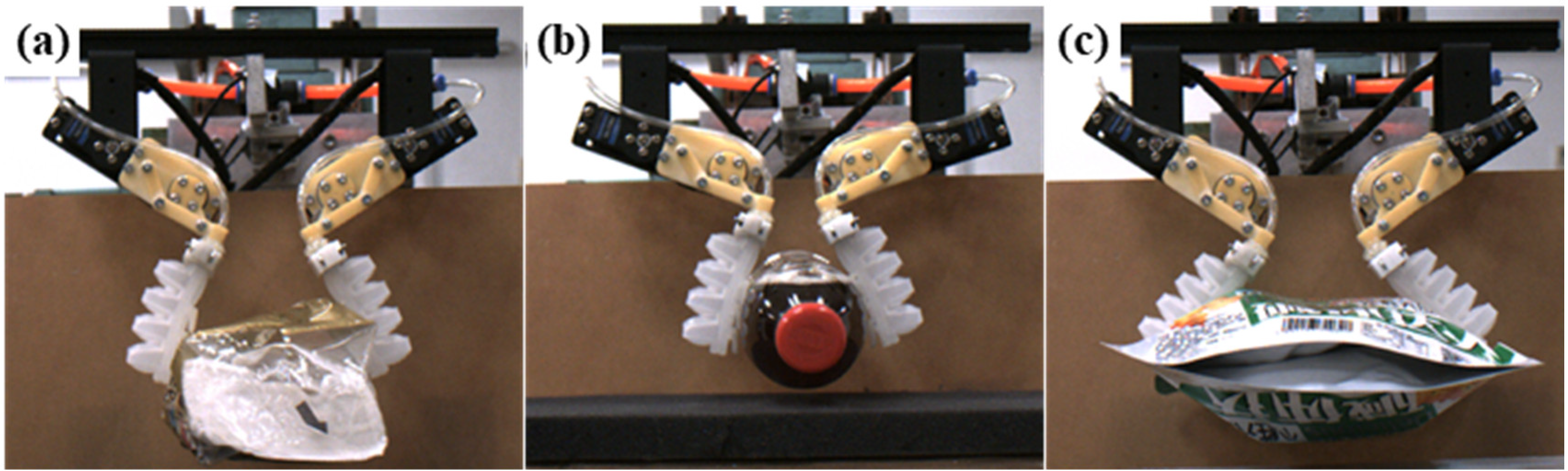
To verify the rationality of both the structure design and the adhesion performance of the Bio-AU, the adhesion-locking mechanism with the Bio-AU was used to carry out the adhesive grasping experiment on targets with different structures (Figure 9). As shown in Figure 9, for objects with irregular shapes and rigid or flexible objects, the adhesion-locking mechanism not only can achieve stable adhesion by self-retracting and self-locking, but also accomplish rapid detachment by extension. The results show that the Bio-AU has good surface adaptability. Therefore, the new adhesion operation mode with the good surface adaptability and excellent adhesion capability can effectively reduce the damage to the target while working stably.
5. Conclusions
Owing to difficulties in the fabrication and molding of fluid-driven multi-layer variable-stiffness adhesive structures, a lamination mold casting process using “simultaneous molding and assembly” method was proposed, which can be applied to form and assemble complex cavity parts simultaneously. Compared with traditional lamination mold casting process, this process can solve the dependence of cavity structure assembly on adhesive performance, resulting in the improvement of the assembly accuracy of the complex flexible cavities. Meanwhile, the fatigue resistance and pressure-bearing capability of the complex flexible cavities can be improved by the application of the dovetail tenon-and-mortise parting structures combined with the plasma surface treatment technology. The results of pressure-bearing tests show that the individual differences between finished products prepared by optimized process are small, and the maximum pressure-bearing value of the sample was 83 kPa, which is 1.75 times that before optimization. Additionally, the Bio-AU was fabricated using silicon rubber substrates with different properties, whose elastic modulus of the upper cavity fold was 0.9 MPa, and that of the lower cavity abdomen and flaps was 1.74 MPa, which met the requirements of multi-level material with variable stiffness of the Bio-AU. Compared with 3D printing, the optimized lamination mold casting process has a strong inclusion of materials, which improves the deformation capacity and self-adaptability of Bio-AUs and overcomes the defects of 3D printing technology in the formation of large, flexible, and controllable-stiffness structures. The results of bending performance tests show that the bending angle of the optimized molding product was about 50.9° at 80 kPa, which is significantly larger than the 24.6° of the light cured product.
In this study, the effective fabrication of flexible multilayer adhesive structures was accomplished, and technical support for the development of the Bio-AU was provided, which meets the requirements of bionic climbing robots and industrial adhesive grippers for end-effectors. However, owing to the challenge of miniaturization of the cavity structure with variable stiffness of complex multi-level materials, it will involve the processing and forming of the mold, the assembly of the cavity and the efficient demolding of the finished product, etc., and it is necessary to optimize or explore a new type of lamination mold casting process.
Supplementary Materials
The following supporting information can be downloaded at: https://www.mdpi.com/article/10.3390/machines10030184/s1, Figure S1: Bilinear Constitutive Model, Table S1 Three factors and their corresponding levels.
Author Contributions
L.Z. and L.W. made equal contributions to this study; Z.W. (Zhouyi Wang) and L.Z. conceived the ideas and designed the methodology; Z.W. (Zhouyi Wang) and K.J. provided guidance; L.Z. and L.W. carried out the lab experiment and completed simulation analysis; L.Z. and L.W. wrote manuscript; Z.W. (Zhiyuan Weng) and Q.Y. collected and analyzed the data. All authors have read and agreed to the published version of the manuscript.
Funding
This work was supported by the National Key R&D program of China (2019YFB1309600), National Natural Science Foundation of China (Grant No. 51975283 to Zhouyi Wang and 52075249 to Keju Ji) and Basic Research Program of ShenZhen (JCYJ20210324122810033).
Data Availability Statement
The data presented in this study are available on request from the corresponding author. The data are not publicly available due to [the unpubulished work about the design of the Bio-AUs].
Acknowledgments
We thank Xiao Yin for participating in the experiments. We also appreciate Yi Song and Jiwei Yuan for modifying the manuscript.
Conflicts of Interest
The authors declare that they have no competing interests.
Abbreviations
Bio-AU: bio-inspired adhesive unit; SLA: stereolithography, FDM: fused deposition modeling; DCMA: divided cavity molding-integrated assembly process; SMA: simultaneous molding and assembly process; RTM: right-angle tenon-and-mortise; DTM: dovetail tenon-and-mortise; PDMS: Polydimethylsiloxane.
References
- Jing, Z.; Qiao, L.; Pan, H.; Yang, Y.; Chen, W. An Overview of the Configuration and Manipulation of Soft Robotics for On-Orbit Servicing. Sci. China Inf. Sci. 2017, 5, 1–19. [Google Scholar] [CrossRef]
- Cianchetti, M.; Laschi, C.; Menciassi, A.; Dario, P. Biomedical Applications of Soft Robotics. Nat. Rev. Mater. 2018, 3, 143–153. [Google Scholar] [CrossRef]
- Zhang, B.; Xie, Y.; Zhou, J.; Wang, K.; Zhang, Z. State-Of-The-Art Robotic Grippers, Grasping and Control Strategies, as Well as their Applications in Agricultural Robots: A Review. Comput. Electron. Agric. 2020, 177, 105694. [Google Scholar] [CrossRef]
- Wang, Z.Z.; Xu, Y.; Gu, P. Adhesive Behaviour of Gecko-Inspired Nanofibrillar Arrays: Combination of Experiments and Finite Element Modelling. J. Phys. D Appl. Phys. 2012, 45, 14. [Google Scholar] [CrossRef]
- Gorb, S.; Varenberg, M.; Peressadko, A.; Tuma, J. Biomimetic Mushroom-Shaped Fibrillar Adhesive Microstructure. J. R. Soc. Interface 2007, 4, 271. [Google Scholar] [CrossRef] [PubMed] [Green Version]
- Gorb, S.N.; Varenberg, M. Mushroom-Shaped Geometry of Contact Elements in Biological Adhesive Systems. J. Adhes. Sci. Technol. 2007, 21, 1175–1183. [Google Scholar] [CrossRef]
- Sitti, M.; Fearing, R.S. Nanomolding Based Fabrication of Synthetic Gecko Foot-Hairs. In Proceedings of the 2002 2nd IEEE Conference on Nanotechnology, Washington, DC, USA, 28–28 August 2002. [Google Scholar]
- Glick, P.; Suresh, S.A.; Ruffatto, D.; Cutkosky, M.; Tolley, M.T.; Parness, A. A Soft Robotic Gripper with Gecko-Inspired Adhesive. IEEE Robot. Autom. Lett. 2018, 3, 903910. [Google Scholar] [CrossRef]
- Hao, Y.; Biswas, S.; Hawkes, E.W.; Wang, T.; Zhu, M.; Wen, L.; Visell, Y. A Multimodal, Enveloping Soft Gripper: Shape Conformation, Bioinspired Adhesion, and Expansion-Driven Suction. IEEE Trans. Robot. 2020, 37, 350–362. [Google Scholar] [CrossRef]
- Mosadegh, B.; Polygerinos, P.; Keplinger, C.; Wennstedt, S.; Shepherd, R.F.; Gupta, U.; Shim, J.; Bertoldi, K.; Walsh, C.J.; Whitesides, G.M. Soft Robotics: Pneumatic Networks for Soft Robotics that Actuate Rapidly (Adv. Funct. Mater. 15/2014). Adv. Funct. Mater. 2014, 24, 2109. [Google Scholar] [CrossRef]
- Autumn, K.; Sitti, M.; Liang, Y.A. Evidence for Van Der Waals Adhesion in Gecko Setae. Proc. Natl. Acad. Sci. USA 2002, 99, 12252–12256. [Google Scholar] [CrossRef] [PubMed] [Green Version]
- Autumn, K.; Gravish, N. Gecko Adhesion: Evolutionary Nanotechnology. Philos. Trans. R. Soc. A Math. Phys. Eng. Sci. 2008, 366, 1575–1590. [Google Scholar] [CrossRef] [PubMed]
- Tian, Y.; Wan, J.; Pesika, N.; Zhou, M. Bridging Nanocontacts to Macroscale Gecko Adhesion by Sliding Soft Lamellar Skin Supported Setal Array. Sci. Rep. 2013, 3, 1382. [Google Scholar] [CrossRef] [PubMed] [Green Version]
- Peele, B.N.; Wallin, T.J.; Zhao, H.; Shepherd, R.F. 3D Printing Antagonistic Systems of Artificial Muscle Using Projection Stereolithography. Bioinspiration Biomim. 2015, 10, 55003. [Google Scholar] [CrossRef] [PubMed]
- Yap, H.K.; Ng, H.Y.; Yeow, C.H. High-Force Soft Printable Pneumatics for Soft Robotic Applications. Soft Robot. 2016, 3, 144–158. [Google Scholar] [CrossRef]
- Drotman, D.; Jadhav, S.; Karimi, M.; de Zonia, P.; Tolley, M.T. 3D Printed Soft Actuators for a Legged Robot Capable of Navigating Unstructured Terrain. In Proceedings of the 2017 IEEE International Conference on Robotics and Automation (ICRA), Singapore, 29 May–3 June 2017. [Google Scholar]
- Yirmibesoglu, O.D.; Morrow, J.; Walker, S.; Gosrich, W.; Cañizares, R.; Kim, H.; Daalkhaijav, U.; Fleming, C.; Branyan, C.; Menguc, Y. Direct 3D Printing of Silicone Elastomer Soft Robots and their Performance Comparison with Molded Counterparts. In Proceedings of the 2018 IEEE International Conference on Soft Robotics (RoboSoft), Livorno, Italy, 24–28 April 2018. [Google Scholar]
- Wang, Z.; Or, K.; Hirai, S. A Dual-Mode Soft Gripper for Food Packaging. Robot. Auton. Syst. 2020, 125, 103427. [Google Scholar] [CrossRef]
- Marchese, A.D.; Katzschmann, R.K.; Rus, D. A Recipe for Soft Fluidic Elastomer Robots. Soft Robot. 2015, 2, 7–25. [Google Scholar] [CrossRef] [PubMed] [Green Version]
- Zhao, H.; Li, Y.; Elsamadisi, A.; Shepherd, R. Scalable Manufacturing of High Force Wearable Soft Actuators. Extrem. Mech. Lett. 2015, 3, 89–104. [Google Scholar] [CrossRef]
- Boesel, L.F.; Greiner, C.; Arzt, E.; Del Campo, A. Gecko-Inspired Surfaces: A Path to Strong and Reversible Dry Adhesives. Adv. Mater. 2010, 22, 2125–2137. [Google Scholar] [CrossRef] [PubMed]
- Tian, Y. Design and Friction Adhesion Properties of PDMS Gecko Foot Biomimetic Composites; Harbin Institute of Technology: Harbin, China, 2016. [Google Scholar]
- Martinez, R.V.; Branch, J.L.; Fish, C.R.; Jin, L.; Shepherd, R.F.; Nunes, R.M.; Suo, Z.; Whitesides, G.M. Whitesides. Robotic Tentacles with Three-Dimensional Mobility Based on Flexible Elastomers. Adv. Mater. 2013, 25, 205–212. [Google Scholar] [CrossRef] [PubMed]
- Xu, Q.; Dai, B.; Jiao, Z.; Hong, R.; Yang, Z.; Zhang, D.; Zhuang, S. Fabrication of Large Micro-Structured High-Numerical-Aperture Optofluidic Compound Eyes with Tunable Angle of View. Opt. Express 2018, 26, 33356–33365. [Google Scholar] [CrossRef] [PubMed]
Figure 1.
Design inspiration and structure of bio-inspired adhesive unit (Bio-AU).
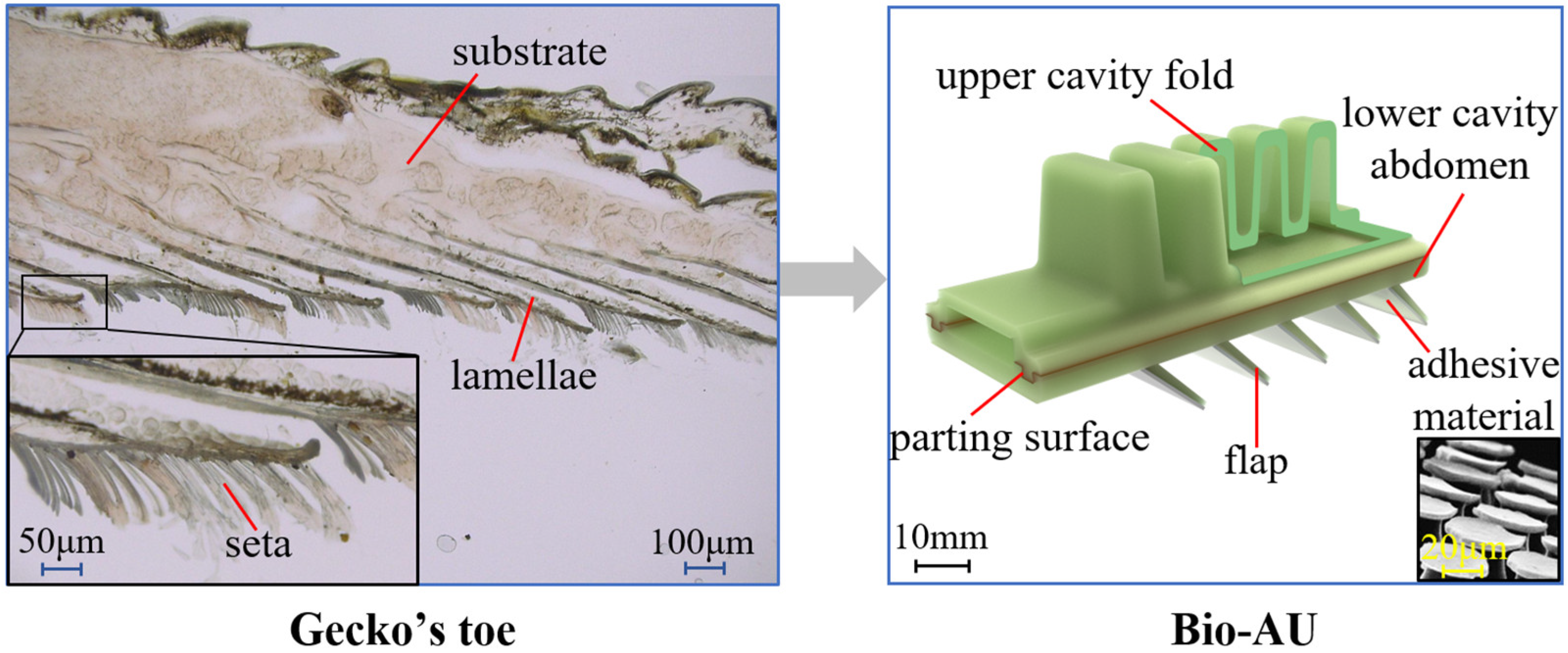
Figure 2.
Finite element analysis and corresponding results of plane models for three different parting structures (plane, right-angle tenon-and-mortise (RTM), and dovetail tenon-and-mortise (DTM)): (a) diagram of three parting structures; (b) finite element analysis of plane models for three parting structures under the same displacement (0.6 mm); (c) interfacial separation force; and (d) avulsion energy of three parting structures generated during interface separation.
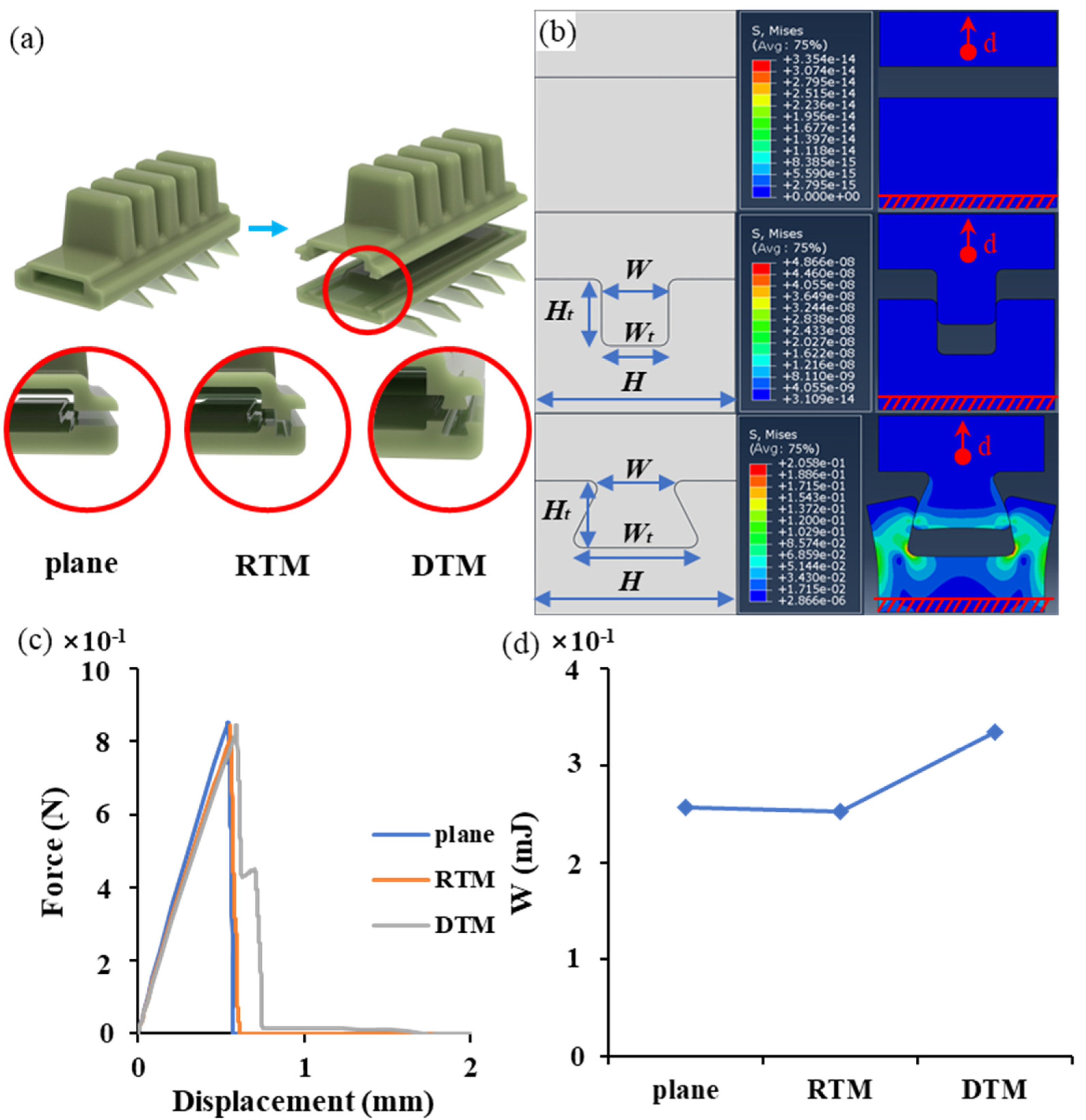
Figure 3.
Finite element analysis and corresponding results for plane models of nine DTM parting structures: (a) finite element analysis of plane models for different DTM parting structures under the same displacement (0.6 mm); (b) interfacial separation force of nine DTM parting structures generated during interface separation; and (c) avulsion energy of nine DTM parting structures generated during interface separation.

Figure 4.
Exploded and physical diagrams of mold: (a) upper cavity fold molds; (b) lower cavity abdomen molds (unembedded objects); (b’-1) first set of lower cavity abdomen molds (embedded objects); (b’-2) second set of lower cavity abdomen molds; and (c) flap molds.
Figure 4.
Exploded and physical diagrams of mold: (a) upper cavity fold molds; (b) lower cavity abdomen molds (unembedded objects); (b’-1) first set of lower cavity abdomen molds (embedded objects); (b’-2) second set of lower cavity abdomen molds; and (c) flap molds.
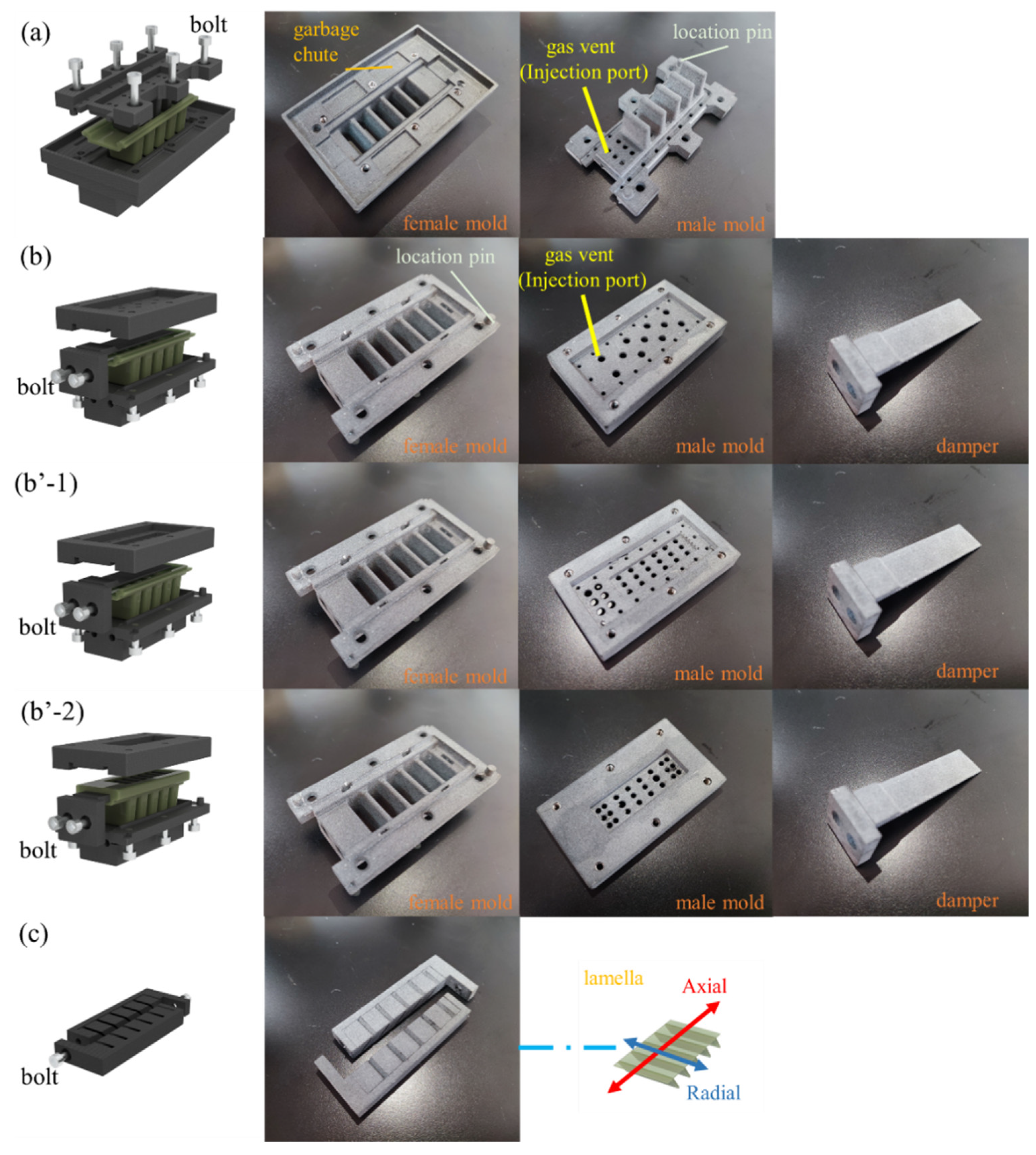
Figure 5.
Tensile test for elastic moduli of materials: (a) three component materials; (b) tensile testing machine; and (c) results of tensile test.
Figure 5.
Tensile test for elastic moduli of materials: (a) three component materials; (b) tensile testing machine; and (c) results of tensile test.
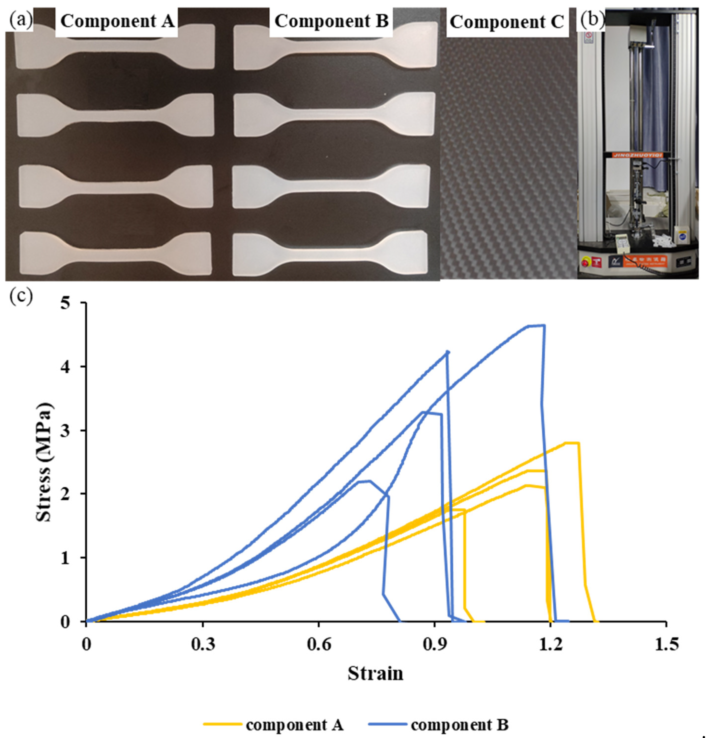
Figure 6.
Three fabrication processes: (a) lamination mold casting (“divided cavity molding-integrated assembly,” DCMA); (b) optimized lamination mold casting (“simultaneous molding and assembly,” SMA); and (c) stereolithography (SLA) 3D printing technology.
Figure 6.
Three fabrication processes: (a) lamination mold casting (“divided cavity molding-integrated assembly,” DCMA); (b) optimized lamination mold casting (“simultaneous molding and assembly,” SMA); and (c) stereolithography (SLA) 3D printing technology.
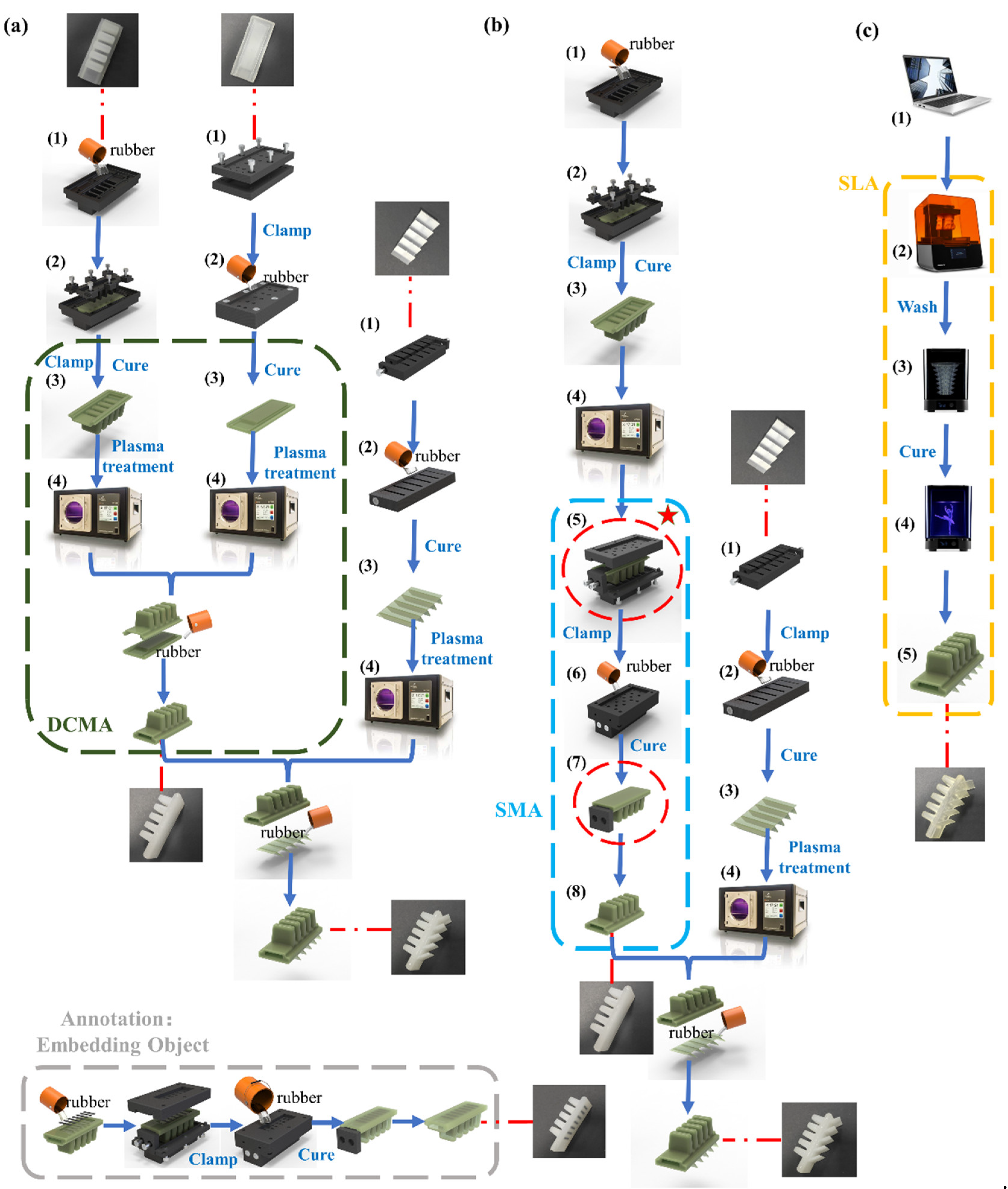
Figure 7.
Pneumatic drive system: (a) functional block diagram; and (b) physical connection diagram.
Figure 7.
Pneumatic drive system: (a) functional block diagram; and (b) physical connection diagram.
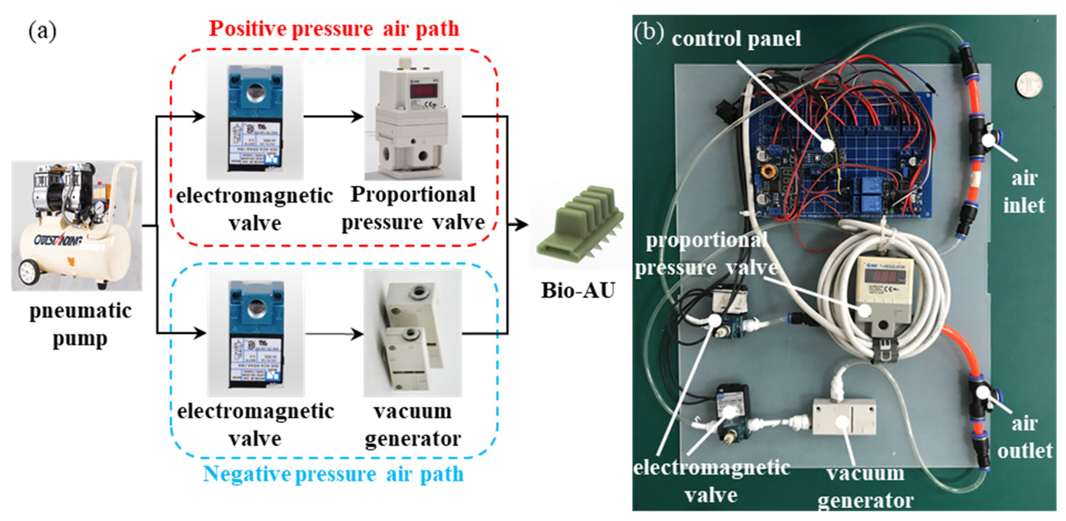
Figure 8.
Respective performances of Bio-AU samples fabricated via three processes: (a) comparison of bending performance and rupture failure of Bio-AU samples; (b) bending performance of Bio-AU samples; (c) box diagram of positive pressure-bearing ranges of Bio-AU samples; and (d) box diagram of negative pressure-bearing ranges of Bio-AU samples.
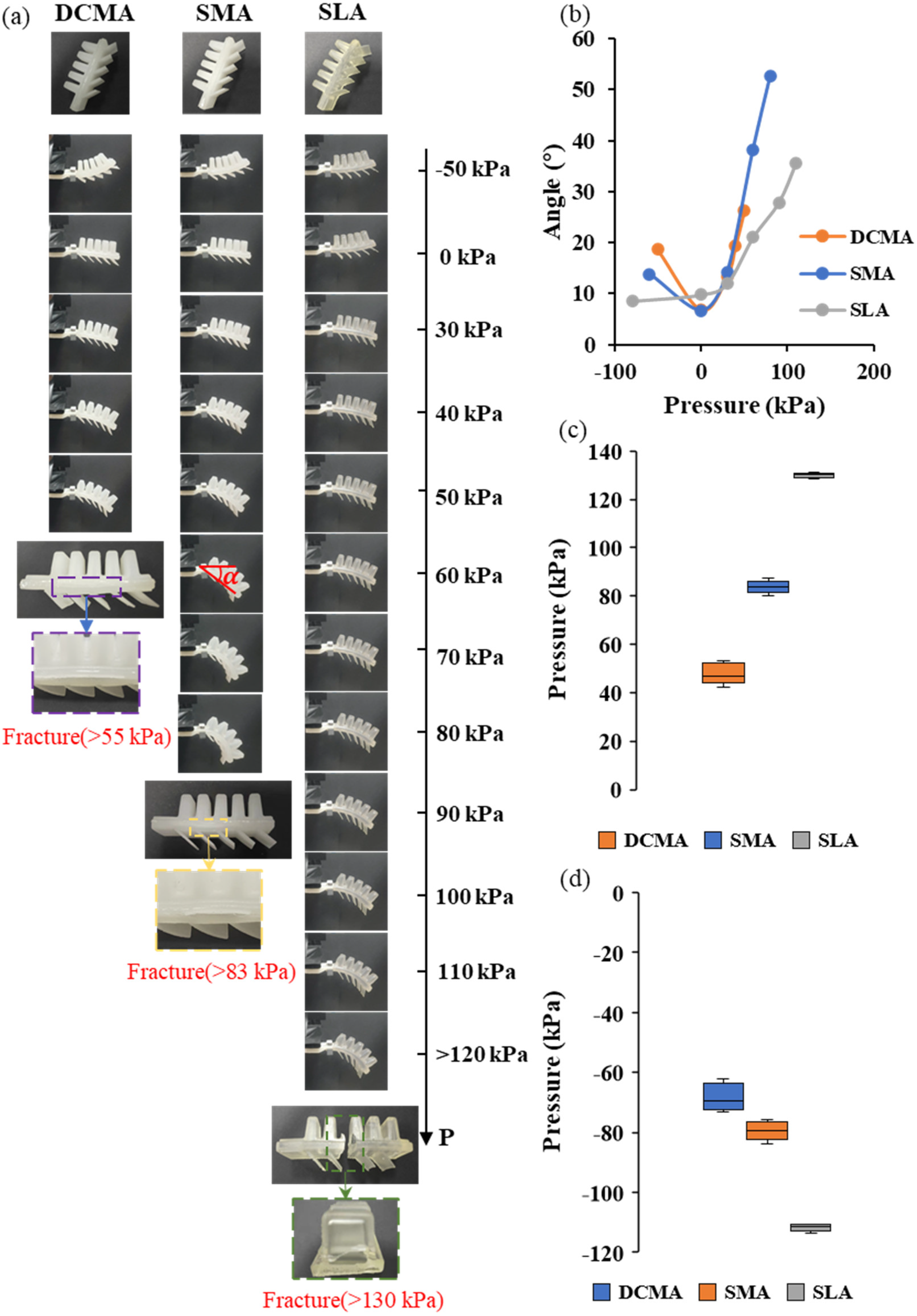
Figure 9.
Application of the Bio-AU: (a) flexible hand-pulled paper bag weighing 54 g; (b) coke weighing 482 g; and (c) snacks weighing 200 g.
Figure 9.
Application of the Bio-AU: (a) flexible hand-pulled paper bag weighing 54 g; (b) coke weighing 482 g; and (c) snacks weighing 200 g.

Table 1.
Orthogonal experiment method design.
| Test Number | Factors | Level Combination | ||
|---|---|---|---|---|
| I | 1 | 1 | 1 | |
| II | 1 | 2 | 2 | |
| III | 1 | 3 | 3 | |
| IV | 2 | 1 | 2 | |
| V | 2 | 2 | 3 | |
| VI | 2 | 3 | 1 | |
| VII | 3 | 1 | 3 | |
| VIII | 3 | 2 | 1 | |
| IX | 3 | 3 | 2 | |
Table 2.
Flexible gripper material composition.
| PDMS | Hardener | SiO2 | Ecoflex-A | Ecoflex-B | |
|---|---|---|---|---|---|
| Component A | 50% | 5% | 5% | 20% | 20% |
| Component B | 66.7% | 6.7% | 6.7% | 10% | 10% |
| Component C | carbon fiber board T700. | ||||
Publisher’s Note: MDPI stays neutral with regard to jurisdictional claims in published maps and institutional affiliations. |
© 2022 by the authors. Licensee MDPI, Basel, Switzerland. This article is an open access article distributed under the terms and conditions of the Creative Commons Attribution (CC BY) license (https://creativecommons.org/licenses/by/4.0/).
Share and Cite
MDPI and ACS Style
Zhang, L.; Wang, L.; Weng, Z.; Yuan, Q.; Ji, K.; Wang, Z. Fabrication of Flexible Multi-Cavity Bio-Inspired Adhesive Unit Using Laminated Mold Pouring. Machines 2022, 10, 184. https://doi.org/10.3390/machines10030184
AMA Style
Zhang L, Wang L, Weng Z, Yuan Q, Ji K, Wang Z. Fabrication of Flexible Multi-Cavity Bio-Inspired Adhesive Unit Using Laminated Mold Pouring. Machines. 2022; 10(3):184. https://doi.org/10.3390/machines10030184
Chicago/Turabian StyleZhang, Linghao, Liuwei Wang, Zhiyuan Weng, Qingsong Yuan, Keju Ji, and Zhouyi Wang. 2022. "Fabrication of Flexible Multi-Cavity Bio-Inspired Adhesive Unit Using Laminated Mold Pouring" Machines 10, no. 3: 184. https://doi.org/10.3390/machines10030184
Note that from the first issue of 2016, this journal uses article numbers instead of page numbers. See further details here.