
A Novel Modular Biomimetic Live Working Robot for Power Distribution Line †

1
Guangzhou Mechanical Engineering Research Institute Co., Ltd., Guangzhou 510530, China
2
School of Mechanical & Automotive Engineering, South China University of Technology, Guangzhou 510641, China
*
Author to whom correspondence should be addressed.
†
This paper is an extended version of our paper published in Zhang, Z.; Liao, D.; Guo, P. Design of a Live Work Climbing Robot Platform for the Distribution. In Proceedings of the 2021 China International Conference on Electricity Distribution (CICED), Shanghai, China, 7–9 April 2021; pp. 252–258.
Machines 2022, 10(3), 195; https://doi.org/10.3390/machines10030195
Submission received: 1 February 2022
/
Revised: 17 February 2022
/
Accepted: 2 March 2022
/
Published: 8 March 2022
(This article belongs to the Section Robotics, Mechatronics and Intelligent Machines)
Abstract
:Live working on power distribution lines is an effective way to improve the reliability of power supply. The aerial lift device with an insulated boom is often used as a platform to carry out live working, which is difficult to carry out in mountainous areas, paddy fields, and other complex environments. At the same time, power distribution live working requires highly skilled operators, and a lot of personal security measures, which is not conducive to the application in some developing countries. We imagine that the solution of the above problem is to use a robot to climb up the pole and complete the live working instead of the operator. In this article we report a low-cost modular biomimetic robot. The structure of the robot is designed to meet the requirements of live working, and the motion mechanism of the robot climbing poles and performing live work is analyzed. The feasibility of the technology is verified through simulation, experiments, and tests.
1. Introduction
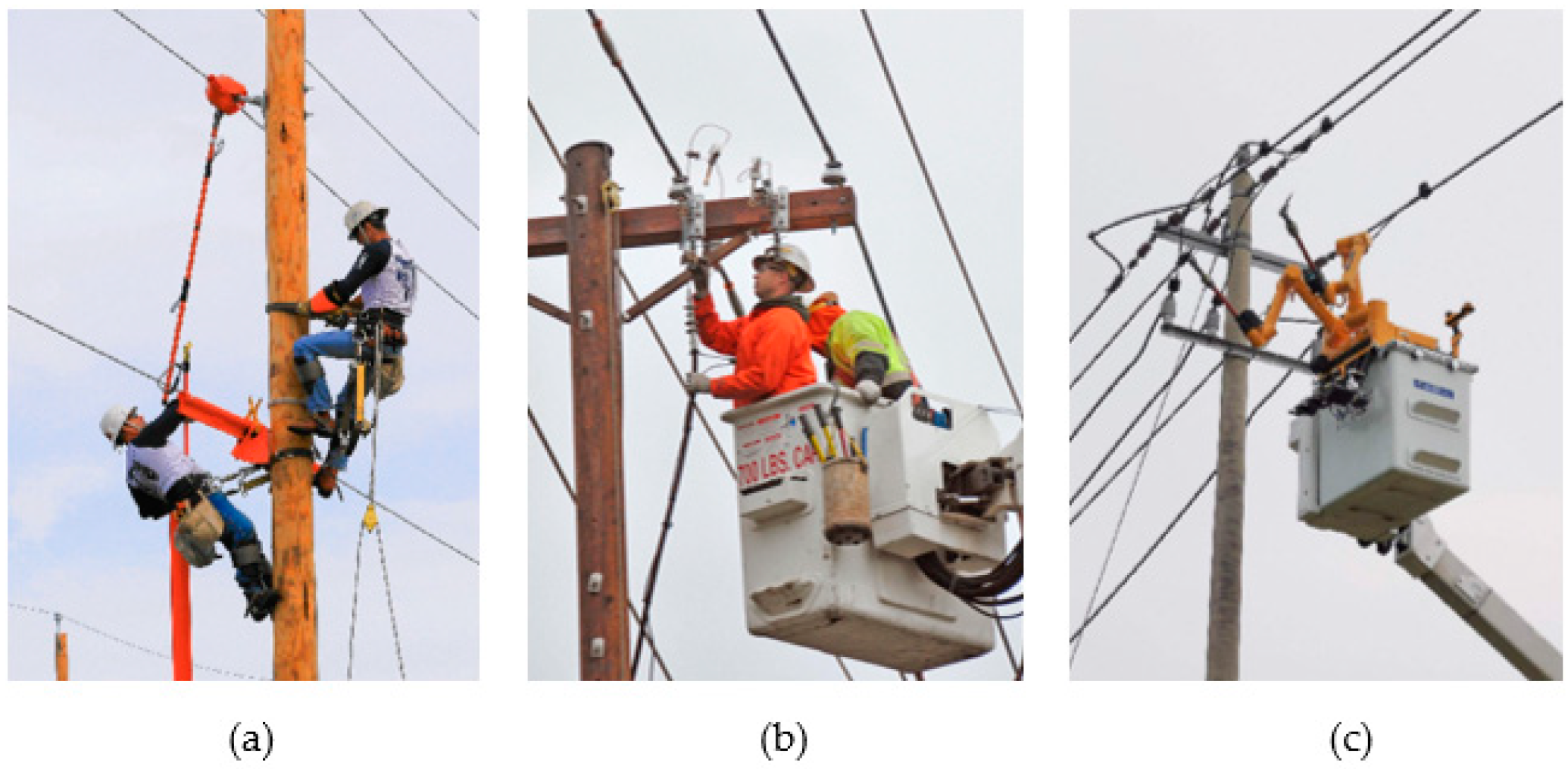
Overhead power distribution line is the main method of distribution and power supply in most countries and regions because of its low cost, simple and quick erection. Live working for power distribution lines is an effective way to improve power supply reliability. However, power distribution live working is often high altitude work, must solve the problem of insulation and safety, requires an expensive professional aerial lift device with an insulated bucket [1], and the operators also need to have professional skills of climbing and operation [2], as shown in Figure 1a,b. Therefore, power distribution lines live working is sometimes difficult to promote in developing countries. In addition, the environment is also an important factor to restrict live working, including mountains, paddy fields, and areas inaccessible to vehicles.
With the development of robotics and computer technology, many institutions want to use robots to do the live working, which will reduce the operation threshold and improve the intelligence level of the operation [3], as shown in Figure 1c. Live working robot researches have been conducted in North America, Japan, and Europe. These robots are mounted on the aerial lift device which is often expensive and does not solve the problem of flexibility [4].
Supposing that a robot can climb the pole by itself and overcome various obstacles on the pole, and then performs the live working job at high altitude, it is undoubted to reduce costs and improve the flexibility of live working [5,6].
There are already a range of climbing robotic researches and devices available. A multi-task 4 DoF (Degree of Freedom) pole climbing/manipulating robot was designed by Professor Tavakoli’s team which can move flexibly in a complex environment [7]. A self-calibrating method was proposed to measure the accumulating errors in the climbing process [8]. There are also researches that have presented design and control concepts for mobile robots that can walk around and perform several tasks over 3D terrain [9]. Climbing robots were already capable of climbing over 3D structures with bends and branches [10]. The merged concept to the design of leg mechanism and control was applied to walking robots [11]. The equilibrium state control of the humanoid climbing robot can be used in not only horizontal spaces but also in vertical spaces in mountain areas or other areas [12].
Biomimetic robots for the operation of electrical equipment are also increasingly mentioned, various prototypes of biomimetics are being established [13]. These biomimetic robots can reproduce biological behaviors of trunks, tentacles, or snakes [14]. Research on the kinematics model of biomimetic robots shows that the precision of rigid biomimetic manipulators has been greatly enhanced [15]. Most of the driving modules of climbing robots utilize multiple DC motors, whether wheeled or clamped [16]. The motor’s torque sensing method, along with the components and modularization method of the torque-controllable actuator unit are elucidated herein [17]. A modular robot was envisaged to climb on a pipe-like substrate and to change to another bar [18]. Guan’s team designed a modular biomimetic robot and carried out climbing and operating tests [19,20,21,22,23,24,25,26].
In reality, primates, insects, and amphibians all have the ability to crawl vertically in complex environments, but we prefer to simulate a creature that can crawl and work with a structure as simple as possible.
Based on the above researches, in particular, inspired by the modular robots that Guan’s team developed, a low-cost modular biomimetic power distribution live working robot was proposed in this article. First, the mechanical structure of the robot system is presented. Then, motion ability of robots under different operating environments and operating projects and the technical characteristics of the system are introduced. Finally, a live working biomimetic robot is built for the proposed system. The biomimetic body is both an operating arm and a climbing body. Simulation and experimental test results show that the proposed robot is suitable for climbing on a pole with obstacles and carrying out some live working projects.
2. Demand Analysis
Although experts and scholars of various countries have developed several climbing robots [5,6,7,8,9,10,11,12,13], in practical application, the power distribution live working robot system needs to have the following capabilities and functions:
- The live working robot needs to move in a certain space and change position at any time;
- The robot can replace the operator in dangerous environments, such as working at high altitude, close to live equipment;
- Some parts of the live working projects need long-term duty and repetitive work;
- Many live working operations need to be carried out in narrow spaces and complex environments, thus the robots must be light and flexible;
- The robot needs to be highly reliable, and at the same time, it is urgent to reduce cost and improve cost performance;
- The robot must be simple to operate, easy to control, and highly maintainable, to meet the needs of grassroots use.
In addition to the most basic climbing ability, the most important function of robots is the ability to carry out work, which is also the ability of many pole climbing robots neglected at present [13,14,15,16,17]. Some robots need to install an additional task module device on the climbing system to accomplish different tasks, such as a special end-effector or manipulator [3,4]. Therefore, it is still an important research direction of pole climbing robots to realize crawling and operating functions in one body [19,20,21].
Combining the characteristics of the clamped pole climbing robot and the biomimetic robot, the robot proposed here can directly climb up and down the cement pole or wooden pole, close to the conductor or charged body, and can carry out part of the power distribution living work project.
3. Design
3.1. Mechanical Structure
The biomimetic live working robot is inspired by the motion of inchworms. The inchworm has two rows of legs on its head and tail that can latch, stick, or suck onto objects to support its body, as shown in Figure 2a [18,19]. The movement and operation principle of the robot also comes from this. We imagine that the robot should be able to support the body through the end-effector on one side as the inchworm does, and find the new support point or work point on the other side like a manipulator.
The mechanical structure of the robot can be divided into two parts: biomimetic body and pole-climber, as illustrated in Figure 2b,c.
3.2. Biomimetic Body
The biomimetic body of the robot adopts modular design to imitate the body movement of the inchworm. Its mechanical structure can consist of three kinds of modules that are connected in series by clamping rings.
The different kinds of modules are 1-type module (axial movement, module appearance like “1”), 7-type module (normal movement module, module appearance like “7”), and 6-type module (the gripper, for memorization purposes). The robot adopts the modularity design, which can be decomposed into several modules. These modules are independent units, which can be combined freely according to the different applications. In Figure 3 the 1-type and 7-type modules are presented [20].
The 1-type module and 7-type module are composed of complex curved surfaces, which have two advantages. First, it can ensure that the whole robot body is the center of mass along one link axes, which can reduce the difficulty of robot control and improve the accuracy of control algorithms. Second, the smooth surface is less likely to cause tip discharge in the environment of strong electric field, and to touch or scratch other objects, thus more suitable for live working.
The revolute axis of the 7-type module is perpendicular to the link axes, and the revolute axis of the 1-type module is collinear with the link axes. While a 7-type module resembles the rotational motion of the human elbow or knee, the 1-type module resembles the rotational motion of the forelimb of the human arm, rotating around its axis [21].
The mechanical system of each module is similar and can be divided into control unit, power unit, transmission mechanism, and deceleration mechanism. The difference between the 1-type module and 7-type module is that the gear of the transmission mechanism changes the output direction of the movement [22].
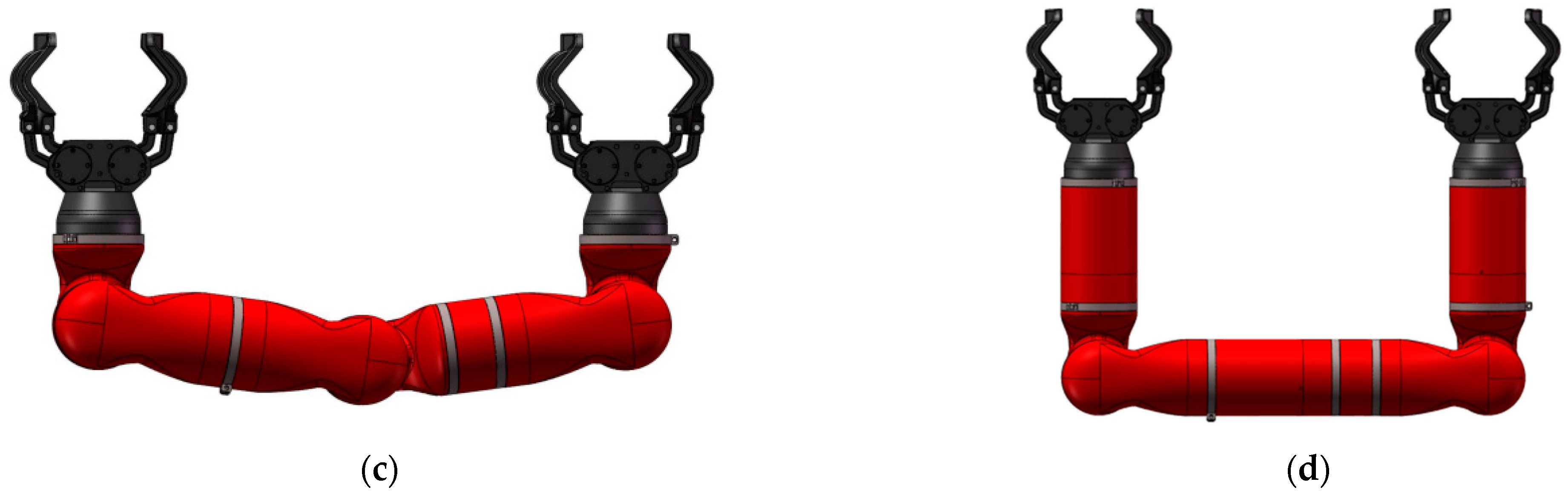
The biomimetic robots are designed to be symmetrical to achieve alternate climbing. For different scenarios and projects, the modular design of the robot can also achieve different configuration combinations to achieve different movement and performance requirements. Different configurations of robots made up of different modules are shown in Figure 4.
According to classical theory, at least 6 DoFs (short for degrees of freedom) are needed to reach any position in a 3D space. However, 5 DoFs are enough to allow the robot to climb on the poles, truss links, and tree trunks/branches, which are cylindrical, and the characteristic of alternating position of the robot can set up a feasible transition configuration on the trajectory that the robot can reach. For pole climbing, it is extremely important to reduce the weight and increase the load of the robot by reducing the degree of freedom [23].
In order to decrease the weight and the complexity of the structure, the biomimetic live working robot adopts the configuration shown in Figure 4a. The robot includes two 6-type modules, two 1-type modules, and three 7-type modules.
In order to distinguish different joint modules, the letters “a”, “b”, “c” are used after the module type to indicate the serial number of the module. The connection relationship between different kinds of joint module is as follows: 6a-1a⊥7a//7b//7c⊥1b-6b, the symbol “⊥” represents the vertical relation of the module axis between two adjacent modules, “‖” represents the parallel relation of the module axis between two adjacent modules, and “-“ represents the relatively fixed relation between two adjacent modules.
The gripper (6-type module) is used to fix the robot on an object, and can be utilized to grab other objects in the robotic system. The gripper consists of two clamp claw bodies, powered by a brushless motor. A set of worm gears is matched with the transmission mechanism of the gripper, which has a self-locking feature, to ensure safety and anti-falling.
The gripper is used to fetch the operation device, such as hot stick operation and instrument. When the hot stick tools are grasped by the clamp claw, collinear to the link axes and fixed tightly, the 1-type module can apply the rotating torque output to the hot stick tool.
Another function of the gripper is that it can be used to clamp the pole with diameter of 80–120 mm. Therefore, when the robot reaches the thinner pole section, the robot can also be transferred to the new operation area through the gripper. The gripper must be designed strong enough so that each gripper can withstand the total force which is generated by the robot weight and the motor’s reaction. For poles with larger diameters, a pole climber is required. The gripper was used to grasp the pole-climber as shown in Figure 5a.
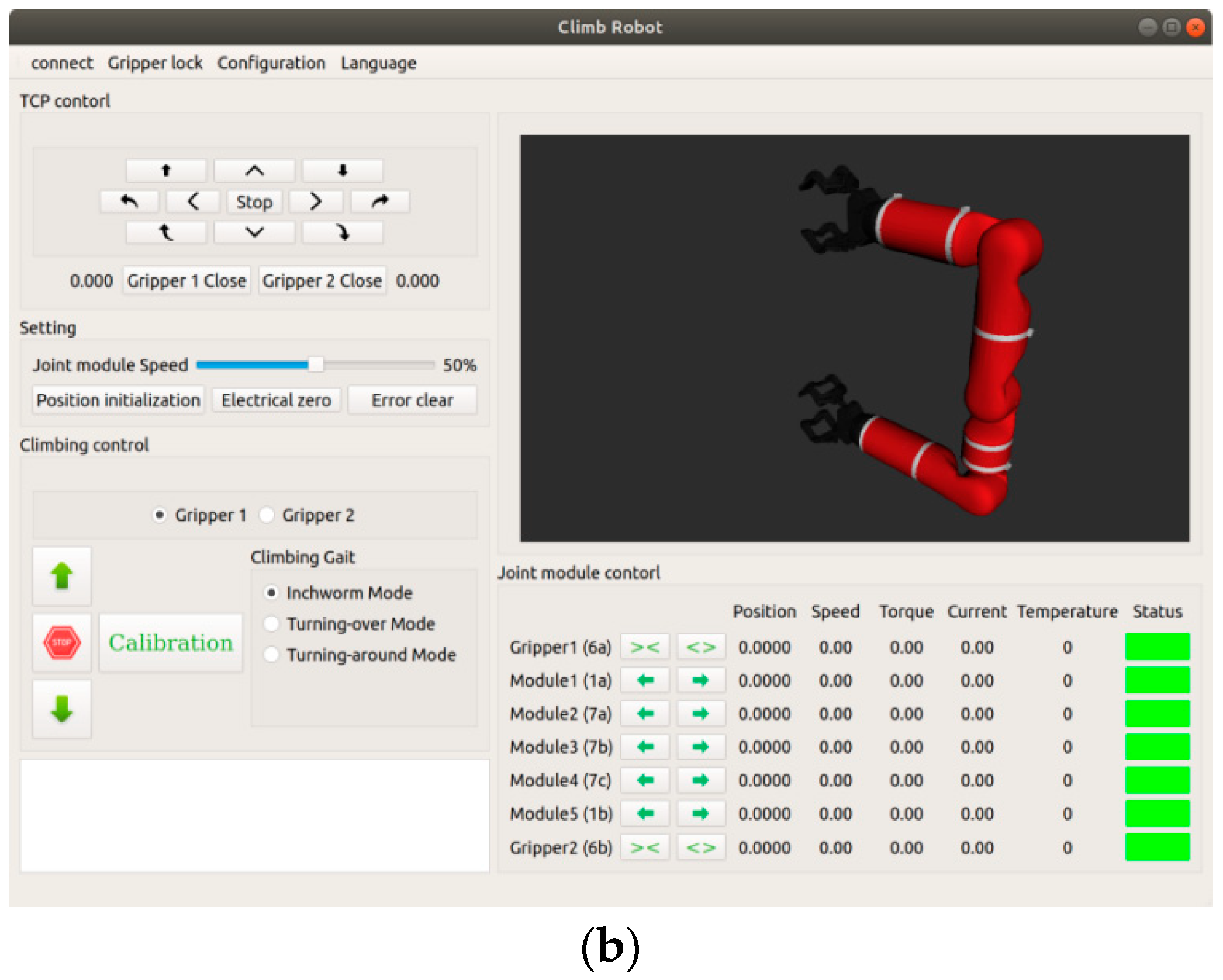
The robot can realize the automatic rod climbing function through teaching programming, and the operator directly controls the movements of the robot biomimetic body via the control interface, just like operating the mechanical arm. The control interface of the robot is given in Figure 5b.
3.3. Pole-Climber
In power distribution live working, the supporting object of the robot may be the pole, the cross arm, and the cable. A two-stage grasping system is proposed, as mentioned above, the gripper is used for grasping and operating, and another large gripper called the pole-climber, is used for holding the pole.
When the pole-climber is fixing the robot on the pole, it can also be a stable platform for the live working. At this moment, the pole-climber is a fixed fulcrum to realize lifting of tools. Consider the limited load of the robot, the weight of the pole-climber should be as little as possible.
The pole-climber is similar to the hook design of human pole climbing operation, including the triangular steel pipe for pole profiling, pipe sleeve, and profiling for small gripper grasping, and a push rod linear motor, which is illustrated in Figure 6. The driving mechanism of the triangular steel pipe and tube sleeve adopts a push linear rod motor, which can ensure self-locking in any case and anti-falling.
The pole-climber is controlled by a linear push rod motor to realize gravity self-locking and unlocking. A profile model for the small gripper to grab is installed at the back of the pole-climber, which can cause the small gripper to clamp firmly, as shown in Figure 7.
Considering the surface protection of the profile modeling, rubber cushions must also be installed rather than direct contact to increase the contact area between the gripper and the profile modeling.
3.4. Electrical and Control System
Motors and motor drivers are the key components of the robot, which are directly related to the motion performance and operational safety of the robot. Considering the influence of the overall structure size and driving load, the brushless motor is used in the design. The rated power is 150 W, the maximum continuous output current is 3 A, the peak current is 7 A, the maximum continuous output load is about 150 Nm, and the maximum speed can reach 3000 r/min.
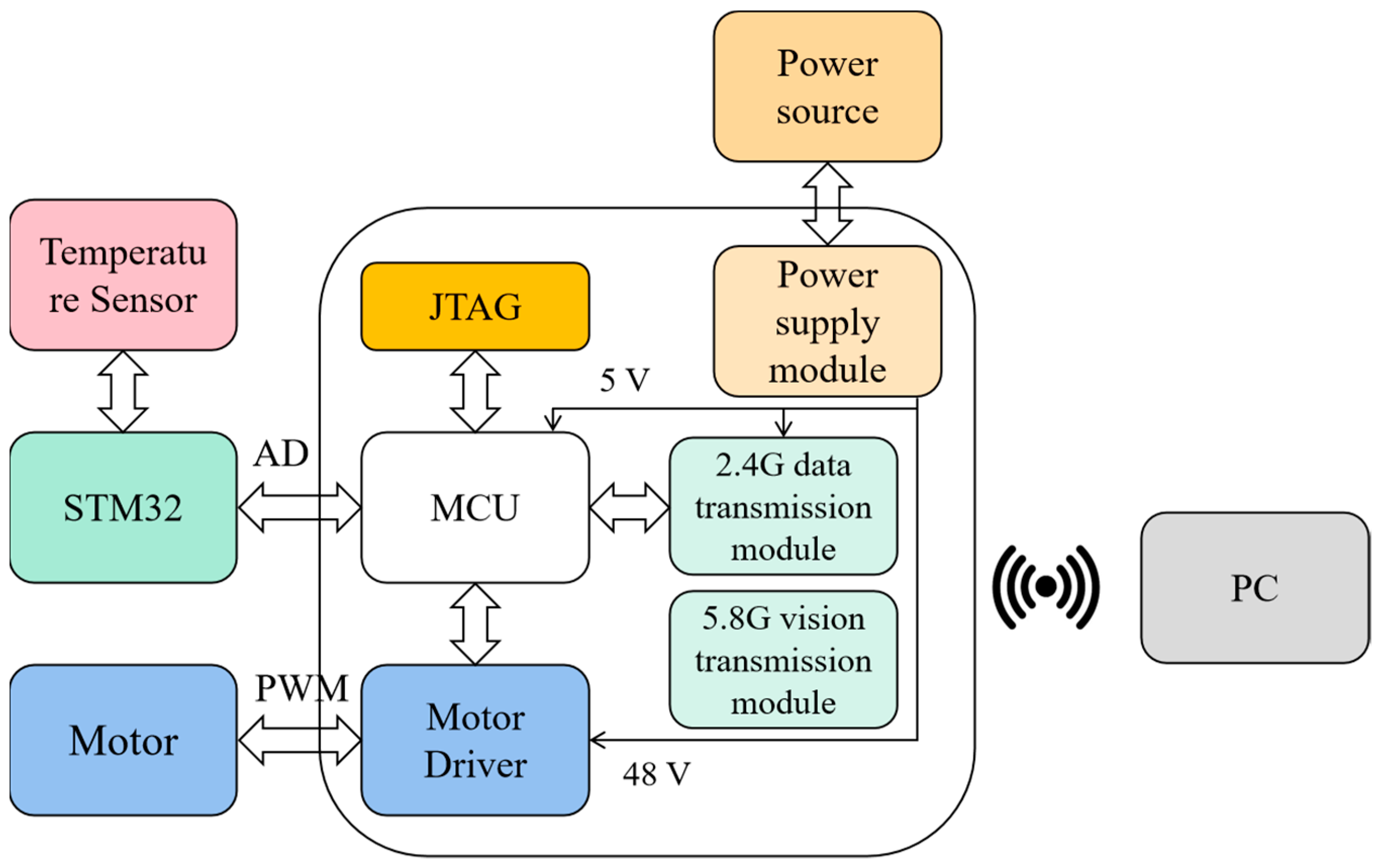
The MCU detects the current, angle, and torque of the motors in real-time through the encoder to obtain the accurate motion position of the robot, and then drives the motor to perform the corresponding climbing and operating motion. The ground control terminal (PC) of the wireless communication system interacts with the robot. In addition, the vision acquisition system can also obtain the robot’s motion position and the operation condition in real-time.
A PC running Microsoft Windows operating system is employed, which can complete the functions of joystick input data processing, motion planning, state monitoring, analysis of collected data, and camera image display. The servo layer is responsible for the accurate completion of the motion instructions sent by the upper computer. The driving layer provides the corresponding size current to the motor according to the PWM instruction, as shown in Figure 8.
The working environment of the robot often exceeds 40 °C. Affected by the sunlight, the temperature of the surface of the robot structure can reach 60 °C.
In the operation process, each motor will also produce a lot of heat. To avoid damage of the core components of the robot caused by heat, the temperature is a key parameter to monitor the operating state of the robot.
A set of multi-linked temperature monitoring systems is designed for the robot, which is based on the STM32 development board. The temperature measured by the thermistor sensor is compared with the environment temperature, and the operator can judge the running state of the robot in real time through the temperature data.
The primary control interface of the robot (as shown in Figure 5b) is developed in C++ and Python environments. The underlying motion control adopts ROS (the robot operating system) for analysis and calculation to form a unified action control platform [24].
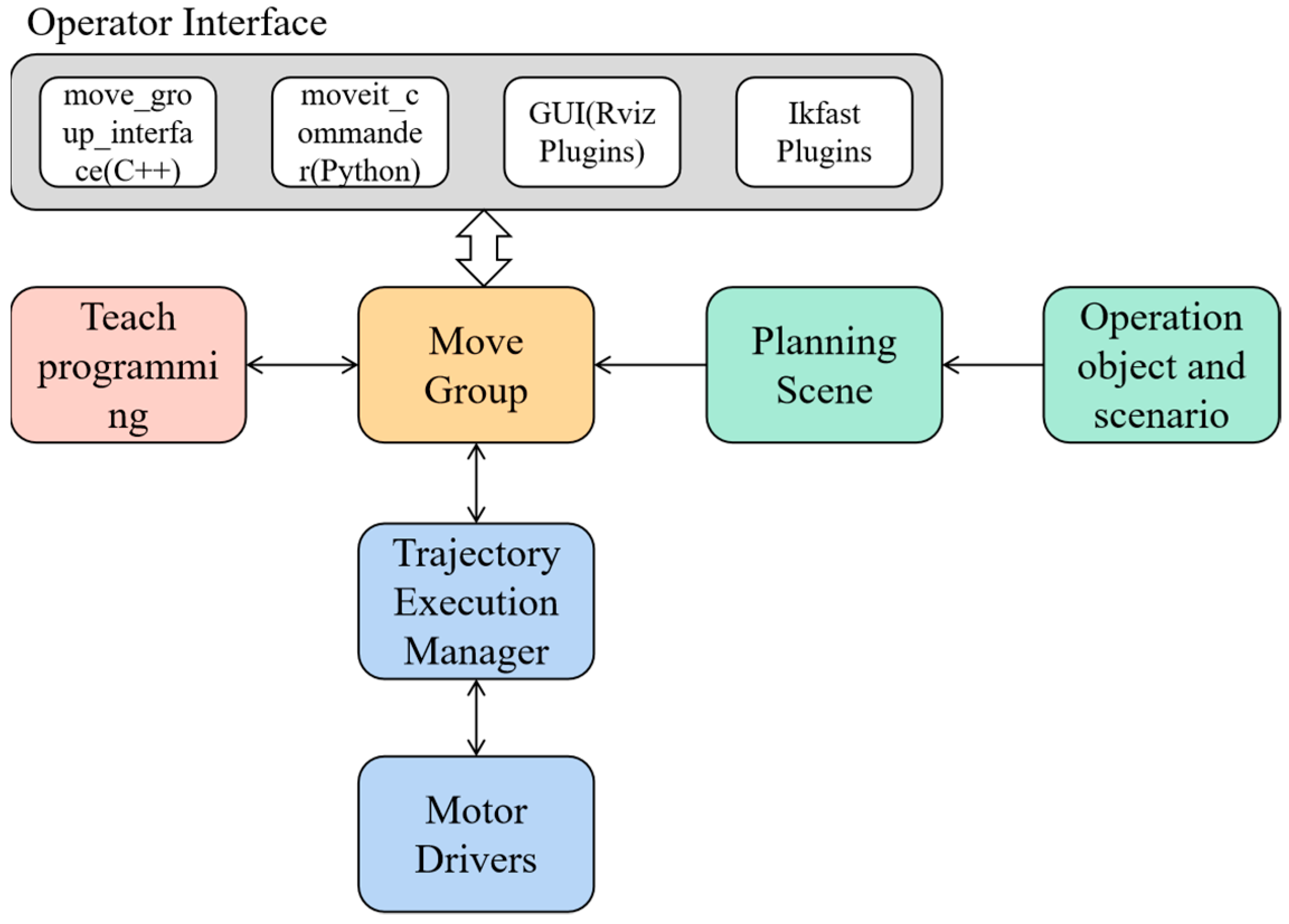
The open source MoveIt! Motion Planning Framework and the robot kinematics compiler IKFast were used for robot motion and path planning, the system architecture is shown in Figure 9.
Robot motion control can be divided into position mode and velocity mode. After the motion parameters of each joint are given in UDRF (Unified Robot Description Format) files, the fundamental chain of transformations that compute the end effector link frame is defined by:
where Ti is a constant affine transformation, and Ji is a transformation depending on joint value ji, which can be a rotation around an arbitrary axis vi:
or a translation along an axis:
For the inverse kinematics of the robot, IKFast was used to solve the equations analytically and generates optimized C++ files. IKFast differs in the other approaches in that numerical stability was emphasized over solution generality [25]. It is convenient to realize 5-axis coordinated action control.
4. Climb Pole
Depending on its kinematic structure, the robot can use a variety of climbing methods. For simplicity, we assume that the poles are perpendicular to the ground and the robot moves in free space. Three kinds of climbing gaits are proposed based on the assumption that the robot is supported by both pole-climbers holding the support pole at the beginning [22].
4.1. Inchworm Gait
As shown in Figure 10, the robot follows these steps.
- Release the pole-climber (P2) and the robot is supported only by the other pole-climber (P1) which grasps the pole firmly, the robot rotates three 7-type modules to move the released pole-climber (P2) to a higher target position on the pole (refer to Figure 10a,b,e,f);
- The pole-climber P2 is closed to grasp the pole firmly, and pole-climber P1 is released (see Figure 10c,g);
- Supported only by the new fulcrum fixed by pole-climber P2, the robot rotates three 7-type modules so that P1 moves towards a new target position on the pole (see Figure 10d,h);
- Pole-climber P1 firmly grasps the pole so that P1 can support the robot;
- Repeat the above steps.
In this gait, the 1-type modules may be useless so that the robot moves in a plane without the requirement for transitions between different poles or links. The 7-type module is the main output, three 7-type modules cooperate to achieve upward peristalsis, the pole-climber has no need to pull out from the pole. The different modules’ torque waveforms of inchworm gait are shown in Figure 11. The space requirement of gait is small.
The roles (opening and closing) of the two pole-climbers change in turn. Although the step length of each step is limited, the overall safety is very good.
The step length of inchworm gait is
where l1 is the link length between two adjacent 7-type modules and a is the module angle in both directions, as shown in Figure 10f [23].
When the robot moves on the pole, perpendicular to the ground, in inchworm gait, the action range of each axis is minimum, and the output load of the motor can also be controlled at the minimum, which can realize the maximum load output of the robot as a whole. However, the cost of inchworm gait is to sacrifice the overall obstacle surmounting ability of the robot.
4.2. Turning-Around Gait
As shown in Figure 12, the climbing gait steps can be listed as follows.
- Release the pole-climber (P2) and supported only by the other one (P1) which grasps the pole firmly (Figure 12a,e);
- The robot rotates 1-type (1a) modules to move the pole-climber (P2) away from the pole, and rotates by 180° (Figure 12b,c,f,g);
- The robot rotates 7-type modules to move the swinging pole-climber P2 towards the target position for grasping the pole (Figure 12d,h);
- Pole-climber P2 closes to grasp the pole. Thus, the robot is supported by both grippers.
- Repeat the above steps.
In this gait, the 1-type module produces the most effort in this gait. Larger spaces are required on both sides to climb. The maximum step length with this gait is smax = 2l1 [23].
Turning-around gait, simulating a human operator using the hook climbing pole action as utilized in many countries or regions, alternating up switch fulcrum, mainly through the 1-axis motor for torque output, The different modules’ torque waveforms of turning-around gait are shown in Figure 13. This gait has a good passability for obstacles perpendicular to the robot action surface.
4.3. Turning-Over Gait
The procedure is shown in Figure 14 and stated as follows.
- Release the pole-climber (P2) and supported only by the other one (P1) which grasps the pole firmly, the robot rotates 7-type and 1-type modules in order to pull the pole-climber (P2) away from the pole (Figure 14b,f);
- The robot continues to rotate 7-type modules. As a result, the whole robot turns over (Figure 14b,c,e,f);
- The robot continues to rotate 7-type and 1-type modules to push the swinging pole-climber P2 to the target position on the pole for grasping (Figure 14d,h);
- The pole-climber P2 closes to grasp the pole, thus the robot is supported by both pole-climbers.
- Repeat the above steps.
Similar to the inchworm gait, the 7-type modules produce the most effort in this gait, the 1-type modules only play an auxiliary role when the pole-climber is detached from the pole. The different modules’ torque waveforms of turning-over gait are shown in Figure 15. The robot moves in a plane, but the space of turning-over gait is much bigger than the inchworm gait. The maximum step length with this gait is smax = 2l1 [23].
The motion range of the turning-over gait is the largest, and it needs coordination between three 7-axes to achieve, thus the turning-over gait has the best passability for the obstacles in the robot’s motion plane. At the same time, the robot often needs the action combination of this gait to get close to the working position for the working target located on its side.
The penetration of the turning-over gait is very useful in the limited space of most multi-circuit lines on the same pole.
4.4. Overcoming Obstacles
Overcome obstacles performance of robot comes from its ability to move in a 3D space. In particular, the turning-around gait and turning-over gait can achieve stepping over an obstacle. The feature can be analyzed by the geometric figure, which is illustrated in Figure 16. The relationship between the height, h, and width, w, of the cube obstacle that the robot can overcome is
Because of the modular design of the robot, the parameters of l0, l1, R, and d were adjustable from the aforementioned formula [22]. Different sizes of joint modules were needed to customize.
4.5. Gait Comparison
As mentioned earlier, each climbing gait has its own characteristics. The comparison of these features is listed in Table 1, where the key modules are those that produce the most effort during the climb. With these gaits, or a combination of them, the robot can navigate in all directions between flat, smooth, continuous, or discrete poles, and navigate a wide variety of obstacles. The turning-over gait may be not found in animal climbing, but the turning-around gait is very similar to climbing pole action of human legs. Because of the different structure and kinematics configuration of the robot, the mobility of the robot can be greatly improved [19,20,21,22,23].
For an ideal cylinder, the three gaits can be realized to automatically climb the pole by teaching programming.
Due to the different directions of the pole-climber opening and the safety considerations, it is recommended to use the turning-around gait when using the pole-climber. The action coordination steps of pole-climber pull out from the pole can be reduced effectively.
For obstacles and other uncertain factors encountered in pole climbing in reality, simple image recognition and human-machine cooperative operation are recommended to complete pole climbing. The description will not be expanded here.
4.6. Safety Analysis
As shown before, the small gripper and the pole-climber can be used to grasp the cement pole both.
Eight buffer pads and eight FSR pressure sensors are installed inside the small gripper, respectively. When the small gripper is closed, FSR measures the pressure value. The clamping strength between the small gripper and the pole can be judged by calculating the value of the pressure sensor [26].
4.6.1. Grasping Force Analysis
When holding the cylinder, it is connected with four lines, the eight measured values are set as f1n, f2n, f3n, f4n, f1m, f2m, f3m, f4m, as shown in Figure 17a.
In the beginning, the gripper grasps the object without any of the robot’s gravity, as shown in Figure 17a. At this stage, only the balance between the grasping force and the reaction force should be considered. The values of f1n, f2n, f3n, and f4n measured by each pressure sensor should be close, and f1n ≈ f1m, f2n ≈ f2m, f3n ≈ f3m, and f4n ≈ f4m, the difference between the two values, should not be greater than the setting value ∆ftn.
In the second stage, the load is generated when the gripper becomes the fulcrum of robot. The end of the gripper tilts at a certain angle due to the load generated by the robot’s gravity. During tilting, the gripper can achieve self-lock, creating a large reaction force that prevents the gripper from opening outward.
f1n′ < f1m′, f2n′ > f2m′, f3n′ < f3m′, and f4n′ > f4m′ should be measured at this stage, and the difference between the different sensors of each group should be greater than the setting value ∆ftn′.
The robot gravity produces a self-locking effect, thus, as long as the gripper stays closed, it can ensure that the robot is fixed on the pole with anti-falling.
As shown in Figure 18, when the gripper clamps on the profile model, it is affected by the gravity of the robot, f1n < f1t1, f2n > f2t1, f3n < f3t1, and f4n > f4t1 were measured. The measured value can be used to judge whether the gripper grasps the profile model.
4.6.2. Self-Locking Performance Analysis
The pole-climber makes use of the gravity self-locking principle, with the help of the weight of the robot body, so that the other side is closely buckled onto the pole, resulting in greater friction, to fix the pole easily; in the process of climbing up, the robot and the pole-climber push rod linear motor cooperate to achieve automatic release of the buckle—using the phenomenon of self-locking in mechanics. If the action line of the net force Q acting on the main force of the object is within the friction angle, no matter how large the force is, there is always an all-reaction force R in balance with it, and the object remains at rest. Conversely, if the action line of the resultant force Q is outside the friction angle, no matter how small the force is, the body cannot maintain balance, as shown in Figure 19.
It is not necessary to install FSR on the pole-climber because of its self-locking features.
For different countries or regions, different materials are used for electric poles. For wooden poles, the clasp ring has iron teeth, and for cement poles, the clasp ring is wrapped with rubber pads and an anti-slip block.
5. Operation
5.1. Operation Process
The operation process of the biomimetic power distribution live working robot can be listed as follow:
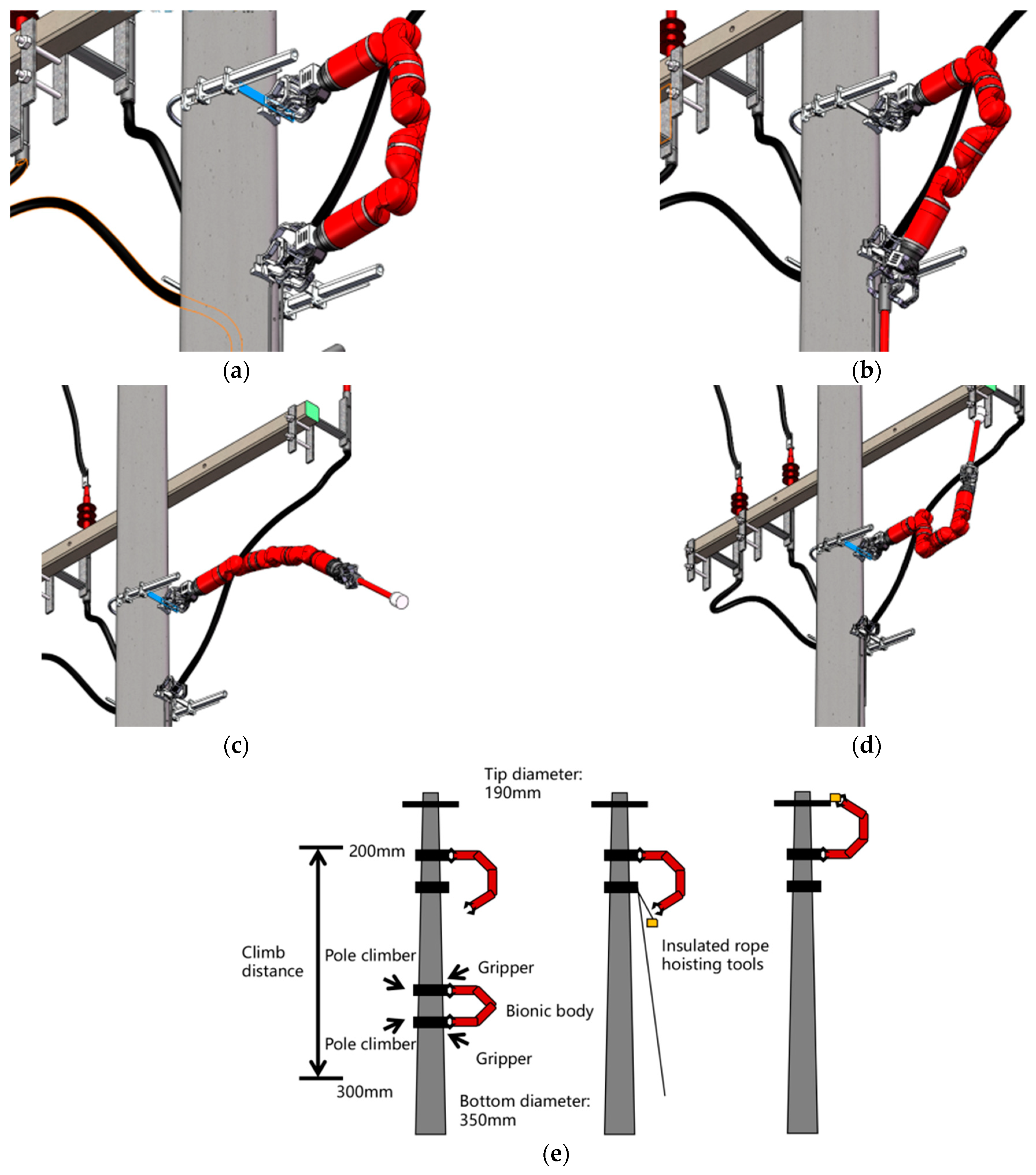
- The robot grasps the pole from a height close to the ground through the pole-climber, and climbs up alternately with both pole-climbers, as shown in Figure 20a. During the process of climbing the pole, the mechanical arm climbs up alternately, which is automatically controlled by the program.
- According to the characteristics of the device on the pole, it can use different gaits to overcome different kinds of obstacles.
- When the robot reaches the position near the operation objects, the small gripper below is released and grabs the lifting tool downward, while the pole-climber remains in its original position, as shown in Figure 20b.
- The robot enters the working position upward through valving or side rotation, as shown in Figure 20c.
- At this time, the operator controls the robot’s action posture through the rocker to start the operation, as shown in Figure 20d.
The plan sketch of operation process is shown in Figure 20e.
5.2. Operation Position
Safety specification for live working on power distribution lines varies in different countries and regions. For the sake of unity, the live working robot adopts the ground potential operation mode, that is, the robot and the charged body are isolated by an insulating rod or an isolator, and the robot body is fixed on the pole, which is regarded as connected to the ground.
Due to the different voltage levels, the phase spacing of overhead power distribution lines in various countries is roughly between 0.35 and 1.3 m. After proper path and motion planning, in most cases, the robot can crawl to a proper position to operate the three-phase line [29].
- Horizontal arrangement
For vertically aligned lines, the robot needs to take the middle phase conductor as the reference point and find a suitable position, approaching the wire from the side or below the side, as shown in Figure 21a.
- Triangle and vertically arrangement
For the triangulated and horizontal lines, the robot only needs to climb directly below the middle phase of the wire, and the two side phases of the wire only need to complete the work through the robot’s action, as shown in Figure 21b.
- Multi-circuit line on the same pole
For multi-circuit lines with the same rod, under the condition of up-down three-phase arrangement, the current robot action can directly carry out operations on the lower-three-phase line. After insulation treatment, the robot climbs through the lower-three-phase wire and approaches the third-up phase line to carry out operations.
In the case of the left and right phases, the vertical alignment line can be referred to. The robot needs to take the middle phase conductor as the reference point and find a suitable position, and approaches the side wire from the side or below, as shown in Figure 21c. It is worth pointing out that the space of the multi-circuit line with the same pole is limited, so it is necessary to pay attention to the robot’s movement accuracy and avoid touching the live equipment [30].
5.3. Operation Project
The robot mainly works by contacting the charged body with hot stick tools. Depending on the actual situation of overhead power distribution equipment in different countries and regions, different kinds of hot stick tools have been developed around the world. After simple improvement, they can be quickly transplanted to the robot. These hot stick tools can be driven by their own motors or powered by the end 1-type module of the robot.
The motion steps of robot operation can be simplified into the combination of four motions: aiming, grasping, touching, and releasing, as shown in Figure 22.
In this series of motions, each joint module plays a different role. As Figure 22 shows, the 1a joint module rotates to adjust the biomimetic robot body direction, and the 7a, 7b, and 7c joint modules cooperate to approach or stay away from the operation target. The 1b joint module can be used to provide output torque for end hot stick tools.
- Verification of live parts and grounding
Verification of live parts and grounding are the basic safety measures before the maintenance of electric equipment. The steps are quite simple, which can be completed through the simple combination of the above aiming and touching motions.
It is of great practical significance to use the robot to carry out verification of the live part and grounding by climbing the height, which can prevent personnel working at height and approaching live equipment.
- Elimination of defects and obstacles
As the biomimetic robot can provide a torque output of 150 Nm, it can grab saw blades, hydraulic scissors, and other tools through the small gripper to clean up floating hanging objects and tree barriers attached to the distribution line.
- Install fault indicator
Installation of fault indicators is a simple but huge workload project because it needs to be installed on the three-phase line near each base pole of the distribution line. By using robots for installation, this work can be quickly carried out.
After reaching the operation position, the robot determines the installation position by aiming, grasping the installation tool and touching the wire, and finally releasing, which is a classic operation motion, as shown in Figure 22.
- Equipment monitoring
When the robot climbs on high equipment, such as poles, towers, and post insulators, the robot can observe and detect the damage to the equipment in detail at close proximity, understand the equipment breakage, corrosion, and other conditions, and provide an auxiliary decision basis for the repair and maintenance of the equipment.
- Install and remove equipment leads or jumpers
It is perhaps the most common power distribution live working project, but also a very critical part of many complex projects. The method of connecting wire and wire clamp vary greatly from country to country, which may require the cooperation of two machines to complete part of the project.
- Replace the arrester
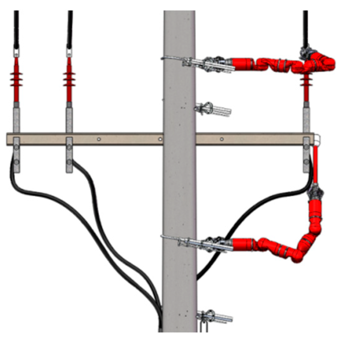
Similar to installing and removing equipment leads or jumpers, replacing the arrester requires coordinated operations of two biomimetic robots, no. 1 robot first removes the arrester high voltage lead, no. 2 robot removes the arrester grounding lead, no. 1 robot grasps the arrester, no. 2 robot removes the arrester fixed bolt, as shown in Figure 23, no. 1 robot will remove the arrester into the insulating rope bag, and then grasps a new arrester fixed on the bracket, no. 2 robot installs the arrester fixed bolt. Finally, no. 1 robot and no. 2 robot re-install the high voltage lead and the ground lead of the arrester, respectively [31].
6. Technical Characteristics
The robot adopts a self-locking design, under any circumstances, ensuring that it will not fall, thus, a high safety factor. Since the robot biomimetic body is both a crawler and an operation arm, in many operation scenarios, multiple robots can be moved to a specified operation station to carry out collaborative operations, which can effectively improve operation efficiency and cover more operation projects [32].
The total weight of the robot is no more than 25 kg (including power supply and controller), and the robot adopts modular design, which is easy to assemble and decompose, and the whole equipment can be carried by one man and carry out operations given by two people (operator and assist operator).
The mechanical structure of the robot is simple, a large number of non-bearing parts adopt 3D printing technology. Easy to disassemble and assemble, for damaged and faulty parts, and can realize quick replacement operation.
The load-bearing components of the robot body can be made of different materials, including aluminum alloy, stainless steel, carbon fiber, and other composite materials. The technological accuracy of metal parts only needs CNC (computer numerical control machine tools) processing, and the composite materials only need one mold opening to be mass-produced.
The motor, reducer, driver, and other parts are highly matured industrial products, and the hardware cost of a full set of robots has been greatly reduced. Robots can be used as low-value and consumable equipment to enter the work team. With the imagination of the experienced living work team staff, more work projects can be carried out to achieve further breakthroughs in functions [33].
7. Simulation, Tests and Results
A series of simulations and tests are carried out on the biomimetic power distribution live working robot in order to verify the key parameters of the proposed robot system and demonstrate its operational capability.
7.1. Robot Structure Simulation
Robot structural parts, including 1-type module and 7-type module bearing parts, have shown by force simulation analysis, that several different kinds of materials including: aluminum alloy, stainless steel, carbon fiber, and other composite materials can meet the strength requirements of power distribution live working load. The simulation results are shown in Figure 24.
7.2. Gripper Simulation
The grasping performance of different objects is tested. The grasping load test results show that the grasping force of 400 N can reach the grasping requirements of 40 kg load within the working range of the grasping device. Force analysis shows that the grasping force of 400 N will not damage the small gripper, as shown in Figure 25.
7.3. Motion Range Tests
When each module of the robot is fully expanded, the working radius that the robot can move to is the longest working radius. Make all modules shrink to the shortest radius; The working radius of the robot is tested by laser tracker.
The robot was controlled to run at the rated speed, and to make the mechanical claw run in a straight line to the fixed points P1, P2, P3, and P4, stable for 3 s. The laser tracker was used to record the spatial position of each point, and the cycle was repeated 30 times to measure the position repeatability. The robot can be regarded as a 5-axis manipulator fixed on a rod, as shown in Figure 27, the test values are shown in Table 3 and Table 4.
7.4. Climbing Speed Tests
7.5. Climbing Tests
The robot can move up and down flexibly by using the pole-climber in all three gaits on a cement pole perpendicular to the ground. As the limitation of the step length during the climbing process, the robot needs to adjust the climbing height to approach the conductor, to reach the required working position.
The test of robot pole climbing through the pole-climber and the small gripper is shown in Figure 29.
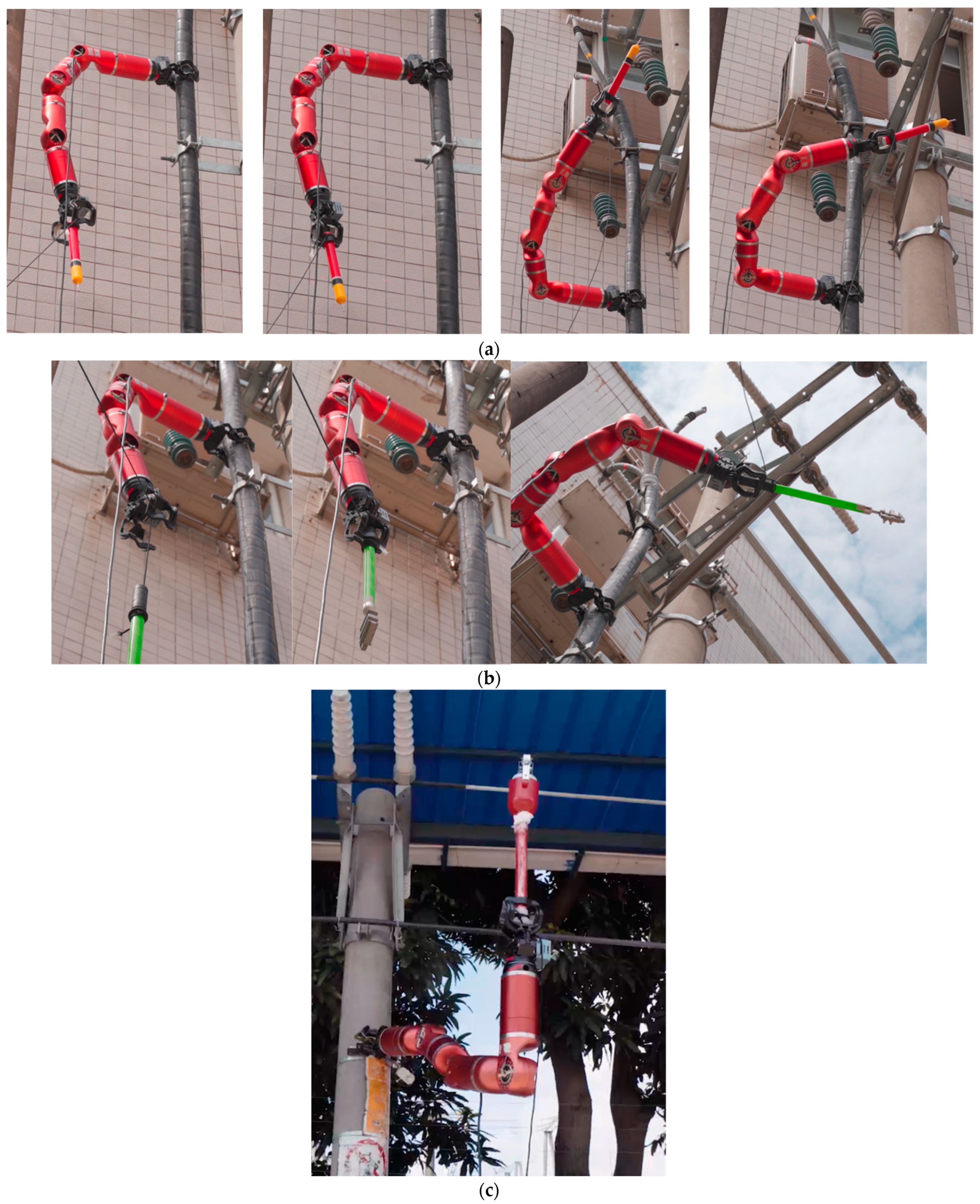
7.6. Operation Tests
After the robot reaches an appropriate work position, the end gripper can grab different insulating rod tools, and carry out corresponding live working on different kinds of equipment, as shown in Figure 30.
8. Conclusions
In this article, a new biomimetic power distribution live working robot was proposed. The robot characteristics demonstrated in simulations and experiments make the application of this technology attractive for live working.
The climbing and operating parts are integrated into one body. Achieving the flexibility and rapidity of pole climbing. A two-stage grasping system is proposed to meet the requirements of eliminating the difference of grasping objects in live working.
The total mass of the system composing the biomimetic body, pole-climber, gripper, and transmission mechanism was less than 25 kg, which can be carried by a single person. The operators control the system from the ground, the robot can climb up to a height of 10–20 m to carry out power distribution live working projects.
In mountainous areas, paddy fields, and other complex environments, the conventional aerial lift device cannot be extended, and the biomimetic power distribution live working robot can be used instead. Due to the use of robots, existing safety measures for operators of live working can be greatly simplified, which also improves live working efficiency significantly.
For different scenarios and projects, the modular design of the robot can also achieve different configuration combinations to achieve different movement and performance requirements. The biomimetic structure of the robot can effectively achieve the obstacle overcoming action in the process of climbing the pole through the switch of different gaits [22,27]. By changing the number of joint module connections, the robot can be easily extended to more DoFs, or reduce the DoFs to make the robot lighter and smaller, so as to achieve the on-demand configuration of robot weight and DoFs.
We can imagine that by installing different end-effectors, robots can also be used for climbing and working on other objects, such as climbing iron towers with electromagnetic absorbers, climbing glass screen wall or other smooth surfaces with vacuum absorbers, etc., the operation of different dangerous environment can be achieved flexibly.
Author Contributions
Conceptualization, J.L.; methodology, J.L.; software, J.L.; validation, J.L. and P.G.; formal analysis, J.L.; investigation, J.L.; resources, J.L.; data curation, J.L.; writing—original draft preparation, J.L.; writing—review and editing, J.L. and Y.L.; visualization, J.L. and P.G.; supervision, J.L.; project administration, J.L.; funding acquisition, J.L. All authors have read and agreed to the published version of the manuscript.
Funding
This research was funded by Yunnan Power Grid Corporation.
Institutional Review Board Statement
Not applicable.
Informed Consent Statement
Not applicable.
Data Availability Statement
Not applicable.
Acknowledgments
In this article, the original design of the biomimetic robot came from Yisheng Guan’s team, and was authorized by Yisheng Guan. Jianfei Zhang and Desheng Liao, from Dali Power Supply Bureau put forward a lot of valuable suggestions in the process of robot research and development, and provided convenient conditions for the robot experiments.
Conflicts of Interest
The authors declare no conflict of interest.
References
- Komaromi, P. Live working method comparisons: Rubber glove work vs. hot stick work vs. barehand work. In Proceedings of the 2017 12th International Conference on Live Maintenance (ICOLIM), Budapest, Hungary, 26–28 April 2017; pp. 1–6. [Google Scholar]
- Martin, F.; Kiener, P. Live working training organisation in France. In Proceedings of the 2017 12th International Conference on Live Maintenance (ICOLIM), Budapest, Hungary, 26–28 April 2017; pp. 1–6. [Google Scholar]
- Jiang, W.; Wu, G.; Wang, W. Manipulator dynamic modeling and motion planning for live working robot. Chin. J. Eng. 2016, 38, 867–875. [Google Scholar]
- Zhang, L.; Yu, G.; Liu, Z.; Liu, T.; Hu, Y.; Liu, K. Research on Safety Protection of live working robot on 10 kV Distribution Line. In Proceedings of the 2020 IEEE International Conference on High Voltage Engineering and Application (ICHVE), Beijing, China, 6–10 September 2020; pp. 1–6. [Google Scholar]
- Howlader, O.F.; Sattar, T.P. Finite Element Analysis based Optimization of Magnetic Adhesion Module for Concrete Wall Climbing Robot. Int. J. Adv. Comput. Sci. Appl. 2015, 6, 8–18. [Google Scholar]
- Zhang, J.; Liao, D.; Guo, P. Design of a Live Work Climbing Robot Platform for the Distribution. In Proceedings of the 2021 China International Conference on Electricity Distribution (CICED), Shanghai, China, 7–9 April 2021; pp. 252–258. [Google Scholar]
- Tavakoli, M.; Zakerzadeh, M.; Vossoughi, G.; Bagheri, S. A hybrid pole climbing and manipulating robot with minimum DoFs for construction and service applications. J. Ind. Robot. 2005, 32, 171–178. [Google Scholar] [CrossRef]
- Tavakoli, M.; Marques, L.; Almeida, A. Self Calibration of Step-by-Step Based Climbing Robots. In Proceedings of the 2009 IEEE/RSJ International Conference on Intelligent Robots and Systems, St. Louis, MO, USA, 11–15 October 2009; pp. 3297–3303. [Google Scholar]
- Arikawa, K.; Hirose, S. Study of Walking Robot for 3 Dimensional Terrain (optimization of walking motion based on GDA and Coupled Drive). In Proceedings of the IEEE International Conference on Robotics and Automation, Nagoya, Japan, 21–27 May 1995; pp. 703–708. [Google Scholar]
- Tavakoli, M.; Marjovi, A.; Marques, L.; Almeida, A. 3DCLIMBER: A climbing robot for inspection of 3D human made structures. In Proceedings of the IEEE/RSJ International Conference on Intelligent Robots and Systems, Nice, France, 22–26 September 2008; pp. 4130–4135. [Google Scholar]
- Hirose, S.; Arikawa, K. Coupled and decoupled actuation of robotic mechanisms. In Proceedings of the IEEE International Conference on Robotics and Automation 2000, San Francisco, CA, USA, 24–28 April 2000; Volume 1, pp. 33–39. [Google Scholar]
- Shimada, A.; Dung, N.A. Equilibrium state control for climbing robot. In Proceedings of the IEEE 14th International Workshop on Advanced Motion Control (AMC), Auckland, New Zealand, 22–24 April 2016; pp. 455–460. [Google Scholar]
- Mustapa, M.A.; Othman, W.A.F.W.; Abu, B.E.; Othman, A.R. Development of Pole-Like Tree Spiral Climbing Robot. In Intelligent Manufacturing & Mechatronics; Springer: Singapore, 2018; pp. 285–293. [Google Scholar]
- Zhu, P.; Zhu, A.; Zhang, Q.; Wang, Y.; Zhang, X.; Cao, G. Design of Gibbon-Like Crawling Robot for High Voltage Transmission Line Inspection. In Proceedings of the 2019 16th International Conference on Ubiquitous Robots (UR), Jeju, Korea, 24–27 June 2018; pp. 16–20. [Google Scholar]
- Melingui, A.; Lakhal, O.; Daachi, B.; Mbede, J.B.; Merzouki, R. Adaptive Neural Network Control of a Compact Bionic Handling Arm. IEEE/ASME Trans. Mechatron. 2015, 20, 2862–2875. [Google Scholar] [CrossRef]
- Escande, C.; Chettibi, T.; Merzouki, R.; Coelen, V.; Pathak, P.M. Kinematic Calibration of a Multisection Bionic Manipulator. IEEE/ASME Trans. Mechatron. 2015, 20, 663–674. [Google Scholar] [CrossRef]
- Lee, Y.H.; Lee, Y.H.; Lee, H.; Kang, H.; Lee, J.H. Development of a Quadruped Robot System With Torque-Controllable Modular Actuator Unit. IEEE Trans. Ind. Electron. 2021, 68, 7263–7273. [Google Scholar] [CrossRef]
- Mämpel, J.; Gerlach, K.; Schilling, C.; Witte, H. A modular robot climbing on pipe-like structures. In Proceedings of the 4th International Conference on Autonomous Robots and Agents, Wellington, New Zealand, 10–12 February 2009; pp. 87–91. [Google Scholar]
- Guan, Y.; Jiang, L.; Zhang, X.; Zhang, H.; Zhou, X. Development of novel robots with modular methodology. In Proceedings of the 2009 IEEE/RSJ International Conference on Intelligent Robots and Systems, St. Louis, MO, USA, 10–15 October 2009; pp. 2385–2390. [Google Scholar]
- Guan, Y.; Jiang, L.; Zhu, H.; Zhou, X.; Cai, C.; Wu, W.; Zhang, H.; Zhang, X. Climbot: A modular bio-inspired biped climbing robot. In Proceedings of the 2011 IEEE/RSJ International Conference on Intelligent Robots and Systems, San Francisco, CA, USA, 25–30 September 2011; pp. 1473–1478. [Google Scholar]
- Guan, Y.; Zhu, H.; Wu, W.; Zhou, X.; Jiang, L.; Cai, C.; Zhang, L.; Zhang, H. A Modular Biped Wall-Climbing Robot With High Mobility and Manipulating Function. IEEE/ASME Trans. Mechatron. 2013, 18, 1787–1798. [Google Scholar] [CrossRef]
- Zhu, H.; Guan, Y.; Cai, C.; Jiang, L.; Zhang, X.; Zhang, H. W-climbot: A biped modular wall-climbing robot. In Proceedings of the 2010 IEEE International Conference on Mechatronics and Automation, Xi’an, China, 4–7 August 2010; pp. 1399–1404. [Google Scholar]
- Zhu, H.; Guan, Y.; Wu, W.; Zhang, L.; Zhou, X.; Zhang, H. Autonomous Pose Detection and Alignment of Suction Modules of a Biped Wall-Climbing Robot. IEEE/ASME Trans. Mechatron. 2015, 20, 653–662. [Google Scholar] [CrossRef]
- Koubaa, A. Robot Operating System (ROS): The Complete Reference; Springer: Berlin/Heidelberg, Germany, 2016; Volume 1. [Google Scholar]
- Diankov, R. Automated Construction of Robotics Manipulation Programs. Ph.D. Thesis, Robotics Institute, Carnegie Mellon University, Pittsburgh, PA, USA, August 2010. [Google Scholar]
- Li, J.; Yisheng, G.; Xuefeng, Z.; Tieniu, Y.; Manjia, S.; Hongmin, W. Grasping Performance Analysis of a Biped-pole-climbing Robot. J. Mech. Eng. 2016, 53, 34–40. [Google Scholar]
- Lee, W.; Hirai, M.; Hirose, S. Gunryu III: Reconfigurable Magnetic Wall Climbing Robot for Decommissioning of Nuclear Reactor. Adv. Robot. 2013, 27, 1099–1111. [Google Scholar] [CrossRef]
- Guan, Y.; Jiang, L.; Zhang, X.; Zhang, H. Climbing Gaits of A Modular Biped Climbing Robot. In Proceedings of the 2009 IEEE/ASME International Conference on Advanced Intelligent Mechatronics, Singapore, 14–17 July 2009; pp. 532–537. [Google Scholar]
- Shang, J.; Sattar, T.; Chen, S.; Bridge, B. Design of a climbing robot for inspecting aircraft wings and fuselage. J. Ind. Robot. 2007, 34, 495–502. [Google Scholar] [CrossRef]
- Wang, W.; Wang, K.; Li, D.; Zong, G. Basic Research on Configuration of Climbing Worm Robot. J. Beijing Univ. Aeronaut. Astronaut. 2009, 35, 251–255. [Google Scholar]
- Liu, R.; Chen, R.; Shen, H.; Zhang, R. Wall Climbing Robot Using, Electrostatic Adhesion Force Generated by Flexible Inter-digital Electrodes. Int. J. Adv. Robot. Syst. 2013, 10, 36. [Google Scholar] [CrossRef]
- Xiao, J.; Sadegh, A.; Elliott, M.; Calle, A.; Persad, A.; Chiu, H.M. Design od Mobile Robots with Wall Climbing Capability. In Proceedings of the International Conference on Advanced Intelligent Mechatronics, Monterey, CA, USA, 24–28 July 2005. [Google Scholar]
- Suzuki, M.; Kitai, S.; Hirose, S. New Type Child Units of Anchor Climber: Swarm Type Wall Climbing Robot System. In Proceedings of the International Conference on Intelligent Robots and Systems, San Diego, CA, USA, 29 October–2 November 2007. [Google Scholar]
Figure 1.
Different kinds of live working. (a) Climbing pole, (b) insulating aerial devices, (c) robotic system.
Figure 1.
Different kinds of live working. (a) Climbing pole, (b) insulating aerial devices, (c) robotic system.

Figure 2.
Biomimetics and mechanical principle of pole climbing robot. (a) Inchworm, (b) 3D rendering, (c) climbing robotic system.
Figure 2.
Biomimetics and mechanical principle of pole climbing robot. (a) Inchworm, (b) 3D rendering, (c) climbing robotic system.
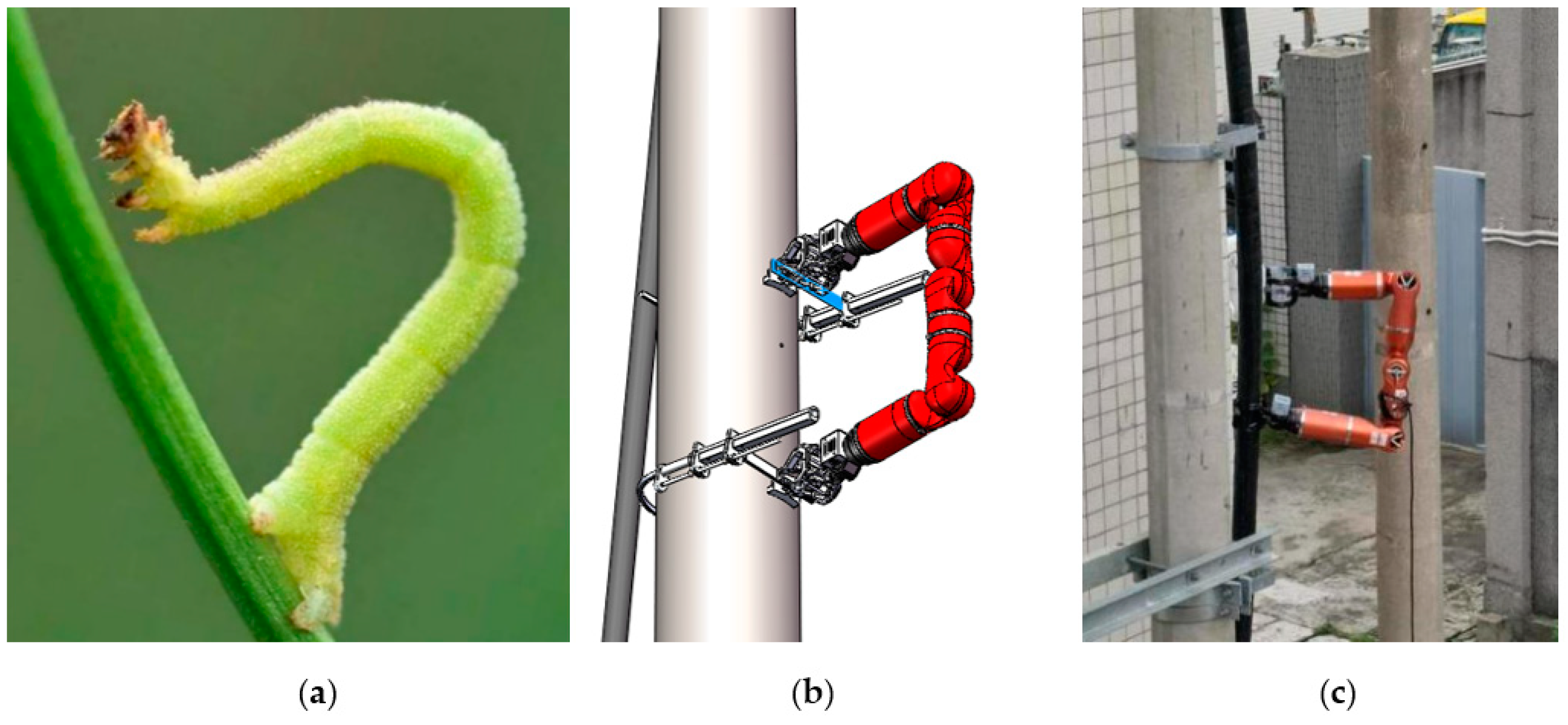
Figure 3.
Typical module types. (a) 1-type, (b) 7-type, (c) 6-type (the gripper).
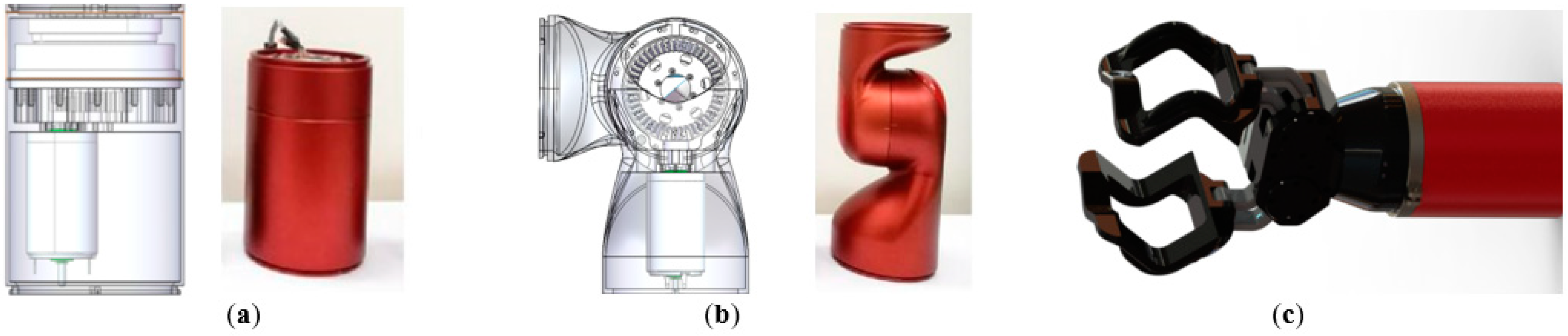
Figure 4.
Different configurations robots made up of different modules. (a) 6-1⊥7//7//7⊥1-6, (b) 6-7//1⊥7⊥1//7-6, (c) 6-7//7//7-6, (d) 6-1⊥7//1//7⊥1-6.
Figure 4.
Different configurations robots made up of different modules. (a) 6-1⊥7//7//7⊥1-6, (b) 6-7//1⊥7⊥1//7-6, (c) 6-7//7//7-6, (d) 6-1⊥7//1//7⊥1-6.


Figure 5.
The biomimetic power distribution live working robot system. (a) Hardware system of the robot, (b) control interface of the robot.
Figure 5.
The biomimetic power distribution live working robot system. (a) Hardware system of the robot, (b) control interface of the robot.
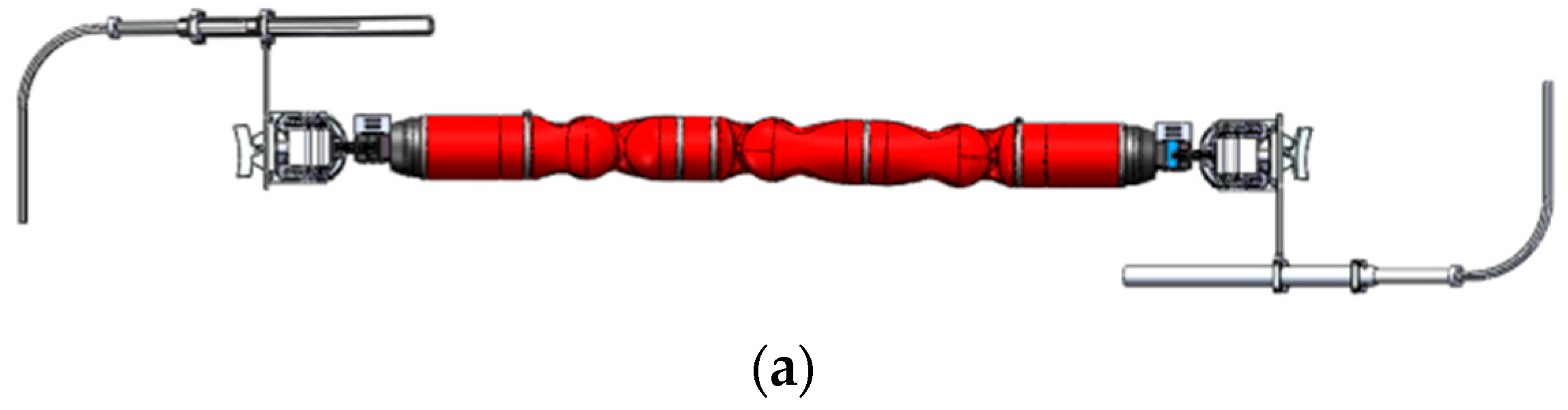

Figure 6.
Pole-climber.
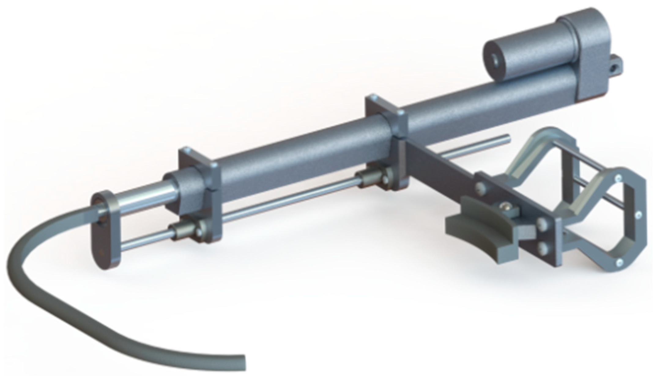
Figure 7.
Profile modeling for the small gripper. (a) Profile model, (b) actual picture.

Figure 8.
Electrical system design of robot.

Figure 9.
System architecture.

Figure 10.
Inchworm gait. (a) Initial state, (b) motion 1, (c) motion 2, (d) completed state, (e) front elevation of initial motion, (f) front elevation of motion 1, (g) front elevation of motion 2, (h) front elevation of completed state.
Figure 10.
Inchworm gait. (a) Initial state, (b) motion 1, (c) motion 2, (d) completed state, (e) front elevation of initial motion, (f) front elevation of motion 1, (g) front elevation of motion 2, (h) front elevation of completed state.
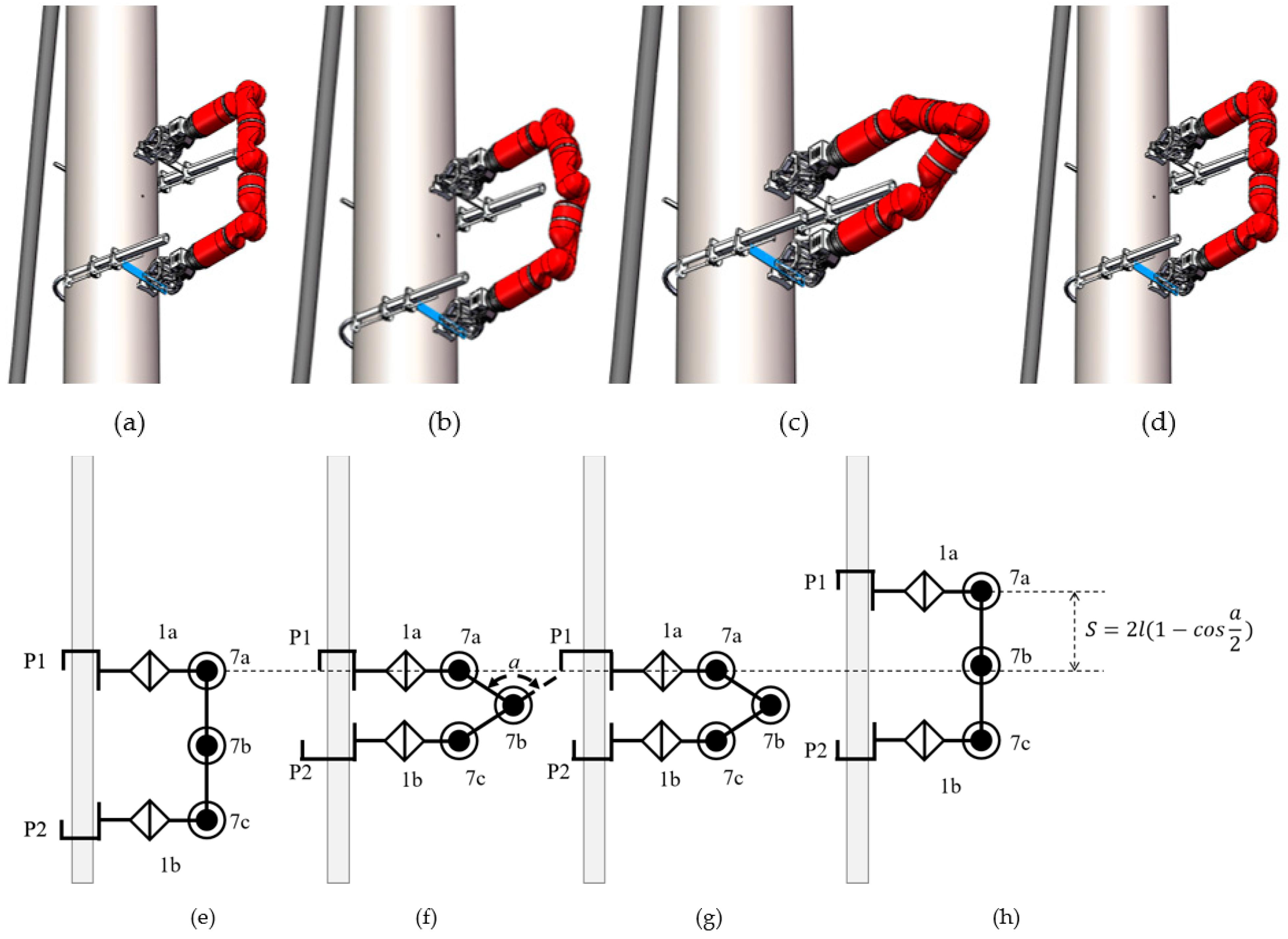
Figure 11.
Motor torque waveforms of inchworm gait.

Figure 12.
Turning-around gait. (a) Initial state, (b) motion 1, (c) motion 2, (d) completed state, (e) side elevation of initial motion, (f) side elevation of motion 1, (g) side elevation of motion 2, (h) side elevation of completed state.
Figure 12.
Turning-around gait. (a) Initial state, (b) motion 1, (c) motion 2, (d) completed state, (e) side elevation of initial motion, (f) side elevation of motion 1, (g) side elevation of motion 2, (h) side elevation of completed state.

Figure 13.
Motor torque waveforms of turning-around gait.
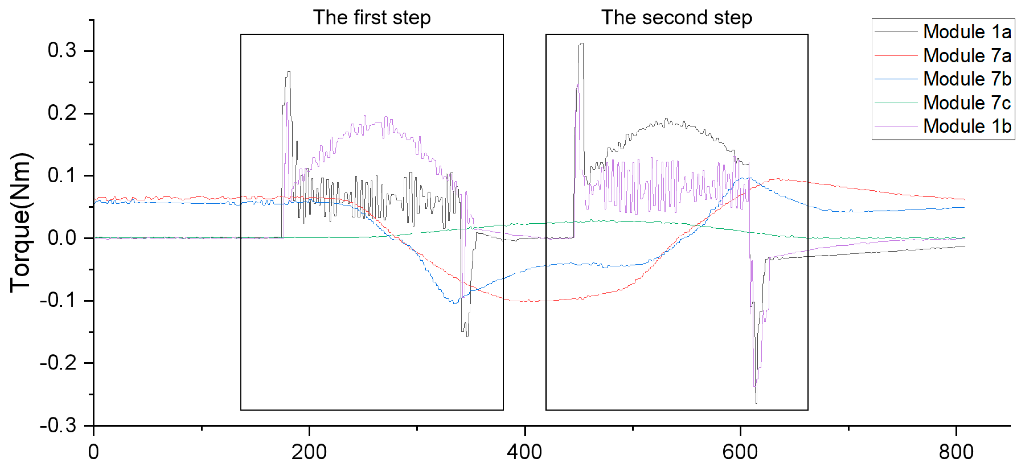
Figure 14.
Turning-over gait. (a) Initial state, (b) motion 1, (c) motion 2, (d) completed state, (e) front elevation of initial motion, (f) front elevation of motion 1, (g) front elevation of motion 2, (h) front elevation of completed state.
Figure 14.
Turning-over gait. (a) Initial state, (b) motion 1, (c) motion 2, (d) completed state, (e) front elevation of initial motion, (f) front elevation of motion 1, (g) front elevation of motion 2, (h) front elevation of completed state.
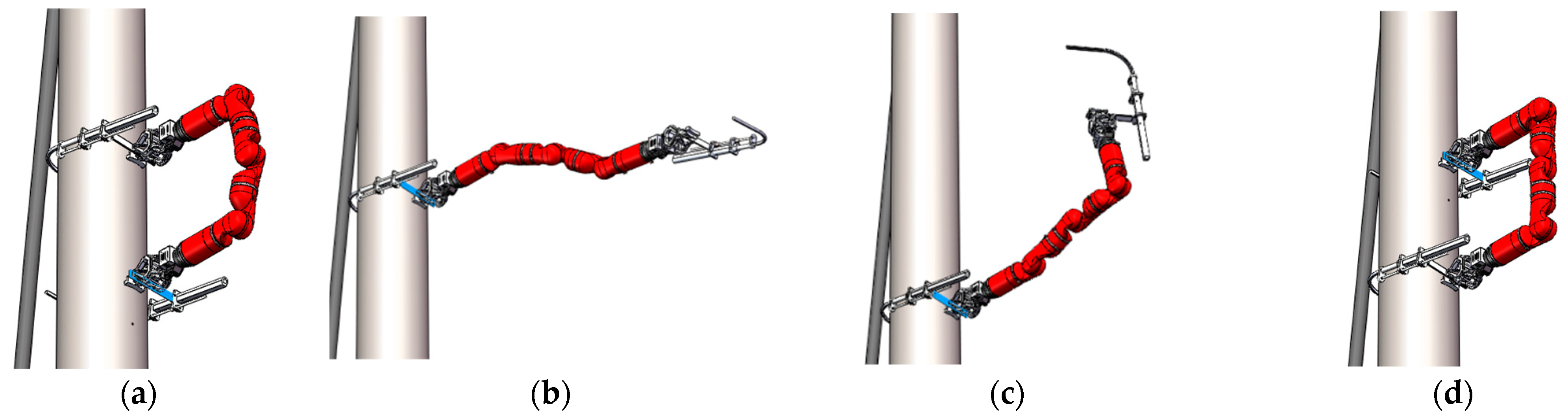

Figure 15.
Motor torque waveforms of turning-over gait.
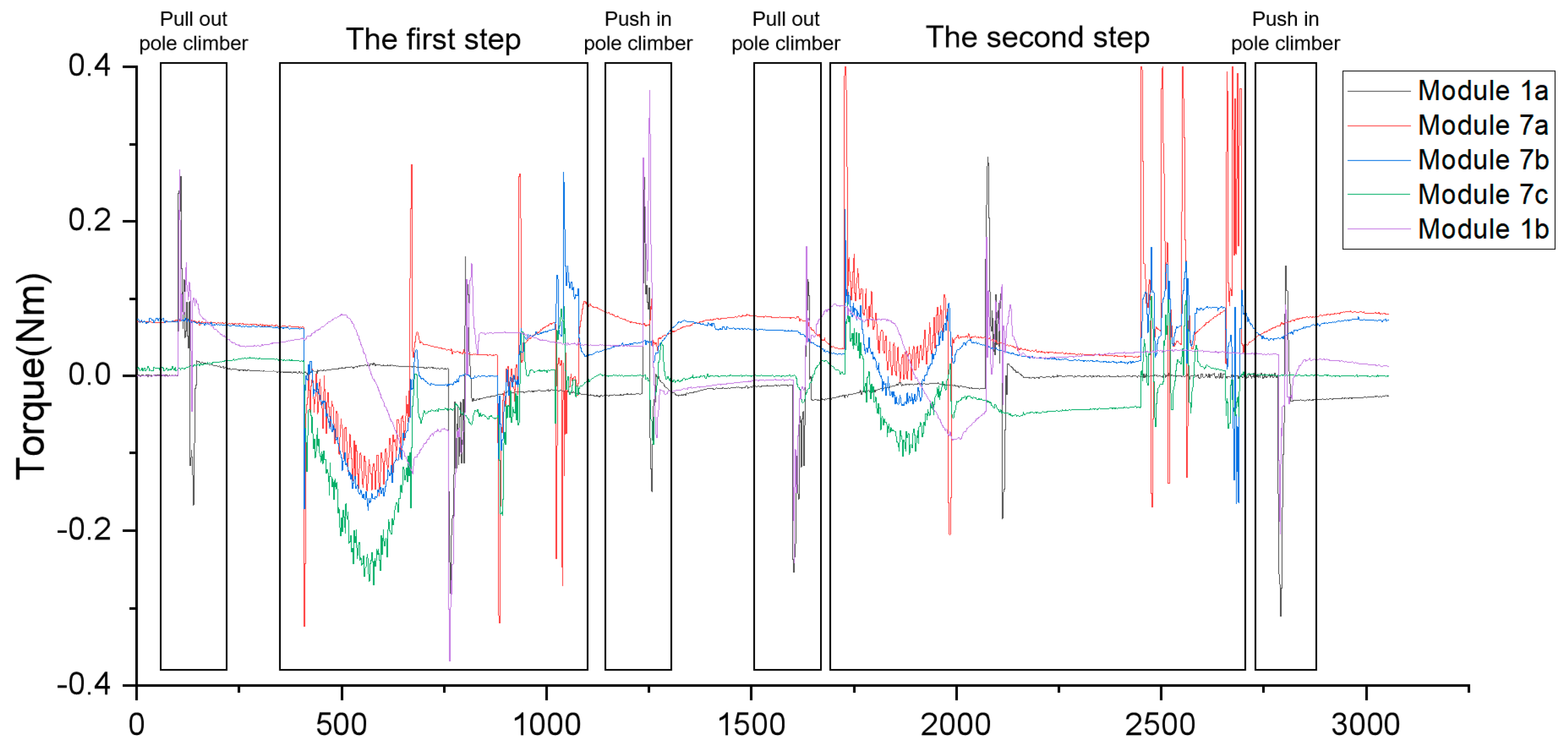
Figure 16.
Ability analysis of overcoming obstacles.

Figure 17.
Stress analysis of gripper. (a) The contact position of the clamping stage, (b) the contact position of during loading. Adapted from [6].
Figure 17.
Stress analysis of gripper. (a) The contact position of the clamping stage, (b) the contact position of during loading. Adapted from [6].
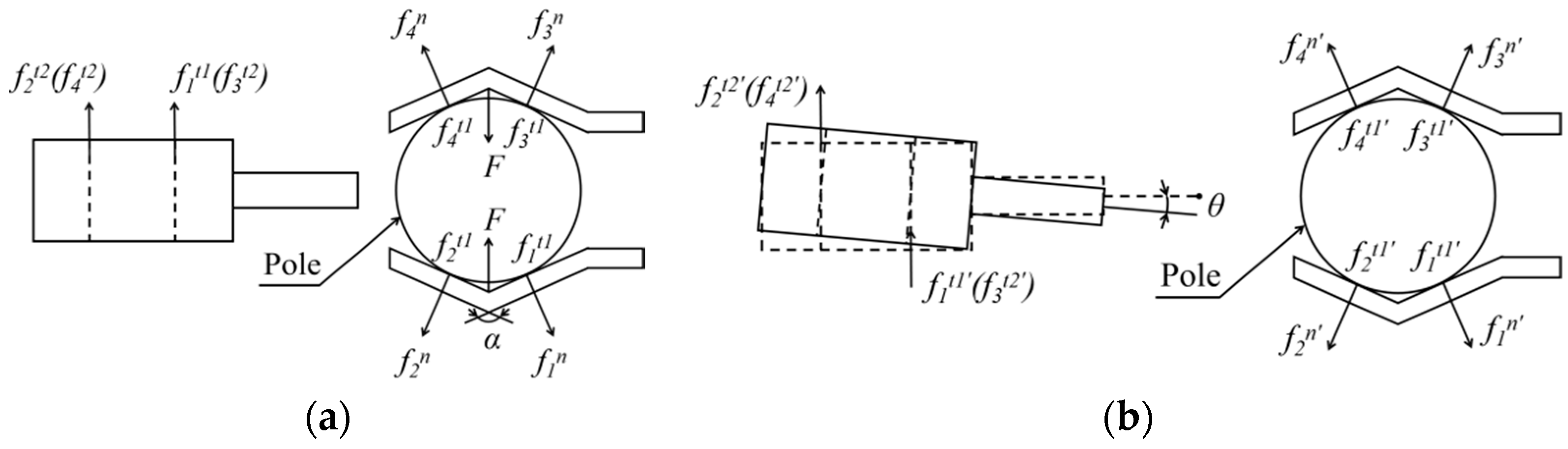
Figure 18.
Force analysis of profile model.
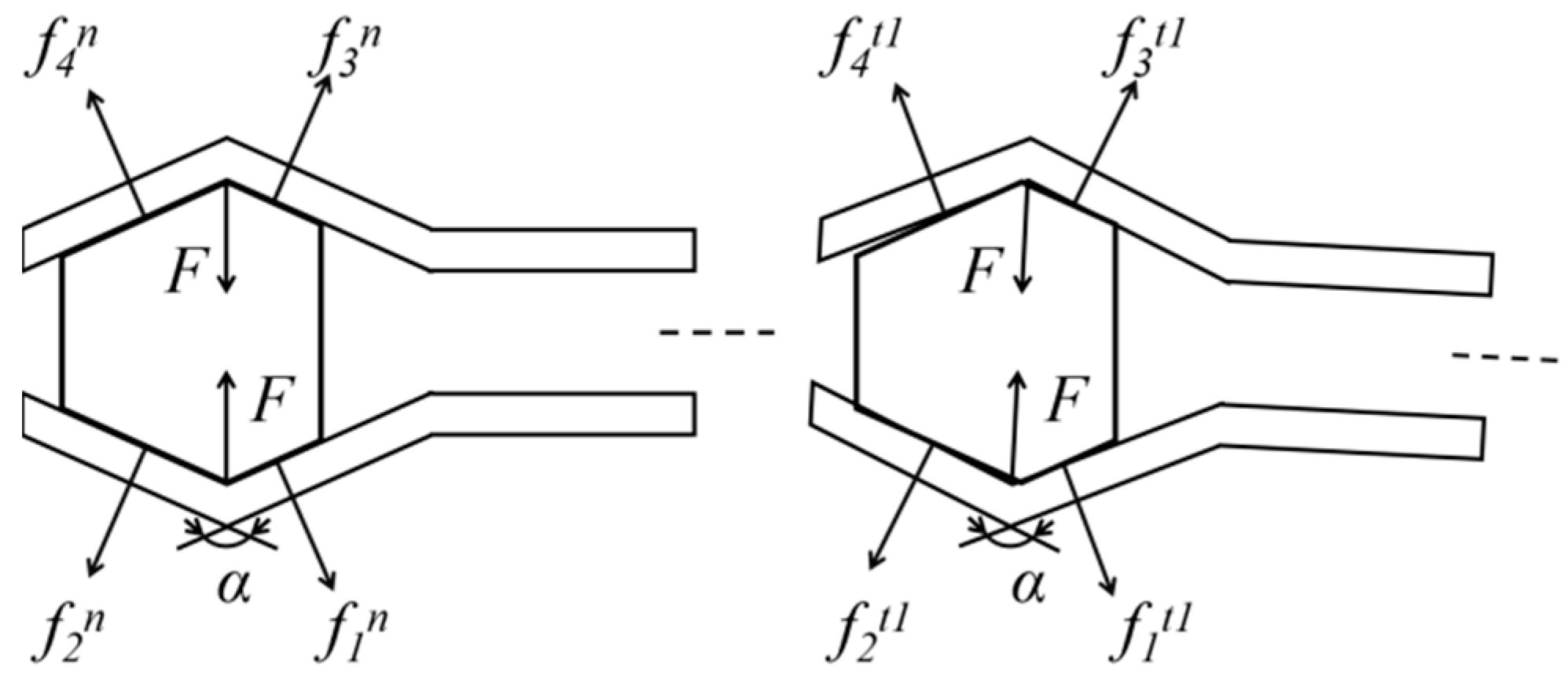
Figure 19.
Self-locking of pole climber.
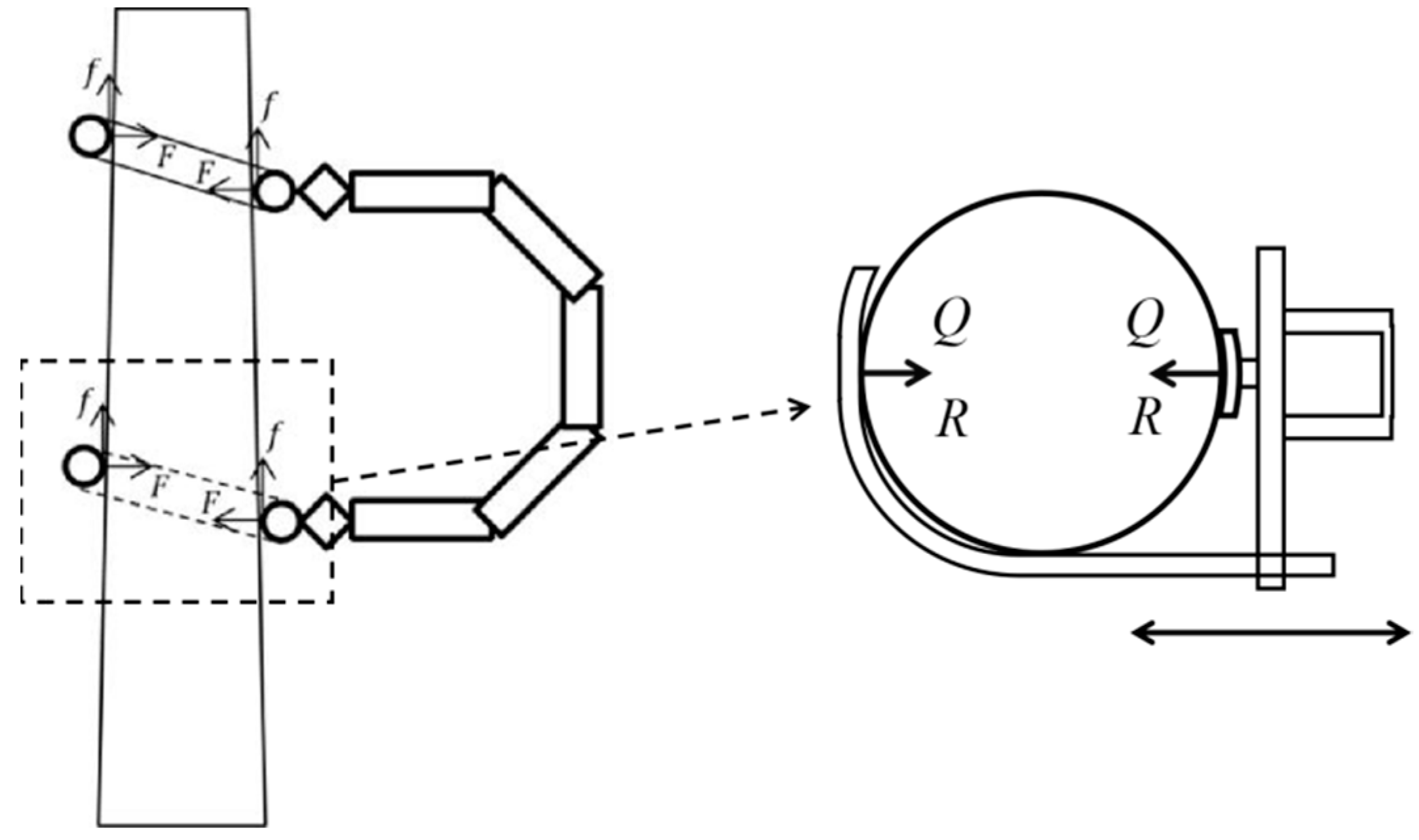
Figure 20.
Operation process. (a) Initial state, (b) motion 1, (c) motion 2, (d) motion 3, (e) front elevation of operation process.
Figure 20.
Operation process. (a) Initial state, (b) motion 1, (c) motion 2, (d) motion 3, (e) front elevation of operation process.

Figure 21.
Operation position. (a) Horizontal arrangement, (b)vertically arrangement, (c)multi-circuit line on the same pole.
Figure 21.
Operation position. (a) Horizontal arrangement, (b)vertically arrangement, (c)multi-circuit line on the same pole.
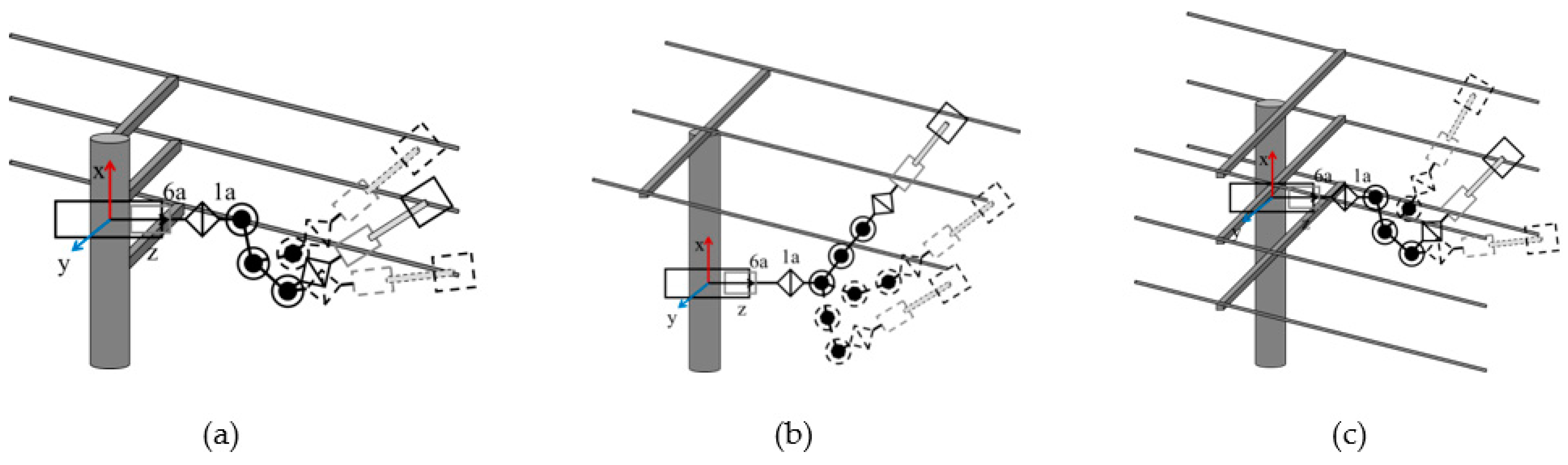
Figure 22.
Operation motion. (a) aiming, (b) grasping, (c) touching, (d) releasing.

Figure 23.
Double robots cooperate to replace the arrester.

Figure 24.
Robot structure force simulation. (a) 1-type modular motor base, (b) 1-type modular reducer base, (c) 7-type modular base, (d) extend base.
Figure 24.
Robot structure force simulation. (a) 1-type modular motor base, (b) 1-type modular reducer base, (c) 7-type modular base, (d) extend base.

Figure 25.
Force analysis of grasping claw.
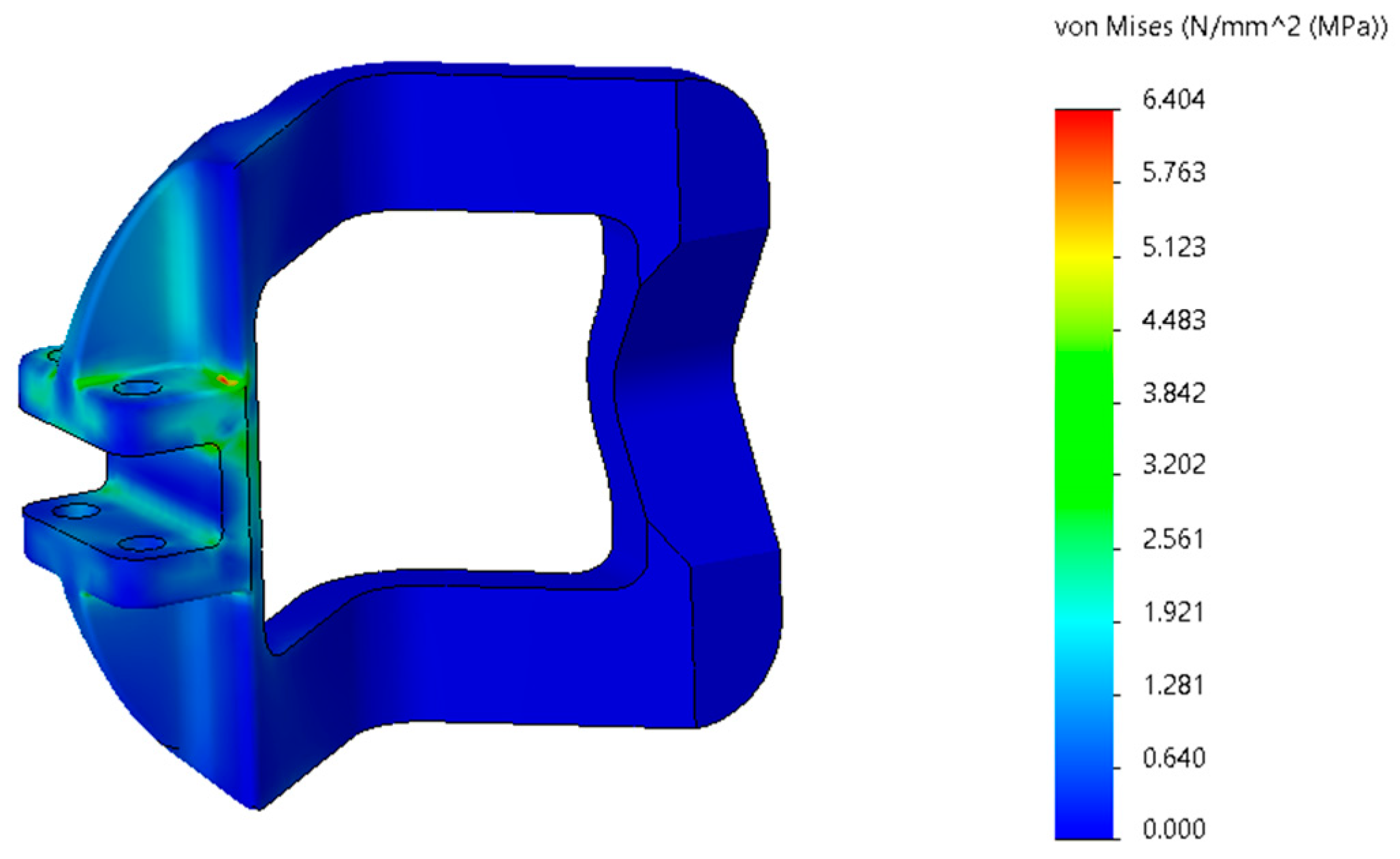
Figure 26.
Test of grasping force.
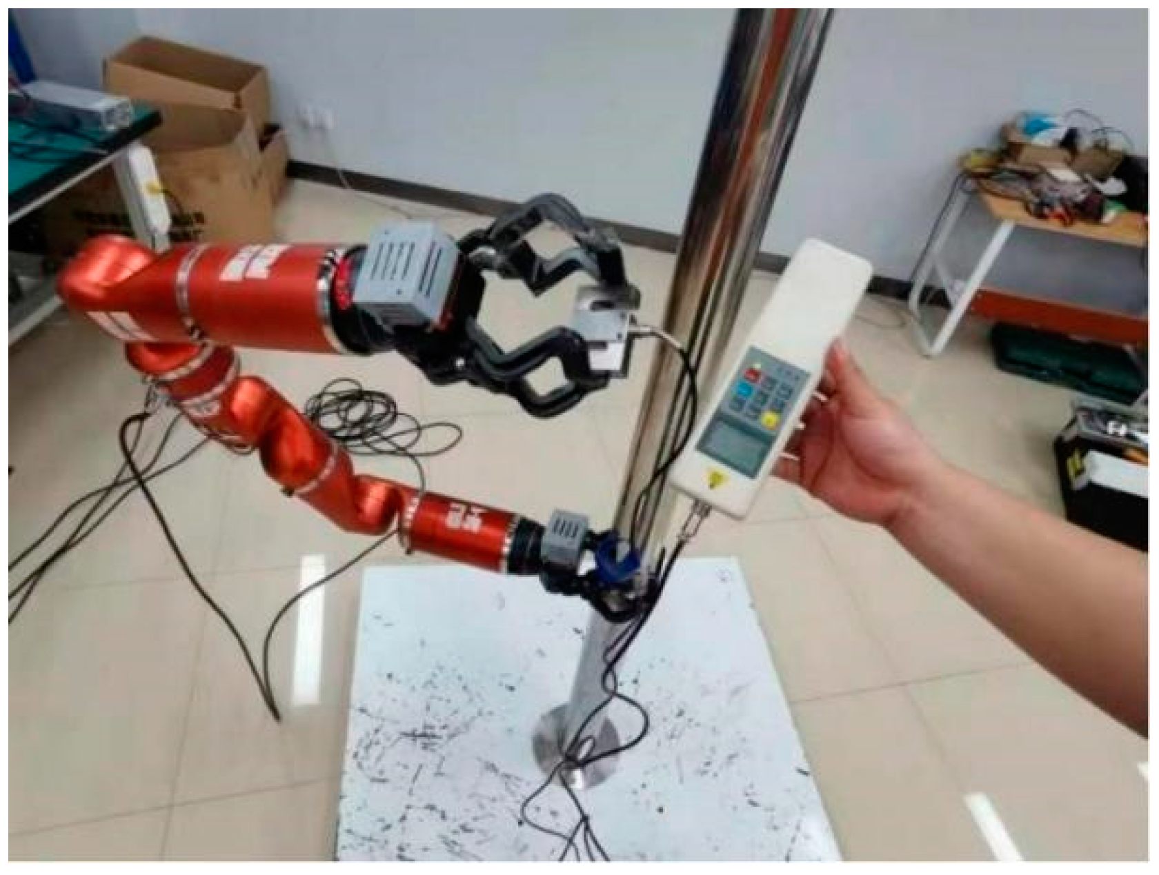
Figure 27.
Test of range motion. (a) Test scenario, (b) equivalent manipulator, (c) motion range of manipulator.
Figure 27.
Test of range motion. (a) Test scenario, (b) equivalent manipulator, (c) motion range of manipulator.
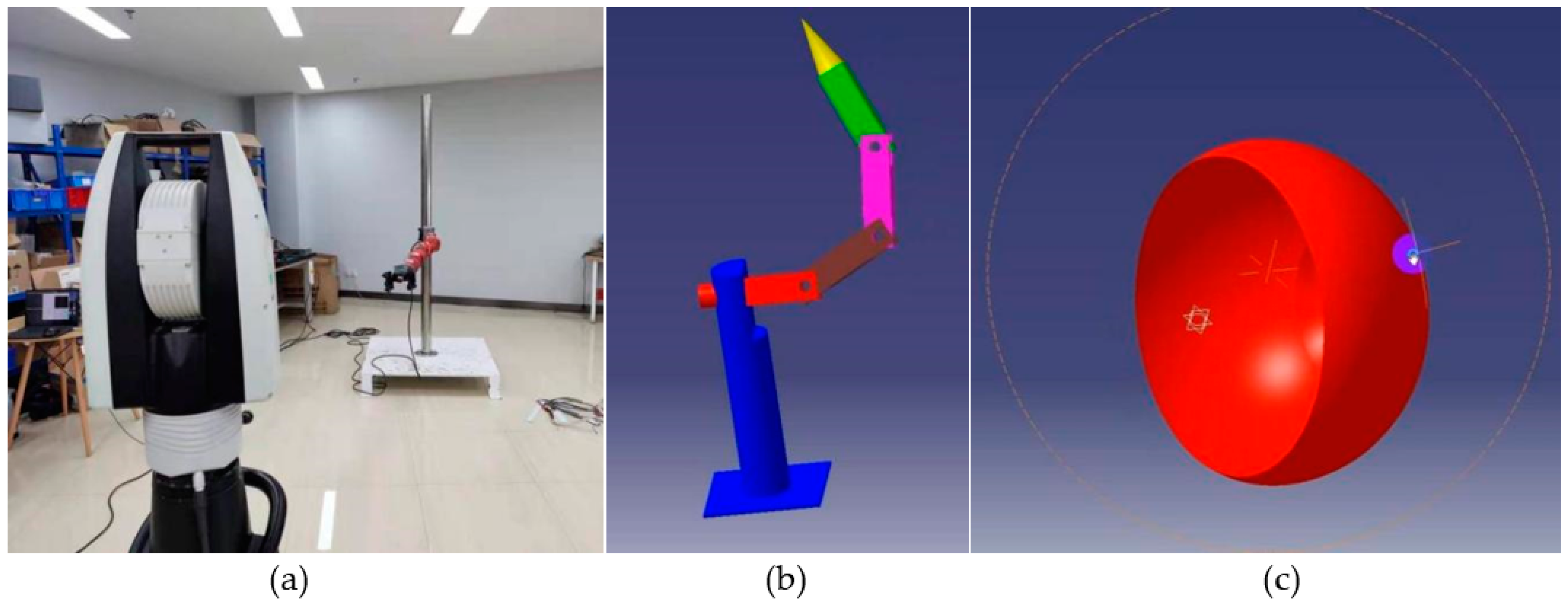
Figure 28.
The robot climbing speed tests.
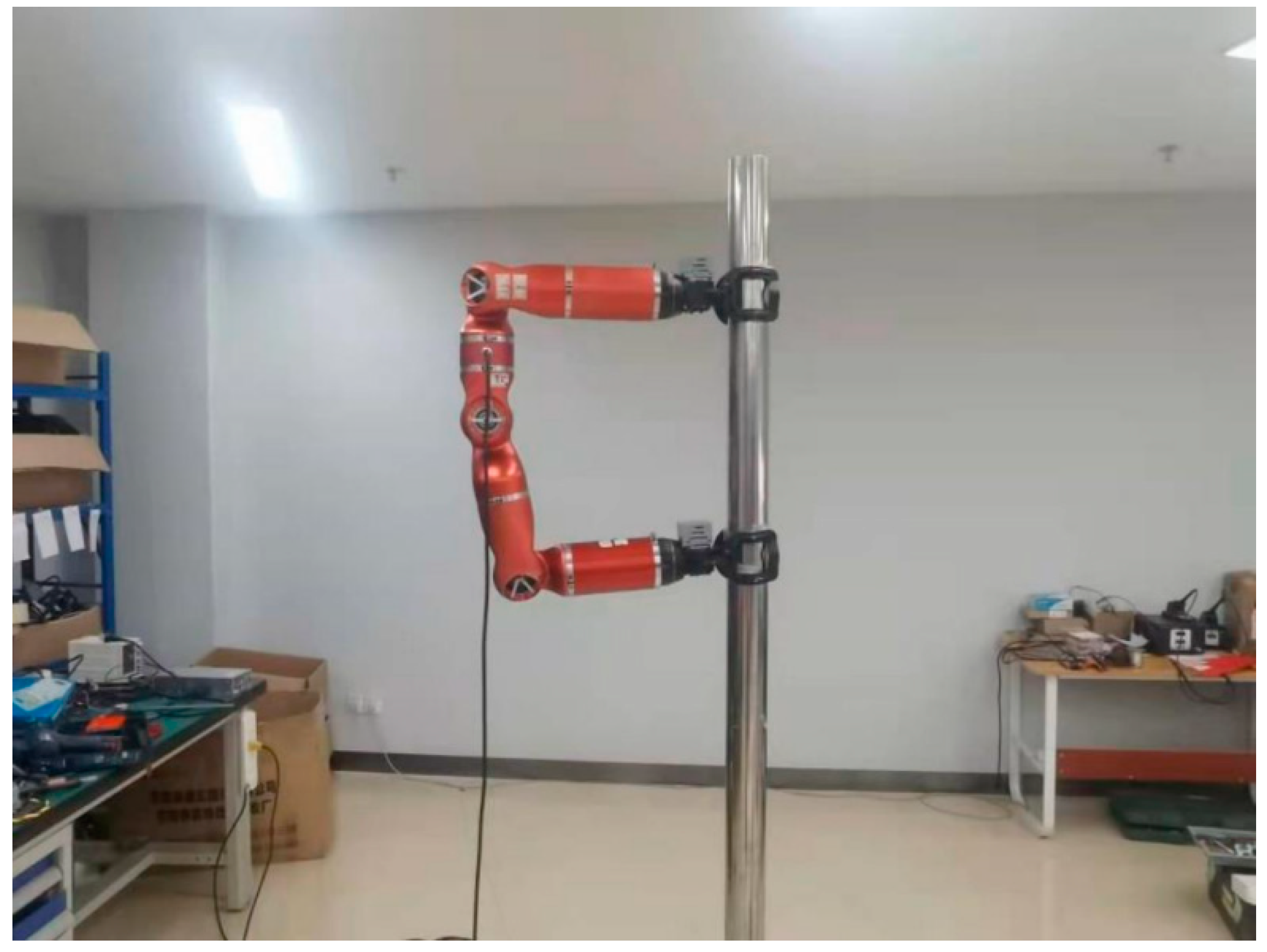
Figure 29.
The robot climbs the pole for testing. (a) Concrete pole climbing, (b) power cable passage climbing.
Figure 29.
The robot climbs the pole for testing. (a) Concrete pole climbing, (b) power cable passage climbing.
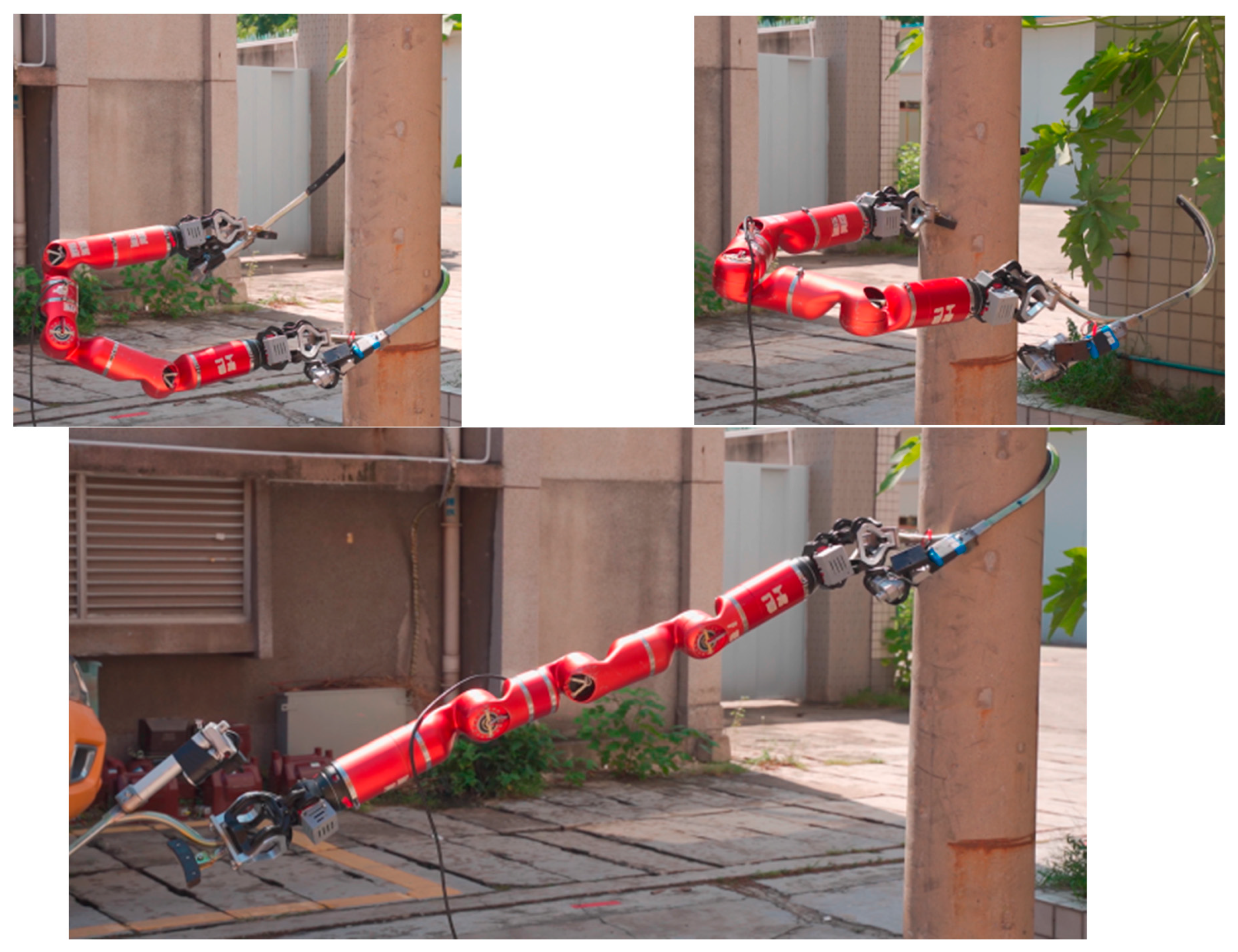
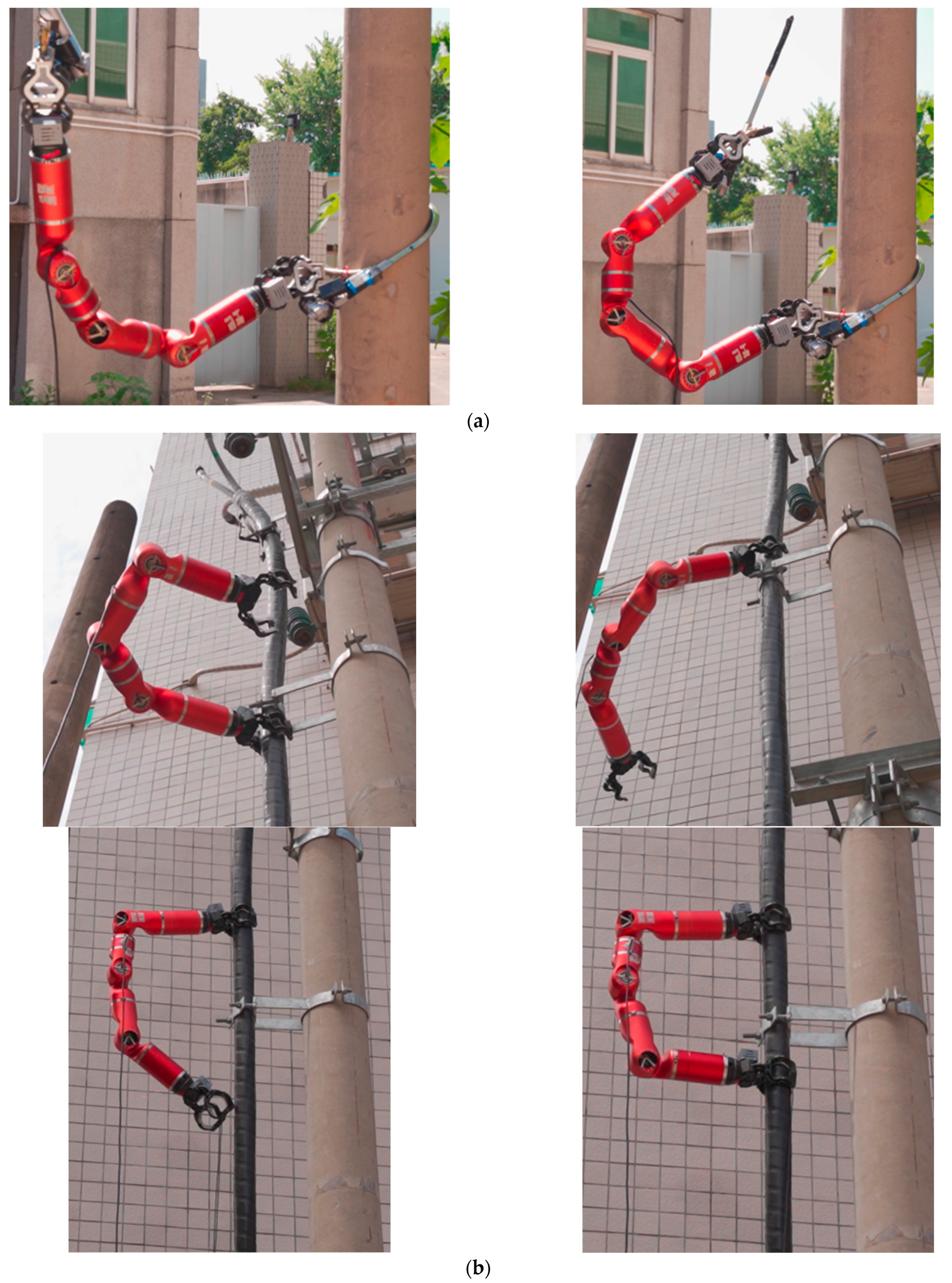
Figure 30.
Simulation of several live working projects. (a) Verification of live part, (b) grounding, (c) installing fault indicator.
Figure 30.
Simulation of several live working projects. (a) Verification of live part, (b) grounding, (c) installing fault indicator.

Table 1.
Features of the three climbing gaits.
| Climbing Gaits | Inchworm | Turning-Around | Turning-Over |
|---|---|---|---|
| Key module | 7-type | 1-type | 7-type |
| Max step length | 2l1 | 2l1 | |
| Space required | Small, 2D | Middle, 3D | Big, 2D |
| Obstacle climbing ability | Least | Good | Good |
| Biomimetic | Yes, inchworm | Yes, human legs | No |
Table 2.
Test value of grasping force.
| Test Results | |
|---|---|
| Grasping force | 0.6358 kN = 635.8 N |
| 0.6072 kN = 607.2 N | |
| 0.6062 kN = 606.2 N | |
Table 3.
Test value of motion range.
| Test Items | Model | Test Results |
|---|---|---|
| Robot 6 DoF attitude performance detection and calibration | Leica-AT960LR | Maximum radius: 1635.00 mm |
| Minimum radius: 1108.10 mm |
Table 4.
Position repeatability.
| Position | Test Results | |
|---|---|---|
| Position Repeatability RP1 | P1 | 2.011 mm |
| P2 | 1.694 mm | |
| P3 | 2.230 mm | |
| P4 | 2.012 mm |
Table 5.
Test of climbing speed.
| Climbing Distance (m) | Time (s) | Climbing Speed (m/s) |
|---|---|---|
| 2 m | 28.57 | 0.07 |
| 2 m | 26.64 | 0.08 |
| 2 m | 29.43 | 0.07 |
Publisher’s Note: MDPI stays neutral with regard to jurisdictional claims in published maps and institutional affiliations. |
© 2022 by the authors. Licensee MDPI, Basel, Switzerland. This article is an open access article distributed under the terms and conditions of the Creative Commons Attribution (CC BY) license (https://creativecommons.org/licenses/by/4.0/).
Share and Cite
MDPI and ACS Style
Luo, J.; Guo, P.; Lin, Y. A Novel Modular Biomimetic Live Working Robot for Power Distribution Line. Machines 2022, 10, 195. https://doi.org/10.3390/machines10030195
AMA Style
Luo J, Guo P, Lin Y. A Novel Modular Biomimetic Live Working Robot for Power Distribution Line. Machines. 2022; 10(3):195. https://doi.org/10.3390/machines10030195
Chicago/Turabian StyleLuo, Jianbin, Peng Guo, and Yueke Lin. 2022. "A Novel Modular Biomimetic Live Working Robot for Power Distribution Line" Machines 10, no. 3: 195. https://doi.org/10.3390/machines10030195
Note that from the first issue of 2016, this journal uses article numbers instead of page numbers. See further details here.