Review

A Comprehensive Survey on Fault Tolerance in Multiphase AC Drives, Part 2: Phase and Switch Open-Circuit Faults

by
Alejandro G. Yepes
1,*,
Ignacio Gonzalez-Prieto
2,
Oscar Lopez
1,
Mario J. Duran
2 and
Jesus Doval-Gandoy
1
1
Applied Power Electronics Technology Research Group (APET), CINTECX, Universidade de Vigo, 36310 Vigo, Spain
2
Department of Electrical Engineering, Engineering School, University of Malaga, 29071 Malaga, Spain
*
Author to whom correspondence should be addressed.
Machines 2022, 10(3), 221; https://doi.org/10.3390/machines10030221
Submission received: 31 January 2022 / Revised: 11 March 2022 / Accepted: 15 March 2022 / Published: 21 March 2022
(This article belongs to the Special Issue Feature Papers to Celebrate the First Impact Factor of Machines)

Abstract

:
Multiphase machines are very convenient for applications that require high reliability. In this two-part survey, the state of the art about fault tolerance in multiphase drives is reviewed. In Part 1, an overview including numerous fault types was presented, along with fundamental notions about multiphase drives. Here, in Part 2, the focus is placed on phase/switch open-circuit (OC) faults in particular, which have received the most attention in the literature. Phase OC failures involve OCs in stator phases or in converter-machine connections, and switch/diode OCs are frequently dealt with similarly or identically. Thanks to the phase redundancy of multiphase drives, their operation can be satisfactorily continued under a certain number of OCs. Nonetheless, the procedure to follow for this purpose is far from unique. For given OC fault conditions, numerous fault-tolerant possibilities can be found in the literature, each of them with different advantages and disadvantages. Moreover, a great variety of methods have also been devised to detect and diagnose phase/switch OC failures so that, as soon as possible, the most appropriate fault-tolerance measures are applied. Thus, given the broad literature about tolerance to phase/switch OC faults in multiphase drives, the survey presented here is expected to be of great interest for the research community and industry.

1. Introduction

Multiphase (n-phase) machines are very attractive for applications where high reliability is sought, such as electric vehicles of various kinds (including aerospace ones) [1,2,3,4,5] and standalone/off-shore generation [6]. Not surprisingly, the literature about fault tolerance in multiphase drives has not ceased to increase, especially during the last years.
In Part 1 of this two-part survey, the fundamentals about the categories of multiphase machines and converters were given, a general overview about the potential faults and about the preferred topologies in multiphase drives was presented, and the publications concerning most fault types (except phase/switch OCs) were surveyed in detail. Nevertheless, since phase/switch OCs are by far the most commonly addressed failures in the literature, more space is devoted specifically to them here, in Part 2.
The general classification of faults in ac drives from Part 1 is reproduced in Figure 1 for the sake of convenience. As illustrated in this figure, OC faults can arise in different parts of an ac drive, because of numerous possible reasons. For instance, the connections (lines) between stator terminals and converter legs may suffer OC as a consequence of the same causes that give rise to high-resistance connections (see Part 1), that is, damage or contamination of the contact surfaces, vibration, thermal cycling, and poor workmanship [7]. An OC failure may occur instead in a machine stator phase winding, due to similar origins as stator short-circuit (SC) faults, that is, mechanical, electrical, thermal, or environmental stress [8]. Either of these situations (line or stator OC) result in practice in a phase OC, that is, current flow is completely prevented through the phase affected by the OC. (In machines with stator phase connections different from star, such as hexagon connection for n = 6 , an OC in a line does not imply OC (zero current) in a stator phase. Nevertheless, in general the term “phase OC” is also used through the paper to refer to line OCs for the sake of simplicity and generality. Note that star connection is by far the most common one. When it is desired to refer to the specific case of line OC excluding stator phase OCs, the term “line OC” is employed.)
In addition, as explained in Part 1, a phase OC can result from completely opening such a phase (e.g., using fuses or bidirectional switches) as a remedy to many other kinds of faults, such as switch OC/SC faults, high-resistance connections, current-sensor faults, or isolation of converter module (in modular drive) because of failures in its dc link, control unit, power supply, and so on. These conversions from other faults into phase OCs are illustrated by brown dashed lines in Figure 1. Furthermore, switch OC or switch-gating failures such that the respective free-wheeling diodes still conduct can be treated as phase OCs assuming that the diode conduction behaves as a disturbance rejected by closed-loop current control, even if the faulty converter leg is not isolated (provided other switch(es) of such leg(s) are turned off) [9].
The publications addressing all these scenarios of phase OCs (or equivalent) are surveyed here, in Part 2. The causes (already discussed), detection methods, and tolerance approaches of phase OC faults are summarized in Figure 2.
There are nonetheless many cases where faults are not handled as phase OCs. Most of them are not OC failures, and they have already been addressed in Part 1. There are also some publications where OC faults in switches are not treated as phase OCs either; they are reviewed here in Part 2 as well. Open-switch faults can be due to multiple different reasons, including overcurrent, electrical/thermal stress, failures in gating signals, and so on [10,11]. The detection and tolerance techniques for these faults are also in agreement with the classification displayed in Figure 2. In any case, it should be emphasized that, due to the aforesaid reasons, only some of the publications about fault detection in multiphase drives distinguish between switch and phase OC faults, and practically none of those about fault tolerance do (with just a few exceptions [9,12,13,14,15,16,17]).
As shown in Figure 2, the diagnosis methods of phase/switch OC faults may be divided into model-based (MB), knowledge-based (KB), or signal-based (SB) ones [18]. Concerning tolerance to OC failures, specific control methods have been developed for this purpose in the literature, because conventional ones are not suitable for operation under these faults. These particular control strategies can be enabled after fault detection and reconfiguration (traditional approach) [6], or they can be already operating in healthy conditions and provide natural fault tolerance without reconfiguration (recent trend) [19]. On the other hand, with regard to the drive topology, the redundancy offered by the number of phases permits a satisfactory postfault performance without resorting to special topologies. Nevertheless, it is sometimes convenient to install certain drive topologies (converter, stator phase/neutral connections, etc.) that provide better postfault performance (e.g., in terms of achievable output power) [20,21,22], or to reconfigure the drive in this manner once the fault arises [23,24,25]. The literature is broadly classified in this regard in Table 1. There are also a few papers about tolerance to phase/switch OC faults that do not fit in this general classification, including some focused on machine design [26,27,28,29,30,31,32,33,34,35,36,37,38] or on machine modeling [39,40,41,42]. Note that many of these publications were also discussed in Part 1 concerning other types of faults.
The remainder of Part 2 is organized as follows (note that the table of contents of the paper is included in the pdf file as bookmarks). The existing detection methods of phase/switch OC faults are reviewed in Section 2. The control techniques for OC-fault tolerance are addressed in Section 3. The drive topologies for improving the tolerance to OC failures are discussed in Section 4. The conclusions of Part 2 are summarized in Section 5. Abbreviations are listed at the end.

2. Detection of Phase/Switch OC Faults

As previously mentioned, phase/switch OC faults can be regarded as one of the most usual electrical failures in ac drives [2], and for this reason a significant number of works are focused on the diagnosis of this undesired incident [15,18,43,44,45,46,47,48,49,50,51,52,53,54,55,56,57,58,59,60,61,62,63,64,65,66,67,68,69,70,71,72,73,74,75]. The detection of OC faults and the identification of the affected phases have typically been mandatory tasks in order to ensure a proper postfault reconfiguration [6]. An exceptional scenario exists when the fault tolerance is achieved without fault diagnosis and postfault reconfiguration, but this case is discussed independently later, in Section 3.6. Furthermore, if the OC situation emerges as a consequence of the detection and tolerant procedure of other faults (see Figure 1), as discussed in Part 1, then the diagnosis of the OC is not necessary either. Nonetheless, tolerance to OCs based on OC-fault diagnosis and adequate reconfiguration is still common in current multiphase drives, as shown by the fact that most of these detection methods were proposed during the last five years [15,18,44,45,46,47,50,51,52,54,55,56,57,58,59,60,61,62,71,72,73,74,75].
As for other kinds of failures, strictly speaking, the diagnosis may consist of fault detection, fault-type identification, and location (e.g., faulty phase/switch) [287]. Notwithstanding, in many of the diagnosis methods available in the literature of multiphase drives, the three goals are achieved simultaneously.
In order to offer OC-fault identification, in general, the following three main approaches can be found in the literature [18]:
  • Model-based (MB) methods: an observer using a system model is employed to identify the faults, for example, when the measured signals deviate from the ones predicted for a healthy drive. No extra hardware is required, but to obtain adequate performance, a high accuracy is necessary in the model, which is particularly difficult when the electrical parameters change with operating conditions.
  • Knowledge-based (KB) methods: the fault diagnosis is attained using advanced algorithms such as neural networks, deep-learning technologies, or similar strategies, based on historic values (knowledge) from the system. Although this alternative does not require an accurate model, the computational burden is often excessive for real-time implementation.
  • Signal-based (SB) methods: the symptoms that some signals exhibit under failures are exploited to diagnose the fault. For this purpose, voltage or current signals may be monitored. If the current signals are employed, the fault is identified using only sensors that commonly exist for closed-loop control. The special behavior of the monitored signals in case of faults may be indirectly excited by the active injection of certain suitable signals, which some authors define as an additional category of diagnosis techniques [288].
This general classification is also suitable for diagnosis of faults other than OCs, such as those surveyed in Part 1. In any case, concerning multiphase drives, phase/switch OC failures are the only ones for which several detection methods can be found for each of these three classes. Nearly all the diagnosis techniques reviewed in Part 1 were SB. The main characteristics of the existing detection approaches for phase/switch OC faults in multiphase drives are summarized in Table 2. From this table, it can be observed that some MB [43,44,45,46,63,64,65] and KB [45,46,47,66] solutions for OC identification are available, even though SB ones [15,18,44,48,49,50,51,52,53,54,55,56,57,58,59,60,61,62,65,67,68,69,70,71,72,73,74,75] are the most popular by far.
Before analyzing the works displayed in Table 2, it is necessary to acknowledge the desirable features of an ideal online fault-detection strategy. In this regard, the following five requirements were postulated in [54], in the context of OC faults.
(R1)
Use of non-invasive techniques and lack of extra hardware (e.g., voltage sensors).
(R2)
Obtain short detection times (less than a fundamental period), so that the effects of torque ripple, vibrations, and large currents are reduced.
(R3)
Avoid complexity and high implementation effort.
(R4)
Independence from operating conditions (e.g., load value, transients, etc.).
(R5)
Independence from control strategy and/or machine parameters (without adding parameter observers).
With these requirements in mind, the evolution of multiphase phase/switch-OC detection methods can be reviewed in detail next, following the order from Table 2 and according to the aforementioned three classes: MB (Section 2.1), KB (Section 2.2), and SB (Section 2.3) techniques.

2.1. MB Detection Methods

In a paper from 2014 [43], an MB approach is suggested by Salehifar et al. to localize open-switch faults in voltage source converters (VSCs) supplying five-phase permanent-magnet synchronous machines (PMSMs). This algorithm estimates the fundamental and third-order components of each phase current by employing a machine model. These estimates are compared with the measured phase currents so that the fault situation is detected when the corresponding error (residue) is large. The method can distinguish between faults in the upper or lower switches of a leg by means of the respective residue sign. It is insensitive to operating conditions thanks to the use of a dynamic threshold, but an accurate machine model is required (adaptive identification based on recursive least squares is adopted). Therefore, despite the acceptable abilities of this solution [43] to localize OC faults, the requirement R5 cannot be satisfied, as shown in Table 2.
The same authors present in [63] a new MB OC-fault detection strategy, where a sliding-mode observer is implemented to predict the phase currents. In order to localize the fault occurrence, the real and estimated phase currents are compared using a cross-correlation factor, instead of a simple subtraction (residue), which would be more prone to false alarms. This technique permits the identification of multiple open-switch and open-phase faults. Nevertheless, it is relatively complex, and the machine parameters should be estimated to suitably adapt the proposed current observer; thus, R3 and R5 are not fulfilled.
In [64], a simpler current observer is adopted, based on applying an integral term to each of the phase-current errors. In this case, the observer is employed to locate the failure, and the fault alarm is priorly triggered if the cost function of a current finite-control-set model predictive control (FCS-MPC) yields an error over a certain threshold. Switch/phase OCs and switch SCs are distinguished by whether the corresponding phase current is zero or not. However, regarding R5, this current observer also relies on the knowledge of the machine parameters. Moreover, this technique [64] is only suitable when using a particular type of FCS-MPC (further discussed in Section 3.4.2).
The scheme presented in [65] is a combination of an MB approach for the detection and an SB one for localization. For the former, two cost functions are calculated. Both are computed as the squared error between reference and predicted phase currents, with the latter being obtained from a machine model and the VSC voltage vector that yields the larger current error. One of these cost functions (also used for current FCS-MPC) is much more sensitive to the fault occurrence than the other one. Accordingly, the fault alarm is set when the difference between the pair of values from the two cost functions is large. Concerning the location process, it is performed by using a fault index for each phase, as a function of the reference and measured currents. Given that this method is designed for use in conjunction with FCS-MPC and not other types of control, R5 is not satisfied. Furthermore, regarding R2, the location of a phase OC may take about one fundamental cycle.
Another MB diagnosis strategy has recently been proposed by Gonçalves et al. in [44], for an asymmetrical six-phase PMSM. The errors between the predicted x-y currents of a model predictive control (MPC) and the measured currents are employed to localize open-phase faults and high-resistance connections. In addition, an alternative SB method is also developed for MPC, but in this case the fault indices are defined based on the x-y error in the tracking of the reference currents. The capability of both techniques to identify the aforementioned faults in the drive is confirmed by experimental results. Unfortunately, the detection time is omitted. Consequently, the requirement R2 (short detection time) is not guaranteed, as reflected in Table 2. It can also be noted that the SB variant is expected to be valid for other controllers (meeting R5), but not the MB one.

2.2. KB Detection Methods

Concerning KB methods for OC-fault detection [45,46,47,66], significant complexity and high implementation effort are commonly necessary. For this reason, the requirement R3 is not usually achieved when a KB strategy is selected for diagnosis (see Table 2). Additionally, the fault detection response can also be slower than for SB techniques, since a large amount of data is normally needed to identify the fault occurrence [47,66]. Different KB fault-detection methods have been implemented in five-phase drives.
For instance, in [45], Torabi et al. employ an adaptive self-recurrent wavelet neural network to identify faults symptoms by monitoring the gate drive signals from pulsewidth modulation (PWM) and the actual phase currents. The solution from this work is hybrid, because the applied KB approach is implemented in conjunction with a nonlinear model of the machine in order to predict the motor currents corresponding to healthy conditions. Regarding its performance, the fault is detected in less than one millisecond, despite implementing a KB approach. Fault location is provided using a fault classifier.
Next, in [46], the same authors apply a modification of this concept to a three-level diode neutral-point-clamped (NPC) inverter, in which the faulty switch is localized by a semi-supervised fuzzy clustering algorithm that integrates simulation and experimental data. Fault detection is more challenging with multilevel VSCs because the effect of switch failures on the output waveform is less significant, and a certain observed anomaly can be caused by different redundant switching states. In spite of these challenges, experimental results show that with this method a fault can be detected and localized in an interval shorter than one millisecond.
Olivieri [66] presents a technique to identify the occurrence of a phase OC fault in an encoderless five-phase PMSM. To this end, a feed-forward neural network is devised, where the α 1 - β 1 motor currents are used as inputs. With the proposed structure, only single open-phase faults can be diagnosed, and a greater number of neural networks would be needed to identify multiple phase faults.
Concerning the most recent KB solution [47], Yao et al. develop a fault-diagnosis method for five-phase marine current generators. On the one hand, empirical mode decomposition and Hilbert transform is applied for fault detection. On the other hand, variable-parameter particle swarm optimization is employed for fault-type identification and location, with the parameters being adapted by a support vector machine. The input signal is the projection of the α 1 - β 1 current onto the direct axis of the synchronous reference frame, that is, d 1 . The kind of fault is identified based on the pattern of this current. Addressing the robustness for different operating conditions (i.e., R5) is left for future work. As a significant advantage, this technique also diagnoses current-sensor faults.

2.3. SB Detection Methods

As shown in Table 2, SB fault-detection methods have been widely carried out using vector space decomposition (VSD) components [15,18,44,53,54,55,56,57,58,59,60,61,62,71,72,73,74,75], although monitoring just the phase currents has also been suggested for this purpose [48,49,50,51,52,67,68,69,70], especially in older papers. In a 2012 publication [48], Meinguet et al. propose the localization of open-phase faults by quantifying the imbalance of the phase currents, exploiting the fact that these signals are more affected by the occurrence of a fault than the main ( α 1 - β 1 ) VSD subspace. The fault is identified after several fundamental cycles. Alternatively, since an open-phase failure is characterized by null current in the damaged phase, a trivial solution to diagnose a phase OC is to check if the average during a certain period of any phase-current absolute [70] or squared [49,50,67,68,69] value is approximately zero. Unfortunately, this technique could also be relatively slow, because the detection takes at least as much time as the interval that is necessary for computing the average (e.g., a fundamental cycle). Moreover, false alarms can be triggered when the machine operates with small current magnitudes [48], especially near zero crossings if one attempts to set a short averaging time. Another method based on averaging current values was recently proposed by Mesai-Ahmed et al. [51] for asymmetrical six-phase IM drives. This technique calculates the average absolute values and the average values of the measured currents over a fundamental period, and provides a set of normalized numerical signatures to detect and localize the faulty devices. It is capable of identifying up to 54 different fault scenarios, involving multiple phase/switch OC faults, with no need for detection thresholds or tuning. However, R2 is not fulfilled either. Although phase currents can exhibit these limitations when monitored, Wen et al. recently proposed in [52] a fault-detection method based on them for identifying the sector affected by an OC fault, in a three-sector nine-phase PMSM. The alarm is set when the instantaneous (not average) absolute value of a phase current is lower than a threshold while the current error of said phase (with respect to its control reference) is large. Simulation and experimental results confirm its effectiveness for detecting single- or three-phase OC faults in one or two sectors. However, the current-measurement ripple, which depends on the drive and operating conditions, needs to be considered in the design to avoid false alarms (R4 and R5 are not met). Moreover, it is not suitable if it is desired to keep using the healthy phases of a sector with a single-phase OC, because the particular faulty phase within the sector is not found.
In spite of the low sensitivity of the main VSD subspace identified in [48], the analysis of the VSD components has been in fact the most popular option for the diagnosis of OC failures in multiphase systems. Many of these methods take advantage of the high sensitivity offered by the x-y subspaces (see Table 2).
Meinguet et al. [53] proposed a fault-detection method where the ratio between the negative and positive sequences of the α 1 - β 1 fundamental currents is employed to detect open-phase faults. The criterion to identify a phase OC is defined using a cumulative sum control chart algorithm. Unfortunately, the performance of the fault-detection index is affected by the machine speed and the controller gains, and as a consequence, the requirements R4 and R5 are not fulfilled. Moreover, other faults that cause α 1 - β 1 imbalance, such as eccentricity [289,290] or stator SCs [291,292], may lead to misdiagnosis. The secondary VSD subspaces, which could be useful for preventing this problem and finding clearer symptoms, are not exploited.
Taking advantage of the inherent secondary (x-y) subspaces of multiphase machines, Duran et al. [54] introduce an open-phase detection method for an asymmetrical six-phase induction machine (IM) driven by rotor field-oriented control (RFOC). The fault indices are derived considering the phase-OC condition (null current through the damaged phase) and the six-phase VSD transformation. Monitoring the x-y currents instead of the per-phase ones facilitates attaining fast and robust detection. This fault-detection method can be extended to different multiphase drives and control strategies, as illustrated in [71] for a five-phase IM driven by current FCS-MPC. Moreover, the developed fault indices allow the detection of open-switch faults as well [71]. In fact, these same fault locators may be employed to identify the specific OC switch, by just carrying out some additional non-complex analysis/operations [55,56]. For example, Kong et al. [55] reformulate the fault indices proposed in [71] and study the polarity of the secondary VSD components to obtain this extra information about the fault in a five-phase PMSM drive. Farag et al. [56] applied analogous fault-detection indices to a symmetrical six-phase IM, and additionally proposed the estimation of the average phase current after the fault detection to distinguish between phase/switch OCs and to achieve the location of the specific faulty switch. Consequently, although the fault detection time is short, its location takes more than one fundamental cycle. This technique [56] is able to diagnose broken rotor bars and high-resistance connections as well. It is also worth noting that the SB procedure proposed in [44] as an alternative to an MB one (see Section 2.1) also relies on the x-y currents and detects high-resistance connections, but the transient response has not been assessed so far.
Other publications present methods developed on the basis of the so-called symmetrical component theory [57,58], which is actually equivalent to distinguishing between the positive and negative sequences within the VSD subspaces [293]. In particular, in [57,58] the pattern of the symmetrical components of the stator current is employed to identify single and double OC faults in five-phase PMSMs. Arafat et al. [57] defined two fault indices as a function of the amplitude of the current symmetrical components. However, the measured currents need to be filtered to extract the fundamental component and its sequences, and no information about fault detection time is provided in the paper. In the case of Chen et al. [58], the diagnosis is performed based on the phase angle of the α 1 - β 1 current space vector (SV) over a fundamental period; namely, on the deviation from its expected value. This deviation is oscillating in the case of OC fault. Given that a fundamental cycle is required, R2 is not fulfilled, as indicated in Table 2.
However, many of these SB procedures assume that the current in the x-y plane(s) is nearly zero in healthy conditions. In contrast, some authors devised phase/switch-OC diagnosis SB methods that exploit the x-y current symptoms with robustness to harmonics (e.g., third) in the current references [60,62] or in the PMSM back-EMF [59,60,61,62]. These techniques satisfy the five requirements R1–R5, as shown in Table 2. Trabelsi et al. [59] proposed to calculate the centroid of the x-y current trajectory during a fundamental period, and locate a single-switch OC by means of its phase angle. Phase OCs are found by checking whether the mean absolute value of the phase current is zero during a certain interval, similarly to other aforementioned papers [49,50,67,68,69,70]. In spite of the averaging, the faults are detected in a brief time; this implies that the phase-current mean is computed over a short interval, which could aggravate the risk of false alarms at zero crossings when the current is low [48]. The signals are normalized by the two-norm of the VSD currents, to achieve independence from operating conditions. Later, the same authors presented another technique in [60], with greater robustness to the third harmonic in the back-EMF and in the current references (for increasing torque). New indices are derived for detecting single-switch OCs based on the VSD components of not only the measured currents, but also of their control references. Phase OCs are identified analogously to the preceding work [59]. To ensure R4, suitable normalization is applied, and the ratio between the first two back-EMF harmonics is considered for selecting the thresholds. More recently, Gonçalves et al. [61] implemented fault indices based on the mean value and the amplitude of the second current harmonic with respect to a rotor-oriented frame within the x-y plane. Integration of VSD variables is performed during half a fundamental cycle, avoiding the averaging of phase currents and the associated risks. Simulation results have demonstrated the ability of the method to detect open-phase faults in asymmetrical six-phase PMSMs. Although fifth and seventh back-EMF/deadtime harmonics are considered, null current references are assumed in the x-y plane. In this regard, the same authors improve this method in [62], where the non-zero current references are taken into account, and high-resistance connections are also diagnosed. Later, it is further enhanced in [44] so that the values of increased resistance are estimated, and smaller resistance imbalance can be detected.
The potential of the x-y signals of multiphase machines to be employed in OC-detection indices has also been confirmed in particular topologies such as series-connected six-phase PMSMs (two-motor drive) [75] or T-type three-level VSCs [15], and even under specific scenarios such as stator SCs [18]. In [75], Moraes et al. carry out the fault diagnosis for the two-PMSM drive in two stages. In the first one, the fault is detected using a single index, and in the second one, the fault is classified according to three fault indices. The method developed by Wang et al. in [15] allows the detection of switch OCs, phase OCs, and switch SCs in a T-Type three-phase VSC driving an asymmetrical six-phase PMSM. First, an SB approach using two fault indices is applied. For this purpose, different postfault features of the x-y currents are recognized. Then, an intervention-based diagnostic method (exciting the affected leg) is employed to additionally distinguish between the various kinds of faults. Since an invasive technique is necessary for this goal, the requirement R1 is not achieved. Finally, the strategy proposed by Guo et al. [18] for the identification of single open-switch failures has been specifically designed for the scenario of a symmetrical six-phase drive with two isolated neutral points under stator SC or OC. For this purpose, the four VSD currents are employed as inputs to a look-up table (LUT), in which the different fault situations are classified.
Wang et al. [72] have suggested a fault diagnosis approach considering five types of failures, including those in the speed sensor, dc-link voltage sensor, or current sensor (discussed in Part 1), as well as switch and stator OCs. MB strategies are designed to detect failures in the speed and dc-link voltage sensors, whereas the other faults are localized using an SB method. A three-step procedure has been designed to diagnose the problems related to current, that is, open-phase, open-switch, and current-sensor faults. In the first step, the amplitude of the x-y current SV is compared with a predefined threshold in order to detect abnormal behavior caused by any of these faults. In the second step, the mean values over a fundamental period of the current projection onto six axes within the x-y plane are computed, and the lowest one permits discarding all fault scenarios except four. These six axes correspond with the potential x-y current trajectories under these faults. Finally, among the four possible scenarios obtained from the second step, the fault type and location are established in the third step using twelve average absolute currents. These indices are calculated with the positive and negative parts of each phase current. Thus, the identification and location requires one fundamental cycle after the failure occurs.
Resistance dissymmetry due to high-resistance connections, already surveyed in Part 1, can be considered as incipient OC faults. In fact, an open-phase failure could be understood as an extreme case of resistance dissymmetry. The appearance of this type of faults causes certain imbalance in the phase currents, as it occurs in open-phase scenarios. This fact has promoted the use of some diagnosis methods that are able to identify either OC faults or high-resistance connections [44,56,57,62,74], most of which have just been discussed. In the case of Salas-Biedma et al. [74], the proposed localization method, based on the current imbalance, permits the identification of stator resistance dissymmetry and OCs with the same fault indices. Namely, the distinction between both kinds of faults is performed by analyzing the values obtained with the indices that were proposed for phase OCs in [71]. However, the technique should only be applied without x-y closed-loop control, as in natural (reconfigurationless) fault-tolerant strategies; otherwise, the symptoms of high-resistance connections may be canceled by the controller.
In control schemes without postfault reconfiguration, the localization of the specific OC phases is no longer a mandatory requirement, and it can therefore be omitted. Nevertheless, the OC fault situation needs to be identified to some extent in order to apply the corresponding derating (reduction of maximum values) to the control references. In this regard, Entrambasaguas et al. [73] develop a simple fault-detection method where a single index distinguishes, while using natural fault-tolerant control, between three potential fault scenarios (with single or double OC faults) that need different derating.

2.4. Concluding Remarks about Detection of Phase/Switch OC Faults

As previously discussed, three main types of fault diagnosis approaches (MB, KB, and SB) have been explored in the literature to detect phase/switch OC faults. Nevertheless, in agreement with a number of publications, SB strategies may be considered the preferred alternative in multiphase drives. This solution generally avoids the dependence on model parameters of MB techniques, as well as the complexity of KB ones.
Focusing on the existing SB methods, they are all based on the current signals, which are typically available in the drive without installing extra sensors. Two principal trends can be identified in the state of art. In the first one, it is checked whether the absolute/squared value of each phase current is close to zero during a certain period. However, the detection time is normally long due to the need to set a minimum interval for the averaging (e.g., a fundamental period) [49,50,67,68,69,70], and false alarms may easily be triggered. The second trend, more recent, involves monitoring the VSD currents (or current control errors). The suitability of these components to be employed in the design of fault indices has been confirmed for multiple multiphase electric drives and control strategies [15,18,44,53,54,55,56,57,58,59,60,61,62,71,72,73,74,75]. In this regard, a special role is played by the x-y currents, since their values are decoupled from the α 1 - β 1 fundamental in healthy drives without filtering, and they normally change to a great extent after the OC fault occurrence. In this manner, simple, fast, and robust (to control type, parameters, and operating conditions) identification of OC faults can be attained. Performing suitable normalization of the monitored signals is often important for ensuring robustness for different operating conditions, as with other solutions. Nonetheless, although the detection time is commonly shorter when VSD components are employed, a certain moving average is still necessary, giving rise to a trade-off situation. On the one hand, the selection of a long interval of integration avoids false alarms, but on the other hand, the detection time is increased. Even though this situation is much less relevant for reconfigurationless fault-tolerant strategies, in the case of standard postfault reconfiguration, a fast identification of the OC failure is conventionally a mandatory requirement for avoiding the detrimental fault effects as soon as possible. Moreover, most of the reported approaches have not been tested under other failures, with the main exception, in several instances, of high-resistance connections [44,56,57,62,74], which can be regarded as incipient OC faults. In particular, the detection of failures in the freewheeling diodes [294], such as OC ones, has been largely ignored in multiphase drives. Furthermore, diagnosing switch OCs in VSC topologies other than half-bridge (HB) ones has barely been addressed so far either, aside from T-type and diode NPC VSCs in [15,46], respectively.
Therefore, future research of multiphase methods for identifying OC failures could be targeted at further reducing the required time without compromising robustness. Detection of switch OC faults in other attractive VSC topologies such as full-bridge (FB) and multilevel ones is also of substantial interest. In addition, the design of comprehensive fault diagnosis techniques, where numerous kinds of faults besides phase/switch OCs could be distinguished by means of a unified procedure, may become a significant milestone in the years to come.

3. Control Methods for Tolerating Phase/Switch OCs

In case a switch suffers an OC fault, instead of just detecting that there is an OC in a certain phase or the respective leg, it is sometimes of interest to diagnose that a specific switch is defective, as pointed out earlier. The information about the identified switch may be helpful (e.g., for eventually replacing it). Accordingly, some of the bibliography about OC diagnosis distinguishes between phase and switch OCs, as discussed in the preceding section. In contrast, concerning fault tolerance, there are barely any publications [9,12,13,14,15,16,17] where switch OCs are handled differently from phase OCs. In fact, a leg affected by a switch OC is frequently isolated by opening a device in the corresponding line [20], resulting in a phase OC, as indicated in Figure 1 and Figure 2. Moreover, even if it is not, the behavior associated with the free-wheeling diode conduction through the faulty leg can usually be disregarded, provided the healthy switch(es) of said leg is/are turned off as well [9]. Therefore, the study about fault tolerance can be centered on phase OCs, as in most of the literature. A phase OC introduces several important changes, related to each other, in the drive behavior.
  • Additional current constraints in the system, since the corresponding phase current should be zero [21].
  • Voltage disturbances, associated with the oscillation of the neutral-point voltage after the fault (assuming star connection) [21,134].
  • Coupling between the voltages and currents of different VSD subspaces [21].
  • Reduction in the amount of available VSC voltage vectors [14,79,163].
The manner in which the drive control may be adapted to these postfault changes depends on the kind of controller. In addition, the drive control is often comprised of several parts, each of which may be modified when an OC fault occurs. For instance, many of the existing control techniques rely on the VSD. The various possibilities regarding the postfault VSD transform are first reviewed in Section 3.1. Fault tolerance with V/f control is explained in Section 3.2. Direct torque control (DTC) and direct flux control (DFC) are surveyed in Section 3.3. Then, RFOC is discussed extensively in Section 3.4 and Section 3.5, focused on the postfault modification of the RFOC inner current control method and of the RFOC current references, respectively. The control schemes that do not need to be reconfigured after faults are also surveyed along with the other ones through this section, although their reconfigurationless nature is particularly addressed in Section 3.6. The outline of this section is summarized in Table 3, as well as the classification of the references according to these types of control. Note that in this table, some references are listed in several lines simultaneously; for example, [67] is included in those corresponding to multiple three-phase VSD, RFOC with multiple current d-q PI control, and RFOC generation of current references by adaptive outer loop.

3.1. VSD Transform

A VSD transform is often employed in multiphase drives tolerant to OC faults, for example, for generating current references, for performing current control, or for estimating variables such as flux and torque (e.g., in DTC). Regarding the VSD transformation, there are mainly three options in the literature (see Table 4):
  • to use the general n-dimensional VSD transform (see Part 1) both before and after the failure;
  • to replace said transformation matrix when the fault occurs with a reduced-order one, whose dimension is decreased corresponding with the reduction in current DOFs;
  • or to employ a three-phase VSD for each unit of a multi-three-phase drive, either in prefault or postfault conditions.
Each of these alternatives is explained next.

3.1.1. n-Dimensional VSD

If the prefault VSD is kept, the machine model per subspace can be assumed to be under OCs, as in healthy drive. Ideally, the machine parameters do not vary within a fundamental period, and the back-EMF trajectory is circular, provided these conditions also hold in the prefault situation. Nevertheless, certain electrical coupling (non-orthogonality) between subspaces arises as a disturbance due to the current restrictions imposed by the OC faults [6,21,165,239]. The number of controlled components can be reduced in effect with the DOFs under OC when using the full-order VSD by ignoring the redundant signals [21].

3.1.2. Reduced-Order VSD

When using reduced-order VSD, the machine model and the subspace decoupling (orthogonality) are preserved or not depending on the adopted matrix [6,295]. Namely, there are reduced-order VSD matrices such that the machine model is altered even in the main plane, with inductances different from the prefault situation or varying cyclically in time, and the back-EMF being ellipsoidal instead of circular. There are also some reduced-order VSD approaches for which there is coupling between subspaces. Many of the available reduced-order VSD transformations are able to either provide subspace orthogonality [110,205,206] or a machine model analogous to healthy conditions (same parameters and circular fundamental back-EMF) [134,168], but not both features simultaneously, as reviewed in [6,295]. A reduced-order VSD transform combining these two characteristics was devised by Zhou et al. [103] for non-salient five-phase PMSMs with sinusoidal back-EMF under a single phase OC. It was obtained by allowing the inverse transform to be different from the transpose matrix. Moreover, since the optimum current references are already taken into account in the transform derivation implicitly, it is not necessary to modify the actual current references of the controller after the fault [103]. A transform for double-phase OCs was derived analogously in [104,123,159], and for open-end windings in [111,112].
In principle, it may seem that the fact that fewer variables are considered, compared with the healthy n-dimensional VSD, may be exploited to reduce control complexity. However, often the simplicity is not really improved in practice. On the one hand, either a different reduced-order matrix is stored for each possible OC scenario or the phase order needs to be modified after fault so as to employ the same matrix [80,82,295]. On the other hand, with some of these matrices, the controller itself needs to be considerably altered as well [21]. Moreover, the transform and/or controller reconfiguration can cause undesired transient behavior [80]. The presence of significant back-EMF harmonics such as the third one should also be taken into consideration in the VSD derivation, although this goal makes it even more complicated (or impossible) to preserve the machine model and the orthogonality at the same time [107,184,295]. Actually, in this context, some authors propose to use a different reduced-order transform for the first- and third-order components [107,121,122]. In addition, if the inductances vary with rotor position because of saliency, finding a reduced-order VSD with a simple drive model is further hampered [106].
Another shortcoming of using reduced-order VSD is that the insight about the interaction between current and space harmonics in the torque production is not as clear as with the n-dimensional transform. For instance, with the full VSD, torque pulsation due to fundamental current and third-order back-EMF harmonic only occurs if current exists in the corresponding x-y plane [133]; conversely, with reduced-order VSD, this torque ripple may arise even if there is current just in the main plane [111].
Reduced-order transforms are sometimes employed in symmetrical [185,186,236], asymmetrical [12,120,161,164,171,205,206], or no-phase-shift [221] six-phase drives, in symmetrical nine-phase drives [102,207], in seven-phase drives [122,243], and most frequently, in five-phase ones [31,71,78,79,80,82,83,86,87,88,98,103,104,105,106,107,108,109,110,111,112,113,115,116,118,119,121,123,124,134,159,160,163,166,167,168,184,208,218,295].

3.1.3. Multiple Three-Phase VSD

As pointed out in Part 1, treating a multiphase machine as multiple three-phase units is sometimes preferred [34,67,68,69,91,92,96,97,99,100,101,114,244,245,261]. One of the main reasons is the familiarity with the predominant three-phase technology [6,97,135,245,296]. A three-phase VSD transform and controller may be used for each set. This approach may be very convenient, for example, when it is desirable to exchange power between the three-phase units [97], as in topologies based on dc-side series connection of three-phase VSCs (for dc-bus balance), or when each VSC is connected to a different load/supply [141].
As mentioned in Part 1, even in healthy conditions, there is coupling in the machine model between the three-phase stator sets, unless the machine is specifically designed to avoid it, for example, by using fractional-slot concentrated windings (FSCWs) [244]. Thus, feed-forward (FF) decoupling terms can be added in this case in the control in order to cancel the mutual dependence between sets [92,97], so that the dynamic response and the stability are improved [97]. This procedure has been described in a very general manner, for examplef, by Rubino et al. for IMs [92] and for PMSMs with or without saliency [97].
Regarding OC faults, when the n-dimensional VSD is adopted, the imbalance due to these failures is reflected in a relatively complicated manner in the secondary subspaces [97], which is most often addressed by significant control reconfiguration and (for RFOC) highly unbalanced current references. In contrast, if the control scheme consists of several three-phase VSD transforms and controllers with appropriate FF decoupling, then the only necessary changes when a three-phase unit is turned off due to a fault are very straightforward (see Table 4). Namely, the corresponding three-phase transform/control block and FF terms (if any) should simply be omitted, and the current references (if any) for the remaining sets should be increased proportionally [92,97].
On the other hand, the FF decoupling operations depend on the machine parameters, and thus their effectiveness is sensitive to the accuracy of the assumed values. Jung et al. [96], instead of adding FF decoupling, simplify the model of a modular nine-phase PMSM by assuming that all the sets are symmetrical (also their currents) and hence contribute to the stator flux linkage equally. Any practical imbalances are compensated to a substantial extent by a virtually increased stator resistance (active resistance). Note that the active resistance could be combined with FF decoupling.
These papers frequently consider that if a fault arises in a single phase, the entire three-phase module is disabled. This is principally done because of simplicity, avoiding asymmetry within a three-phase unit. However, it implies that the power capability under phase OCs is decreased to a considerable extent [6,238]. The existing strategies that rely on the full-order VSD, in contrast, could be directly applied to tolerate OCs in any individual phases, regardless of whether the drive consists of three-phase units or not. In any case, control methods based on three-phase VSDs have been presented in some papers [99,100,114,253,261] for tolerating individual phase OCs without disabling/opening any healthy phases in a drive consisting of various three-phase sets.
Another limitation of using various three-phase VSD transforms, instead of a single n-dimensional one, is that the insight offered by the latter about the behavior of each harmonic is lost, even in a healthy drive [141]. Furthermore, power exchange between three-phase units can actually be performed while using the n-phase VSD transform by setting the current references according to the general expressions given for this purpose in several publications [141,142].
Multiple l-phase VSD transforms with l 3 may be used in machines with several l-phase winding sets. This is done, for example, for l = 5 in [260]. The aforementioned concerning l = 3 can mostly be applied to such cases as well.
It may also be remarked that nearly all existing publications assume that the drive is controlled by a single control platform. To enhance the tolerance to control-unit faults, it may be advisable to employ separate processors for each module [1,297], as explained in the section devoted to such failures in Part 1.

3.2. V/f Control

V/f control is still of interest in some IM drives because of its low complexity and cost [76]. In fact, in principle it does not require speed sensors. Accordingly, some authors have applied this kind of control under phase OCs, as reflected in Table 5.
If conventional V/f control is employed under phase OCs without reconfiguration, torque ripple arises [229,231,274,275]. As shown by Abdel-Khalik et al. [76,226,229,230], it is possible to obtain smooth torque while using scalar V/f control in the α 1 - β 1 plane under phase OCs, as in the healthy situation, by including appropriate current control and current references in the other VSD subspaces (as for RFOC, see Section 3.4 and Section 3.5). Alternatively, the postfault disturbances can be mitigated by adding suitable voltage FF terms [228], or by equivalently altering the open-loop voltage references [249]. In any case, if an entire three-phase set of a six-phase machine is disabled, symmetry is preserved (except for multisector winding spatial arrangement (WSA)), and open-loop control can still be directly employed without special measures [77], at the cost of significant drive derating. This kind of approach is also suitable for a nine-phase six-terminal IM in the case of line OC faults, by disabling the affected three-phase VSC [231].
However, scalar control does not provide as high of a performance as more advanced control strategies. Furthermore, even if these sensors are not required for the controller, they are desirable anyway for monitoring purposes, especially in a fault-tolerant drive.

3.3. Direct Torque/Flux Control

DTC directly selects the VSC applied voltages depending on estimates and references of the stator flux and torque. In accordance with Table 3, DTC can be implemented either by hysteresis control with switching LUTs [78,79,82,83,258] or by predictive control [12,13,72,83,85,87,88]. Regarding the latter, three main options can be found in the literature on the subject.
  • The optimum VSC voltage SVs are selected by minimizing a cost function, that is, by FCS-MPC [83,86].
  • The angle of the reference stator flux is obtained as the output of a proportional integral (PI) controller, whose input is the torque error. Then, the voltage references that are necessary to yield the reference stator-flux vector are directly calculated (predicted) based on the machine model. Finally, these references are synthesized by PWM [12,13,72,85,87].
  • The PWM voltage references are computed based on the reference stator flux and the machine model. Then, the pair of SVs combined in SV PWM in each sampling period to synthesize the references are selected by FCS-MPC [88].
Additionally, there are other control techniques different from DTC and RFOC that share some essential characteristics with DTC. The three-phase DFC from [298], also known as direct flux vector control, is particularly relevant. Instead of directly controlling both stator flux and torque, as in DTC, the variables that are directly regulated by this DFC method are the stator flux and the current component that is orthogonal to it in the α 1 - β 1 plane ( q 1 axis). On the one hand, the direct flux regulation permits straightforward adaptation to voltage limits (e.g., due to reduced dc-link voltage v dc ), as for DTC, without additional voltage loops that are often needed for this purpose in RFOC (see Part 1) [299]. On the other hand, the direct control of the q 1 -axis current facilitates the limitation of the stator current when necessary, similarly to RFOC but unlike DTC [299]. DFC is applied to fault-tolerant multiphase drives in [91,92].
Under phase/switch OC faults, DTC and DFC may be adapted to the postfault voltage disturbances and to the fact that the numbers of available switching voltage vectors and current DOFs are decreased. The most relevant DTC- and DFC-based strategies tolerant to phase/switch OCs are summarized in Table 6, and they are discussed next, following the same order.

3.3.1. DTC Based on Hysteresis and LUTs

In [78], Zhou et al. devise a DTC technique for double-phase OCs in a symmetrical six-phase PMSM with a single neutral point. Reduced-order VSD is employed for estimating the flux and torque values after the faults. The current in the extra no-torque DOF is actively compensated by taking its polarity into account in the switching LUT. Back-EMF harmonics are disregarded. Bermudez et al. [79] tackle the adaptation to OC failures of DTC based on virtual voltage vectors, each of which combines several VSC voltage vectors per switching period to cancel undesired low-frequency (volt-second average) x-y voltage components in open loop. Namely, it is proposed for five-phase IMs to change the virtual vectors in the LUT in postfault conditions, so that the low-frequency VSC voltage corresponding to the remaining DOF in the secondary subspaces (y current) is zero in case of phase OC [79]. In this manner, unlike in [78], in principle there is no need to use the y-current value as an input in the switching LUTs, as long as the effect of non-idealities can be disregarded. The prefault VSD transform is also replaced by a reduced-order one after the OC failure [79]. This DTC approach [79] is considered in [80,81] for comparison with other (non-DTC) control techniques under phase OC, where it is concluded that the former [79] is advantageous in simplicity and robustness, but not in waveform quality and achievable torque. Later, it was shown in [258] that, even if the same LUTs (based on virtual vectors) and VSD as for healthy operation are kept after OC, the performance is still satisfying, that is, reconfigurationless control is obtained (further discussed in Section 3.6). Recently, alternative hysteresis bands and postfault LUTs were devised in [82] to attain lower torque pulsation and current ripple for a five-phase IM. In addition, Zhou et al. address in [83] the case of a five-phase PMSM with fractional-slot concentrated winding (FSCW) including significant back-EMF third-order harmonic. The y-axis current is reduced by taking its sign into account in the switching LUT, similarly to [78]. Moreover, the torque oscillations due to the back-EMF harmonic are compensated by including a disturbance observer, whose output is added to the torque reference. This scheme [83] is also suitable for stator SCs.

3.3.2. DTC Based on FCS-MPC

The specific scenario of a drive with series-connected symmetrical six-phase PMSM and three-phase PMSM under a phase OC is studied by Zhou et al. in [84]. This predictive DTC technique selects the output voltage vectors by minimization of a cost function, which includes the torque and flux errors of both motors (that is, it is FCS-MPC DTC). When an OC fault arises, the machine models for the flux prediction are modified, so that both PMSMs can still be properly controlled in a decoupled manner.
An FCS-MPC DTC scheme is presented by Huang et al. [86] for a five-phase PMSM drive. To reduce the stator copper loss (SCL) due to the x-y plane, the cost function of the MPC is modified so that, besides the torque and flux errors, the x-y current error is also reduced. The postfault x-y current references are set as for the minimum-loss strategy (MLS) for RFOC current controllers (later discussed in Section 3.5.1.3). To reduce the computational load, a subset of the VSC voltage vectors is preselected in each sampling period for the cost function evaluation, based on the estimated position of the stator-flux error and the displaced location of the voltage vectors after fault.

3.3.3. DTC Based on PI and Predictive Control with PWM

However, the above-mentioned DTC solutions exhibit variable switching frequency. This shortcoming can be avoided by resorting to PWM-based DTC, which usually provides fixed switching frequency as well as smaller flux and torque ripple [85]. In this type of DTC, as aforesaid, the phase angle of the stator-flux reference is obtained by using a PI controller with the torque error as input, and then the PWM voltage references required to generate the desired stator flux are calculated (predicted) by using the machine model. Zhang et al. [85], considering a five-phase PMSM, derive the locations of the VSC voltage vectors under phase OC and propose a PWM method using six of them, which form a hexagon analogously to three-phase SV PWM. This SV PWM is then employed for fault-tolerant PWM-based DTC. A different approach is presented by Zhou et al. in [87], where instead of altering the PWM, voltage FF terms are added to the voltage references so as to compensate the system asymmetry after the OC failure.
In contrast to these DTC options aimed at two-level VSCs, the case of T-type three-level converters driving asymmetrical six-phase PMSMs by SV PWM is addressed by Wang et al. [12]. In said paper, DTC is employed under a phase OC without altering the PWM by compensating with open-loop FF the corresponding voltage disturbances. Furthermore, for a switch OC in the three-level converter, the PWM is adequately modified to tolerate such a fault while also exploiting the healthy switches of that leg [12]. This approach is extended in [13] for multiple-switch OCs or SCs. Moreover, an extra closed-loop controller is added to balance the dc-link midpoint voltage [13]. Many other fault types (reviewed in Part 1) are later considered in the same type of drive and DTC in [72], assuming switch faults to be always converted into phase OCs for simplicity.

3.3.4. DTC Based on FCS-MPC and PWM

The principles of the FCS-MPC DTC and the SV-PWM-based DTC are combined by Huang et al. in [88] for a two-level five-phase PMSM drive. Similarly to [86], a cost function including the torque, flux, and x-y current errors is minimized in each sampling period by FCS-MPC. As opposed to [86], in this case [88], instead of selecting a single SV per sampling period, the FSC-MPC evaluates pairs of active SVs to be employed by SV PWM. To simplify the computational burden, only three possible combinations of two large SVs, in the same quadrant as the predicted voltage reference (computed from the stator-flux error), are evaluated. In this manner, in comparison with [86], a constantly switching frequency is provided.

3.3.5. Direct Flux Control (DFC)

As explained earlier, DFC allows straightforward implementation of both current (unlike DTC) and voltage (unlike RFOC) limitations without requiring extra loops [299]. The first application of DFC to multiphase drives is presented by Bojoi et al. [91], for an asymmetrical six-phase IM. Each three-phase module is controlled separately, and special attention is paid to the design of the flux observer, so that tolerance to encoder malfunction is obtained (as described in Part 1). Later, Rubino et al. propose in [92] a deadbeat DFC implementation for machines consisting of multiple three-phase winding sets. Each of these sets is controlled using the three-phase VSD, while the coupling between the sets is canceled by adequate FF signals based on the signals of every set. As discussed in Section 3.1.3, this kind of scheme is easy to adapt to phase OCs, assuming that the entire three-phase unit affected by a fault is turned off.

3.4. RFOC Inner Current Controller

Most ac drives in the context of multiphase fault tolerance are based on RFOC, where current references are set so as to achieve certain torque/flux commands, and an inner current closed loop produces the required ac voltages to track these current references [6]. The inner current controller may be of types such as (see Table 3) synchronous d 1 - q 1 PI, proportional resonant (PR), FCS-MPC, deadbeat, hysteresis, sliding mode, and so on. In a drive with RFOC, the VSD transform, the inner current control method itself (including modulation), and/or the current references may be modified to improve the postfault performance. The discussion given in Section 3.1 regarding the VSD transform also holds for RFOC. The modification of the inner current controller within RFOC is addressed in the following, in Section 3.4.1, Section 3.4.2, Section 3.4.3, Section 3.4.4, Section 3.4.5 and Section 3.4.6. The generation of current references for RFOC under OC faults is reviewed in Section 3.5.

3.4.1. Current PR or d-q PI Control

In the same way as RFOC is the most usual kind of drive control, PI current control in synchronous d-q frame is the most common RFOC inner controller. In particular, PI blocks are normally implemented in the d 1 and q 1 axes of the d 1 - q 1 frame, which rotates aligned with the rotor or rotor flux within the α 1 - β 1 plane of the VSD [300]. In a healthy drive, closed-loop current control is frequently also included in the other VSD subspaces, for compensating currents due to asymmetries/nonlinearities [301,302,303,304,305] or for enhancing the torque density by harmonic injection [306,307]. Alternatively, synchronous d-q PI current control for individual l-phase (typically three-phase) sets using multiple l-phase VSD transforms is sometimes adopted [96,97]. After a phase OC fault occurs, these control schemes are in principle no longer suitable unless some changes are applied. Various alternatives in this regard, based on synchronous PI or equivalent PR controllers, can be found in the literature. These possibilities are summarized in Table 7 (where v and i abbreviate voltage and current, respectively) and are surveyed next.

3.4.1.1. Current d 1 - q 1 PI Control without x-y Control Using Full-Order VSD

A few of the available publications actually propose to keep the prefault d 1 - q 1 PI controller with n-dimensional VSD also after the OC fault occurs, without adding any extra current controllers [19,89,90,93,255]. This is performed under the assumption that there is no current control in the other subspaces, or that it is disabled after the fault.
Che et al. [89] suggest following this route by adding suitable voltage FF terms in the secondary subspaces. This FF approximately cancels the postfault voltage disturbances and imposes in open loop the desired x-y current waveforms. These currents are such that, for example, losses are minimized or the achievable torque is maximized, analogously to the schemes where these components are controlled in closed loop (discussed later). Adjusting in open loop the x-y currents is simple and fast, but it is sensitive to model uncertainties and non-idealities.
Instead of altering the voltage references for the PWM by FF terms, a similar effect may be attained by correcting the location of the SVs in the PWM (for SV PWM) depending on the faulty phases, also in open-loop manner. This is done in [90,93] while preserving the d 1 - q 1 PI control, the full-order VSD, and the other parts of the healthy RFOC (see Table 7), analogously to the more recent PWM-based DTC method from [85] (discussed in Section 3.3).
It has been recently shown by Gonzalez-Prieto et al. [19,255] that, in practice, satisfactory performance can be achieved after fault when using d 1 - q 1 PI control, even without any postfault reconfiguration. This kind of solution is further discussed in Section 3.6.
In any case, since these techniques do not include x-y closed-loop control, it is not ensured that optimum x-y currents are obtained (e.g., for minimum SCL and maximum achievable torque), rejecting the effect of asymmetries and non-idealities. Moreover, they are not suitable for machines with considerable space harmonics, where x-y current can significantly alter the flux distribution and cause torque ripple [133].

3.4.1.2. Multiple l-Phase Current d-q PI Control

Several authors implement a synchronous d-q PI current controller within the α - β plane corresponding to each l-phase winding set of a multi-l-phase machine under OC faults, using separate l-phase VSD transforms. In accordance with Table 7, this is carried out for l = 3 in [67,69,70,94,95,96,97,99,114,222,244,253] and l = 5 in [260]. As mentioned in Section 3.1.3, the tolerance to a phase OC can simply be obtained by disabling the entire l-phase module affected by the failure, together with the associated control blocks and signals [67,69,70,94,95,96,97]. Thus, a very small degree of reconfiguration is needed. Moreover, the disturbances due to non-idealities are mitigated to a greater extent than in the strategies with only control in the α 1 - β 1 plane of n-dimensional VSD, because the number of controlled-current DOFs is higher.
In many of these publications, the magnetic coupling between the l-phase winding sets is disregarded [67,69,94,99,222,244,253,260]. This is particularly appropriate for machines with a special design where this coupling is negligible [94,99,222,244,253]. Otherwise, this effect can worsen the system dynamic response and stability, regardless of the presence/absence of OC faults [97]. An active resistance may be implemented in order to attenuate the effects of the asymmetries and coupling between sets, as carried out by Jung et al. in [96] for a symmetrical nine-phase PMSM driven by multiple three-phase d-q PI control. Rubino et al. [97], for an asymmetrical nine-phase PMSM, add voltage FF to (ideally) cancel the mutual coupling between sets, both before and after the fault. After the failure arises, the signals of the respective three-phase set are omitted, analogously to the DFC method from [92], by the same authors. Presumably, the approaches from [96] (active resistance) and [97] (FF decoupling) could be combined, improving the dynamics of the former and the robustness of the latter.
However, turning off an entire l-phase module when just one phase is damaged means a greater degree of derating than necessary. In several papers that use multiple l-phase current d-q PI control, this is avoided by exploiting all the remaining healthy phases, although at the cost of more complexity [99,114,253,260]. For instance, Kuang et al. [260] attain reconfigurationless tolerance to single-phase OC, in a fifteen-phase PMSM with five-phase windings, while using a single d-q PI controller per winding set. Nevertheless, a sixth VSC leg is connected to each of the three neutral points to obtain this feature. Xu et al. [253] also avoid postfault reconfiguration, but using instead a conventional HB VSC topology and outer robust (adaptive) speed control. Although the current control does not provide infinite gain at the negative sequences to track unbalanced references, this effect is presumably counteracted by the outer loop. In [99], Shamsi-Nejad et al. adopt conventional PI speed control, and recommend setting a large bandwidth for the current PI controllers, to reduce the current steady-state error. Li et al. [114] instead handle the imbalance without steady-state error by including PI controllers in a couple of synchronous frames in the α - β plane of each three-phase set. These frames with PI blocks are rotating in opposite directions (positive and negative sequences) within a plane, which is often known as dual-PI control, and is equivalent to PR control tuned at the fundamental frequency. The current references are suitably adapted as well in a predefined manner, computed offline [114].
The benefits of this approach are achieved anyway at the expense of the shortcomings pointed out here and in Section 3.1.3 regarding the use of multiple-l-phase VSD. These drawbacks include the importance of canceling the coupling between winding sets by machine design or special control measures (active resistance or FF), the complexity for handling single-phase OCs without disabling an entire set (large derating), and the reduced insight about the effect of space harmonics (compared with full VSD).

3.4.1.3. Current d 1 - q 1 PI Control Using Reduced-Order VSD

Various publications have proposed using d 1 - q 1 PI current control in combination with postfault reduced-order VSD [98,102,103,104,105,106,107,108,109,110,111,112,113,115,116,117,118,119,120,121,122,123,124,221], instead of full-order or multiple l-phase VSD transforms. Most of these works are focused on five-phase machines, as shown in Table 7. It can also be seen in this table that some of them only consider the fundamental back-EMF, but many take into account other harmonics, especially the third-order one. In the majority of them, PI control is implemented in the synchronous d 1 - q 1 frame, plus a PI block in stationary frame for each axis of secondary subspaces corresponding to a current DOF. For example, considering a five-phase drive, the latter means an x axis for single-phase OC [103,105,107,109,110,113,115,118,123,124], none for double-phase OC [104,106,107,108,119,123,124], and an x-y plane for single-phase OC fault in an FB VSC using open-end windings [111,112]. For a nine-phase IM, Souza et al. [102] only apply PI regulation in the main plane, assuming that the disturbances in the other subspaces are canceled by voltage FF, as in [89] with complete VSD (see Section 3.4.1.1). In any case, even though most of these schemes include closed-loop control for all current DOFs, suitable voltage FF for coupling/disturbance compensation is often added nonetheless, depending on the faulty phases for improved performance [108,109,110,113,115,116,117,221]. Similarly, in some of these methods, the PWM is also adapted to the fault situation [108,123,221].
The work presented by Ryu et al. [110] is one of the first attempts of this kind of scheme, laying the foundation for the following research efforts. The main drawbacks of the VSD transform used therein, even if applied to non-salient machines without space harmonics, are that the model parameters vary within a fundamental period and that the back-EMF trajectory is ellipsoidal. These problems are solved by improved VSD transforms in the subsequent publications, following Guzman et al. [168] (where FCS-MPC is used). Another shortcoming of this technique [110] is that the current references have to be reshaped for each fault.
A remarkable step in this regard is put forward by Zhou et al. [103], where a novel VSD transform is proposed so as to avoid modifying the voltage FF, current controller, and current references. That is, only the VSD is adapted after the fault. This strategy is extended to double-phase OCs by Chen et al. [104]. However, these features are only attained in machines with negligible saliency and back-EMF harmonics. A similar approach is presented by Priestley et al. in [111], but using FB VSC (an additional current DOF) and without disregarding the third-order back-EMF harmonic in the analysis. Nonetheless, this component produces some torque pulsation, which is not compensated. Fan et al. [112] also apply this kind of VSD transform for a five-phase FB drive, although when an interturn fault is simultaneously present, the measured currents are corrected by FF terms related to the zero sequence.
Tian et al. [105,106] propose to automatically adjust the q 1 -axis current reference by an outer sliding-mode speed controller to mitigate the postfault torque ripple due to the interaction between the third-order back-EMF and the fundamental current. In the case of single-phase OC, the reference for one of the remaining current DOFs (x axis) may be set different from zero, for providing increased torque capability at the expense of higher SCL [105]. Otherwise, only the VSD needs to be adapted depending on the fault [106]. The current controller is similar to the preceding methods, with stationary PI (for one-phase OC) and synchronous PI blocks in the x axis and main plane, respectively.
Liu et al. [107] compensate the torque pulsation due to back-EMF distortion, while employing conventional outer PI speed control, by instead computing the reference of the third-order current harmonic to this end by using a closed-form analytical expression. A novel reduced-order VSD is defined. Hence, the postfault reconfiguration involves the VSD and the current references. However, in this paper [107], the effect of the voltage disturbance due to neutral-point voltage drifting in the presence of saliency is disregarded [109]. The PI current control is also the same as in the aforementioned approaches.
The effect of saliency and neutral-point voltage oscillation is fully taken into account by Tian et al. in [108,109] for a five-phase salient PMSM. However, the current references (for single-phase OC), voltage FF, and VSD need to be simultaneously altered after the OC faults. These three parts are also modified in [110,113,115,116,221], depending on the fault, for other machines and control schemes (see Table 7).
It is worth noting that many of these publications assume that the PI controllers have sufficient bandwidth to control third-order current harmonic (in machines with third-order back-EMF) or unbalanced fundamental current, despite not providing infinite open-loop gain (zero steady-state error) at the corresponding frequencies. Adequate voltage FF can be very helpful for this purpose (e.g., for fast mitigation of the negative-sequence undesired current [117]), but just by itself it is not robust to uncertainties. In contrast, Tian et al. [109] employ repetitive control in parallel with the PI blocks. This scheme is able to effectively control the positive and negative sequences of first- and third-order frequency components, which are seen as even harmonic orders in a frame rotating with the positive-sequence fundamental. Repetitive control is equivalent to multiple resonant controllers, implemented with less computation. In fact, the same authors implement resonant controllers in [108,208], although the values of the resonant frequencies are not given in these cases. Xiong et al. [119] include resonant controllers in parallel with the PI blocks of the d 1 - q 1 frame, tuned at the harmonics of second and fourth order with respect to these axes. PI and resonant controllers are also added in the x axis in case of a single-phase OC [118]. A similar combination of PI and PR controllers is used by Liang et al. [221], but for a six-phase PMSM with neutral connections to VSC, in both planes of the reduced-order VSD, and just for disturbance rejection (third-order current reference is not set). Note that resonant parts may also be included at higher harmonic orders to cancel the disturbances due to non-idealities, which is particularly important in the secondary subspaces because of the smaller impedance [120]. Qiu-Liang et al. [121] use two different reduced-order VSD transforms, one for the fundamental and another one for the third-order harmonic, and implement three current PI controllers for each of them with appropriate rotations. Although a reduced-order VSD for each harmonic was also defined in [107], in this case, the current references generated by each transform with different frequencies were added and tracked by half the number of PI blocks (three in total), producing certain steady-state error. More recently, for a seven-phase PMSM, Vu et al. [122] define a reduced-order transform for first- and third-order harmonics, and include PI controllers for each of them separately. This resembles to some extent the approach from [121] for five phases, but in this technique there are ten PI blocks in total instead of six, and adaptive linear neuron is employed to extract the two harmonic components from the measured phase currents. Most importantly, in [122] the current references, corresponding to first- and third-order harmonics in stationary frame, are seen as constants in steady state by the PI controllers and do not need reconfiguration (although the VSD does).
On the other hand, the works [123,124] are centered on the injection of a virtual signal to find the optimum angle of the current reference SV in the first VSD plane, in terms of maximum torque per ampere. The rest of the current control scheme is similar to the preceding ones. The method from [124] requires modifying the current references, whereas the one from [123] does not, because the latter is based on the reduced-order VSD from [103]. Another difference is that carrier-based PWM without reconfiguration is employed in [124], and adapted postfault SV PWM is adopted in [123].

3.4.1.4. Current Dual-PI or PR Control Using Full-Order VSD

Using the full-order VSD transform under faults is often preferred in order to avoid VSD reconfiguration and to obtain clearer insight about the interaction with space harmonics. In addition, relying just on voltage FF for mitigating the postfault voltage disturbances, as some of the preceding solutions do, is not robust to uncertainties, as said before. As a consequence, under phase OCs it is common to employ n-dimensional VSD transform and implement closed-loop current control able to reject/track the postfault unbalanced disturbances/references with zero steady-state error. To this end, in principle there should be closed-loop current controllers for both positive and negative sequences in as many VSD subspaces as to match the remaining number of current DOFs. This is often done by means of dual synchronous-PI (dual PI) or equivalent PR control, which include poles at these components [21,133]. (The differences between dual-PI and PR control are related to the implementation. Usually, the former is less sensitive to speed/frequency measurement noise [133], whereas the latter requires fewer computations [301].) In fact, RFOC based on this type of current control is arguably the most usual in the literature for phase OC faults, as reflected in Table 3 and Table 7. If the voltage disturbances or current references contain significant harmonics other than the fundamental, these components become unbalanced after OC failure as well; thus, for high performance, the current control should also include the corresponding closed-loop poles in multiple VSD subspaces [24].
It is possible to either modify the control scheme in this manner (adding the necessary extra controllers) when the fault occurs, or to include the complete structure already in healthy drive and simply disable any redundant DOFs after faults. The latter is in principle less complicated. Moreover, the x-y controllers are also helpful in healthy conditions for attenuating the currents caused by non-ideal asymmetries or harmonics [302,304]. Nonetheless, if a negative-sequence controller (for canceling postfault disturbance) is added in the α 1 - β 1 plane beforehand and it is desired to keep the prefault dynamic response as good as without it, then special measures should be taken to this end in the control design [308]. It should also be remarked that the gain of the negative-sequence PI control may be set smaller than the positive-sequence one.
Disabling the redundant control DOFs after faults [21] is advisable in order to avoid unlimited rise of integral/resonant control actions when the number of current controllers is excessive and inconsistencies arise between the measured currents (e.g., due to measurement errors). The latter problem could alternatively be prevented by imposing zero phase current for the faulty phases in the measured currents before being input to the controller.
However, the postfault model of the closed-loop system becomes complicated, with multiple inputs and outputs coupled with each other. As is done for other types of controllers and VSD, this coupling may be canceled by adding suitable voltage FF terms [12,13,72,87,89,92,109] or corrected PWM [85,90,93,108]. Then, this decoupling would simplify the system analysis and design. Moreover, the advantages of fast response (as voltage FF or corrected PWM) and zero steady-state error under parameter variations or non-idealities (as dual-PI or PR control) would be brought together.

3.4.1.5. Current d-q PI Control per Plane Using Full-Order VSD

In some specific drives and fault scenarios, the dual synchronous PI control for the fundamental component in the secondary subspaces (using full VSD) may be replaced by PI control in a single rotating frame per plane, without causing steady-state error. This possibility arises, for example, in the case of suitably exchanging the active power between three-phase units in a nine- [141] or twelve-phase [142] asymmetrical machine in the case of a fault in one of them, or between three-phase VSCs for a six-phase asymmetrical machine driven by two pairs of parallel-connected three-phase VSC modules [237,238,239].
In any case, it should be emphasized that the selection of the frequencies and positive/negative sequences at which the current control is implemented should be based not only on the expected current references, but also on the disturbances to be rejected. For instance, the current references in [133] are always rotating in the same direction in each plane, describing circles, yet dual-PI control is included for rejecting the disturbances at the opposite sequences. On the other hand, there are papers where, in a similar situation [143,144], or even with non-circular current references [145,146], a single synchronous current PI controller is implemented in each plane. This allows greater simplicity at the expense of some potential steady-state error.
A special situation is that presented by Hu et al. [224], where this kind of current control is employed for a six-phase asymmetrical PMSM without modifying the current references. Instead, the topology is reconfigured so that all phases are supplied by five healthy VSC legs, as later explained in Section 4.2.8.

3.4.1.6. Current d 1 - q 1 PI and x-y Stationary PI Control Using Full-Order VSD

A less common option under phase OC faults is to control the x-y current by PI regulation in stationary frame, while using the complete VSD and controlling the current of the main plane by conventional d 1 - q 1 PI control [15,147,162,225]. As in some other aforementioned schemes, the ac disturbances/references are not rejected/followed with zero steady-state error in this manner, but control complexity is avoided.
This kind of solution is adopted, for example, by Baudart et al. [162]. Only the current references are modified after faults, as in most of the other methods using full-order VSD and PI or PR controllers in secondary subspaces (see Table 7).
Jing et al. [225], similarly to [224] (see Section 3.4.1.5), propose to alter the external connections so that all phases of an asymmetrical six-phase PMSM are supplied by five VSC legs after a phase OC, avoiding control reconfiguration. The current references in the secondary subspaces are zero, both before and after the failure. The purpose of the PI controllers in stationary frame in the x-y plane is just to reject disturbances.
Li et al. [147] also keep the same current references before and after the phase OC fault for a six-phase PMSM, but without reconfiguring the drive connections. PI current control in stationary frame is adopted for the secondary subspaces as well. Theoretically, the x-y currents cannot be zero under phase OC, in spite of setting zero x-y current reference; thus, the x-y control bandwidth is presumably low. A resonant controller is included at the second harmonic in the d 1 - q 1 frame in order to mitigate the current imbalance within the α 1 - β 1 plane. Voltage FF is also implemented in the main VSD plane, depending on the fault scenario, to help mitigate said imbalance.
Wang et al. [15] control the x-y current by stationary-frame PI control as well, in healthy conditions and under switch OC faults, for an asymmetrical six-phase PMSM driven by a T-type VSC. Depending on the specific switch that is damaged, the OC failure is tolerated by reducing the maximum speed or by altering the SV PWM. In the case of a phase OC, the current references are suitably modified, and the x-y control is adjusted to ensure zero steady-state error in the tracking of the postfault fundamental x-y current. On the one hand, the x-y frame is rotated by a fixed angle (the VSD is adapted) so that the x is aligned with the current trajectory in this plane. On the other hand, the input of the x-axis PI controller becomes the error of the fundamental amplitude, and its output is multiplied by a cosine function of the rotor phase angle.

3.4.1.7. Current Per-Phase PI or PR Control

The PR or PI controllers could be implemented in per-phase stationary coordinates, as opposed to VSD. This approach is adopted, for example, in [66,148,149,150,151] with PI control, in [63,152,153,154,155,242] with PR control, and in [156,157] with a combination of both. Since high gain is thereby included for all current DOFs, tracking/rejection of unbalanced references/disturbances is achieved. In any case, although PR controllers (or equivalent single-phase rotating PI blocks [309]) employed in this manner ensure zero steady-state error, stationary-frame PI controllers do not.
On the other hand, the considerable coupling between phases may degrade the performance. Nevertheless, a novel approach has recently been presented by Cervone et al. [242] to decouple the relations between phases, while PR control is implemented in the domain of the phase variables. Furthermore, resonant terms are included not only at the fundamental frequency, but also at the third- and fifth-order harmonics, to track the distorted current references.

3.4.2. Current FCS-MPC

Broadly speaking, conventional current FCS-MPC is based on predicting the currents at one or two samples ahead by means of a machine model and then selecting the optimum VSC voltage vector. Said vector is found by minimizing a cost function representing the predicted squared/absolute current error of the VSD subspaces (with suitable weighting factors) [256] or of all phases [171]. FCS-MPC offers faster dynamics than linear controllers. Moreover, for FCS-MPC, it is straightforward to include current or voltage constraints without requiring antiwindup techniques [310]. These advantages are achieved normally at the expense of a higher computational burden, variable switching frequency, and non-zero steady-state error [310,311,312,313]. The fundamentals of current FCS-MPC in multiphase applications can be found in several survey papers about this topic [169,314], which are, however, not specifically focused on fault tolerance.
Concerning postfault behavior, when using linear closed-loop current controllers such as PR or dual-PI ones, the disturbances introduced by the OC failures can be automatically compensated, as mentioned in Section 3.4.1.4. Conversely, the traditional current FCS-MPC techniques usually do not work properly unless these postfault variations are explicitly taken into account in the system model [134,163].
The most relevant methods for obtaining tolerance to open phases with current FCS-MPC are summarized in Table 8. Note that all of them are for two-level VSCs except [158], where a three-level NPC VSC is used. Many of these works employ reduced-order VSD machine models for the current prediction, for five- [71,134,159,163,166,167] and six-phase drives [161]. It can be highlighted that with the reduced-order VSD transforms used by Liu et al. [159], it is not necessary to change the current references after fault, because these references are implicitly considered in the derivation of these matrices.
Instead of resorting to reduced-order VSD, an alternative is presented by Luo and Liu in [165]. Namely, the prefault VSD is kept, and the predicted VSD voltage vectors (and hence, predicted VSD currents) evaluated in the cost function are corrected by estimated disturbance terms. The latter incorporate the postfault coupling between VSD subspaces, depending on the fault scenario. Similarly, in some works where the phase current is predicted instead of the VSD current, the per-phase machine model is altered to include the postfault coupling [64,164]. Salehifar and Moreno-Eguilaz [65] show that this process is substantially simplified if the machine model is expressed in terms of phase-to-phase (line) voltages, thereby avoiding the consideration of the postfault neutral-voltage variation.
To reduce the computational complexity, it is possible to apply the cost function to a reduced set of voltage SVs, for example, those with larger α 1 - β 1 and smaller x-y components, depending on the fault scenario [160]. Further simplification in the evaluation of the cost function can be achieved by considering only the switching SVs that are close to a pre-calculated optimum voltage SV at each instant. This is performed by Salehifar et al. in [64], where the reference voltage SV is generated in a deadbeat fashion based on the machine model, using the measured and reference currents as inputs. The FCS-MPC cost function in this case represents not the VSD current error, but the VSD voltage error between the reference SV and each of the six switching SVs closest to it.
It may also be remarked that using two VSC voltage vectors (an active SV and a zero SV) per switching period, as done by Huang et al. [160] and Lu et al. [164,171], yields better current quality and lower torque ripple than using just one.
However, the voltage vectors applied by these FCS-MPC schemes introduce low-frequency components in the main and secondary VSD subspaces simultaneously. Gonzalez-Prieto et al. [256,257] have recently shown that virtual voltage vectors can be used with FCS-MPC so that the volt-second average per switching period is zero in the secondary subspaces. Since the number of voltage vectors and VSD subspaces (just α 1 - β 1 ) considered in the cost function is reduced, a lower computational burden is attained. Most importantly, natural fault tolerance with FCS-MPC is achieved without any reconfiguration, which is further discussed in Section 3.6. These excellent properties are attained, however, at the expense of less robustness to disturbances due to asymmetries or non-idealities, and of not guaranteeing (though this remains to be studied) optimum postfault x-y currents for low SCL and high maximum torque. At nearly the same time, Tao et al. [166] proposed a similar approach for a five-phase PMSM (instead of a six-phase IM [256,257]), but in this case, minimum SCL is ensured (if disturbances due to nonlinearities are neglected) by reconfiguration of the VSD and the virtual vectors depending on the faulty phase. Although the computational simplicity allowed by virtual vectors is in effect also exploited, reconfigurationless fault tolerance is thus not obtained in [166].
All the aforementioned current FCS-MPC techniques yield variable switching frequency. Tao et al. present in [167] a current FCS-MPC solution providing continuous modulation by an SV PWM stage, resulting in constant switching frequency and better waveform quality. The PWM is carried out by switching two adjacent virtual SVs and a zero SV in each sampling period. The set of postfault virtual SVs from their previous work [166] is not suitable for being used in PWM; this problem is solved by defining additional virtual SVs between the predefined ones. In some of these SVs, the zero vectors are also included for reducing the amplitude. Moreover, the back-EMF voltage disturbance introduced by the fault is taken into account to correct the voltage SVs. The optimization is done in several steps. First, the optimum virtual SV among a set with only half (non-adjacent) of them is determined so as to minimize a cost function with the squared α 1 - β 1 current error. Then, the duty cycles for combining the selected virtual SV with each of the two possible adjacent ones are found separately by a deadbeat current principle. These two possibilities are evaluated using the same cost function of α 1 - β 1 error, so that the best option is chosen. Finally, the voltage amplitude is adjusted by calculating the adequate combination (duty cycle) of the resulting SV with a zero SV, using the deadbeat current principle again.

3.4.3. Current Deadbeat Control

Deadbeat current control, which is a kind of predictive control, employs the inverse machine model to calculate the voltage references that are necessary to obtain the desired stator currents in one or two switching periods ahead [170]. It usually provides as good of a dynamic response as current FCS-MPC (much faster than PR/PI control), but with reduced computational load [171,172]. Furthermore, most deadbeat controllers are based on PWM, hence allowing constant switching frequency and lower current distortion than non-PWM-based FCS-MPC [171,172]. In exchange, deadbeat control is often more sensitive to uncertainties [65,170]. Most of the available current deadbeat controllers for tolerating phase OCs in multiphase drives are displayed in Table 9.
To achieve fault tolerance in a deadbeat current controller, Arashloo et al. [170] modify the current references and the full-order VSD model of a five-phase PMSM drive by incorporating the current constraints due to the phase OCs. The controller is implemented in synchronous frames within both VSD planes. However, the method is shown to be sensitive to uncertainties such as nonlinearities and dc-link voltage inaccuracy. To improve the robustness in this regard, the same authors later propose using a Kalman filter to predict the phase currents [315], but this is attained at the expense of a higher computational cost [65], and fault conditions are not considered.
Lu et al. [171] also modify the machine model and current references after an OC fault, although in this case, the implementation is done in stationary per-phase coordinates. Rather than using a conventional SV PWM, which may not be suitable for a faulty situation, the PWM duty cycles are calculated based on the phase-voltage references and the postfault drive model. The performance is compared with the conventional current FCS-MPC and with the one from [164] (two SVs per sampling period), showing that the new deadbeat technique is simpler and yields better waveform quality.
Ye et al. [172] bring attention to the fact that deadbeat control is ideally able to compensate the steady-state error when tracking dc signals in synchronous frames (as in [170]), but not if implemented in stationary frame to track ac current references (as in [171]), especially at high speed. On the other hand, avoiding the VSD and rotational transforms may be of interest in terms of simplicity. Accordingly, they propose a modified deadbeat current controller [172], which is derived from the condition that the closed-loop transfer function in each phase behaves as a bandpass filter of resonant form and centered at the fundamental frequency. In this manner, steady-state error is effectively brought to nearly zero. Alternatively, this error in stationary-frame implementation could presumably be prevented by using conventional deadbeat control and introducing a phase lead in the current references by predicting their future values, analogously to what is done in FCS-MPC [64,65]. In any case, to ensure zero steady-state error under uncertainties, additional measures may be needed, as is the case for deadbeat control in general [170,316]. Regarding the machine model, it is expressed in [172] as a function of the line voltages and currents for the sake of simplicity, similarly to the FCS-MPC from [65]. Conventional carrier-based PWM is adopted to synthesize the voltage references.
Wang et al. [259] combine a current deadbeat controller in the x-y plane with a synchronous PI controller (which is more precise) in the α 1 - β 1 plane. An enhanced phase-locked loop is added to avoid fault detection and postfault reconfiguration, which is explained in Section 3.6. In [14], by the same authors, the voltage references are not obtained directly from the measured currents. Instead, they are calculated based on predicted current values for the following sample, so as to compensate the system time delay. In addition, since a T-type three-level VSC is considered, special care is devoted to selecting the most appropriate switching SVs (among a great number of them) in a simple manner. In particular, a new method is proposed for dividing the SV diagram, and then, depending on the location of the voltage reference, a single VSC SV is selected and applied per sampling period. As a consequence, low switching frequency is obtained, but it is not fixed. The SV regions, as well as the current references, are adjusted depending on the fault scenario. Reconfiguration of the controller and machine model is avoided. The main advantages of this approach are a low computational burden and reduced switching frequency. The cases of OC faults in each switch of the three-level VSC legs are addressed separately. Moreover, switch SCs (reviewed in Part 1) are also studied.
For a two-level six-phase PMSM drive, Wang et al. [16] study the operation with a current deadbeat controller under phase OCs and individual switch OCs. In contrast to most of the existing literature about two-level VSCs, where switch OCs are handled as phase OCs, the healthy switch of the same leg as a switch OC is exploited in [16] to improve the postfault SCL and maximum torque. The current references are suitably set for this purpose, which implies non-sinusoidal waveforms. In this regard, the deadbeat controller is more adequate to track these highly distorted references than, for example, PR or PI ones. Moreover, with the control scheme from [16], only the current references need to be adjusted after the fault.
Note that the deadbeat principle is also used to some extent in some fault-tolerant current FCS-MPC strategies [64,166], which have been reviewed in Section 3.4.2.

3.4.4. Current Hysteresis Control

When current hysteresis control is adopted, it is normally implemented based on the current error of each phase [81,173,174,175,176,177,178,179,201,240,241,260], not in the VSD subspaces. The VSD transform is sometimes employed anyway for generating the per-phase current references [81,174,175], especially for IMs [81,174]. In PMSMs, the per-phase references may be directly computed, without VSD, based on the measured rotor position [173,175,176,177,178,179,240,241]. The hysteresis controller does not need to be modified under OCs, since it is able to track the (adapted) references while barely being affected by disturbances. Moreover, it is able to track highly distorted references, which is convenient for obtaining smooth torque in the case of non-sinusoidal back-EMF [177,178,179,241]. However, as in healthy drive, hysteresis control results in significant current and torque ripple, as well as variable (and potentially high) switching frequency [81].

3.4.5. Current Sliding-Mode Control

Sliding-mode control is based on performing discontinuous control to drive the system states onto a predefined sliding surface [317]. This kind of nonlinear control is simple to implement and offers high robustness with regards to uncertainties and disturbances [318]. Convergence can be achieved in finite time, instead of asymptotically as in linear control [318]. The main drawback is the risk of chattering, which requires special care [317].
As summarized in Table 10, Mekri et al. [181] employ second-order sliding mode to avoid chattering, while the need for extra information associated with the second order is prevented by adopting a super-twisting algorithm. The fundamental and third-order back-EMF components are exploited for a five-phase PMSM. Accordingly, the current is controlled in synchronous frames in both VSD planes, by defining sliding surfaces in each of them. In this approach, only the current references are adapted to the OC failure when it arises. Further details and results are provided in [182,183].
Fnaiech et al. [185] and Betin et al. [186] implement sliding-mode control both for the inner (current) and outer (position) loops of an RFOC scheme in a six-phase PMSM drive. Both methods [185,186] use linear feedback with switched gains instead of simple relay control, but the most recent one [186] also applies a control law based on time-varying switching line to reduce chattering. In both cases, the current controller is only implemented in the main VSD plane. When a phase OC fault occurs, just the (reduced-order) VSD transform is modified. In any case, it can be inferred that this approach might, in fact, be easily converted into a reconfigurationless one, since the secondary subspaces are uncontrolled, and hence the VSD transform does not actually need to be changed either. However, the undesired currents in secondary subspaces due to asymmetries and system nonlinearities [302,304] are left uncompensated.
The method by Tian et al. [184] for a five-phase PMSM is also based on replacing the VSD transform by a postfault reduced-order one. In this case, the current references are readjusted after the failure as well, and the third-order back-EMF harmonic is taken into account. The current disturbance due to the latter is rejected effectively by the current sliding-mode control. The chatter is mitigated by replacing the conventional sign function by a saturation function, which behaves linearly (using carrier-based PWM) between an upper and lower bound of current error. The value of the linear gain is adapted, depending on the speed, as a function of the expected disturbances.

3.4.6. Current Fuzzy-Logic Control

Fuzzy logic is a type of nonlinear linguistic control that is relatively simple and robust to inaccuracies in the inputs or plant model [185,254]. As illustrated in Table 11, two main solutions have been proposed so far for tolerating phase/switch OCs.
Fnaiech et al. propose a fuzzy-logic controller for the d 1 and q 1 axes of a symmetrical six-phase IM [185]. The outer position loop is also based on fuzzy logic. When a fault occurs, the VSD transform is replaced by a suitable reduced-order one, without modifying the generation of the current references or any other part of the control scheme. The current error and its derivative are used as inputs of the fuzzy logic, and an integrator is placed at the output. It is shown that the performance of this approach is similar to sliding-mode control and much more robust than a conventional simple PI controller. As mentioned before regarding said sliding-mode controller from the same publication [185], this fuzzy-logic control might also be implemented in a reconfigurationless manner, thanks to the inherent robustness of the fuzzy logic.
In fact, Liu et al. [254] exploit this property to propose a fault-tolerant reconfigurationless technique based on fuzzy logic for a nine-phase IM. Further discussion about this characteristic is given in Section 3.6. In contrast to [185] and other publications about three-phase drives, in [254], the derivative at the input of the fuzzy logic is replaced by an integrator, whereas the usual output integrator is removed (see Table 11). This improvement is applied to avoid noise amplification and to accelerate the compensation of the steady-state error. One drawback compared with conventional PI current control is that for healthy drive, the steady-state performance is not as good [254].

3.5. RFOC Generation of Current References

Let us assume initially that the healthy n-dimensional VSD transform is used both in prefault and postfault conditions. Given that the VSD machine model is not affected by the phase OCs, the correspondence between VSD subspaces and space harmonics, as well as the torque equations, hold as in healthy operation [21]. However, although the voltage disturbances introduced by the phase OCs can be rejected by proper current control (see Section 3.4), the current disturbances due to the OC constraints cannot. Consequently, the current references normally should not be set as for healthy drive, and they are adapted accordingly. The maximum current withstood by the drive should be considered as well when setting the references. In addition, there are also other features related to the current DOFs that can be taken into account in their calculation, such as the efficiency, the torque ripple, the dc-link utilization [25], and (especially in IMs) the airgap flux distribution [154].
When using multiple three-phase VSD transforms [97] or certain reduced-order postfault VSD [103,104,111,159], correcting the current references may be straightforward or even practically unnecessary; nonetheless, these options exhibit certain drawbacks, as explained in Section 3.1.2 and Section 3.1.3 and summarized in Table 4. Moreover, finding optimum postfault current references can be very useful for deriving reduced-order VSD transforms, even if the references do not need to be changed during operation in such a case [103]. It may also be noted that the current references should be modified to some extent anyway when using most reduced-order transforms, as became apparent in the aforementioned. There are also some schemes where no reconfiguration at all is needed, neither for the current references nor for the rest of the drive (discussed in Section 3.6).
To generate the current references, in most cases it is important to distinguish whether the effect of space harmonics (especially on torque waveform and torque capability) can be neglected or not. These cases are addressed in Section 3.5.1 and Section 3.5.2, respectively. Finally, the methods based on designing a robust outer loop that automatically adapts the current references (even if the rest of the drive needs some reconfiguration) are surveyed in Section 3.5.3.

3.5.1. Sinusoidally Distributed Windings

3.5.1.1. Definition of Thresholds for Overheating Prevention

Avoiding overheating in the drive is an important aspect that should be considered for generating the postfault current references. This means that the maximum torque of the machine under OC faults needs to be reduced (derated), which is quantified by the derating factor (DF) [20,21,22]. In this regard, there are several possible criteria to select which parameter is set as the threshold not to be surpassed under phase OCs:
(T1)
the phase-current rms rating (by far the most popular) [5,6,17,20,21,22,23,24,25,43,73,82,100,110,113,115,118,119,125,126,127,128,129,131,134,136,137,139,145,148,154,155,176,177,189,227,234,237,240,241,248,283,296,319];
(T2)
the total SCL in healthy rated conditions [91,129,187,209,229,230,231];
(T3)
or the machine maximum local temperature (postfault temperature is estimated from the thermal model) [41,42,213,250,260,266].
Each of these possibilities is less conservative than the preceding one, thus allowing for larger stator current and greater output power, but also with higher risk of actual damage. For instance, the second option (i.e., T2) can lead to hot spots degrading the insulation, since the local temperature is not taken into account [6]. Concerning the third alternative (i.e., T3), although it does consider the maximum local temperature, it can produce overheating anyway if the thermal model is not accurate. In addition, to assume that the postfault current rms can be greater than the healthy rated current (as for T2 and T3) usually also implies that a certain current overrating is necessary in the VSC [110]. Oversizing the VSC due to increased current rating may be acceptable in applications where high output power is still necessary under fault, such as aerospace ones, but not in others where this aspect is not as critical, such as non-military traction with limp-home mode [149]. Furthermore, the DF obtained with the T3 type of limitation (temperature) is strongly dependent on the specific characteristics of the machine and its environment. Therefore, the DF is henceforth assumed to be calculated based on T1 (phase-current rms), as in most of the literature, unless the opposite is explicitly said.
Under the hypothesis that space harmonics can be neglected, it is usually not necessary to inject current harmonics. This implies that satisfying condition T1 is equivalent to complying with the rated peak current of the drive. Since the current limit of VSC devices is normally specified as peak value [188,246,320,321], obeying T1 means respecting the integrity of both the machine and VSC at the same time, unlike T2 or T3 (as aforesaid). This holds unless the stator windings are connected in a special manner such that the line and phase currents differ (further discussed later), but T1 is also suitable for this case by assuming that the VSC is overrated accordingly [22,23].

3.5.1.2. Definition of DF Based on α 1 - β 1 Current Modulus

If space harmonics are disregarded, to avoid torque ripple, the α 1 - β 1 current trajectory should be kept circular, as in healthy operation [21]. However, due to the current restrictions associated with the phase OCs, to obtain a circular α 1 - β 1 current trajectory, certain currents should be allowed to flow in other subspaces of the full-order VSD. Consequently, for a given value of the α 1 - β 1 (or d 1 - q 1 , in synchronous frame) current-reference modulus i α β 1 , the SCL and heat generation increase, and hence the maximum | i α β 1 | must be limited, according to the thresholds T1, T2, or T3. The DF can be defined as the maximum steady-state | i α β 1 | normalized (by rated) value that can be reached without surpassing T1 in a certain fault scenario [20,21,22]. Although the postfault decrease in achievable, torque depends on the i d 1 / i q 1 ratio and machine parameters, while the DF usually does not, and for this reason the DF is very useful as a figure of merit [20,22,233,296]. In addition, higher DF also generally implies lower SCL for a given i α β 1 , and vice versa [22,23,24]. More insight about the computation of the DF for a given scenario, which is closely related to the current reference generation, is provided shortly.

3.5.1.3. Current References in Secondary VSD Subspaces

The postfault current references in VSD subspaces other than α 1 - β 1 can be set as a function of the α 1 - β 1 current by means of certain coefficients [20,21,22,25,125,128,133,234]:
i α h i β h = K α h , α K α h , β K β h , α K β h , β K h i α 1 i β 1 .
The coefficient matrix K, formed by the various K h (for each h in the VSD), can be chosen following different approaches, which are discussed next.
The conventional methods for this purpose are based on using fixed coefficients in K for each fault scenario, which do not vary with | i α β 1 | [6]. On the one hand, the so-called maximum torque strategy (MTS) sets K so that the DF is maximized. However, the SCL is then not optimum [21]. MTS is also referred to as the equal amplitude [260], minimum torque derating [163,168], or minimum current peak [166] strategy. On the other hand, the minimum loss strategy (MLS) selects K so that the SCL is minimized, at the expense of lower DF [6]. As shown in Table 12, the MLS and MTS approaches are the most common in the existing literature. The coefficients for MLS and MTS are typically computed offline. K is obtained for MLS by solving the optimization problem of minimizing the SCL subject to the current restrictions imposed by phase OCs and by isolated (if any) stator neutral points [21]. For MTS, K is often calculated by imposing the condition that current amplitudes are identical in all healthy phases [6,131,163]. In any case, this condition, although simple, does not always correspond in reality with the maximum torque, and hence it is sometimes preferable to compute the coefficients by solving the optimization problem of maximizing | i α β 1 | with the constraint of not surpassing the current limitation and without a priori assuming specific relations between the phase-current amplitudes [237]. This approach could also be employed to compute the highest DF possible for a given drive and fault scenario.
Switching between MLS and MTS in a single drive was proposed in [100,135,163]. When the torque reference is below the maximum permitted by MLS, the fixed coefficients of MLS are applied. Above this threshold, the MTS coefficients are adopted instead. However, the SCL is not minimized for each torque reference in the latter torque region (i.e., between the maximum torque values of MLS and MTS).
To overcome said shortcoming, it is proposed by Baneira et al. [234] to also include in the SCL optimization problem the limitation of all phase currents to the rated value (condition T1) as an inequality constraint, and solve for K this problem for each possible | i α β 1 | up to the MTS DF. In this manner, fixed coefficients (identical to MLS) are obtained in the | i α β 1 | range corresponding with MLS, K varies as a function of | i α β 1 | for higher | i α β 1 | , and K matches that of MTS for the maximum | i α β 1 | . This can be seen in Figure 3 for the particular case of a six-phase machine with asymmetrical WSA and a single neutral point, under an OC fault in phase a [234]. These coefficients can be stored in an LUT, using | i α β 1 | as input. The resulting method is termed the full-range minimum loss strategy (FRMLS) [234], as indicated in Table 12. The FRMLS is especially advantageous in comparison with MTS and MLS in the case of six-phase machines with asymmetrical WSA [234]. In this situation, for one phase OC, the SCL is reduced by up to 12.3 % compared with MTS, and the DF is increased by 15.4 % in comparison with MLS (see Figure 4) [128], with the percentages being expressed with respect to the rated values.
Although in [234] the FRMLS is only applied for single-phase OCs, it is later used for greater numbers of phase OCs, up to, for example, two in [23,128], three in [24], and four in [131]. A procedure similar to the FRMLS is studied in [239] for a six-phase IM fed by two pairs of parallel three-phase VSCs, with one faulty VSC. An FRMLS for five-phase IMs with parallel windings or VSC legs under various fault scenarios was devised in [138], using piecewise linearization for the coefficients in several torque ranges.
Sun et al. propose a method to solve in online manner the SCL optimization of the FRMLS for n-phase machines with symmetrical WSA [131]. Thus, the coefficients for the reference generation are obtained during the drive operation. This is more general and avoids the need for large LUTs for numerous possible scenarios, which could become inconvenient for high n.
The converter losses provided by MLS, MTS, and FRMLS are compared in [126,127] for a six-phase PMSM with asymmetrical WSA. It was concluded that such losses are indirectly optimized to a great extent together with the SCL, even if only the latter is included in the cost function of the FRMLS optimization.
Concerning voltage constraints, the restriction of avoiding overmodulation due to excessive ac voltage (with respect to dc-link voltage v dc ) was included in the SCL minimization problem of the FRMLS in [25], in the context of six-phase interior PMSMs (IPMSMs) with asymmetrical WSA. To this end, the relation between the stator currents and voltages, using the electrical parameters of the machine, is taken into account. This means that the obtained coefficients and DF are no longer independent of the drive parameters, but the torque-speed range is extended with respect to conventional FRMLS.
Shawier et al. analyze in [125] the effect of incorporating the machine rotor and core losses, added to the SCL, in the cost function to be minimized. The study is focused on a single-layer five-phase IM, which has non-negligible space harmonics. It is shown that this extension does not alter the behavior of the FRMLS noticeably. The rotor and core losses have also been taken into account by Gonzalez-Prieto et al. [239] for an asymmetrical six-phase IM driven by parallel VSCs, and a similar conclusion was drawn regarding the iron loss.
In general, there are multiple techniques to solve the SCL minimization required for the MLS, FRMLS, and its variants. If no inequality constraints are considered, the Lagrange multiplier method can be adopted, which often yields an analytical solution [133,148,153,162,177,191,203,219,242,248,251,252,260] that is suitable for online implementation. However, if inequalities are included (e.g., T1 or T2, required for FRMLS), this procedure is no longer valid, and nonlinear programing methods can be used instead. In exchange, these algorithms are complex and resource consuming; thus, they are usually solved offline. In any case, these techniques can also be employed in the absence of nonlinear constraints, as for the MLS. Currently, one of the most popular options of this type is the fmincon command in MATLAB [22,24,25,125,126,127,128,129,137,234,240], which is a nonlinear programming solver that uses the (iterative) interior-point algorithm by default. When applying this approach, to ensure that the global minimum is found even if local minima exist, multiple starting points can be set by means of MultiStart [22]. Other offline alternatives are the CONOP solver in GAMS [20,239] and the Solver add-in in Microsoft Excel [20], which use a generalized reduced gradient algorithm. Genetic algorithms are also used for offline optimization of current references [145,155,187,192].
In some publications, certain unnecessary current restrictions are assumed (for simplicity) when solving the expressions of the current references [99,100,145,146,217,221,260], as reflected in Table 12. For instance, in [145,217,260], the fundamental currents of healthy winding sets are considered to be as in prefault situation (with zero projection onto the x-y plane); in [146], the peak current of one phase is fixed; and in [99,100,221], the d-axis currents of one or several winding sets are assumed to be completely zero (more restrictive than i d 1 = 0 for n-dimensional VSD). Unfortunately, these extra constraints (other than OC paths and maximum current/voltage values) imply that the solutions found are not optimum. In addition, in some cases [99,100,145,217], this also means that the resulting current references are non-sinusoidal, despite disregarding space harmonics. It would no longer be possible to generate the references just by means of coefficient matrices according to (1). The presence of harmonic references, besides worsening efficiency, makes it more difficult to ensure proper current control and that both the rms and peak current limits are satisfied at the same time. In [221], although the stator currents are not distorted, torque ripple is produced.
Conversely, in [16], the current references contain harmonics, while avoiding unneeded current constraints in the optimization and disregarding space harmonics. The distortion is necessary in this case in order to exploit a healthy switch sharing a VSC leg with an open one. This procedure is equivalent to alternating between two different coefficient matrices K within a fundamental period. In this manner, Wang et al. improve the SCL and DF in comparison with the usual approach of handling the switch OC fault as a phase OC. Another solution in this regard is presented by Sun et al. in [17], where dc is injected (instead of ac harmonics) so that the phase current of the affected phase can be freely controlled during the entire cycle. The dc current component of all phases is included in the FRMLS optimization problem, together with the fundamental, with the constraints that it is zero in the α 1 - β 1 plane and it is equal to the fundamental peak in the faulty phase [17].

3.5.1.4. Selection of i d 1 / i q 1 Ratio

As mentioned earlier, although the DF (based on | i α β 1 | ) does not usually depend on the i d 1 / i q 1 ratio and hence is generally a convenient figure of merit for assessing the postfault capability, the actual maximum torque provided by a drive depends on i d 1 / i q 1 [125,139,234,239]. Similarly, the SCL for given torque depends on it as well [239,257].
Let us assume that the d 1 axis is aligned with the rotor flux, as is usual in RFOC. In IMs, given that the electromagnetic torque is proportional to the i d 1 i q 1 product, it is possible to set i d 1 = i q 1 in order to maximize the torque for a given | i α β 1 | , either in prefault [257,322] or postfault [257] conditions. However, designing an IM so that this strategy can be used for high torque values would require setting a large i d 1 rating, which means reduced power factor and efficiency [139]. In practice, in IMs it is very common to design the machine with reduced i d 1 rating and keep i d 1 constant during operation so as to yield rated rotor flux as long as possible (only decreased in field-weakening range), while i q 1 is adjusted depending on the required torque [139,300]. In the presence of phase OCs, the maximum admissible | i α β 1 | should be reduced in accordance with the DF to avoid exceeding the maximum phase current, and various possibilities exist for distributing this | i α β 1 | limitation between the maximum i d 1 and i q 1 references. The simplest approaches for this purpose are the rated flux and equal derating methods [139]. In the rated flux technique, the postfault limit of i d 1 is maintained at its rated value as in healthy conditions, while i q 1 is derated as needed; this is arguably the most popular so far [20,21,22,23,24,125,126,127,128,133,134,136,139,140,234,237]. On the other hand, the equal derating strategy is based on reducing both i d 1 and i q 1 limits by the same factor [139,296]. The performances of these two options were compared with each other in [139], in three- and six-phase IMs with symmetrical WSA. It was concluded that equal derating results in lower phase voltage and hence higher achievable speed for a given dc-link voltage, and that neither rated flux nor equal derating provide the maximum torque (which depends on the machine electrical parameters, including saturation) for a given | i α β 1 | . Nonetheless, this paper [139] is focused on the selection of the i d 1 / i q 1 ratio when | i α β 1 | is maximum, but the optimum adaptation of the d 1 - q 1 currents under phase OCs for | i α β 1 | below the DF value was not addressed.
To find the optimum postfault i d 1 / i q 1 ratio for any given torque in IMs under VSC leg OCs, it is proposed by Gonzalez-Prieto et al. in [239] to solve an offline optimization problem based on minimizing the total (rotor and stator) copper losses under the system current constraints (OCs and current limits). This technique was applied to a six-phase IM with asymmetrical WSA and parallel three-phase VSCs. The machine parameters are taken into account in the optimization, including the variation of the magnetizing inductance according to the magnetizing curve. The degree of current imbalance between both three-phase winding sets is considered as a DOF in the optimization, while no current imbalance is allowed within a three-phase VSC module. The latter implies lower complexity, although it also means that the x-y current DOFs are not fully exploited for minimizing the losses and maximizing the DF. This problem is solved offline for multiple torque values, and subsequently, certain relations are found that yield the optimum i d 1 / i q 1 ratio and optimum current sharing between three-phase sets as a function of the torque. The main characteristics of the procedure are summarized in Table 13. Although there were methods for optimally adjusting i d 1 / i q 1 depending on the operating point in three-phase healthy drives prior to [239] (as reported therein), it had not been done in the existing literature for a multiphase drive under OC constraints until [239]. This technique [239] could easily be extended to other types of multiphase drives and to optimize all current DOFs. In any case, the voltage constraints—which may be critical, especially at high speeds [25]—were not taken into account.
The same authors present an alternative approach in [257] (see Table 13), for a conventional topology based on a single six-leg VSC driving an asymmetrical six-phase IM. It is proved, by using the method of Lagrange multipliers, that the lowest SCL to yield a given torque is attained by setting both the i d 1 and i q 1 values equal to a certain simple closed-form formula, depending on the machine magnetizing inductance and rotor self-inductance. Complex iterative minimization problems are avoided. The x-y variables are not actually optimized in the derivation, since they are not controlled in a closed loop; instead, virtual voltage vectors with zero volt-second x-y average are adopted for obtaining FCS-MPC with the desirable feature of reconfigulationless fault tolerance. The i d 1 reference is limited to its rated value when the torque command increases. The cost function of the FCS-MPC is adapted so that the i d 1 and i q 1 currents track these references during the machine operation.
Regarding surface-mounted PMSMs (SPMSMs), it is well known that, at least for healthy three-phase drives, the maximum torque per ampere is simply obtained by setting i d 1 = 0 and only varying i q 1 with the torque reference [300,323]. For three-phase synchronous machines with saliency, such as IPMSMs, the i d 1 / i q 1 ratio is typically set as a function of the torque reference to follow the maximum-torque-per-ampere i d 1 - i q 1 curve. When the maximum ac voltage (speed) is reached, then i d 1 / i q 1 follows a field-weakening trajectory instead, in either kind of machine [300,323,324].
At this point, it may be noticed that, in a certain multiphase drive and fault scenario, solving the SCL minimization problem of the FRMLS for a given torque reference (instead of just for a given | i α β 1 | , as for computing the DF), yields not only the optimum current references in the secondary subspaces in order to attain such torque with minimum SCL, but also the best i d 1 / i q 1 ratio for this purpose. In this sense, the resulting current references could be considered to trace a maximum-torque-per-ampere (or maximum-torque-per-SCL) trajectory. This is in fact proposed by Eldeeb et al. in [25] for a six-phase IPMSM with asymmetrical WSA. Moreover, since this strategy includes the voltage constraints in the SCL minimization of the FRMLS (as mentioned earlier), i d 1 / i q 1 is also optimally adjusted for field weakening when needed [25]. Thus, the main improvements in comparison with [239] are the full optimization of all current DOFs and the consideration of the voltage limits, as reflected in Table 13.
Note that if the secondary subspaces are assumed not to affect the torque and dc-link utilization, then the optimum current references in the main and secondary subspaces could be obtained separately. In such a case, the relations between the secondary-subspace currents and the i α 1 and i β 1 ones (see (1)) could be computed as a function of | i α β 1 | regardless of the i d 1 / i q 1 ratio, while the optimum i d 1 / i q 1 could be expressed as a function of | i α β 1 | regardless of the x-y currents. This is, in fact, a common approach [22,137,146]. For instance, the i d 1 / i q 1 choice proposed in [257] could be combined with x-y optimization according to FRMLS. Furthermore, under these assumptions, the optimum i d 1 / i q 1 for a given | i α β 1 | is the same for healthy and faulty conditions. Nevertheless, in practice it is more realistic and effective (although more complex and with less general results) not to rely on this hypothesis and take into account all main and secondary VSD subspaces simultaneously in the optimization, as in [25] (where, although the effect of secondary subspaces on torque is neglected, that on dc-bus utilization is not). It may also be remarked that, to fully exploit the dc-link utilization, in HB VSC topologies the voltage constraint should be expressed in terms of phase-to-phase voltages [25], and the modulation algorithm should inject adequate zero-sequence voltage (e.g., by the min-max method [22,136,227]).
In [146,217], the selected i d 1 / i q 1 ratio differs between healthy and faulty situations, in spite of neglecting the effect of secondary subspaces on space harmonics and dc-link utilization. This is a consequence of assuming unnecessary constraints (as aforesaid and reflected in Table 12), which introduce additional coupling between VSD subspaces and prevent full exploitation of the available current DOFs.
As opposed to the offline optimization techniques from Table 13, a method to adjust the i d 1 / i q 1 ratio of the current references online is proposed in [124] for a five-phase IPMSM with negligible back-EMF harmonics driven by PI current controllers and carrier-based PWM. It is more robust to parameter uncertainties. It is based on virtually adding a high-frequency sinusoidal signal to the stator current angle in the main plane. The effect of the postfault disturbances is compensated mathematically depending on the fault scenario. Field-weakening operation is not considered. This method is later applied to SV PWM [123] and to current FCS-MPC [159].
Field-weakening operation in absence of phase/switch OC faults is discussed in the context of dc-link voltage shortage in Part 1.

3.5.2. Consideration of Space Harmonics

If the space harmonics in secondary subspaces (considering full VSD) are not negligible, the currents forced through these subspaces by the OC faults affect the dc and ac components of the torque [133]. In some papers, even though it is acknowledged that the machine under study does have space harmonics, the current references are computed by taking into account only the signals of fundamental frequency, while the postfault torque ripple due to back-EMF distortion is left uncompensated [108,115,149,188,221]. This is a valid option if the torque oscillations are not excessive and it is decided to give priority to, for example, simplicity, reducing losses, or increasing the DF. In contrast, in other publications the space harmonics are taken into consideration for mitigating fully or partially the torque pulsation produced by them. The latter approaches are summarized in Table 14, where T is torque and i 1 , i 3 , denote the current harmonic components of orders 1 , 3 , , respectively. Many of these strategies are designed specifically for particular kinds of machines, and for this reason, the machine types are indicated in this table, as opposed to Table 12. In addition, the definition of DF used for sinusoidal back-EMF is no longer suitable in this context, and hence the DF is understood in the following as the highest average torque (instead of | i α β 1 | value) with respect to rated that is attained in a specific fault scenario.
For a seven-phase IM under a single-phase OC, Tani et al. [133] propose to set the current references in the secondary subspaces as rotating SVs, with the same frequency and direction as the α 1 - β 1 fundamental current SV. Because of the nature of the IM, the third- and fifth-order spatial components of the rotor flux linkage (back-EMF) then have fundamental time frequency, not three and five times as they would in a synchronous machine. Under the assumption of a single space harmonic per VSD plane, torque ripple is prevented in this fashion. Among the multiple possibilities for this approach, the one offering the lowest stator and rotor copper losses is chosen. A similar technique is applied to double-phase OCs by He et al. [150] for the same kind of motor. In any case, the reduction of torque pulsation is attained in these papers at the expense of higher losses than with conventional MLS or FRMLS (explained in Section 3.5.1.3) and smaller DF than with conventional MTS or FRMLS [133]. These are, in fact, unavoidable fees that are generally required for generating ripple-free torque.
Locment et al. [143] present a method for a seven-phase PMSM, taking into account the first- and third-order back-EMF harmonics. In the two corresponding VSD planes, the current references are set as for healthy drive, aligned with the back-EMF SVs, to provide smooth torque. For single-phase OC, the current DOF in the other plane, which does not affect torque, is calculated for minimizing the SCL. For double-phase OCs, the current within said plane is instead given by the OC constraints. In both scenarios, the stator current SVs describe a circle in the planes with non-negligible back-EMF, but unlike the method from [133,150] for IMs, in this PMSM drive, the time frequencies differ between planes. A similar strategy is discussed by Cervone et al. [243] for another seven-phase PMSM under two phase OCs, but lower SCL is achieved by optimally selecting the ratio between the first- and third-order current harmonics. The technique from [143] is modified by Vu et al. in [122], also for a seven-phase PMSM. Namely, the references in the first two planes are altered in order to nullify the current in the plane of the fifth- and ninth-order back-EMF harmonics, thus further reducing the torque ripple. In exchange, the SCL and DF are worsened. Reduced-order VSD is defined so that the current references are seen as constant values in steady state.
The aforementioned solutions for IMs from [133,150], based on a single current frequency, may not seem in principle suitable for synchronous machines, where the time frequencies of the spatial rotor-flux harmonics are necessarily different from the fundamental. In any case, Huang et al. [199] show that it is also possible to produce smooth torque in a five-phase PMSM with third- and fifth-order back-EMF harmonics under an open phase, by supplying only fundamental stator current with adequate imbalance. On the other hand, an alternative based on setting first- and third-order stator currents with equal amplitudes in all phases (for each frequency) is devised as well. The latter also cancels the torque pulsation, but the average torque is lower. Neither of these two options are proved to be the ones with least SCL or highest DF possible for producing ripple-free torque.
In fact, attenuating the torque pulsations in five-phase machines with third-order space harmonic by injecting third-order currents in addition to the fundamental is a topic widely studied in the literature, as shown in Table 14, both for IMs [98,152,154,156] and (especially) PMSMs [107,109,118,119,121,176,199,200,209,240]. Concerning five-phase PMSMs, besides the approach from [199], another one based on third-order current is presented earlier by Bianchi et al. in [200]. Namely, they compute the currents so that the second- and fourth-order torque harmonics are avoided. In the scenario of a single-phase OC, equal current waveforms and amplitudes are obtained in each of the healthy phases, as in the well-known MTS for sinusoidal back-EMF (see Section 3.5.1.3). This characteristic is no longer true for double-phase OCs. Dwari and Parsa [176], for a single OC failure, impose fundamental current with equal magnitude in all phases but allow unequal amplitudes of the third current harmonic in order to increase the torque capability compared with [200]. Furthermore, they additionally cancel the sixth-order torque pulsation [176], instead of just the second- and fourth-order ones. For OC faults in two non-adjacent phases, the current references are set following a similar criterion as for single OC fault, but without fully compensating the sixth-order torque harmonic. Finally, for OCs in adjacent phases, dissimilar fundamental current magnitudes are imposed to attain higher average torque [176]. Mohammadpour and Parsa [240] design the references so that the SCL is minimized, and other types of stator connections (pentagon and pentacle) are addressed. The sixth-order torque oscillation is also canceled as long as possible. Liu et al. [107] suggest two alternatives for computing the first- and third-order currents to cancel the second- and fourth-order torque oscillations for one open phase. In the first option, both frequency components are chosen for minimizing SCL independently. In the second option, the fundamental current is set as for conventional MTS, while unbalanced third-order components cancel the torque ripple. Under two phase OCs, a single solution is proposed. In the latter fault scenario, the remaining DOFs still allow the prevention of said torque oscillations, but they do not decrease SCL, and significant sixth-order ripple is observed. Xiong et al. [118] enhance these strategies [107] for one OC fault, achieving lower SCL and higher DF. The improvement is obtained thanks to considering both frequency components as DOFs at the same time in the optimization, rather than separately. However, the possibility of including fundamental current in the secondary subspace is not taken into account. For single-phase OC, Tian et al. [109] initially set the references as for MLS, using reduced-order VSD, that is, zero for the d 1 and x axes (see Section 3.4.1.3); then, the q 1 -axis current (with harmonics) is computed so that the torque ripple is canceled. The main difference between the references resulting from this strategy [109] and from the analogous one from [107] is that in [107] the current corresponding to the secondary subspace is not nullified. Qiu-Liang et al. [121] employ identical current waveforms with first- and third-order harmonics in all phases (just displaced in time) for single OC failure. Although this may seem similar to [200], it is done by means of reduced-order VSD in [121].
Regarding five-phase IMs, Kong et al. [156] set the current references under one phase OC so that each of their two frequency components (fundamental and third-order) describe a circular trajectory (instead of elliptical) in both VSD planes simultaneously. To this end, the current SVs rotating backwards are eliminated, reducing torque ripple. In any case, this approach is no longer feasible for two OC faults. Then, it is decided to keep the trajectories of both frequencies circular only in the main plane, which has a much greater impact on the torque than the secondary plane. However, in both fault scenarios, the fundamental current in the x-y plane and (mainly) the third-order current in the α 1 - β 1 plane, in spite of describing circles, still cause some torque pulsation, because of the discrepancy with the back-EMF frequency in the corresponding planes [152]. These methods are improved by He et al. [152]; most importantly, the torque ripple is reduced to a higher degree by completely avoiding the third-order current in the α 1 - β 1 plane under single-phase OC. However, these strategies [152,156] do not minimize SCL and are not able to obtain completely smooth torque, especially in cases other than the method from [152] for single OC failure. These limitations have to do with the fact that the authors focus on reducing the torque pulsation produced in each plane individually, without trying to cancel the torque oscillations of one plane with those of the other plane (unlike, e.g., the aforesaid solutions for five-phase PMSMs [107,121,176,199,200,240]). Liu et al. [154], following similar reasoning, analyze a five-phase IM driven by an FB VSC where zero-sequence current can flow, providing an additional DOF. For one open phase, this allows supplying exclusively fundamental and third-order current components in the α 1 - β 1 and x-y planes, respectively, hence ensuring totally ripple-free torque and as good (quasi-rectangular) airgap flux distribution as in healthy operation (unlike [152,156]). Nonetheless, the SCL and DF are not fully optimized, as in [152,156], and under double-phase OCs certain torque pulsation and flux-waveform deformation arises. In an earlier paper [98], Kong et al. set an ellipsoidal trajectory of first- and third-order current components in the α 1 - β 1 and x-y planes, respectively, of a five-phase IM fed by an HB VSC with single-phase OC. These trajectories are analytically calculated so as to cancel the torque pulsations of second-, fourth-, and sixth-order frequencies. Thus, this technique also yields smooth torque, similarly to existing methods for five-phase PMSMs, but the SCL and DF are not optimum either.
All these solutions for current-reference generation [98,107,109,121,122,133,143,150,152,154,156,176,199,200,240,243] have several characteristics in common. In the first place, all of them restrict the analysis just to a particular set of harmonic orders of back-EMF and stator current, most commonly fundamental and third harmonic. This is beneficial in terms of simplicity, but it makes it more difficult to achieve smooth torque, especially when several phases are faulty or the back-EMF is very distorted. Another deficiency found in these publications is that, although some of the analyzed methods are shown to provide relatively large DF (e.g., [176]), none of them are, strictly speaking, proven to actually yield the maximum possible DF for a given fault scenario. In fact, there are reasons to suspect that many of them do not maximize the DF, not only due to the reduced number of harmonic orders under consideration, but mainly because, in most cases, certain relations are assumed (for simplicity) between the current components without being necessary. In this regard, the actual maximum DF value could be obtained by performing a numerical optimization problem without any unnecessary current restrictions, analogously to the study presented in [237] for a machine with sinusoidally distributed windings. On the other hand, some of the aforementioned techniques are designed to suitably exploit the DOFs for reducing the SCL while yielding the ripple-free torque (see Table 12) [107,118,133,143,150,240,243]. The latter strategies resemble the MLS one for sinusoidal back-EMF (described in Section 3.5.1.3) in the sense that an optimization problem is solved to obtain the least SCL. The main difference is that in this case the effect of space harmonics on the torque is taken into account to avoid the associated torque oscillations. Regarding the implementation, when space harmonics are considered, using simple coefficient matrices (as in (1) for MLS) is not sufficient anymore (except for [133,150,199], lacking current harmonics), and information about the current harmonic content needs to be incorporated.
An alternative procedure exists, which allows the inclusion of any existing back-EMF harmonics in the calculation and removes the constraint on the number of injected current harmonics. Namely, the current references i ρ for each phase ρ , of any possible shape, can be found by minimizing the SCL subject to just the OC restrictions while the torque command is set constant (smooth) according to (for an SPMSM):
T = ρ = a , b , n e ρ i ρ
where the per-phase back-EMF e ρ (normalized by speed) includes any existing distortion [148,153,177,178,179,180,181,182,183,202,203,219,240,241,242,251,252]. In this manner, the torque is actually ripple-free, even under just two current DOFs, while the SCL is the lowest possible to satisfy such a requirement. The robustness to model uncertainties can be improved by inserting in parallel an adaptive controller such as the one in [219], which relies on iterative learning control (further discussed shortly). Lee et al. [204] extends the approach based on (2) so that, besides the torque ripple, the unbalanced forces in a modular PMSM are also compensated. It is also worth pointing out that several of these methods have been applied to stator SC faults as well [148,153,178,200,203,219,251,252].
If e ρ contains harmonics, the current references resulting from (2) also exhibit various frequencies. In fact, it can be inferred from (2) that i ρ may need to include more harmonic orders than e ρ to yield constant T. Compared with the aforementioned strategies, this freedom in the back-EMF and current waveforms enables a better capability of attenuating the torque oscillations. A current controller able to track the highly distorted references is necessary in exchange, such as hysteresis [177,178,179,241], sliding-mode [181,182,183], or multi-resonant [242] current control. Moreover, in some situations, unacceptably large current peaks may be required by this technique for ensuring constant torque, especially if several phases are damaged and just a few current DOFs remain [179]. The current references may be stored in an LUT or computed by closed-form expressions as a function of the rotor position, because for a PMSM the values of e ρ in (2) are ideally only a function of this variable [177]. Since the SCL minimization is not solved for different torque commands while taking into consideration the current limits, this method can also be understood as an MLS (not an FRMLS), that is, the SCL is minimized but at the cost of decreasing the DF, as happened with the MLS strategies for sinusoidal back-EMF (see Section 3.5.1.3). In fact, if e ρ in (2) does not contain any harmonic (as in [18]), this strategy becomes completely equivalent to the conventional MLS from Section 3.5.1.3.
Regarding field-weakening operation, Wang et al. originally proposed, while using (2), including the magnitude of the stator voltages in the cost function of the MLS together with the SCL, with a suitable weighting factor [148,153,203,251]. Nonetheless, considering the voltage limits precisely as extra constraints apart from the SCL cost function would ensure more effectively that the SCL is actually minimized while avoiding overmodulation, as done recently by Eldeeb et al. [25] (reviewed in Section 3.5.1.4) for sinusoidal back-EMF.
Vu et al. [144] use the MATLAB fmincon command to maximize the torque under phase-voltage (field-weakening) and phase-current (rms) constraints in a seven-phase PMSM, including only the fundamental and third-order components. Two alternatives are analyzed: (a) with equal waveforms and amplitudes for all healthy phase currents and (b) with circular current trajectory in the VSD planes of fundamental and third-order back-EMF. The former provides higher DF, but the latter yields smoother torque and wider speed range. The optimum current references are stored in an LUT as a function of the speed and fault scenario. Thus, this technique is also suitable for field-weakening operation. However, obtaining ripple-free torque is hindered to some extent because of only considering the third current harmonic. Furthermore, certain predefined relations between currents are defined to simplify the problem, at the expense of reducing the amount of possibilities and hence, presumably, the resulting achievable torque. In addition, the injection of adequate zero-sequence voltage for increasing the dc-link exploitation is not considered, and the SCL is not minimized for each torque value.
The limitations of these strategies of current-reference generation due to the opposition between the goals of increasing DF and lowering SCL may be circumvented similarly to the derivation of the FRMLS, in contrast to MLS and MTS, in the case of sinusoidal back-EMF (see Section 3.5.1.3). That is, the maximum current values could be incorporated as constraints in the MLS optimization problem (as in the FRMLS) while considering back-EMF harmonics and solving for each possible constant torque reference. This would give the lowest SCL for each operating condition in the full torque operating range. To the knowledge of the authors, FRMLS has not been applied yet to the case of non-sinusoidal back-EMF, but it could presumably be done analogously. The voltage constraints could also be incorporated in the optimization problem. In any case, imposing the restriction of smooth torque implies that the maximum achievable torque would still not be as high as with conventional MTS or FRMLS for sinusoidal back-EMF.
Xiong et al. [119] propose gradually relaxing the requirement of low torque ripple in a five-phase PMSM as the torque command rises, so that the rated current rms (i.e., T1) is respected at all times. Consequently, the smallest torque ripple is obtained for each torque reference in the entire range, without sacrificing DF. Note that this approach is similar to the FRMLS, but it replaces the minimization of SCL with the minimization of torque ripple. However, only third-order harmonic of back-EMF and current is taken into account in [119], and the SCL is not minimum for a given torque.
It would be convenient to merge this interesting procedure [119] with the FRMLS [25,234] so that, in machines with space harmonics, the highest DF and speed can be achieved while the minimum loss and torque ripple is provided for each torque command and speed value. This could plausibly be carried out by finding the stator currents for each operating condition (torque and speed) such that both the SCL and torque ripple are minimized, with priority given to the latter, under the constraints imposed by the OCs, the drive current ratings, and the dc-link voltage. Concerning the current limits, the fact that there are current harmonics means that, unlike for sinusoidal signals, complying with the rms current rating of the machine does not imply that the peak current rating of the converter devices is respected as well. Special care is needed to satisfy both thresholds simultaneously, as happens when injecting third-order current in healthy drive for torque density enhancement [188,320]. This distinction is, however, largely ignored so far in the literature about tolerance to phase OCs in the presence of space harmonics. Avoidance of flux saturation may also be taken into account when computing the optimum current references; this is especially relevant in IMs, where rotor flux is related to the stator currents and the airgap flux distribution can be adequately shaped in this regard [152,154].

3.5.3. Methods Based on Adaptive Outer Control Loop

The strategies for generating the RFOC current references described in Section 3.5.1 and Section 3.5.2 are based on selecting the references depending on the fault scenario in a predefined manner (e.g., by using LUTs or closed-form expressions). In contrast, there are certain RFOC schemes (see Table 15) [67,69,105,106,185,186,220,253] in which the current references are automatically produced by a robust outer loop, without (or barely [67,68,69]) using information about the type of fault as an input.
For instance, this is carried out by Fnaiech et al. [185] and Betin et al. [186] by means of an outer sliding-mode position controller, which sets the q 1 -axis current reference while the d 1 -axis one is constant and the other subspaces are uncontrolled. The corresponding current control is explained in Section 3.4.5. Reconfiguration of the reduced-order VSD is, however, applied.
Lin et al. [69] present another adaptive position controller that automatically adjusts the reference of the q 1 -axis current for tolerating phase OCs. In this case, it is done by a recurrent fuzzy neural cerebellar model articulation network (RFNCMAN). The currents of the two three-phase sets of the six-phase machine are controlled independently (by d-q PI blocks), and when a fault arises, the entire affected module is turned off. At the same time, the d-q current references are suitably rescaled. The same research group propose in [67,68] fault-tolerant six-phase drives based on robust outer speed control, which sets the q 1 -axis current reference as well. First, in [67], this current command is generated by a Takagi–Sugeno–Kang fuzzy neural network with asymmetric membership function (TSKFNN-AMF). On the other hand, in [68], the outer controller is based on intelligent complementary sliding-mode control, while the bound of uncertainty required for it is estimated by a TSKFNN-AMF. In both cases [67,68], the faulty three-phase set and its control are disabled after the failure is detected, as in [69].
Outer sliding-mode speed control has been employed by Tian et al. [105,106] for generating the q 1 -axis current reference so that speed ripple is prevented in a five-phase PMSM with non-sinusoidal back-EMF, under one [105] or two [106] phase OCs. The inner current control is based on PI controllers for the remaining current DOFs (see Table 7 and Section 3.4.1.3). For single-phase OC, a DOF in a secondary subspace (x axis) can be set, for example, for MLS (to zero) or MTS (pulsating) [105]. The reduced-order VSD also needs to be modified as a function of the fault scenario, similarly to [185,186].
However, all of these methods [67,68,69,105,106,185,186] need fault detection and diagnosis to reconfigure the drive to some extent (see Table 15). Mohammadpour et al. [219] propose an outer torque controller based on iterative learning control. This outer loop generates the current references in per-phase coordinates, without VSD and without requiring any reconfiguration. This technique is also discussed together with other reconfigurationless fault-tolerant approaches in Section 3.6. In any case, the authors point out that, although this strategy of current-reference generation prevents torque ripple, it does not ensure minimum SCL. In fact, this statement could also be applied to other similar adaptive solutions. Consequently, it is recommended in [219] to combine this method with a conventional one that generates current references for SCL minimization, at the expense of requiring fault diagnosis.
For a ten-phase PMSM with two rotors and two five-phase stators, Guo et al. [220] develop a speed controller based on robust control law, considering the postfault torque ripple as uncertainty to be compensated. Its output is the torque command, based on which the amplitude of the phase-current references, equal for all phases (equivalent to i q 1 ), is calculated. Each phase current is individually controlled by the inner loop. Although the torque ripple obtained in this manner is nearly none, it is suggested to optimally reconfigure the current references once the fault is detected, for ensuring even smoother torque [220].
Xu et al. [253] later apply to n = 6 a robust speed control, using an adaptive law that estimates the system uncertainty. The inner current control is based on two three-phase d-q PI controllers. The outer loop provides the q 1 -axis current reference, split into the ones for each of the two q axes. In particular, it ensures that the healthy three-phase set generates the torque pulsation necessary to counteract that produced by the faulty set, without disabling the latter or performing any reconfiguration. Nevertheless, it is still possible to apply any other specific tolerant action once the fault is detected, if desired [253] (e.g., for further reducing the SCL or torque ripple, as in [219,220]).
Finally, it may be noted that the last two strategies [219,220,253] have also been tested satisfactorily under stator SC faults.

3.6. Control with Reconfigurationless Tolerance to Phase OCs

As explained in other parts of this paper, some reconfiguration is usually applied in fault-tolerant multiphase drives after phase/switch OC faults occur. Physical reconfiguration of the drive is normally not necessary to tolerate phase OCs, although it can be done to improve the postfault performance, at the expense of additional complexity, cost, size, and so on. On the other hand, it is commonly assumed that at least some software reconfiguration is necessary, involving one or several aspects, such as the controller itself, current references, VSD transform, modulation, and so on. Moreover, fault detection is in most cases required in order to apply the suitable reconfiguration when faults take place [6]. Both fault detection and postfault reconfiguration are usually relatively complex, because numerous DOFs and fault scenarios have to be taken into account [255].
Nonetheless, as became apparent in the aforementioned, a new trend has appeared, especially in recent years, that calls into question the real need of fault detection and postfault reconfiguration. The available control techniques that permit the omission of these steps are compared in Table 16. The current control and current-reference generation of many of these methods have already been described to some extent, but the principles used in all of them for obtaining the reconfigurationless nature are discussed next in a joint manner for gaining a clearer perspective on this important aspect.
As mentioned in Section 3.5.3, Mohammadpour et al. [219], considering a five-phase PMSM, proposed to adapt the current references online by means of iterative-learning control, with the torque error as input. Because of the adaptive nature of iterative-learning control, ripple-free postfault torque is obtained without having to detect the fault or to reconfigure the algorithm in any specific pre-established manner according to the fault type. However, torque measurement or estimation is needed, and the resulting SCL is not necessarily optimum. In fact, because of the latter shortcoming, the authors suggest combining it with a conventional solution, removing the reconfigurationless feature [219]. Nevertheless, in such a case, the adaptive algorithm makes it possible to obtain satisfactory behavior while the fault is still being diagnosed. Other methods based on RFOC with adaptive outer robust loop, also described in Section 3.5.3, are presented in [220,253]. As aforesaid, one of the main differences with the one from [219] is that in [220,253], the input of the outer loop is the speed error instead of the torque error.
While using RFOC with standard PI speed control, Liu et al. [254] suggest replacing the usual PI current controller in d 1 - q 1 frame by one based on fuzzy-logic control, both in prefault and postfault conditions of a nine-phase IM (see Section 3.4.6). The current control in the other VSD subspaces, of less importance, is performed by PI control. With this approach, it is not necessary to modify the control algorithm when faults occur, thanks to the robustness of the d 1 - q 1 fuzzy logic. As opposed to [219,220,253], robust control is applied in the inner RFOC controller instead of in the outer one. However, the fuzzy-logic scheme results in higher torque ripple than the conventional d 1 - q 1 PI method when the drive is healthy [254]. Similarly, the schemes from [185,186], with inner and outer loops based on sliding-mode or fuzzy-logic control (see Section 3.4.5 and Section 3.4.6), might be easily converted into reconfigurationless ones as well; although the VSD transform is replaced by a postfault reduced-order one therein, this modification could be avoided.
With regard to conventional linear RFOC (e.g., with dual-PI or PR x-y current control; see Section 3.4.1.4), it is identified in [255] by Gonzalez-Prieto et al. that there are two main reasons for malfunction without reconfiguration in the pre-existing literature: (1) the alteration of the actual voltage vectors applied by the PWM, and (2) most importantly, the fact that due to current constraints introduced by phase OCs, the closed-loop control in secondary subspaces conflicts with that in the α 1 - β 1 plane (with incompatible objectives). The second one leads to uncontrolled saturation of the output voltage references. Therefore, the requirement of postfault reconfiguration can be eliminated by avoiding the secondary-subspace closed-loop control (including prefault situation) or by imposing a relatively small output voltage saturation for it [255]. These solutions, tested in [255] for n = 6 , allow for greater simplicity and robustness. Among these two options, the latter one is preferable in terms of providing closed-loop compensation of undesired secondary-subspace disturbances, at least during healthy operation.
Concerning RFOC with current FCS-MPC, in [256], the same two causes of potential postfault instability are recognized for this type of control. In this case, it is proposed to define and employ virtual voltage vectors such that the low-frequency output voltage components in secondary subspaces are canceled in open loop. Thus, conflicts between closed-loop controllers are prevented, and the necessity of postfault reconfiguration is thereby effectively eliminated as well [256]. This method is combined in [257] with an optimum selection (see Section 3.5.1.4) of the i d 1 / i q 1 reference ratio for improved efficiency.
The same authors have also proved in [258] that an approach based on virtual voltage vectors analogous to that for FCS-MPC [256] can be applied to DTC in order to avoid reconfiguration (e.g., of the DTC LUTs) after OC faults.
This type of fault tolerance without postfault reconfiguration, based on just controlling in closed loop the α 1 - β 1 plane, is called passive [255], natural [256,257], or reconfigurationless [258].
A different strategy is presented by Wang et al. in [259], regarding linear current control with a six-phase PMSM. As opposed to [255], where it was initially assumed that current control with zero steady-state error (e.g., PR) was implemented in every VSD subspace, in [259], unity closed-loop gain is only considered (through PI control) in the α 1 - β 1 fundamental positive sequence. In the other VSD plane, deadbeat control is implemented (in stationary frame) [259], which is known to be incapable of fully rejecting disturbances [170,316]. Consequently, whereas in [255], the conflict between the current controllers in different VSD subspaces leads to uncontrolled increase of the output voltage and eventually to saturation, in [259], the finite open-loop gain permits achieving an equilibrium between the conflicting current references in the two VSD subspaces. This equilibrium is exploited to obtain effective reconfigurationless behavior [259]. Namely, the fundamental current components in the x and y axes of the secondary subspace are extracted by means of an enhanced phase-locked loop, and they become the new x and y current references. Then, the actual currents become closer to the ones that would correspond to zero steady-state error in the α 1 - β 1 plane. This, in turn, produces another modification of the x-y current references, and so on. In this manner, the system iteratively converges to the optimum postfault currents, without knowledge about the fault occurrence or its type [259].
In any case, although these techniques [255,256,257,258,259] do avoid the need for postfault reconfiguration of the controller, current references, VSD transform, and modulation, it is still, in practice, recommendable to detect the OC faults and identify their location, so that the current references are properly limited (derated) according to the fault scenario in order to avoid overheating [73]. For this purpose, a single-index fault-detection method was proposed in [73], considering FCS-MPC with natural fault tolerance. This approach is much simpler than previous fault-detection techniques, based on at least n indices. Furthermore, it can be enhanced so that other faults, such as high-resistance connections, are detected as well [74].
Later, with the aim of avoiding this OC-detection step as well, a solution was presented in [19] for providing automatic derating without any kind of fault detection or reconfiguration at all. Namely, it was proposed to saturate the output of the speed control, that is, the q 1 -axis current reference i q 1 , to a limit given in absolute value by [19]:
i q 1 , max = i rc 2 i d 1 2 h 1 i α h 2 + i β h 2
where i α h and i β h with h 1 represent the currents in the secondary subspaces (see Part 1), and i rc is the amplitude of the rated phase current. For this equation, it is assumed that the d 1 -axis current reference is kept constant to maintain rated flux; otherwise (see Section 3.5.1.4), (3) should be modified accordingly. In (3), the limit i q 1 , max is the variable q 1 -axis current value such that the SCL equals that in rated conditions. This means that the criterion adopted for preventing machine damage (see Section 3.5.1.1) is the total SCL (i.e., T2 threshold), not the individual phase-current rms (i.e., T1).
In [259], it is briefly mentioned that effective derating with the criterion of phase-current rms limitation may be achieved in a method without fault detection and reconfiguration by progressively reducing the α 1 - β 1 current magnitude until all phase currents are below rated. Nonetheless, no scheme for implementing this approach was given.
Another aspect that has not been addressed in detail in these publications is whether the steady-state currents obtained without reconfiguration are actually the optimum ones in terms of SCL and DF for each possible scenario. Since under OCs there are more current DOFs than those (two) necessary for setting the flux and torque, special measures may be needed to ensure that the secondary-subspace DOFs evolve optimally in this regard when using reconfigurationless methods. Ideally, in each operating point, the resulting currents should match the FRMLS ones (see Section 3.5), but so far it is still unclear whether this really happens. It is admitted in [219] that this point may in fact be a drawback of the reconfigurationless method proposed therein (based on iterative-learning control); analogously, it is reasonable to assume that this problem may also be present in some (if not all) of the other reconfigurationless approaches. Another drawback of most of these techniques (except [219]) is that they do not provide compensation of x-y undesired currents due to non-ideal effects nor mitigation of the torque ripple due to back-EMF distortion. Further research on these subjects may be performed in the future.

3.7. Concluding Remarks about Control Methods for Tolerating Phase/Switch OCs

The tolerance to phase OC faults by control reconfiguration is arguably the most studied topic in the literature about fault-tolerant multiphase drives. There are some publications where this feature is obtained by means of V/f control [76,77,226,228,229,230,231,249,275], DTC [12,72,74,78,79,80,81,82,83,84,85,86,87,88,258], or DFC [91,92], but the majority of them are based on RFOC. In addition, each of these kinds of control can be divided into various classes, especially in the case of RFOC, where numerous types of inner current controllers have been addressed. Linear current control using PI or PR control is by far the most common option for the inner loop [5,15,19,20,21,22,23,24,25,63,66,67,69,70,80,81,89,90,93,94,95,96,97,98,99,102,103,104,105,106,107,108,109,110,111,112,113,114,115,116,117,118,119,120,121,122,123,124,125,126,127,128,129,130,133,134,135,136,137,138,139,140,141,142,143,144,145,146,147,148,149,150,151,152,153,154,155,156,162,208,219,221,222,224,225,232,233,234,237,238,239,242,244,248,253,255,260], even though current FCS-MPC is a relatively popular choice as well [9,64,65,71,80,134,158,159,160,161,163,164,165,166,167,168,169,256,257].
As in healthy drives, different approaches may be distinguished concerning the use of VSD transform for the fault-tolerant control: full-order VSD, reduced-order VSD, or multiple l-phase (typically l = 3 ) VSD. There are also some papers where VSD is not employed, and the control is completely performed in per-phase coordinates. The main advantages of the n-dimensional VSD are lack of postfault VSD reconfiguration [295] and clear insight about the interaction of stator current with each space harmonic [141]. The most attractive feature of the reduced-order VSD is that, in some cases, the current references and control do not need to be reconfigured (just the VSD), if the transforms are derived based on the postfault current references that would be optimum when considering full-order VSD or per-phase coordinates [103,104,111,112,122,159]. Using multiple l-phase transforms is particularly interesting if the entire affected l-phase set is disabled (at the cost of higher derating), because the postfault changes in the control scheme are then practically none; however, compensation (e.g., by voltage FF) [92,97] or attenuation (e.g., by active resistance) [96] of the coupling between sets is recommended both in healthy and faulty conditions, unless the machine is specifically designed to avoid such coupling [94,99,222,244,253]. Controlling the currents in per-phase coordinates makes it possible to avoid VSD transformations, but normally the coupling between phases should also be dealt with for satisfactory performance [242], unless robust control (e.g., hysteresis) is adopted or the machine is such that this coupling is negligible (e.g., with FSCWs). Among these alternatives, the most usual in fault-tolerant drives is the full-order VSD, because of the aforementioned benefits.
The adaptation (if any) of the control scheme to the fault scenario depends to a great extent on the selected control type. Besides the influence of the VSD on the required reconfiguration (just mentioned), in principle, special care should be devoted to explicitly correct the drive model and the switching VSC voltage SVs in the controllers that rely to a great extent on these aspects [134,163], such as DTC, FCS-MPC, and deadbeat control. Closed-loop current controllers with appropriate integral/resonant action, as well as robust controllers (e.g., hysteresis, sliding-mode, or fuzzy-logic ones), are able to ensure zero steady-state error in spite of these changes due to the OC faults, provided the selected current references (if any) respect the postfault current constraints. Actually, adopting robust control for tracking the speed, position, or torque commands while avoiding reduced-order VSD is one of the possible approaches for alleviating or removing the need of postfault modifications [219,220,253]. It may also be noted that, even though adequate PI or PR current control offers zero steady-state error in the RFOC inner loop, PWM correction or voltage FF can be applied with them anyway in order to simplify the postfault closed-loop controllers (e.g., the number of controlled DOFs or frequencies) [15,89,90,93,102,123], or to improve their dynamic performance [97,147,242] or their effectiveness under demanding operating conditions [109].
A significant amount of research has been dedicated to the derivation of optimum current references for fault-tolerant RFOC when they are not automatically shaped by outer robust control. Disregarding the effect of space harmonics on the torque, MLS and MTS were traditionally the main possibilities, depending on whether it is preferred to minimize the losses or to maximize the achievable torque [6]. More recently, the FRMLS [234], which permits minimum losses in the full torque operation range, has gained more attention [5,22,23,24,116,125,126,127,128,129,130,131,137,138,227,234,239]. For instance, it can be easily enhanced by including the dc-link voltage constraint so that loss minimization is also attained during field-weakening operation [25]. In case back-EMF harmonics are not negligible, additional current components (normally harmonics) may be injected to mitigate the resulting postfault torque ripple, at the expense, in principle, of increasing SCL and reducing achievable torque. Nevertheless, the limitation imposed on the torque ripple can be gradually relaxed as the torque command rises in order to avoid the latter problem [119]. Presumably, this promising approach [119] could be combined with the FRMLS [137,234] to conveniently incorporate the SCL minimization and the compliance with voltage constraints. Optimum distribution of the airgap flux waveform, which is especially important in IMs [152,154], may also be sought. Concerning the number of injected harmonics, many publications only consider the third-order one [98,107,109,119,121,122,143,144,152,154,156,176,199,200,240]; in contrast, allowing any degree of current distortion [177,178,179,180,181,182,183,202,219,241,242] makes it possible to yield more smooth torque even with very few healthy phases, but the current control should be able to track such distorted waveforms, and the peak current may increase excessively [179]. Furthermore, this strategy has only been applied to SPMSMs so far, and its extension to other machines would be desirable.
Selecting the adequate threshold not to be surpassed during postfault conditions is important to avoid compromising the drive integrity. The preferred option is usually the rated phase-current rms [6]. Other possibilities are the total SCL at healthy rated conditions [91,129,187,209,229,230,231] and the maximum local temperature of the machine (temperature can be estimated from thermal model) [41,42,213,260,266]. These two alternatives allow higher output power (smaller machine derating or converter overrating) than the current rms, but with higher risk of causing insulation damage [6]. The peak phase current may also be considered in addition to the rms if current harmonics are injected, since the relation between both values becomes more complicated [188,320]. On the other hand, if the stator is connected so that the phase current differs from the line current seen by the VSC, the latter should also be studied [22,23].
The recent trend of obtaining reconfigurationless fault tolerance by suitable control schemes [19,73,74,219,220,253,254,255,256,258,259] deserves to be highlighted. These methods permit complete avoidance of the fault detection and control reconfiguration, or at least ensure satisfying performance in the meantime. In this regard, further work may be carried out to guarantee optimum postfault x-y currents (for maximum achievable torque/speed and minimum SCL and torque ripple), to reject x-y disturbances due to non-idealities, and to provide automatic derating without risk of insulation hot spots.
Nearly all existing publications assume that switch OC faults are treated as phase OCs. Nonetheless, a few recent research efforts have shown that it is possible to exploit the remaining healthy devices of an affected leg to enhance postfault performance. This has been done for a T-type VSC [12,13,15] and for conventional HB VSCs [16,17]. Given that the improvement is substantial, much further work on this subject is expected. In fact, analogous approaches could be undertaken for other phase numbers and topologies. This new perspective also reinforces the interest of devising novel diagnosis algorithms to identify not only the affected phases, but also the specific faulty switches.
Some of the techniques for tolerating phase OCs have been applied/extended to other kinds of faults, occurring either simultaneously with the OC failure or not. For instance, several of them are suitable for stator SCs [78,148,153,178,200,203,211,219,220,251,252,253,325], resolver/encoder malfunction [66,91,95,98,120,130,173,210,211,214,325], dc-link overvoltage [135], or field-weakening operation [25,92,148,153,203,251], which could be understood as tolerance to dc-link voltage shortage (see Part 1). As surveyed in Part 1, some of the current control strategies for SC faults also include other actions analogous to those pointed out here concerning phase-OC tolerance, such as the addition of postfault FF terms [104,112,326,327] and correction of SV PWM [14,15,222,328]. Operation under high-resistance connections without torque ripple and with minimum SCL is achieved in [191] by applying the MLS and adopting hysteresis current control, similarly to phase OCs. In any case, much further work can be done for extending the solutions tolerant to phase OCs so as to withstand other faults different from OC ones, simultaneous or not. For example, the FRMLS for optimum current references in the full torque operation range [25,234] could be adapted to SC faults by including the limitation of the currents through SC paths (e.g., within shorted turns or switches) as constraints in the optimization. It should also be noted that many of the techniques reviewed here are not suitable for dc-link voltage shortage, because voltage constraints are ignored, and hence they may be enhanced in this regard. In addition, it could be interesting to devise control schemes so that reconfigurationless tolerance with high performance is achieved not only for phase/switch OC faults, but also for other multiple fault types.

4. Drive Topologies for Improving Tolerance to Phase/Switch OCs

Thanks to the phase redundancy of multiphase drives, tolerance to phase/switch OC faults can be achieved in them without topology reconfiguration using conventional topologies (e.g., HB VSC and star stator connection with isolated neutral point(s)). In any case, the performance under these faults does depend on the kind of drive (VSC, stator neutral/phase connections, WSA, etc.). (Although it could be argued that the stator WSA (symmetrical, asymmetrical, no-phase shift, and multisector; see Part 1) has more to do with the machine design than with the drive topology, this aspect is also discussed here for the sake of completeness and generality.) Thus, as discussed next, it is sometimes convenient to adopt a type of drive with superior postfault performance even if it is not reconfigured (Section 4.1), or to reconfigure the drive after the fault occurs (Section 4.2).

4.1. Performance under Phase/Switch OCs for Different Types of Drives (No Reconfiguration)

For selecting the type of multiphase drive for a given application with tolerance to phase/switch OC failures, the influence of various factors on the postfault performance should be taken into account, including the neutral-point configuration (Section 4.1.1), the stator WSA (Section 4.1.2), the stator phase connection (Section 4.1.3), and the VSC topology (Section 4.1.4). The relevance of the number of phases will also become clear through the following discussion.

4.1.1. Postfault Performance for Different Neutral Configurations

For composite n and star stator connection(s), setting isolated neutral points (one per winding set) provides, in general, better dc-link utilization than a single neutral point [6,20,21,132,278,305] and lower losses in healthy operation [161,237]. On the other hand, it results in lower achievable torque under OC faults (smaller DF, as defined in Section 3.5.1.2) [20,21]. Moreover, the fact that the DF is greater for connected neutral points also implies that the postfault SCL is lower for a given torque, because, as mentioned earlier (in Section 3.5.1.2), these two aspects are closely related to each other [22]. These characteristics, summarized in Table 17, are associated with the increase in current DOFs through the paths between neutral points when connected.
For either prime or composite n, it is also possible to connect the star neutral point(s) to an extra leg of a VSC or to the dc-link midpoint in order to gain more current DOFs. These options will be discussed later, in Section 4.1.4, Section 4.2.2 and Section 4.2.3.

4.1.2. Postfault Performance for Different Stator WSAs

The performance under phase OCs is compared by Munim et al. [20] for six-phase IMs with symmetrical, asymmetrical, and no-phase-shift WSAs, with the assumptions of star connection(s) and sinusoidally distributed windings. When using several isolated neutral points (one per star), in some specific fault scenarios, asymmetrical WSA yields higher torque (larger DF) than symmetrical WSA, whereas in other fault cases, the opposite occurs [20]. When single neutral point is set (preferred), symmetrical WSA generally offers clearly greater DF than asymmetrical WSA [20,234]. Regarding no-phase-shift WSA based on l-phase winding sets, although it permits higher dc-link utilization (identical to l-phase drives or to analogous multisector WSA) than symmetrical and asymmetrical WSA [305,329], the postfault torque is lower [20]. On the other hand, Bianchi et al. have shown that symmetrical WSA gives better DF than multisector for six-phase PMSMs (using FSCWs) [265,266] and IMs [268,269], although not for the particular case of a synchronous reluctance machine (SynRM) [270]. Regarding multisector six-phase machines, the mechanical stress [271] and the temperature distribution [272] are better if the stator pole pairs of each phase are split between two separate sectors, so that there are four stator sectors in total as opposed to two. It has also been shown that, for a symmetrical six-phase IM controlled in open loop, connecting the coils of each phase in parallel reduces the torque ripple under open VSC legs in comparison with series connection [274]. The fault tolerance becomes even better if both types of coil connections are combined [274]. The most important of these general outcomes are summarized in Table 18, in broad terms. It is expected that many of these conclusions may also be easily extrapolated to other phase numbers.

4.1.3. Postfault Performance for Different Stator Phase Connections

The various types of stator phase connections were reviewed in Part 1. As explained therein, λ denotes (from 0 to n / 2 ) the configuration based on series connection of each pair of phases with λ φ spatial step between them, assuming HB VSC and symmetrical WSA ( φ displacement between consecutive phases).
For λ = 0 (star), the line and phase currents are identical. However, for λ > 0 , this is no longer true, and hence it becomes necessary to distinguish between line and (stator) phase OC faults, which affect the drive currents differently [240]. Switch OC faults can then be supposed to be converted into line OCs, not into phase OCs. Furthermore, when disregarding harmonics and using the phase current rms as the limiting parameter (not to be surpassed) under OCs, for λ = 0 , the latter implies that overheating prevention is ensured both in the converter and machine, but for λ > 0 , it is only ensured in the machine. Therefore, in drives with λ > 0 , it should be decided whether to increase the VSC current rating with respect to healthy requirements so as to allow for postfault operation without reducing the DF, or to avoid this VSC overrating and hence decrease the machine effective DF under OCs [22,229]. Unless the opposite is explicitly said, in what follows, the former approach (VSC overrating) is assumed. It should be noted as well that, even if the latter (no VSC overrating for OCs) is considered instead, the VSC current rating required for healthy operation of a given machine also varies with λ , and in some scenarios, it is higher than for λ = 0 too [22].
By far, λ = 0 is the most common type of stator connection. λ values different from zero are seldom considered in multiphase drives, in spite of their advantages, which are reviewed next. Other than n = 3 (with star and delta connections), the main phase number for which λ > 0 has been studied is n = 5 [22,23,226,229,240,241,273,275,284,330,331]. In five-phase machines, λ = 0 , λ = 1 , and λ = 2 correspond with star, pentagon, and pentacle configurations, respectively.
For three-phase drives, although with λ = 0 , operation cannot be properly continued (with smooth torque and self-starting capability) under a single phase/line OC, with λ = 1 , it is still possible in case of a phase OC [332]. Thus, it could be expected that, similarly, a multiphase machine with some λ > 0 would exhibit better performance under stator OCs than with λ = 0 . Actually, it is shown by Mohammadpour and Parsa [240] that for a five-phase PMSM with suitable closed-loop current control, the DF when using λ = 1 is in general higher than with λ = 0 not only under phase OCs, but also under line OCs. (Since back-EMF harmonics are not neglected in [240], in this work, the DF is studied by quantifying the maximum ripple-free torque that can be achieved.) In some fault scenarios, the DF with λ = 1 is even greater for stator OCs than for line OCs, but the advantage of λ = 1 over λ = 0 is clear even for line OCs [240]. Some of these findings are also confirmed by Abdel-Khalik et al. in [273], focused on machine modeling considering magnetic saturation. Later, in [241], the analysis of [240] is extended for n = 5 with λ = 2 . It is shown that λ = 2 also offers higher DF than λ = 0 under phase OCs (as λ = 1 ), but conversely, its DF under line OCs is even lower than for λ = 0 ; furthermore, the current total harmonic distortion (THD) (in presence of back-EMF distortion) is the largest with λ = 2 and the lowest with λ = 1 [241].
However, the studies presented in [240,241,273] do not consider the dc-link utilization under OCs, nor open-loop control of IMs. It is concluded by Abdel-Khalik et al. [229] that using n = 5 with closed-loop (optimum) current control, the dc-link voltage v dc needed is lower for λ = 1 than for λ = 0 not just in the absence of faults, but under line OCs as well. In fact, although both types of connections require a certain v dc reserve for line OCs (with respect to the healthy situation), this reserve is also smaller for λ = 1 than for λ = 0 [229]. It is also confirmed that the DF is superior for λ = 1 both for closed- and open-loop control of IMs. On the other hand, however, the line current is greater for λ = 1 [226,229]. Furthermore, it is also shown that during healthy operation, λ = 1 provides higher SCL than λ = 0 , due to practical zero-sequence (e.g., of fifth-order harmonic) current circulation within the pentagon loop [226,229]. More insight about the reasons for all these differences in behavior between λ = 0 and λ = 1 for n = 5 under line OCs is given in [275], by means of simplified equivalent circuits for both cases.
Therefore, these papers have proved that λ = 1 yields better overall performance than λ = 0 when using PWM VSCs for closed-loop control under line/phase OCs [240,241,273], and for open/closed-loop control under line OCs [226,229,275]. The performance of an uncontrolled rectifier fed by a five-phase wound-field synchronous machine under phase OCs is compared by Jordan et al. [284] for λ = 0 and λ = 1 . It is concluded therein that, for diode rectifiers under phase OCs, the DF is significantly worse for λ = 1 than for λ = 0 .
The preceding publications only address five-phase drives. An extensive analysis of the performance under single-line OC fault is carried out in [22] for phase numbers between 5 and 15 with symmetrical WSA and sinusoidally distributed windings, considering all types of stator phase connections λ . The resulting DF values are reproduced here, in Figure 5. The DF is defined as in Section 3.5.1.2. It is assumed that overheating is prevented by limiting the phase-current rms to rated (i.e., threshold a). The required VSC line-current rating is assessed as well [22], as shown in Figure 6. The stator-impedance voltage drop is neglected for generality; under this assumption, the same dc-link voltage as for healthy drive (discussed in Part 1, and replicated in Figure 7) is also suitable under OC faults. Although phase OC faults are not considered in this paper [22], it should be remarked that line OC faults (e.g., due to faults in electronics) are substantially more common and unpredictable than stator (phase) OC ones [2,6].
Obviously, Figure 5 shows that the performance degradation as a consequence of a line OC becomes less noticeable as the phase number rises for a given λ . It can also be observed that the values shown in Figure 5, Figure 6 and Figure 7 [22] for n = 5 are in agreement with the aforementioned outcomes of previous publications concerning λ = 0 , λ = 1 , and λ = 2 for n = 5 . Most importantly, Figure 5 reveals that, even though the increase in DF by replacing λ = 0 by λ = 1 is just 3.7 % for five phases, it is much greater for higher phase numbers. For instance, for n = 6 , the DF increase is as much as 12.7 % , from 77.1 % ( λ = 0 ) to 89.8 % ( λ = 1 ). This also means a considerable improvement in efficiency, since, as aforesaid, the SCL-per- | i α β 1 | is in general enhanced with the DF [22]. This is achieved at the expense of a certain increase in line current (see Figure 6) for λ = 1 compared with λ = 0 (up to 49.2 % , for n = 7 ), at least for low phase numbers. For high n, the necessary v dc tends to rise very significantly (see Figure 6), and hence λ = 2 may be preferred, since for such n values, the corresponding DF is nearly identical to that of λ = 1 (see Figure 5), but with acceptable v dc and line current (see Figure 6 and Figure 7). In this manner, n = 10 could be considered a reasonable threshold, such that λ = 1 or λ = 2 is recommended for lower or higher n, respectively [22]. The performance under single-line OC for the λ selected by this criterion is compared with λ = 0 for several phase numbers in Table 19. Although only single-line OC is taken into account in [22], it was later shown in [23] that, broadly speaking, this simple rule of thumb can also be applied under doubl-line OCs. In any case, the required VSC current overrating becomes greater in the latter situation. It is also argued that by setting the VSC current rating to twice the machine phase-current rating, the former is never exceeded as long as the latter is respected, for any λ or line OCs (even for more than two OCs) [23].
For the specific case of n = 5 , the fifth-order circulating current for λ = 1 within the pentagon does noticeably decrease the efficiency during healthy operation compared with λ = 0 (similarly to n = 3 , due to third harmonic), in spite of the fact that λ = 1 offers better DF and SCL under line OCs. This is one of the main reasons why the hybrid star/pentagon connection, proposed by Abdel-Khalik et al. [230,276,282], may be preferable for fault-tolerant applications with n = 5 : the DF of this combined configuration is nearly as good as with λ = 1 , while thanks to its harmonic cancellation, the healthy SCL is almost as low as with λ = 0 .
It is worth remarking that the circulating current within the winding loops for λ = 1 in three-phase or five-phase machines with λ = 1 are mainly caused by odd harmonic orders as low as 3 and 5, which are mapped in the zero-sequence axis. Nevertheless, this is much less troublesome for higher n, where the lowest-order zero-sequence harmonics are of higher frequency and hence typically of smaller magnitude, or just of even order and thus negligible. For instance, in six-phase machines with λ = 1 and in twelve-phase machines with λ = 2 , the circulating currents would be caused by harmonic orders multiple of six, which are not expected to arise in practical drives [22].
Concerning the stator phase connections for other WSAs, the postfault performance of a multisector (three-sector) nine-phase permanent-magnet-assisted synchronous reluctance machine (PMaSynRM) is compared in [277] for two types of stator phase connections: three stars or three deltas. It is shown that the latter offers higher DF under phase OCs, besides lower current under stator interturn SC faults.
The stator phases of a machine may also be connected in a suitable manner so that the performance is improved and the required number of terminals (VSC legs) is decreased. The performance under line OCs of a novel nine-phase six-terminal IM is studied in [231,232]. It is concluded that this machine provides higher DF and lower SCL than a conventional star-connected six-phase IM with asymmetrical WSA, despite having an identical number of terminals (lines). This design is further improved by performing a twelve-phase six-terminal layout [233], which improves its behavior in terms of dc-link utilization and circulating current.
In sum, even though most fault-tolerant multiphase drives are still based on star configuration, in practice other types of stator phase connections are much more attractive from the viewpoint of DF and SCL performance under line/switch OCs (the most common faults [2,6]). For example, λ = 1 and λ = 2 are recommendable for roughly n < 10 and n > 10 , respectively, in order to enhance the postfault performance in these terms at the expense of moderate VSC overrating. The particular case of n = 6 with symmetrical WSA and λ = 1 [22] is especially convenient, providing DF of 89.8 % under a line OC, with negligible circulating currents. Nonetheless, nine-phase [231,232] and (preferably) twelve-phase [233] six-terminal machines are also remarkable options for six-leg converters. For n = 5 , hybrid star/pentagon connections [230,276,282] are recommended. It may also be highlighted that machines with a greater number of phases than lines, like those in [232,233], can generally be expected to be more tolerant to phase OCs than conventional machines with an identical number of phases and terminals.

4.1.4. Postfault Performance for Different VSC Topologies

When selecting the VSC topology, there are several important aspects that affect the drive performance under phase/switch OC faults, as surveyed next. The main VSC topologies without postfault reconfiguration that were reviewed in Part 1 are reproduced in Figure 8 and Figure 9, for convenience.
Concerning switch OCs, multilevel topologies provide switch state redundancy, which is convenient for tolerating these failures (or switch SCs; cf. Part 1) with reduced performance degradation. This aspect has barely been exploited so far in multiphase drives, other than for a T-type VSC (see Figure 8i) driving a six-phase PMSM [12,13,14,15]. In the particular case of dual HB VSCs (see Figure 9d), the n top or bottom switches of an HB VSC with a switch OC can be turned on to create a virtual neutral point [262,263], preventing any torque derating, as for switch SCs [333] (see Part 1). Another possibility for increasing the tolerance to switch OCs is to include pairs of VSC legs in parallel, so that during healthy operation, the current is split among them (well-suited for high power), and under a switch OC, the corresponding line-current rms can be just halved instead of completely nullified. This is carried out in [237,238,239] by connecting pairs of two-level three-phase HB VSCs in parallel for driving a six-phase IM, as illustrated in Figure 8g,h and Figure 9d in a general manner for any n and l. In each case, a total of four three-phase VSCs are employed for n = 6 , that is, 2 n = 12 legs [237,238,239]. In this fashion, these schemes yield higher DF in the face of switch OCs than conventional n-leg VSCs. In contrast, they do not increase the DF for stator OC failures [238].
With regard to phase OCs (including switch OCs treated as such by disabling leg(s)), the postfault performance (in terms of DF, SCL, and torque ripple) can be improved by adding more current DOFs through the machine stator. Similarly to setting additional current paths between stator neutral points (see Section 4.1.1), the number of current DOFs can be raised, for example, by connecting the neutral points to extra VSC legs, as in Figure 8b (e.g., for n = 5 [155]), Figure 8c (e.g., for n = 15 and l = 5 [260]), and Figure 9b (e.g., for n = 9 and l = 3 [261,334]). Moreover, it is shown in [260], by analyzing the VSC switching SVs, that in some cases, such a topology can be helpful for obtaining fault tolerance without control reconfiguration. Alternatively, a zero-sequence current DOF may be added by using open-end windings and FB VSCs [6,198,200,228,333], as depicted in Figure 8d,f and Figure 9c. It should be remarked that this is not feasible in dual n-phase HB VSCs [see Figure 9d], in which there is no zero-sequence current path in spite of having open-end windings [198,228,333]. In machines with multiple winding sets, it is also possible to resort to these VSC topologies with zero-sequence current just in some of the sets, as a tradeoff between complexity and postfault performance. For example, in [228], an HB VSC and an FB VSC are suggested for different three-phase windings. In [249], for a six-phase machine, it is considered that one of the dc links shown in Figure 9d is split into two, resulting in a separate HB module for each three-phase winding. There is also a promising new multiphase topology that allows zero-sequence current DOF by using n + 1 legs and series connection (except for two terminals at the extremes) of the stator windings [335], but its fault-tolerant capability has not been addressed yet. On the other hand, the extra current DOFs generally bring shortcomings such as reduced dc-link utilization [6,20,21,278,305] and larger SC current in the event of switch SCs [333], as discussed in Part 1.
Studies about the tolerance to phase/switch OCs of other particular topologies can be found, for example, for a two-motor six-phase drive in [246,247] and for an integrated battery charger based on a six-phase twelve-leg PMSM drive in [336].

4.2. Performance Improvement under Phase/Switch OCs by Drive Reconfiguration

In the preceding discussion, no drive reconfiguration after fault was considered. Strategies to improve the postfault performance by actively modifying the converter topology (e.g., by bidirectional switches) are summarized in Table 20 and are surveyed in the following.

4.2.1. Replacement of Faulty Legs by Redundant Ones

As mentioned in Section 4.1.4, the tolerance to switch faults can be enhanced by employing VSC legs in parallel, each of them with halved current rating (see Figure 8g,h and Figure 9e) [237,238,239]. Alternatively, redundant legs may be installed so that they are only used in case a leg in operation suffers a fault, by means of bidirectional switches employed to replace one with the other, as for tolerating switch SCs (see Part 1) [264,337,338]. This option may be adopted to avoid any postfault power derating, but it implies substantial complexity, it is not suitable for phase OCs, and it is rarely applied in multiphase drives.

4.2.2. Connection of Stator Neutral Point(s) to DC-Link Midpoint

To improve the DF under phase/switch OCs, one of the possibilities is to enable zero-sequence current flow by turning on a bidirectional switch between the neutral point of a stator star and the dc-link midpoint [264,337]. Then, however, oscillations may arise in its voltage, larger capacitors are required, and the maximum speed is halved [337]. This solution is normally not employed in multiphase drives either.

4.2.3. Connection of Stator Neutral Point(s) to VSC Leg(s)

An alternative for enhancing the performance by zero-sequence current DOF without said shortcomings is to install a VSC leg connected to the neutral point of a stator star, as pointed out in Section 4.1.4. As for three-phase drives [337], these connections may be permanent [260,334] or performed through bidirectional switches (reconfiguration) after a fault arises [221,228]. In either case, if there are various winding sets, these topologies involve multiple extra legs [see Figure 8c], with the associated cost and size. To overcome this problem, Jiang et al. [222] propose, for a six-phase PMSM, to have only one extra leg, and connect it to the neutral of the faulty three-phase set by using relays. If both three-phase modules have faults, their neutral points can be connected together to the extra leg [222]. This topology is further discussed in Part 1 regarding stator SCs.

4.2.4. Switch between One or Several Neutral Points

As mentioned in Section 4.1.1, setting a higher number of isolated neutral points reduces undesired currents during healthy operation and offers better dc-link exploitation; hence, it is commonly preferred in the absence of OC faults [161,237]. On the other hand, it reduces the DF under phase OCs [20,21]. Accordingly, it is appropriate to connect the neutral points to each other after OC faults occur (e.g., using bidirectional switches; see Figure 10 [24]) so as to increase the postfault performance without worsening the prefault behavior [223]. In addition, given that isolated neutral points allow for better dc-link utilization, higher speeds can be attained under OCs if they are separated again above a certain speed threshold, as proposed in [25]. Moreover, altering the neutral point connections also permits further enhancement when combined with other reconfiguration measures [24], as discussed later in Section 4.2.7.

4.2.5. Combined Rearrangement of Neutral Points and Neutral Connections to VSC Legs

In accordance with the aforementioned, each star of a multi-three-phase machine can be supplied by four legs see (Figure 8c) so that the fault tolerance is improved without connecting the neutral points to each other. However, with such a topology, the contribution of a three-phase winding decreases considerably when affected by a double-phase OC. Accordingly, Chai et al. [261] propose, for PMSMs based on three-phase sectors, suitably rearranging the connections between stator neutral points and those between neutral points and VSC legs when more than one phase OC arises in a sector. For instance, if one three-phase winding set has a double-phase OC and another one is entirely healthy, they can be rearranged as two sets, each of them involving two phases fed by three legs. Multiple scenarios are studied in [261], although online reconfiguration is not considered.

4.2.6. Switch between Single n-Leg FB and Dual n-Leg HB VSCs

As discussed in Section 4.1.4, when using open-end windings, single n-phase FB topologies provide better performance under phase OCs than dual n-phase HB ones, thanks to the zero-sequence current DOF [228,333]. For instance, considering a four-phase machine [262], only the former VSC would be able to tolerate a double-phase OC. However, if a switch SC fault occurs, the latter topology is preferred in order to prevent uncontrolled zero-sequence current [333], as explained in Part 1. Furthermore, during healthy operation, the SCL due to undesired zero-sequence is avoided when using dual n-phase HB. In addition, it offers better dc-link utilization and waveform quality [228]. Consequently, it may be convenient to install bidirectional switches in the dc side, so that it is possible to select between both configurations, as illustrated in Figure 11. It can be inferred that a strategy analogous to that proposed in [25] for alternating between one or two neutral points (see Section 4.2.4) could be applied for alternating between dual HB and single FB VSC in this context. The bidirectional switches between both HB VSCs can also be helpful for tolerating failures in the dc sides (e.g., in a power supply), especially if additional semiconductors are also added for this purpose [262] (see Part 1).

4.2.7. Switch between Phases Open or Clamped to DC-Link Midpoint

In two-level three-phase drives, even a single switch OC or SC fault implies that special drive topologies are needed for postfault operation with acceptable performance [319,337,339]. One of the common approaches to this end, under a switch (not stator) OC or SC, is to clamp the corresponding phase terminal to the dc-link midpoint O [337] by using a bidirectional switch, as shown in Figure 12 (considering insulated-gate bipolar transistors (IGBTs)). In this manner, the voltage of such phase is fixed to that of O, and the current through it is imposed by the other phase currents [337]. However, then the maximum ac voltage (speed) is limited to approximately half the rated value [337].
Based on this technique, well-established in three-phase drives, it is proposed in [24] to conveniently apply it in six-phase IM drives with star connection and asymmetrical WSA, including certain significant improvements allowed by the higher n. Namely, it is suggested to clamp to O (thus, raising the DF) the terminal of one phase affected by OCs when the speed ω is under half its rated value ω rc , and to open it (raising the speed limit) when the speed is above this threshold. In case there are several phases with OCs in a certain winding set, the phase clamped to O is chosen so that the DF is maximum. If there are faults in both three-phase winding sets, the neutrals may also be disconnected from each other below ω rc / 2 , so that one phase of each winding set can be connected to O, further improving the DF. This approach is illustrated in Figure 13 for IGBT OC faults in the legs corresponding to phases a and d. In fact, if the existing faults only affect a single phase, or one phase of each winding set, then for ω < ω rc / 2 the resulting DF is 100 % , as in healthy drive. This can be observed in Figure 14, which represents the | i α β 1 | -speed region under IGBT OC faults in phases a and d, obtained by combining (right side of the figure) the regions of the modes corresponding to low speed (left) and high speed (center). In this manner, the torque-speed region is also improved in comparison with conventional postfault methods: the maximum torque (or DF) for ω < ω rc / 2 is greater than in the popular multiphase approach based on keeping all faulty phases open, and the achievable speed is nearly two times higher than in the three-phase technique based on keeping a faulty phase (one, at most) clamped to O [24].
Table 21 summarizes the configurations proposed for this method [24] depending on the speed ω and the number of phases affected by switch faults in each of the three-phase sets. Due to symmetry, the numbering of the winding sets (1 and 2) is not relevant. 1N or 2N refers to one or two neutral points, respectively. A dash means that no proper operation is possible. For example, the configurations recommended in this table for the case of one faulty phase in each winding set match those considered in Figure 13 and Figure 14.
This strategy [24] is not feasible for n = 3 , but it could be easily applied to other multiphase drives; actually, some indications were given in the conference version [223] for such extension. However, this method is not suitable for stator winding faults. Although the stator-impedance voltage drop and field weakening are not taken into account in this technique [24], such effects could be incorporated by adding the indications provided in [25] in this regard. To avoid excessive current peaks when turning on the necessary bidirectional switches, a method is also proposed in [24] to approximately cancel the voltage drop through such switches before enabling them.

4.2.8. Sharing a VSC Leg between Two Phases

The procedure based on clamping a phase terminal affected by a switch OC to the dc-link midpoint [24] just described is effective for avoiding torque derating at moderate speeds, but special measures are needed to prevent excessive dc-link voltage fluctuations, and the capacitors may have to be oversized. An alternative approach for ensuring full torque capability without this problem is studied by Hu et al. [224], where all phases of an asymmetrical six-phase PMSM (with isolated neutral points) are effectively fed by VSC legs, after topology reconfiguration. Namely, the terminals of two phases are connected to each other, so that they are supplied by the same leg, as illustrated in Figure 15. These two phases are selected to that the total current through said leg is minimum. In exchange, the dc-link voltage utilization is roughly halved. Further analysis is presented by Jing et al. in [225], where the importance of adding optimum zero-sequence voltages according to the min-max method (see Part 1), with adequare corrections, is emphasized.
A similar idea is applied by Wang et al. to a five-phase FB VSC in [227]. Five bidirectional switches are installed, so that current flow through all phases (high torque capability) can be obtained for faults in one or two legs.
With these methods [224,225,227], the maximum speed could presumably be further extended by leaving the affected phases in OC at high speeds, analogously to [24].

4.2.9. Switch Types of Stator Phase Connections

It was explained in Part 1 that, as suggested in [331] for healthy operation, the stator phase connections in a five-phase drive can be modified following the sequence star ( λ = 0 ), pentagon ( λ = 1 ), and pentacle ( λ = 2 ) as the speed increases, so as to adapt the voltage (and, hence, current) capability accordingly. Regarding fault tolerance, as mentioned in Section 4.1.3, λ = 0 is preferable in healthy conditions to obtain higher efficiency, whereas λ = 1 yields better DF and SCL under line OCs. Consequently, it is reasonable to reconfigure the stator connections from λ = 0 to λ = 1 , using bidirectional switches as shown in Figure 16 [226], when a line OC arises. In any case, this may be avoided by, for example, adopting a twelve-phase six-terminal machine instead (see Section 4.1.3) [233]. Similar approaches may also be possible for other phase numbers.

4.2.10. Switch Order of VSC-Machine Connections

A different drive topology reconfiguration for improving the performance under OCs is presented in [23]. It relies on the fact that the performance under two legs with OC faults depends on which particular phases are affected. In the first place, the least and most convenient scenarios of double converter-leg/line OCs in terms of DF and SCL are assessed for machines with symmetrical WSA ( φ displacement between consecutive phases) and stator phase connections of types λ = 0 (star), λ = 1 , and λ = 2 , and for n between 5 and 15 [23]. Then, accordingly, it is proposed to insert an electric scheme between the VSC and the machine with a reduced number of devices. Said schemes permit reconfiguring the drive so that, when an especially disadvantageous double-phase OC situation arises, the drive behavior instead becomes as for the ones with the best DF and SCL. An integer variable μ is used to denote the number of spatial steps (each of them spanning φ ) between stator phases affected by OCs. Table 22 summarizes the μ changes (from original to target μ ) proposed in [23] for various n and λ values; only those providing a DF increase of more than 5 % are included.
For instance, for n = 6 with λ = 0 or λ = 1 , OCs in VSC legs/lines L2 and L3, the order of the connections between VSC and machine terminals can be altered by modifying an electric scheme between them as shown in Figure 17 (from left to right). In this manner, the DF is raised in a quantity as much as 28.9 % for λ = 1 [23]. In effect, μ is modified from 1 to 2, that is, from least to most convenient, in agreement with Table 22. The order of the stator terminals L1 ,L2 , …, L6 in this figure matches the spatial order of the phase windings in the stator along its circumference. A bidirectional switch with state 1 or 0 is closed or open, respectively.
It should be noted that this method is suitable for OC faults in the VSC legs (most usual [2,6]) or corresponding lines, but not in the stator windings.
Alternatively, if online reconfiguration is not deemed necessary, the extra electric schemes can be ignored, and the modifications displayed in Table 22 may simply be manually applied offline.

4.3. Concluding Remarks about Drive Topologies for Improving Tolerance to Phase/Switch OCs

Even though phase/switch OC faults can normally be satisfactorily tolerated with conventional topologies such as HB VSCs using star connection, resorting to other specific drive configurations (VSC, stator neutral/phase connections, WSA, etc.) may be convenient for obtaining enhanced fault tolerance, that is, tolerance with better performance or to a greater number of OC failures. These schemes can be adopted for all conditions without postfault hardware modifications [12,13,14,15,20,21,22,155,229,230,231,232,233,234,237,238,239,240,241,260,265,266,268,270,273,275,276,277,334], or they can be set after failures by reconfiguration [23,24,25,221,222,223,224,225,226,228,261,262,263,264,337].
For a given number of stator phases and current DOFs through them, the tolerance to switch OCs may be improved, for example, by multilevel VSC topologies such as T-type three-level ones [12,13,14,15], thanks to the switch state redundancy. A different solution for this purpose is the connection of VSC legs in parallel, so that in healthy conditions, they split the line current [237,238,239], or so that the redundant legs replace the faulty ones by postfault reconfiguration [264,337]. Otherwise, when using open-end windings and a dual HB VSC, a virtual neutral point can be set at one of the two sides in the event of a switch fault [262,263]. Another possibility, for given VSC, machine, and stator phase connections, is to increase the DF under several faulty legs by altering the order of the connections between the stator terminals and the VSC legs [23]. This can be performed online by inserting an adequate electric scheme with bidirectional switches between the machine and the VSC. In this manner, the particular phases with zero current are chosen so that the postfault performance is enhanced [23]. Alternatively, rated torque can be attained under switch OCs by feeding all stator phases by the remaining legs of a single HB VSC, for example, by connecting stator terminals to each other [224,225] or to the dc-link midpoint [24]. However, none of these options yields better performance under stator OC failures than a standard HB VSC.
Various types of drives may be selected for improving the tolerance to both phase OCs and switch OCs, assuming that the latter are handled as the former. Regarding the machine WSA, in most cases symmetrical WSA offers the highest achievable torque (i.e., DF) [20,234,265,266,268] (except for a SynRM [270]), although the dc-link utilization is not as high as for no-phase-shift or multisector WSA [305,329]. Increasing the number of current DOFs through the stator is also helpful for raising the DF. This can be achieved, for example, by connecting the stator neutral points to each other [20,21,24], to additional VSC legs [155,260,261,334], or to the VSC dc-link midpoint [264]. The current DOFs may instead be increased by installing FB VSC(s) [6,198,200,228,333].
The tolerance to phase OCs can be enhanced without altering the number of current DOFs, as well. For instance, the DF becomes greater if the stator phases are suitably connected in series ( λ > 0 ), for example, forming multiple deltas (e.g., for n = 9 ) [277], a pentagon (for n = 5 ) [22,23,226,229,240,241,273,275], or a hexagon (for n = 6 ) [22,23] connection. In fact, for a symmetrical six-phase machine, hexagon configuration increases the DF from 77.1 % to 89.8 % with respect to star [22]. Moreover, the undesired zero-sequence circulating current is much lower for six-phase hexagon connection than for five-phase pentagon. However, in general, when the phases are connected so as to raise the DF, other aspects are often worsened in exchange, namely the dc-link utilization, the required VSC current rating, and the zero-sequence circulating current [22,23,226,229,241,275]. A reasonable balance between these factors could be roughly obtained by choosing λ = 1 or λ = 2 for phase numbers below and above ten, respectively [22,23]. Other possibilities with superior behavior for a given number of VSC legs are the five-phase hybrid star/pentagon [230,276], nine-phase six-terminal [231,232], and twelve-phase six-terminal [233] connections.
Some of these approaches improve the postfault DF at the cost of drawbacks that could affect healthy operation (e.g., worse SCL and dc-link utilization, voltage oscillations in dc-link midpoint, etc.), but they may be applied just after the OC faults occur to prevent this problem [223,226]. Furthermore, if they imply reducing the dc-link utilization, they can be disabled at high speed in order to extend the postfault speed range, as done, for example, for the techniques based on connecting neutral points to each other [25] or on clamping phase terminals to the dc-link midpoint [24].
Concerning the phase number n, both the degree of fault tolerance and the complexity rise with this variable; thus, n can be selected as a tradeoff between these aspects.
In view of these trends, several lines of research may be identified. The exploitation of the switch state redundancy to tolerate switch faults in other multilevel topologies besides six-phase T-type ones is especially promising. The new topology from [335] also offers excellent prospects for fault tolerance, as it permits one to obtain similar characteristics to the preceding techniques based on series connection of end windings [22,23], but with active control of the zero-sequence current. Novel topologies with superior combinations of simplicity and prefault/postfault performance may be sought as well.

5. Conclusions

Phase OC faults constitute, by far, the type of fault that has received the most attention from the research community in the context of multiphase drives. This involves other kinds of failures that are equivalent or converted into them, such as switch OCs.
Detection and localization of phase/switch OC faults is usually important for applying the suitable control/drive reconfiguration and to fix the defective elements. The majority of the methods available for this purpose in the literature are SB; they monitor the measured currents or their difference with respect to the current control references. The most remarkable trend in this regard is the use of the current signals in the secondary VSD subspaces, inherent of multiphase drives, which normally allows faster and more robust diagnosis than conventional SB techniques based on the current waveforms in the main VSD plane or in per-phase coordinates. Moreover, in comparison with other approaches, such as KB and MB ones, the complexity and the dependence on model parameters of the former and the latter, respectively, are avoided.
Control under phase/switch OCs has been carried out by means of numerous kinds of schemes. RFOC using linear control with inner current control based on PI or PR controllers remains the most usual solution, although other methods exhibit superior performance in aspects such as transient response (e.g., deadbeat, FCS-MPC, DTC or DFC) or robustness (e.g., hysteresis, sliding-mode or fuzzy logic). The control may be performed using the per-phase or VSD variables; in turn, the VSD can be full-order, reduced-order, or multiple l-phase (typically l = 3 ). Although satisfactory performance can be achieved with any of these options, in general, the full-order VSD is the preferred one in existing publications; this is because of the clear insight it offers about the interaction with space harmonics, the convenience for faults in individual phases (unlike l-phase VSD), the lack of coupling between subspaces in healthy conditions (unlike per-phase coordinates and l-phase VSD), and the avoidance of VSD reconfiguration (unlike reduced-order VSD). In the case of (mainly) RFOC, the current references are commonly modified according to the postfault current constraints and so that certain criteria are met, namely concerning the maximization of the maximum achievable torque and speed, minimization of losses, and cancellation of torque ripple. The so-called FRMLS and its recent variants are particularly attractive in this regard. Including multiple harmonic orders in the current references is advisable for mitigating postfault torque ripple in case of non-sinusoidal back-EMF. In addition, besides modifying the controller itself and the current references (if any) to tolerate the faults, specific voltage FF terms or corrections in the modulation algorithm may be applied as well in order to improve the transient or steady-state postfault behavior. Nonetheless, a recent promising trend has arisen that ensures tolerance to phase OCs without any kind of fault detection and reconfiguration, although obtaining optimum currents as with the FRMLS in this manner is still a pending task.
Although tolerance to phase/switch OCs can be attained in multiphase drives with conventional topologies, resorting to other drive configurations for all operating conditions or after faults (by reconfiguration) is convenient in some applications for enhancing the postfault performance. This can be achieved, for example, by redundant switches or legs, parallel VSCs, zero-sequence current DOFs (e.g., FB VSCs, neutral-point connections, etc.), special types of stator phase connections (e.g., pentagon and hexagon), WSAs (preferably symmetrical), connecting the stator terminals to each other or to the dc-link midpoint after faults, altering the order of the VSC-machine connections, and so on. Topology reconfiguration may sometimes also be applied at high speeds under faults to further extend the operation range.
In spite of the abundant research on this subject, there are multiple relevant aspects that remain to be tackled. It may be attempted to further improve the tradeoff between robustness and rapidness of diagnosis algorithms. There are important VSC topologies for which the behavior under faults has barely been addressed so far despite their potential, particularly multilevel ones, which offer switch state redundancy. New evidence has also been presented that the healthy devices of a leg affected by a switch OC should still be employed, even for two-level VSCs. The event of faults in free-wheeling diodes may also be studied. Postfault current references should be sought for simultaneously providing optimum performance concerning losses, maximum torque/speed, and minimum torque ripple in machines with non-sinusoidal back-EMF, which has not been effectively accomplished yet. Achieving optimum currents in these terms without any fault diagnosis and postfault reconfiguration is important as well. Presumably, the compromise between derating reduction and risk of drive damage may also be refined to a greater extent. Finally, the suitability of all these techniques to multiple faults besides phase/switch OCs needs to be enhanced in order to obtain truly fault-tolerant multiphase drives that could be appropriate for the most demanding real applications.

Author Contributions

Conceptualization, all authors; methodology, all authors; software, A.G.Y., I.G.-P., and O.L.; validation, all authors; formal analysis, A.G.Y., I.G.-P., and O.L.; investigation, A.G.Y., I.G.-P., and O.L.; resources, all authors; data curation, A.G.Y., I.G.-P., and O.L.; writing—original draft preparation, A.G.Y., I.G.-P., and O.L.; writing—review and editing, all authors; visualization, A.G.Y., I.G.-P., and O.L.; supervision, A.G.Y., M.J.D., and J.D.-G.; project administration, A.G.Y., M.J.D., and J.D.-G.; funding acquisition, A.G.Y., M.J.D., and J.D.-G. All authors have read and agreed to the published version of the manuscript.

Funding

This work was supported in part by the Government of Galicia under the grants ED431F 2020/07 and GPC-ED431B 2020/03, in part by the Ministry of Science, Innovation and Universities under Ramon y Cajal Grant RYC2018-024407-I, in part by the Spanish State Research Agency (AEI) under project PID2019-105612RB-I00/AEI/10.13039/501100011033, and in part by the Government of Andalusia under project UMA20-FEDERJA-039.

Institutional Review Board Statement

Not applicable.

Informed Consent Statement

Not applicable.

Acknowledgments

The authors would like to thank Guodong Feng, Akm Arafat, and Bheemaiah Chikondra for answering questions about their publications on the topic.

Conflicts of Interest

The authors declare no conflict of interest.

Abbreviations

The following abbreviations are used in this manuscript:
1NOne stator neutral point
2NTwo stator neutral points
DFDerating factor
DFCDirect flux control
DOFDegree of freedom
DTCDirect torque control
EMFElectromotive force
FBFull-bridge
FCS-MPCFinite-control-set model predictive control
FFFeed-forward
FRMLSFull-range minimum loss strategy
FSCWFractional-slot concentrated winding
HBHalf-bridge
IGBTInsulated-gate bipolar transistor
IMInduction machine
IPMSMInterior permanent-magnet synchronous machine
KBKnowledge-based
LUTLook-up table
MBModel-based
MLSMinimum loss strategy
MPCModel predictive control
MTSMaximum torque strategy
NPCNeutral-point-clamped
OCOpen circuit
PIProportional integral
PMaSynRMPermanent-magnet-assisted synchronous reluctance machine
PMSMPermanent-magnet synchronous machine
PRProportional resonant
PWMPulsewidth modulation
RFNCMANRecurrent fuzzy neural cerebellar model articulation network
RFOCRotor-field-oriented control
SBSignal-based
SCShort circuit
SCLStator copper loss
SPMSMSurface-mounted permanent-magnet synchronous machine
SVSpace vector
SynRMSynchronous reluctance machine
THDTotal harmonic distortion
TSKFNN-AMFTakagi–Sugeno–Kang fuzzy neural network with asymmetric membership function
VSCVoltage source converter
VSDVector space decomposition
WSAWinding spatial arrangement

References

  1. Bennett, J.W.; Atkinson, G.J.; Mecrow, B.C.; Atkinson, D.J. Fault-tolerant design considerations and control strategies for aerospace drives. IEEE Trans. Ind. Electron. 2012, 59, 2049–2058. [Google Scholar] [CrossRef]
  2. Cao, W.; Mecrow, B.C.; Atkinson, G.J.; Bennett, J.W.; Atkinson, D.J. Overview of electric motor technologies used for more electric aircraft (MEA). IEEE Trans. Ind. Electron. 2012, 59, 3523–3531. [Google Scholar] [CrossRef]
  3. Subotic, I.; Bodo, N.; Levi, E.; Jones, M. Onboard integrated battery charger for EVs using an asymmetrical nine-phase machine. IEEE Trans. Ind. Electron. 2015, 62, 3285–3295. [Google Scholar] [CrossRef]
  4. Bodo, N.; Levi, E.; Subotic, I.; Espina, J.; Empringham, L.; Johnson, C.M. Efficiency evaluation of fully integrated on-board EV battery chargers with nine-phase machines. IEEE Trans. Energy Convers. 2017, 32, 257–266. [Google Scholar] [CrossRef]
  5. Abdel-Majeed, M.S.; Eldeeb, H.M.; Metwly, M.Y.; Abdel-Khalik, A.S.; Hamad, M.S.; Hamdy, R.A.; Ahmed, S. Postfault operation of onboard integrated battery charger via a nine-phase EV-drive train. IEEE Trans. Ind. Electron. 2021, 68, 5626–5637. [Google Scholar] [CrossRef]
  6. Duran, M.; Barrero, F. Recent advances in the design, modeling and control of multiphase machines–Part 2. IEEE Trans. Ind. Electron. 2016, 63, 459–468. [Google Scholar] [CrossRef]
  7. Zarri, L.; Mengoni, M.; Gritli, Y.; Tani, A.; Filippetti, F.; Serra, G.; Casadei, D. Detection and localization of stator resistance dissymmetry based on multiple reference frame controllers in multiphase induction motor drives. IEEE Trans. Ind. Electron. 2013, 60, 3506–3518. [Google Scholar] [CrossRef]
  8. Kumar, S.; Mukherjee, D.; Guchhait, P.K.; Banerjee, R.; Srivastava, A.K.; Vishwakarma, D.N.; Saket, R.K. A comprehensive review of condition based prognostic maintenance (CBPM) for induction motor. IEEE Access 2019, 7, 90690–90704. [Google Scholar] [CrossRef]
  9. Guzman, H.; Barrero, F.; Duran, M.J. IGBT-gating failure effect on a fault-tolerant predictive current-controlled five-phase induction motor drive. IEEE Trans. Ind. Electron. 2015, 62, 15–20. [Google Scholar] [CrossRef] [Green Version]
  10. Lu, B.; Sharma, S.K. A literature review of IGBT fault diagnostic and protection methods for power inverters. IEEE Trans. Ind. Appl. 2009, 45, 1770–1777. [Google Scholar] [CrossRef]
  11. Tan, Y.; Zhang, H.; Zhou, Y. Fault detection method for permanent magnet synchronous generator wind energy converters using correlation features among three-phase currents. J. Mod. Power Syst. Clean Energy 2020, 8, 168–178. [Google Scholar] [CrossRef]
  12. Wang, X.; Wang, Z.; Cheng, M.; Hu, Y. Remedial strategies of T-NPC three-level asymmetric six-phase PMSM drives based on SVM-DTC. IEEE Trans. Ind. Electron. 2017, 64, 6841–6853. [Google Scholar] [CrossRef] [Green Version]
  13. Wang, Z.; Wang, X.; Cheng, M.; Hu, Y. Comprehensive investigation on remedial operation of switch faults for dual three-phase PMSM drives fed by T-3L inverters. IEEE Trans. Ind. Electron. 2018, 65, 4574–4587. [Google Scholar] [CrossRef]
  14. Wang, X.; Wang, Z.; Gu, M.; Xu, Z.; Zou, Z.; Wang, W.; Cheng, M. Fault-tolerant control of common electrical faults in dual three-phase PMSM drives fed by T-type three-level inverters. IEEE Trans. Ind. Appl. 2021, 57, 481–491. [Google Scholar] [CrossRef]
  15. Wang, X.; Wang, Z.; Xu, Z.; He, J.; Zhao, W. Diagnosis and tolerance of common electrical faults in T-type three-level inverters fed dual three-phase PMSM drives. IEEE Trans. Power Electron. 2020, 35, 1753–1769. [Google Scholar] [CrossRef]
  16. Wang, X.; Wang, Z.; Xu, Z.; Wang, W.; Wang, B.; Zou, Z. Deadbeat predictive current control-based fault-tolerant scheme for dual three-phase PMSM drives. IEEE J. Emerg. Sel. Top. Power Electron. 2021, 9, 1591–1604. [Google Scholar] [CrossRef]
  17. Sun, J.; Zheng, Z.; Li, C.; Wang, K.; Li, Y. Optimal fault-tolerant control of multiphase drives under open-phase/open-switch faults based on dc current injection. IEEE Trans. Power Electron. 2022, 37, 5928–5936. [Google Scholar] [CrossRef]
  18. Guo, H.; Guo, S.; Xu, J.; Tian, X. Power switch open-circuit fault diagnosis of six-phase fault tolerant permanent magnet synchronous motor system under normal and fault-tolerant operation conditions using the average current Park’s vector approach. IEEE Trans. Power Electron. 2021, 36, 2641–2660. [Google Scholar] [CrossRef]
  19. Gonzalez-Prieto, A.; Aciego, J.J.; Gonzalez-Prieto, I.; Duran, M.J. Automatic fault-tolerant control of multiphase induction machines: A game changer. Electronics 2020, 9, 938. [Google Scholar] [CrossRef]
  20. Munim, W.N.W.A.; Duran, M.J.; Che, H.S.; Bermúdez, M.; Gonzalez-Prieto, I.; Rahim, N.A. A unified analysis of the fault tolerance capability in six-phase induction motor drives. IEEE Trans. Power Electron. 2017, 32, 7824–7836. [Google Scholar] [CrossRef]
  21. Che, H.S.; Duran, M.J.; Levi, E.; Jones, M.; Hew, W.P.; Abd Rahim, N. Postfault operation of an asymmetrical six-phase induction machine with single and two isolated neutral points. IEEE Trans. Power Electron. 2014, 29, 5406–5416. [Google Scholar] [CrossRef] [Green Version]
  22. Yepes, A.G.; Doval-Gandoy, J.; Baneira, F.; Toliyat, H. Comparison of stator winding connections in multiphase drives under healthy operation and with one open converter leg. IET Electric Power Appl. 2020, 14, 584–596. [Google Scholar] [CrossRef]
  23. Yepes, A.G.; Doval-Gandoy, J. Study and active enhancement by converter reconfiguration of the performance in terms of stator copper loss, derating factor and converter rating of multiphase drives under two open legs with different stator winding connections. IEEE Access 2021, 9, 63356–63376. [Google Scholar] [CrossRef]
  24. Yepes, A.G.; Doval-Gandoy, J.; Toliyat, H.A. Strategy with smooth transitions and improved torque-speed region and stator copper loss for two-level asymmetrical six-phase induction motor drives under switch faults. IEEE Trans. Power Electron. 2021, 36, 1954–1969. [Google Scholar] [CrossRef]
  25. Eldeeb, H.M.; Abdel-Khalik, A.S.; Hackl, C.M. Postfault full torque-speed exploitation of dual three-phase IPMSM drives. IEEE Trans. Ind. Electron. 2019, 66, 6746–6756. [Google Scholar] [CrossRef]
  26. Mecrow, B.C.; Jack, A.G.; Atkinson, D.J.; Green, S.R.; Atkinson, G.J.; King, A.; Green, B. Design and testing of a four-phase fault-tolerant permanent-magnet machine for an engine fuel pump. IEEE Trans. Energy Convers. 2004, 19, 671–678. [Google Scholar] [CrossRef]
  27. Scuiller, F.; Charpentier, J.; Semail, E. Multi-star multi-phase winding for a high power naval propulsion machine with low ripple torques and high fault tolerant ability. In Proceedings of the 2010 IEEE Vehicle Power and Propulsion Conference 2010, Lille, France, 1–3 September 2010; pp. 1–5. [Google Scholar] [CrossRef] [Green Version]
  28. Chen, Q.; Liu, G.; Zhao, W.; Sun, L.; Shao, M.; Liu, Z. Design and comparison of two fault-tolerant interior-permanent-magnet motors. IEEE Trans. Ind. Electron. 2014, 61, 6615–6623. [Google Scholar] [CrossRef]
  29. Zhang, L.; Fan, Y.; Li, C.; Liu, C. Design and analysis of a new six-phase fault-tolerant hybrid-excitation motor for electric vehicles. IEEE Trans. Magn. 2015, 51, 1–4. [Google Scholar] [CrossRef]
  30. Chen, H.; Liu, X.; Zhao, J.; Demerdash, N.A.O. Magnetic-coupling characteristics investigation of a dual-rotor fault-tolerant PMSM. IEEE Trans. Energy Convers. 2018, 33, 362–372. [Google Scholar] [CrossRef]
  31. Wang, B.; Wang, J.; Sen, B.; Griffo, A.; Sun, Z.; Chong, E. A fault-tolerant machine drive based on permanent magnet-assisted synchronous reluctance machine. IEEE Trans. Ind. Appl. 2018, 54, 1349–1359. [Google Scholar] [CrossRef]
  32. Bonthu, S.S.R.; Choi, S.; Baek, J. Design optimization with multiphysics analysis on external rotor permanent magnet-assisted synchronous reluctance motors. IEEE Trans. Energy Convers. 2018, 33, 290–298. [Google Scholar] [CrossRef]
  33. Gonçalves, P.F.; Cruz, S.M.; Mendes, A.M. Design of a six-phase asymmetrical permanent magnet synchronous generator for wind energy applications. J. Eng. Technol. 2019, 2019, 4532–4536. [Google Scholar] [CrossRef]
  34. Wang, B.; Hu, J.; Hua, W. Design process of a triple redundant fault tolerant PMA SynRM. IEEE Access 2019, 7, 76241–76249. [Google Scholar] [CrossRef]
  35. Wang, X.; Zhao, M.; Tang, L.; Xu, W.; Islam, M.R. Fault-tolerant analysis and design of AFPMSM with multi-disc type coreless open-end winding. IEEE Access 2020, 8, 171744–171753. [Google Scholar] [CrossRef]
  36. Wang, K.; Lin, H. A novel 24-slot/10-pole dual three-phase fractional-slot overlapped winding for low non-working space harmonics and stator modularization. IEEE Access 2020, 8, 85490–85503. [Google Scholar] [CrossRef]
  37. Shi, Z.; Sun, X.; Cai, Y.; Yang, Z. Robust design optimization of a five-phase PM hub motor for fault-tolerant operation based on Taguchi method. IEEE Trans. Energy Convers. 2020, 35, 2036–2044. [Google Scholar] [CrossRef]
  38. Wang, B.; Vakil, G.; Liu, Y.; Yang, T.; Zhang, Z.; Gerada, C. Optimization and analysis of a high power density and fault tolerant starter–generator for aircraft application. Energies 2021, 14, 113. [Google Scholar] [CrossRef]
  39. Shata, A.M.; Abdel-Khalik, A.S.; Hamdy, R.A.; Mostafa, M.Z.; Ahmed, S. Improved mathematical modeling of six phase induction machines based on fractional calculus. IEEE Access 2021, 9, 53146–53155. [Google Scholar] [CrossRef]
  40. Tursini, M.; Villani, M.; Di Tullio, A.; Fabri, G.; Collazzo, F.P. Nonlinear model suitable for the offline cosimulation of fault-tolerant PM motors drives. IEEE Trans. Ind. Appl. 2017, 53, 3719–3729. [Google Scholar] [CrossRef]
  41. Boglietti, A.; Bojoi, I.R.; Rubino, S.; Cossale, M. Overload capability of multiphase machines under normal and open-phase fault conditions: A thermal analysis approach. IEEE Trans. Ind. Appl. 2020, 56, 2560–2569. [Google Scholar] [CrossRef]
  42. Zhang, H.; Giangrande, P.; Sala, G.; Xu, Z.; Hua, W.; Madonna, V.; Gerada, D.; Gerada, C. Thermal model approach to multisector three-phase electrical machines. IEEE Trans. Ind. Electron. 2021, 68, 2919–2930. [Google Scholar] [CrossRef]
  43. Salehifar, M.; Arashloo, R.S.; Moreno-Equilaz, J.M.; Sala, V.; Romeral, L. Fault detection and fault tolerant operation of a five phase PM motor drive using adaptive model identification approach. IEEE J. Emerg. Sel. Top. Power Electron. 2014, 2, 212–223. [Google Scholar] [CrossRef]
  44. Gonçalves, P.F.C.; Cruz, S.M.A.; Mendes, A.M.S. Online diagnostic method for the detection of high-resistance connections and open-phase faults in six-phase PMSM drives. IEEE Trans. Ind. Appl. 2022, 58, 345–355. [Google Scholar] [CrossRef]
  45. Torabi, N.; Sundaram, V.M.; Toliyat, H.A. On-line fault diagnosis of multi-phase drives using self-recurrent wavelet neural networks with adaptive learning rates. In Proceedings of the 2017 IEEE Applied Power Electronics Conference and Exposition (APEC), Tampa, FL, USA, 26–30 March 2017; pp. 570–577. [Google Scholar] [CrossRef]
  46. Torabi, N.; Naghavi, F.; Toliyat, H.A. Real-time fault isolation in multiphase multilevel NPC converters using active semi-supervised fuzzy clustering algorithm with pairwise constraints. In Proceedings of the 2017 IEEE International Electric Machines and Drives Conference (IEMDC), Miami, FL, USA, 21–24 May 2017. [Google Scholar] [CrossRef]
  47. Yao, G.; Pang, S.; Ying, T.; Benbouzid, M.; Ait-Ahmed, M.; Benkhoris, M.F. VPSO-SVM-based open-circuit faults diagnosis of five-phase marine current generator sets. Energies 2020, 13, 6004. [Google Scholar] [CrossRef]
  48. Meinguet, F.; Sandulescu, P.; Aslan, B.; Lu, L.; Nguyen, N.; Kestelyn, X.; Semail, E. A signal-based technique for fault detection and isolation of inverter faults in multi-phase drives. In Proceedings of the 2012 IEEE International Conference on Power Electronics, Drives and Energy Systems (PEDES), Bengaluru, India, 16–19 December 2012; pp. 1–6. [Google Scholar] [CrossRef] [Green Version]
  49. Pantea, A.; Yazidi, A.; Betin, F.; Taherzadeh, M.; Carrière, S.; Henao, H.; Capolino, G. Six-phase induction machine model for electrical fault simulation using the circuit-oriented method. IEEE Trans. Ind. Electron. 2016, 63, 494–503. [Google Scholar] [CrossRef]
  50. Pantea, A.; Yazidi, A.; Betin, F.; Carrière, S.; Sivert, A.; Vacossin, B.; Henao, H.; Capolino, G. Fault-tolerant control of a low-speed six-phase induction generator for wind turbines. IEEE Trans. Ind. Appl. 2019, 55, 426–436. [Google Scholar] [CrossRef]
  51. Mesai-Ahmed, H.; Jlassi, I.; Marques Cardoso, A.J.; Bentaallah, A. Multiple open-circuit faults diagnosis in six-phase induction motor drives, using stator current analysis. IEEE Trans. Power Electron. 2022, 37, 7275–7285. [Google Scholar] [CrossRef]
  52. Wen, Z.; Valente, G.; Formentini, A.; Papini, L.; Gerada, C.; Zanchetta, P. Open-circuit fault control techniques for bearingless multisector permanent magnet synchronous machines. IEEE Trans. Ind. Appl. 2021, 57, 2527–2536. [Google Scholar] [CrossRef]
  53. Meinguet, F.; Semail, E.; Gyselinck, J. An on-line method for stator fault detection in multi-phase PMSM drives. In Proceedings of the 2010 IEEE Vehicle Power and Propulsion Conference, Lille, France, 1–3 September 2010; pp. 1–6. [Google Scholar] [CrossRef] [Green Version]
  54. Duran, M.J.; Gonzalez-Prieto, I.; Rios-Garcia, N.; Barrero, F. A simple, fast, and robust open-phase fault detection technique for six-phase induction motor drives. IEEE Trans. Power Electron. 2018, 33, 547–557. [Google Scholar] [CrossRef]
  55. Kong, J.; Wang, K.; Zhang, J.; Zhang, H. Multiple open-switch fault diagnosis for five-phase permanent magnet machine utilizing currents in stationary reference frame. IEEE Trans. Energy Convers. 2021, 36, 314–324. [Google Scholar] [CrossRef]
  56. Farag, K.; Shawier, A.; Abdel-Khalik, A.S.; Ahmed, M.M.; Ahmed, S. Applicability analysis of indices-based fault detection technique of six-phase induction motor. Energies 2021, 14, 5905. [Google Scholar] [CrossRef]
  57. Arafat, A.; Choi, S.; Baek, J. Open-phase fault detection of a five-phase permanent magnet assisted synchronous reluctance motor based on symmetrical components theory. IEEE Trans. Ind. Electron. 2017, 64, 6465–6474. [Google Scholar] [CrossRef]
  58. Chen, H.; He, J.; Demerdash, N.A.O.; Guan, X.; Lee, C.H.T. Diagnosis of open-phase faults for a five-phase PMSM fed by a closed-loop vector-controlled drive based on magnetic field pendulous oscillation technique. IEEE Trans. Ind. Electron. 2021, 68, 5582–5593. [Google Scholar] [CrossRef]
  59. Trabelsi, M.; Nguyen, N.K.; Semail, E. Real-time switches fault diagnosis based on typical operating characteristics of five-phase permanent-magnetic synchronous machines. IEEE Trans. Ind. Electron. 2016, 63, 4683–4694. [Google Scholar] [CrossRef] [Green Version]
  60. Trabelsi, M.; Semail, E.; Nguyen, N.K. Experimental investigation of inverter open-circuit fault diagnosis for biharmonic five-phase permanent magnet drive. IEEE J. Emerg. Sel. Top. Power Electron. 2018, 6, 339–351. [Google Scholar] [CrossRef] [Green Version]
  61. Gonçalves, P.F.C.; Cruz, S.M.A.; Mendes, A.M.S. Open-phase fault diagnosis in six-phase PMSM drives based on the harmonics of the measured secondary subspace currents. In Proceedings of the IECON 2020 The 46th Annual Conference of the IEEE Industrial Electronics Society, Singapore, 18–21 October 2020; pp. 4863–4868. [Google Scholar] [CrossRef]
  62. Gonçalves, P.F.C.; Cruz, S.M.A.; Mendes, A.M.S. Diagnosis of open-phase faults and high resistance connections in six-phase PMSM drives. In Proceedings of the 2020 International Conference on Smart Energy Systems and Technologies (SEST), Istanbul, Turkey, 7–9 September 2020; pp. 1–6. [Google Scholar] [CrossRef]
  63. Salehifar, M.; Salehi Arashloo, R.; Moreno-Eguilaz, M.; Sala, V.; Romeral, L. Observer-based open transistor fault diagnosis and fault-tolerant control of five-phase permanent magnet motor drive for application in electric vehicles. IET Power Electron. 2015, 8, 76–87. [Google Scholar] [CrossRef]
  64. Salehifar, M.; Moreno-Eguilaz, M.; Putrus, G.; Barras, P. Simplified fault tolerant finite control set model predictive control of a five-phase inverter supplying BLDC motor in electric vehicle drive. Electr. Power Syst. Res. 2016, 132, 56–66. [Google Scholar] [CrossRef] [Green Version]
  65. Salehifar, M.; Moreno-Eguilaz, M. Fault diagnosis and fault-tolerant finite control set-model predictive control of a multiphase voltage-source inverter supplying BLDC motor. ISA Trans. 2016, 60, 143–155. [Google Scholar] [CrossRef] [Green Version]
  66. Olivieri, C. A fault-adaptive and observer-based sensorless strategy for a fault-tolerant five-phase BLDC motor. In Proceedings of the 2013 IEEE International Symposium on Sensorless Control for Electrical Drives and Predictive Control of Electrical Drives and Power Electronics (SLED/PRECEDE), Munich, Germany, 17–19 October 2013; pp. 1–8. [Google Scholar] [CrossRef]
  67. Lin, F.; Hung, Y.; Hwang, J.; Tsai, M. Fault-tolerant control of a six-phase motor drive system using a Takagi–Sugeno–Kang type fuzzy neural network with asymmetric membership function. IEEE Trans. Power Electron. 2013, 28, 3557–3572. [Google Scholar] [CrossRef]
  68. Lin, F.; Hung, Y.; Tsai, M. Fault-tolerant control for six-phase PMSM drive system via intelligent complementary sliding-mode control using TSKFNN-AMF. IEEE Trans. Ind. Electron. 2013, 60, 5747–5762. [Google Scholar] [CrossRef]
  69. Lin, F.; Sun, I.; Yang, K.; Chang, J. Recurrent fuzzy neural cerebellar model articulation network fault-tolerant control of six-phase permanent magnet synchronous motor position servo drive. IEEE Trans. Fuzzy Syst. 2016, 24, 153–167. [Google Scholar] [CrossRef]
  70. Jiang, X.; Huang, W.; Cao, R.; Hao, Z.; Jiang, W. Electric drive system of dual-winding fault-tolerant permanent-magnet motor for aerospace applications. IEEE Trans. Ind. Electron. 2015, 62, 7322–7330. [Google Scholar] [CrossRef]
  71. Gonzalez-Prieto, I.; Duran, M.J.; Rios-Garcia, N.; Barrero, F.; Martín, C. Open-switch fault detection in five-phase induction motor drives using model predictive control. IEEE Trans. Ind. Electron. 2018, 65, 3045–3055. [Google Scholar] [CrossRef]
  72. Wang, X.; Wang, Z.; Xu, Z.; Cheng, M.; Wang, W.; Hu, Y. Comprehensive diagnosis and tolerance strategies for electrical faults and sensor faults in dual three-phase PMSM drives. IEEE Trans. Power Electron. 2019, 34, 6669–6684. [Google Scholar] [CrossRef]
  73. Garcia-Entrambasaguas, P.; Gonzalez-Prieto, I.; Duran, M.J. Single-index open-phase fault detection method for six-phase electric drives. IEEE Trans. Ind. Electron. 2020, 67, 10233–10242. [Google Scholar] [CrossRef]
  74. Salas-Biedma, P.; Gonzalez-Prieto, I.; Duran, M.J.; Bermudez, M.; Barrero, F. Multiphase current imbalance localisation method applied to natural fault-tolerant strategies. IET Electric Power Appl. 2020, 14, 1421–1429. [Google Scholar] [CrossRef]
  75. dos Santos Moraes, T.J.; Trabelsi, M.; Nguyen, N.K.; Semail, E.; Meinguet, F.; Guerin, M. Inverter open circuit faults diagnosis in series-connected six-phases permanent magnet drive. In Proceedings of the 2017 IEEE 11th International Symposium on Diagnostics for Electrical Machines, Power Electronics and Drives (SDEMPED), Tinos, Greece, 29 August–1 September 2017; pp. 188–194. [Google Scholar] [CrossRef] [Green Version]
  76. Abdel-Khalik, A.S.; Hamdy, R.A.; Massoud, A.M.; Ahmed, S. Postfault control of scalar (V/f) controlled asymmetrical six-phase induction machines. IEEE Access 2018, 6, 59211–59220. [Google Scholar] [CrossRef]
  77. Paredes, J.; Prieto, B.; Satrústegui, M.; Elósegui, I.; Gonzalez, P. Improving the performance of a 1-MW induction machine by optimally shifting from a three-phase to a six-phase machine design by rearranging the coil connections. IEEE Trans. Ind. Electron. 2021, 68, 1035–1045. [Google Scholar] [CrossRef]
  78. Zhou, Y.; Lin, X.; Cheng, M. A fault-tolerant direct torque control for six-phase permanent magnet synchronous motor with arbitrary two opened phases based on modified variables. IEEE Trans. Energy Convers. 2016, 31, 549–556. [Google Scholar] [CrossRef]
  79. Bermudez, M.; Gonzalez-Prieto, I.; Barrero, F.; Guzman, H.; Duran, M.J.; Kestelyn, X. Open-phase fault-tolerant direct torque control technique for five-phase induction motor drives. IEEE Trans. Ind. Electron. 2017, 64, 902–911. [Google Scholar] [CrossRef] [Green Version]
  80. Bermudez, M.; Gonzalez-Prieto, I.; Barrero, F.; Guzman, H.; Kestelyn, X.; Duran, M.J. An experimental assessment of open-phase fault-tolerant virtual-vector-based direct torque control in five-phase induction motor drives. IEEE Trans. Power Electron. 2018, 33, 2774–2784. [Google Scholar] [CrossRef] [Green Version]
  81. Mossa, M.A.; Echeikh, H.; Diab, A.A.Z.; Haes Alhelou, H.; Siano, P. Comparative study of hysteresis controller, resonant controller and direct torque control of five-phase IM under open-phase fault operation. Energies 2021, 14, 1317. [Google Scholar] [CrossRef]
  82. Chikondra, B.; Muduli, U.R.; Behera, R.K. An improved open-phase fault-tolerant DTC technique for five-phase induction motor drive based on virtual vectors assessment. IEEE Trans. Ind. Electron. 2021, 68, 4598–4609. [Google Scholar] [CrossRef]
  83. Zhou, H.; Xu, J.; Chen, C.; Tian, X.; Liu, G. Disturbance-observer-based direct torque control of five-phase permanent magnet motor under open-circuit and short-circuit faults. IEEE Trans. Ind. Electron. 2021, 68, 11907–11917. [Google Scholar] [CrossRef]
  84. Zhou, Y.; Chen, G. Predictive DTC strategy with fault-tolerant function for six-phase and three-phase PMSM series-connected drive system. IEEE Trans. Ind. Electron. 2018, 65, 9101–9112. [Google Scholar] [CrossRef]
  85. Zhang, L.; Fan, Y.; Cui, R.; Lorenz, R.D.; Cheng, M. Fault-tolerant direct torque control of five-phase FTFSCW-IPM motor based on analogous three-phase SVPWM for electric vehicle applications. IEEE Trans. Veh. Technol. 2018, 67, 910–919. [Google Scholar] [CrossRef]
  86. Huang, W.; Hua, W.; Chen, F.; Zhu, J. Enhanced model predictive torque control of fault-tolerant five-phase permanent magnet synchronous motor with harmonic restraint and voltage preselection. IEEE Trans. Ind. Electron. 2020, 67, 6259–6269. [Google Scholar] [CrossRef]
  87. Zhou, H.; Zhou, C.; Tao, W.; Wang, J.; Liu, G. Virtual-stator-flux-based direct torque control of five-phase fault-tolerant permanent-magnet motor with open-circuit fault. IEEE Trans. Power Electron. 2020, 35, 5007–5017. [Google Scholar] [CrossRef]
  88. Huang, W.; Hua, W.; Chen, F.; Hu, M.; Zhu, J. Model predictive torque control with SVM for five-phase PMSM under open-circuit fault condition. IEEE Trans. Power Electron. 2020, 35, 5531–5540. [Google Scholar] [CrossRef]
  89. Che, H.S.; Tousizadeh, M.; Duran, M.J.; Munim, W.N.W.; Rahim, N.A. Fault-tolerant symmetrical six-phase induction motor drive based on feed-forward voltage compensation. In Proceedings of the IECON 2019—45th Annual Conference of the IEEE Industrial Electronics Society, Lisbon, Portugal, 14–17 October 2019; Volume 1, pp. 6212–6216. [Google Scholar] [CrossRef]
  90. Liu, G.; Qu, L.; Zhao, W.; Chen, Q.; Xie, Y. Comparison of two SVPWM control strategies of five-phase fault-tolerant permanent-magnet motor. IEEE Trans. Power Electron. 2016, 31, 6621–6630. [Google Scholar] [CrossRef]
  91. Bojoi, R.; Cavagnino, A.; Tenconi, A.; Vaschetto, S. Control of shaft-line-embedded multiphase starter/generator for aero-engine. IEEE Trans. Ind. Electron. 2016, 63, 641–652. [Google Scholar] [CrossRef]
  92. Rubino, S.; Bojoi, R.; Odhano, S.A.; Zanchetta, P. Model predictive direct flux vector control of multi-three-phase induction motor drives. IEEE Trans. Ind. Appl. 2018, 54, 4394–4404. [Google Scholar] [CrossRef]
  93. Chen, Q.; Liu, G.; Zhao, W.; Qu, L.; Xu, G. Asymmetrical SVPWM fault-tolerant control of five-phase PM brushless motors. IEEE Trans. Energy Convers. 2017, 32, 12–22. [Google Scholar] [CrossRef]
  94. Patel, V.I.; Wang, J.; Nugraha, D.T.; Vuletić, R.; Tousen, J. Enhanced availability of drivetrain through novel multiphase permanent-magnet machine drive. IEEE Trans. Ind. Electron. 2016, 63, 469–480. [Google Scholar] [CrossRef]
  95. Barcaro, M.; Faggion, A.; Bianchi, N.; Bolognani, S. Sensorless rotor position detection capability of a dual three-phase fractional-slot IPM machine. IEEE Trans. Ind. Appl. 2012, 48, 2068–2078. [Google Scholar] [CrossRef]
  96. Jung, E.; Yoo, H.; Sul, S.K.; Choi, H.S.; Choi, Y.Y. A nine-phase permanent-magnet motor drive system for an ultrahigh-speed elevator. IEEE Trans. Ind. Appl. 2012, 48, 987–995. [Google Scholar] [CrossRef]
  97. Rubino, S.; Dordevic, O.; Bojoi, R.; Levi, E. Modular vector control of multi-three-phase permanent magnet synchronous motors. IEEE Trans. Ind. Electron. 2021, 68, 9136–9147. [Google Scholar] [CrossRef]
  98. Kong, W.; Huang, J.; Li, B.; Zhao, L. Sensorless vector control of five-phase induction motor under open-phases fault. Electr. Power Compon. Syst. 2014, 42, 1039–1047. [Google Scholar] [CrossRef]
  99. Shamsi-Nejad, M.; Nahid-Mobarakeh, B.; Pierfederici, S.; Meibody-Tabar, F. Fault tolerant and minimum loss control of double-star synchronous machines under open phase conditions. IEEE Trans. Ind. Electron. 2008, 55, 1956–1965. [Google Scholar] [CrossRef]
  100. Wang, W.; Zhang, J.; Cheng, M.; Li, S. Fault-tolerant control of dual three-phase permanent-magnet synchronous machine drives under open-phase faults. IEEE Trans. Power Electron. 2017, 32, 2052–2063. [Google Scholar] [CrossRef]
  101. Wang, B.; Wang, J.; Griffo, A.; Sen, B. A general modeling technique for a triple redundant 3×3-phase PMA SynRM. IEEE Trans. Ind. Electron. 2018, 65, 9068–9078. [Google Scholar] [CrossRef] [Green Version]
  102. de Souza, T.S.; Bastos, R.R.; Cardoso Filho, B.J. Synchronous-frame modeling and dq current control of an unbalanced nine-phase induction motor due to open phases. IEEE Trans. Ind. Appl. 2020, 56, 2097–2106. [Google Scholar] [CrossRef]
  103. Zhou, H.; Zhao, W.; Liu, G.; Cheng, R.; Xie, Y. Remedial field-oriented control of five-phase fault-tolerant permanent-magnet motor by using reduced-order transformation matrices. IEEE Trans. Ind. Electron. 2017, 64, 169–178. [Google Scholar] [CrossRef]
  104. Chen, C.; Zhou, H.; Wang, G.; Liu, G. Unified decoupling vector control of five-phase permanent-magnet motor with double-phase faults. IEEE Access 2020, 8, 152646–152658. [Google Scholar] [CrossRef]
  105. Tian, B.; An, Q.; Duan, J.; Sun, D.; Sun, L.; Semenov, D. Decoupled modeling and nonlinear speed control for five-phase PM motor under single-phase open fault. IEEE Trans. Power Electron. 2017, 32, 5473–5486. [Google Scholar] [CrossRef]
  106. Tian, B.; An, Q.; Duan, J.; Semenov, D.; Sun, D.; Sun, L. Cancellation of torque ripples with FOC strategy under two-phase failures of the five-phase PM motor. IEEE Trans. Power Electron. 2017, 32, 5459–5472. [Google Scholar] [CrossRef]
  107. Liu, G.; Lin, Z.; Zhao, W.; Chen, Q.; Xu, G. Third harmonic current injection in fault-tolerant five-phase permanent-magnet motor drive. IEEE Trans. Power Electron. 2018, 33, 6970–6979. [Google Scholar] [CrossRef]
  108. Tian, B.; Molinas, M.; An, Q. PWM investigation of a field-oriented controlled five-phase PMSM under two-phase open faults. IEEE Trans. Energy Convers. 2021, 36, 580–593. [Google Scholar] [CrossRef]
  109. Tian, B.; Sun, L.; Molinas, M.; An, Q.T. Repetitive control based phase voltage modulation amendment for FOC-based five-phase PMSMs under single-phase open fault. IEEE Trans. Ind. Electron. 2021, 68, 1949–1960. [Google Scholar] [CrossRef]
  110. Ryu, H.M.; Kim, J.W.; Sul, S.K. Synchronous-frame current control of multiphase synchronous motor under asymmetric fault condition due to open phases. IEEE Trans. Ind. Appl. 2006, 42, 1062–1070. [Google Scholar] [CrossRef]
  111. Priestley, M.; Farshadnia, M.; Fletcher, J.E. FOC transformation for single open-phase faults in the five-phase open-end winding topology. IEEE Trans. Ind. Electron. 2020, 67, 842–851. [Google Scholar] [CrossRef]
  112. Fan, Y.; Cui, R.; Zhang, A. Torque ripple minimization for inter-turn short-circuit fault based on open-winding five phase FTFSCW-IPM motor for electric vehicle application. IEEE Trans. Veh. Technol. 2020, 69, 282–292. [Google Scholar] [CrossRef]
  113. Xu, H.; Huang, W.; Bu, F.; Liu, H.; Lin, X. Control of five-phase dual stator-winding induction generator with an open phase. IEEE Trans. Ind. Electron. 2019, 66, 696–706. [Google Scholar] [CrossRef]
  114. Li, W.; Feng, G.; Li, Z.; Tjong, J.; Kar, N.C. Multireference frame based open-phase fault modeling and control for asymmetrical six-phase interior permanent magnet motors. IEEE Trans. Power Electron. 2021, 36, 11712–11725. [Google Scholar] [CrossRef]
  115. Cheng, L.; Sui, Y.; Zheng, P.; Wang, P.; Wu, F. Implementation of postfault decoupling vector control and mitigation of current ripple for five-phase fault-tolerant PM machine under single-phase open-circuit fault. IEEE Trans. Power Electron. 2018, 33, 8623–8636. [Google Scholar] [CrossRef]
  116. Hu, Y.; Feng, Y.; Li, X. Fault-tolerant hybrid current control of dual three-phase PMSM with one phase open. IEEE J. Emerg. Sel. Top. Power Electron. accepted for publication. [CrossRef]
  117. Hu, Y.; Zhu, Z.Q.; Wu, Z.Y. Modelling and vector control of dual three-phase PMSM with one-phase open. IET Electric Power Appl. 2021, 15, 847–860. [Google Scholar] [CrossRef]
  118. Xiong, C.; Xu, H.; Guan, T.; Zhou, P. Fault-tolerant FOC for five-phase SPMSM with non-sinusoidal back EMF. IET Electric Power Appl. 2019, 13, 1734–1742. [Google Scholar] [CrossRef]
  119. Xiong, C.; Guan, T.; Zhou, P.; Xu, H. A fault-tolerant FOC strategy for five-phase SPMSM with minimum torque ripples in the full torque operation range under double-phase open-circuit fault. IEEE Trans. Ind. Electron. 2020, 67, 9059–9072. [Google Scholar] [CrossRef]
  120. Geng, Y.; Lai, Z.; Li, Y.; Wang, D.; Chen, R.; Zheng, P. Sensorless fault-tolerant control strategy of six-phase induction machine based on harmonic suppression and sliding mode observer. IEEE Access 2019, 7, 110086–110102. [Google Scholar] [CrossRef]
  121. Qiu-Liang, H.; Yong, C.; Li, X. Fault-tolerant control strategy for five-phase PMSM with third-harmonic current injection. IEEE Access 2018, 6, 58501–58509. [Google Scholar] [CrossRef]
  122. Vu, D.T.; Nguyen, N.K.; Semail, E. Fault-tolerant control for nonsinusoidal multiphase drives with minimum torque ripple. IEEE Trans. Power Electron. 2022, 37, 6290–6304. [Google Scholar] [CrossRef]
  123. Chen, Q.; Gu, L.; Lin, Z.; Liu, G. Extension of space-vector-signal-injection-based MTPA control into SVPWM fault-tolerant operation for five-phase IPMSM. IEEE Trans. Ind. Electron. 2020, 67, 7321–7333. [Google Scholar] [CrossRef]
  124. Chen, Q.; Zhao, W.; Liu, G.; Lin, Z. Extension of virtual-signal-injection-based MTPA control for five-phase IPMSM into fault-tolerant operation. IEEE Trans. Ind. Electron. 2019, 66, 944–955. [Google Scholar] [CrossRef]
  125. Shawier, A.; Abdel-Khalik, A.S.; Hamdy, R.A.; Ahmed, K.H.; Ahmed, S. Postfault operation of five-phase induction machine with minimum total losses under single open-phase fault. IEEE Access 2020, 8, 208696–208706. [Google Scholar] [CrossRef]
  126. Baneira, F.; Doval-Gandoy, J.; Yepes, A.G.; Lopez, O.; Pérez-Estévez, D. Comparison of postfault control strategies in terms of converter losses for dual three-phase machines. In Proceedings of the 2017 IEEE Energy Conversion Congress and Exposition (ECCE), Cincinnati, OH, USA, 1–5 October 2017; pp. 3612–3619. [Google Scholar] [CrossRef]
  127. Baneira, F.; Doval-Gandoy, J.; Yepes, A.G.; Lopez, O.; Pérez-Estévez, D. Comparison of postfault strategies for current reference generation for dual three-phase machines in terms of converter losses. IEEE Trans. Power Electron. 2017, 32, 8243–8246. [Google Scholar] [CrossRef]
  128. Yepes, A.G.; Doval-Gandoy, J.; Baneira, F.; Toliyat, H. Control strategy for dual three-phase machines with two open phases providing minimum loss in the full torque operation range. IEEE Trans. Power Electron. 2018, 33, 10044–10050. [Google Scholar] [CrossRef]
  129. Abdel-Khalik, A.S.; Hamad, M.S.; Massoud, A.M.; Ahmed, S. Postfault operation of a nine-phase six-terminal induction machine under single open-line fault. IEEE Trans. Ind. Electron. 2018, 65, 1084–1096. [Google Scholar] [CrossRef]
  130. Yepes, A.G.; Doval-Gandoy, J.; Baneira, F.; Toliyat, H.A. Speed estimation based on rotor slot harmonics in multiphase induction machines under open-phase fault. IEEE Trans. Power Electron. 2018, 33, 7980–7993. [Google Scholar] [CrossRef]
  131. Sun, J.; Liu, Z.; Zheng, Z.; Li, Y. An online global fault-tolerant control strategy for symmetrical multiphase machines with minimum losses in full torque production range. IEEE Trans. Power Electron. 2020, 35, 2819–2830. [Google Scholar] [CrossRef]
  132. Abdel-Khalik, A.S.; Massoud, A.M.; Ahmed, S. Effect of dc-link voltage limitation on postfault steady-state performance of asymmetrical six-phase induction machines. IEEE Trans. Ind. Electron. 2018, 65, 6890–6900. [Google Scholar] [CrossRef]
  133. Tani, A.; Mengoni, M.; Zarri, L.; Serra, G.; Casadei, D. Control of multiphase induction motors with an odd number of phases under open-circuit phase faults. IEEE Trans. Power Electron. 2012, 27, 565–577. [Google Scholar] [CrossRef]
  134. Guzman, H.; Duran, M.J.; Barrero, F.; Zarri, L.; Bogado, B.; Gonzalez Prieto, I.; Arahal, M.R. Comparative study of predictive and resonant controllers in fault-tolerant five-phase induction motor drives. IEEE Trans. Ind. Electron. 2016, 63, 606–617. [Google Scholar] [CrossRef]
  135. Gonzalez-Prieto, I.; Duran, M.J.; Barrero, F.J. Fault-tolerant control of six-phase induction motor drives with variable current injection. IEEE Trans. Power Electron. 2017, 32, 7894–7903. [Google Scholar] [CrossRef]
  136. Munim, W.N.W.A.; Tousizadeh, M.; Che, H.S. Effects of zero-sequence transformations and min-max injection on fault-tolerant symmetrical six-phase drives with single isolated neutral. J. Power Electron. 2019, 19, 968–979. [Google Scholar] [CrossRef]
  137. Eldeeb, H.M.; Abdel-Khalik, A.S.; Kullick, J.; Hackl, C.M. Pre- and postfault current control of dual three-phase reluctance synchronous drives. IEEE Trans. Ind. Electron. 2020, 67, 3361–3373. [Google Scholar] [CrossRef]
  138. Liu, Z.; Sun, X.; Zheng, Z.; Jiang, D.; Li, Y. Optimized current trajectory tracking control of a five-phase induction machine under asymmetrical current limits. IEEE Trans. Power Electron. 2020, 35, 5290–5303. [Google Scholar] [CrossRef]
  139. Tousizadeh, M.; Che, H.S.; Abdel-Khalik, A.S.; Munim, W.N.W.A.; Selvaraj, J.; Rahim, N.A. Effects of flux derating methods on torque production of fault-tolerant polyphase induction drives. IET Electric Power Appl. 2021, 15, 616–628. [Google Scholar] [CrossRef]
  140. Sala, G.; Mengoni, M.; Rizzoli, G.; Degano, M.; Zarri, L.; Tani, A. Impact of star connection layouts on the control of multiphase induction motor drives under open-phase fault. IEEE Trans. Power Electron. 2021, 36, 3717–3726. [Google Scholar] [CrossRef]
  141. Zoric, I.; Jones, M.; Levi, E. Arbitrary power sharing among three-phase winding sets of multiphase machines. IEEE Trans. Ind. Electron. 2018, 65, 1128–1139. [Google Scholar] [CrossRef] [Green Version]
  142. Sala, G.; Mengoni, M.; Rizzoli, G.; Zarri, L.; Tani, A. Decoupled d–q axes current-sharing control of multi-three-phase induction machines. IEEE Trans. Ind. Electron. 2020, 67, 7124–7134. [Google Scholar] [CrossRef]
  143. Locment, F.; Semail, E.; Kestelyn, X. Vectorial approach-based control of a seven-phase axial flux machine designed for fault operation. IEEE Trans. Ind. Electron. 2008, 55, 3682–3691. [Google Scholar] [CrossRef] [Green Version]
  144. Vu, D.T.; Nguyen, N.K.; Semail, E.; dos Santos Moraes, T.J. Control strategies for non-sinusoidal multiphase PMSM drives in faulty modes under constraints on copper losses and peak phase voltage. IET Electric Power Appl. 2019, 13, 1743–1752. [Google Scholar] [CrossRef] [Green Version]
  145. Feng, G.; Lai, C.; Li, W.; Tjong, J.; Kar, N.C. Open-phase fault modeling and optimized fault-tolerant control of dual three-phase permanent magnet synchronous machines. IEEE Trans. Power Electron. 2019, 34, 11116–11127. [Google Scholar] [CrossRef]
  146. Feng, G.; Lai, C.; Li, W.; Han, Y.; Kar, N.C. Computation-efficient solution to open-phase fault tolerant control of dual three-phase interior PMSMs with maximized torque and minimized ripple. IEEE Trans. Power Electron. 2021, 36, 4488–4499. [Google Scholar] [CrossRef]
  147. Li, Z.; Wu, L.; Chen, Z.; Shi, Y.; Qiu, L.; Fang, Y. Single- and two-phase open-circuit fault tolerant control for dual three-phase PM motor without phase shifting. IEEE Access 2020, 8, 171945–171955. [Google Scholar] [CrossRef]
  148. Sun, Z.; Wang, J.; Jewell, G.W.; Howe, D. Enhanced optimal torque control of fault-tolerant PM machine under flux-weakening operation. IEEE Trans. Ind. Electron. 2010, 57, 344–353. [Google Scholar] [CrossRef]
  149. Sui, Y.; Zheng, P.; Yin, Z.; Wang, M.; Wang, C. Open-circuit fault-tolerant control of five-phase PM machine based on reconfiguring maximum round magnetomotive force. IEEE Trans. Ind. Electron. 2019, 66, 48–59. [Google Scholar] [CrossRef]
  150. He, S.; Sui, X.; Zhou, D.; Blaabjerg, F. Zero torque ripple operation of seven-phase concentrated-full-pitch winding induction motor under open circuit faults. In Proceedings of the 2020 IEEE 29th International Symposium on Industrial Electronics (ISIE), Delft, The Netherlands, 17–19 June 2020; pp. 380–385. [Google Scholar] [CrossRef]
  151. Villani, M.; Tursini, M.; Fabri, G.; Castellini, L. High reliability permanent magnet brushless motor drive for aircraft application. IEEE Trans. Ind. Electron. 2012, 59, 2073–2081. [Google Scholar] [CrossRef]
  152. He, S.; Sui, X.; Liu, Z.; Kang, M.; Zhou, D.; Blaabjerg, F. Torque ripple minimization of a five-phase induction motor under open-phase faults using symmetrical components. IEEE Access 2020, 8, 114675–114691. [Google Scholar] [CrossRef]
  153. Sen, B.; Wang, J. Stationary frame fault-tolerant current control of polyphase permanent-magnet machines under open-circuit and short-circuit faults. IEEE Trans. Power Electron. 2016, 31, 4684–4696. [Google Scholar] [CrossRef]
  154. Liu, H.; Wang, D.; Yi, X.; Meng, F. Torque ripple suppression under open-phase fault conditions in a five-phase induction motor with harmonic injection. IEEE J. Emerg. Sel. Top. Power Electron. 2021, 9, 274–288. [Google Scholar] [CrossRef]
  155. Arashloo, R.S.; Martinez, J.L.R.; Salehifar, M.; Moreno-Eguilaz, M. Genetic algorithm-based output power optimisation of fault tolerant five-phase brushless direct current drives applicable for electrical and hybrid electrical vehicles. IET Electric Power Appl. 2014, 8, 267–277. [Google Scholar] [CrossRef]
  156. Kong, W.; Kang, M.; Li, D.; Qu, R.; Jiang, D.; Gan, C. Investigation of spatial harmonic magnetic field coupling effect on torque ripple for multiphase induction motor under open fault condition. IEEE Trans. Power Electron. 2018, 33, 6060–6071. [Google Scholar] [CrossRef]
  157. Harikumaran, J.; Buticchi, G.; Galea, M.; Wheeler, P. Open phase fault tolerant control of multi three phase machines. IEEE Open J. Power Electron. 2021, 2, 535–544. [Google Scholar] [CrossRef]
  158. Pham, H.T.; Bourgeot, J.M.; Benbouzid, M. Fault-tolerant model predictive control of 5-phase PMSG under an open-circuit phase fault condition for marine current applications. In Proceedings of the IECON 2016—42nd Annual Conference of the IEEE Industrial Electronics Society, Florence, Italy, 23–26 October 2016; pp. 5760–5765. [Google Scholar] [CrossRef]
  159. Liu, G.; Song, C.; Chen, Q. FCS-MPC-based fault-tolerant control of five-phase IPMSM for MTPA operation. IEEE Trans. Power Electron. 2020, 35, 2882–2894. [Google Scholar] [CrossRef]
  160. Huang, W.; Hua, W.; Chen, F.; Yin, F.; Qi, J. Model predictive current control of open-circuit fault-tolerant five-phase flux-switching permanent magnet motor drives. IEEE J. Emerg. Sel. Top. Power Electron. 2018, 6, 1840–1849. [Google Scholar] [CrossRef]
  161. Lu, H.; Li, J.; Qu, R.; Ye, D.; Xiao, L. Reduction of unbalanced axial magnetic force in postfault operation of a novel six-phase double-stator axial-flux PM machine using model predictive control. IEEE Trans. Ind. Appl. 2017, 53, 5461–5469. [Google Scholar] [CrossRef]
  162. Baudart, F.; Dehez, B.; Matagne, E.; Telteu-Nedelcu, D.; Alexandre, P.; Labrique, F. Torque control strategy of polyphase permanent-magnet synchronous machines with minimal controller reconfiguration under open-circuit fault of one phase. IEEE Trans. Ind. Electron. 2012, 59, 2632–2644. [Google Scholar] [CrossRef]
  163. Guzman, H.; Duran, M.J.; Barrero, F.; Bogado, B.; Toral, S. Speed control of five-phase induction motors with integrated open-phase fault operation using model-based predictive current control techniques. IEEE Trans. Ind. Electron. 2014, 61, 4474–4484. [Google Scholar] [CrossRef]
  164. Lu, H.; Li, J.; Qu, R.; Ye, D. Fault-tolerant predictive current control with two-vector modulation for six-phase permanent magnet synchronous machine drives. IET Electric Power Appl. 2018, 12, 169–178. [Google Scholar] [CrossRef]
  165. Luo, Y.; Liu, C. Pre- and post-fault tolerant operation of a six-phase PMSM motor using FCS-MPC without controller reconfiguration. IEEE Trans. Veh. Technol. 2019, 68, 254–263. [Google Scholar] [CrossRef]
  166. Tao, T.; Zhao, W.; Du, Y.; Cheng, Y.; Zhu, J. Simplified fault-tolerant model predictive control for a five-phase permanent-magnet motor with reduced computation burden. IEEE Trans. Power Electron. 2020, 35, 3850–3858. [Google Scholar] [CrossRef]
  167. Tao, T.; Zhao, W.; He, Y.; Cheng, Y.; Saeed, S.; Zhu, J. Enhanced fault-tolerant model predictive current control for a five-phase PM motor with continued modulation. IEEE Trans. Power Electron. 2021, 36, 3236–3246. [Google Scholar] [CrossRef]
  168. Guzman, H.; Duran, M.J.; Barrero, F. A comprehensive fault analysis of a five-phase induction motor drive with an open phase. In Proceedings of the 2012 15th International Power Electronics and Motion Control Conference (EPE/PEMC), Novi Sad, Serbia, 4–6 September 2012; pp. LS5b.3-1–LS5b.3-6. [Google Scholar] [CrossRef]
  169. Tenconi, A.; Rubino, S.; Bojoi, R. Model predictive control for multiphase motor drives–A technology status review. In Proceedings of the 2018 International Power Electronics Conference (IPEC-Niigata 2018—ECCE Asia), Niigata, Japan, 20–24 May 2018; pp. 732–739. [Google Scholar] [CrossRef]
  170. Salehi Arashloo, R.; Salehifar, M.; Romeral, L.; Sala, V. A robust predictive current controller for healthy and open-circuit faulty conditions of five-phase BLDC drives applicable for wind generators and electric vehicles. Energy Convers. Manag. 2015, 92, 437–447. [Google Scholar] [CrossRef]
  171. Lu, H.; Li, J.; Qu, R.; Ye, D.; Lu, Y. Fault-tolerant predictive control of six-phase PMSM drives based on pulsewidth modulation. IEEE Trans. Ind. Electron. 2019, 66, 4992–5003. [Google Scholar] [CrossRef]
  172. Ye, D.; Li, J.; Chen, J.; Qu, R.; Xiao, L. Study on steady-state errors for asymmetrical six-phase permanent magnet synchronous machine fault-tolerant predictive current control. IEEE Trans. Power Electron. 2020, 35, 640–651. [Google Scholar] [CrossRef]
  173. De Belie, F.; Kestelyn, X.; Nguyen, N.K. Fault-tolerant optimal-current torque-controlled five-phase PMSMs with open-circuited phases: Position self-sensing operation. In Proceedings of the 2014 IEEE Vehicle Power and Propulsion Conference (VPPC), Coimbra, Portugal, 27–30 October 2014; pp. 1–6. [Google Scholar] [CrossRef]
  174. Toliyat, H.A. Analysis and simulation of five-phase variable-speed induction motor drives under asymmetrical connections. IEEE Trans. Power Electron. 1998, 13, 748–756. [Google Scholar] [CrossRef]
  175. Parsa, L.; Toliyat, H.A. Fault-tolerant interior-permanent-magnet machines for hybrid electric vehicle applications. IEEE Trans. Veh. Technol. 2007, 56, 1546–1552. [Google Scholar] [CrossRef]
  176. Dwari, S.; Parsa, L. Fault-tolerant control of five-phase permanent-magnet motors with trapezoidal back EMF. IEEE Trans. Ind. Electron. 2011, 58, 476–485. [Google Scholar] [CrossRef]
  177. Dwari, S.; Parsa, L. An optimal control technique for multiphase PM machines under open-circuit faults. IEEE Trans. Ind. Electron. 2008, 55, 1988–1995. [Google Scholar] [CrossRef]
  178. Mohammadpour, A.; Parsa, L. Global fault-tolerant control technique for multiphase permanent-magnet machines. IEEE Trans. Ind. Appl. 2015, 51, 178–186. [Google Scholar] [CrossRef]
  179. Kestelyn, X.; Semail, E. A vectorial approach for generation of optimal current references for multiphase permanent-magnet synchronous machines in real time. IEEE Trans. Ind. Electron. 2011, 58, 5057–5065. [Google Scholar] [CrossRef] [Green Version]
  180. Nounou, K.; Charpentier, J.F.; Marouani, K.; Benbouzid, M.; Kheloui, A. Emulation of an electric naval propulsion system based on a multiphase machine under healthy and faulty operating conditions. IEEE Trans. Veh. Technol. 2018, 67, 6895–6905. [Google Scholar] [CrossRef]
  181. Mekri, F.; Benelghali, S.; Benbouzid, M.; Charpentier, J.F. A fault-tolerant multiphase permanent magnet generator for marine current turbine applications. In Proceedings of the 2011 IEEE International Symposium on Industrial Electronics, Gdansk, Poland, 27–30 June 2011; pp. 2079–2084. [Google Scholar] [CrossRef] [Green Version]
  182. Mekri, F.; Ben Elghali, S.; Benbouzid, M.E.H. Fault-tolerant control performance comparison of three- and five-phase pmsg for marine current turbine applications. IEEE Trans. Sustain. Energy 2013, 4, 425–433. [Google Scholar] [CrossRef]
  183. Mekri, F.; Elghali, S.B.; Charpentier, J.F.; Kestelyn, X.; Benbouzid, M. A new control strategy of 5-phase PM motor under open-circuited phase based on high order sliding mode and current references real-time generation. Electr. Power Compon. Syst. 2019, 47, 261–274. [Google Scholar] [CrossRef]
  184. Tian, B.; Mirzaeva, G.; An, Q.; Sun, L.; Semenov, D. Fault-tolerant control of a five-phase permanent magnet synchronous motor for industry applications. IEEE Trans. Ind. Appl. 2018, 54, 3943–3952. [Google Scholar] [CrossRef]
  185. Fnaiech, M.A.; Betin, F.; Capolino, G.A.; Fnaiech, F. Fuzzy logic and sliding-mode controls applied to six-phase induction machine with open phases. IEEE Trans. Ind. Electron. 2010, 57, 354–364. [Google Scholar] [CrossRef]
  186. Betin, F.; Capolino, G. Shaft positioning for six-phase induction machines with open phases using variable structure control. IEEE Trans. Ind. Electron. 2012, 59, 2612–2620. [Google Scholar] [CrossRef]
  187. Abdel-Khalik, A.; Masoud, M.; Ahmed, S.; Massoud, A. Calculation of derating factors based on steady-state unbalanced multiphase induction machine model under open phase(s) and optimal winding currents. Electr. Power Syst. Res. 2014, 106, 214–225. [Google Scholar] [CrossRef]
  188. Chen, Y.; Liu, B. Design and analysis of a five-phase fault-tolerant permanent magnet synchronous motor for aerospace starter-generator system. IEEE Access 2019, 7, 135040–135049. [Google Scholar] [CrossRef]
  189. Rahman, U.; Munim, A.; Che, H.; Tousizadeh, M.; Muhammad, K. Fault tolerance of asymmetrical six-phase induction machine during single open circuit fault to three open circuit faults using GUI. Int. J. Power Electron. Drive Syst. 2020, 11, 611. [Google Scholar] [CrossRef]
  190. Li, W.; Cheng, M. Investigation of influence of winding structure on reliability of permanent magnet machines. CES Trans. Electr. Mach. Syst. 2020, 4, 87–95. [Google Scholar] [CrossRef]
  191. Hang, J.; Ren, X.; Tang, C.; Tong, M.; Ding, S. Fault-tolerant control strategy for five-phase PMSM drive system with high-resistance connection. IEEE Trans. Transport. Electrific. 2021, 7, 1390–1400. [Google Scholar] [CrossRef]
  192. Zafari, Y.; Shoja-Majidabad, S. Sensorless fault-tolerant control of five-phase IPMSMs via model reference adaptive systems. Automatika 2020, 61, 564–573. [Google Scholar] [CrossRef]
  193. Zheng, P.; Sui, Y.; Zhao, J.; Tong, C.; Lipo, T.A.; Wang, A. Investigation of a novel five-phase modular permanent-magnet in-wheel motor. IEEE Trans. Magn. 2011, 47, 4084–4087. [Google Scholar] [CrossRef]
  194. Abdel-Khalik, A.S.; Massoud, A.M.; Ahmed, S. Application of standard three-phase stator frames in prime phase order multiphase machine construction. IEEE Trans. Ind. Electron. 2019, 66, 2506–2517. [Google Scholar] [CrossRef]
  195. Abdel-Khalik, A.S.; Hamdy, R.A.; Massoud, A.M.; Ahmed, S. Low-order space harmonic modeling of asymmetrical six-phase induction machines. IEEE Access 2019, 7, 6866–6876. [Google Scholar] [CrossRef]
  196. Fu, J.R.; Lipo, T.A. Disturbance-free operation of a multiphase current-regulated motor drive with an opened phase. IEEE Trans. Ind. Appl. 1994, 30, 1267–1274. [Google Scholar] [CrossRef]
  197. Arafat, A.K.M.; Choi, S. Optimal phase advance under fault-tolerant control of a five-phase permanent magnet assisted synchronous reluctance motor. IEEE Trans. Ind. Electron. 2018, 65, 2915–2924. [Google Scholar] [CrossRef]
  198. Zhang, L.; Fan, Y.; Lorenz, R.D.; Nied, A.; Cheng, M. Design and comparison of three-phase and five-phase FTFSCW-IPM motor open-end winding drive systems for electric vehicles applications. IEEE Trans. Veh. Technol. 2018, 67, 385–396. [Google Scholar] [CrossRef]
  199. Huang, J.; Zheng, P.; Sui, Y.; Zheng, J.; Yin, Z.; Cheng, L. Third harmonic current injection in different operating stages of five-phase PMSM with hybrid single/double layer fractional-slot concentrated winding. IEEE Access 2021, 9, 15670–15685. [Google Scholar] [CrossRef]
  200. Bianchi, N.; Bolognani, S.; Pre, M.D. Strategies for the fault-tolerant current control of a five-phase permanent-magnet motor. IEEE Trans. Ind. Appl. 2007, 43, 960–970. [Google Scholar] [CrossRef]
  201. Bianchi, N.; Bolognani, S.; Pre, M.D. Impact of stator winding of a five-phase permanent-magnet motor on postfault operations. IEEE Trans. Ind. Electron. 2008, 55, 1978–1987. [Google Scholar] [CrossRef]
  202. Nounou, K.; Benbouzid, M.; Marouani, K.; Charpentier, J.F.; Kheloui, A. Performance comparison of open-circuit fault-tolerant control strategies for multiphase permanent magnet machines for naval applications. Electr. Eng. 2018, 100, 1827–1836. [Google Scholar] [CrossRef]
  203. Wang, J.; Atallah, K.; Howe, D. Optimal torque control of fault-tolerant permanent magnet brushless machines. IEEE Trans. Magn. 2003, 39, 2962–2964. [Google Scholar] [CrossRef]
  204. Lee, K.; Li, L.; Bai, K.; Ouyang, X.; Yang, H. Harmonic model and remedy strategy of multiphase PM motor under open-circuit fault. IEEE/ASME Trans. Mechatronics 2019, 24, 1407–1419. [Google Scholar] [CrossRef]
  205. Zhao, Y.; Lipo, T.A. Modeling and control of a multi-phase induction machine with structural unbalance–Part I: Machine modeling and multidimensional current regulation. IEEE Trans. Energy Convers. 1996, 11, 570–577. [Google Scholar] [CrossRef]
  206. Zhao, Y.; Lipo, T.A. Modeling and control of a multi-phase induction machine with structural unbalance–Part II: Field-oriented control and experimental verification. IEEE Trans. Energy Convers. 1996, 11, 578–584. [Google Scholar] [CrossRef]
  207. de Souza, T.S.; Bastos, R.R.; Cardoso Filho, B.J. Modeling and control of a nine-phase induction machine with open phases. IEEE Trans. Ind. Appl. 2018, 54, 6576–6585. [Google Scholar] [CrossRef]
  208. Tian, B.; Molinas, M.; An, Q.; Zhou, B.; Wei, J. Freewheeling current-based sensorless field-oriented control of five-phase permanent magnet synchronous motors under insulated gate bipolar transistor failures of a single phase. IEEE Trans. Ind. Electron. 2022, 69, 213–224. [Google Scholar] [CrossRef]
  209. Bianchi, N.; Fornasiero, E.; Bolognani, S. Thermal analysis of a five-phase motor under faulty operations. IEEE Trans. Ind. Appl. 2013, 49, 1531–1538. [Google Scholar] [CrossRef]
  210. Green, S.; Atkinson, D.; Jack, A.G.; Mecrow, B.C.; King, A. Sensorless operation of a fault tolerant PM drive. IEE Proc. Electric Power Appl. 2003, 150, 117–128. [Google Scholar] [CrossRef]
  211. Xu, J.; Du, Y.; Fang, H.; Guo, H.; Chen, Y. A robust observer and nonorthogonal PLL-based sensorless control for fault-tolerant permanent magnet motor with guaranteed postfault performance. IEEE Trans. Ind. Electron. 2020, 67, 5959–5970. [Google Scholar] [CrossRef]
  212. Arafat, A.K.M.; Choi, S. Active current harmonic suppression for torque ripple minimization at open-phase faults in a five-phase PMa-SynRM. IEEE Trans. Ind. Electron. 2019, 66, 922–931. [Google Scholar] [CrossRef]
  213. Ouenzerfi, S.; Zahr, H.; Trabelsi, M.; Semail, E.; Harmand, S.; Boubaker, R. 3-D multi-nodal thermal modelling for fault-tolerant machine. In Proceedings of the 2019 IEEE International Conference on Industrial Technology (ICIT), Melbourne, VIC, Australia, 13–15 February 2019; pp. 1551–1556. [Google Scholar] [CrossRef] [Green Version]
  214. Zhang, L.; Fan, Y.; Li, C.; Nied, A.; Cheng, M. Fault-tolerant sensorless control of a five-phase FTFSCW-IPM motor based on a wide-speed strong-robustness sliding mode observer. IEEE Trans. Energy Convers. 2018, 33, 87–95. [Google Scholar] [CrossRef]
  215. Akay, A.; Lefley, P. Research on torque ripple under healthy and open-circuit fault-tolerant conditions in a PM multiphase machine. CES Trans. Electr. Mach. Syst. 2020, 4, 349–359. [Google Scholar] [CrossRef]
  216. Gerada, C.; Bradley, K.; Sumner, M.; Wheeler, P.; Picker, S.; Clare, J.; Whitley, C.; Towers, G. The results do mesh. IEEE Ind. Appl. Mag. 2007, 13, 62–72. [Google Scholar] [CrossRef]
  217. Feng, G.; Lu, Y.; Lai, C.; Ding, B.; Kar, N. Fault tolerant maximum torque per ampere (FT-MTPA) control for dual three-phase interior PMSMs under open-phase fault. IEEE Trans. Ind. Electron. 2022; accepted for publication. [Google Scholar] [CrossRef]
  218. Khadar, S.; Abdellah, K.; Benguesmia, H. Remedial robust control of five-phase fault-tolerant induction motor with open-end winding using reduced-order transformation matrices. Model. Meas. Control. A 2019, 92, 52–59. [Google Scholar] [CrossRef]
  219. Mohammadpour, A.; Mishra, S.; Parsa, L. Fault-tolerant operation of multiphase permanent-magnet machines using iterative learning control. IEEE J. Emerg. Sel. Top. Power Electron. 2014, 2, 201–211. [Google Scholar] [CrossRef]
  220. Guo, H.; Xu, J.; Chen, Y.H. Robust control of fault-tolerant permanent-magnet synchronous motor for aerospace application with guaranteed fault switch process. IEEE Trans. Ind. Electron. 2015, 62, 7309–7321. [Google Scholar] [CrossRef]
  221. Liang, Z.; Liang, D.; Kou, P.; Jia, S. Postfault control and harmonic current suppression for a symmetrical dual three-phase SPMSM drive under single-phase open-circuit fault. IEEE Access 2020, 8, 67674–67686. [Google Scholar] [CrossRef]
  222. Jiang, X.; Li, Q.; Huang, W.; Cao, R. A dual-winding fault-tolerant motor drive system based on the redundancy bridge arm. IEEE Trans. Ind. Electron. 2019, 66, 654–662. [Google Scholar] [CrossRef]
  223. Yepes, A.G.; Doval-Gandoy, J.; Toliyat, H. Improvement of postfault performance of multiphase drives in terms of operating region and stator copper loss. In Proceedings of the IECON 2018—44th Annual Conference of the IEEE Industrial Electronics Society, Washington, DC, USA, 21–23 October 2018; pp. 5819–5824. [Google Scholar] [CrossRef]
  224. Hu, Y.; Huang, S.; Wu, X.; Li, X. Control of dual three-phase permanent magnet synchronous machine based on five-leg inverter. IEEE Trans. Power Electron. 2019, 34, 11071–11079. [Google Scholar] [CrossRef]
  225. Jing, G.; Zhou, C. Control strategy for a five-leg inverter supplying dual three-phase PMSM. IEEE Access 2020, 8, 174480–174488. [Google Scholar] [CrossRef]
  226. Abdel-Khalik, A.S.; Ahmed, S.; Elserougi, A.A.; Massoud, A.M. Effect of stator winding connection of five-phase induction machines on torque ripples under open line condition. IEEE/ASME Trans. Mechatronics 2015, 20, 580–593. [Google Scholar] [CrossRef]
  227. Wang, P.; Gong, S.; Sun, X.; Liu, Z.; Jiang, D.; Qu, R. Fault-tolerant reconfiguration topology and control strategy for symmetric open-winding multiphase machines. IEEE Trans. Ind. Electron. 2022; accepted for publication. [Google Scholar] [CrossRef]
  228. Melo, V.F.M.B.; Jacobina, C.B.; Rocha, N.; Braga-Filho, E.R. Fault tolerance performance of two hybrid six-phase drive systems under single-phase open-circuit fault operation. IEEE Trans. Ind. Appl. 2019, 55, 2973–2983. [Google Scholar] [CrossRef]
  229. Abdel-Khalik, A.S.; Morsy, A.S.; Ahmed, S.; Massoud, A.M. Effect of stator winding connection on performance of five-phase induction machines. IEEE Trans. Ind. Electron. 2014, 61, 3–19. [Google Scholar] [CrossRef]
  230. Abdel-Khalik, A.S.; Elgenedy, M.A.; Ahmed, S.; Massoud, A.M. An improved fault-tolerant five-phase induction machine using a combined star/pentagon single layer stator winding connection. IEEE Trans. Ind. Electron. 2016, 63, 618–628. [Google Scholar] [CrossRef]
  231. Abdel-Khalik, A.S.; Ahmed, S.; Massoud, A.M. A nine-phase six-terminal concentrated single-layer winding layout for high-power medium-voltage induction machines. IEEE Trans. Ind. Electron. 2017, 64, 1796–1806. [Google Scholar] [CrossRef]
  232. Abdel-Khalik, A.S.; Massoud, A.M.; Ahmed, S. Nine-phase six-terminal induction machine modeling using vector space decomposition. IEEE Trans. Ind. Electron. 2019, 66, 988–1000. [Google Scholar] [CrossRef]
  233. Abdel-Khalik, A.S.; Massoud, A.M.; Ahmed, S. An improved torque density pseudo six-phase induction machine using a quadruple three-phase stator winding. IEEE Trans. Ind. Electron. 2020, 67, 1855–1866. [Google Scholar] [CrossRef]
  234. Baneira, F.; Doval-Gandoy, J.; Yepes, A.G.; Lopez, O.; Pérez-Estévez, D. Control strategy for multiphase drives with minimum losses in the full torque operation range under single open-phase fault. IEEE Trans. Power Electron. 2017, 32, 6275–6285. [Google Scholar] [CrossRef]
  235. Abdel-Khalik, A.S.; Ahmed, S.; Massoud, A.M. A six-phase 24-slot/10-pole permanent-magnet machine with low space harmonics for electric vehicle applications. IEEE Trans. Magn. 2016, 52, 1–10. [Google Scholar] [CrossRef]
  236. Kianinezhad, R.; Nahid-Mobarakeh, B.; Baghli, L.; Betin, F.; Capolino, G.A. Modeling and control of six-phase symmetrical induction machine under fault condition due to open phases. IEEE Trans. Ind. Electron. 2008, 55, 1966–1977. [Google Scholar] [CrossRef]
  237. Duran, M.J.; Gonzalez-Prieto, I.; Bermudez, M.; Barrero, F.; Guzman, H.; Arahal, M.R. Optimal fault-tolerant control of six-phase induction motor drives with parallel converters. IEEE Trans. Ind. Electron. 2016, 63, 629–640. [Google Scholar] [CrossRef]
  238. Gonzalez-Prieto, I.; Duran, M.J.; Che, H.S.; Levi, E.; Bermudez, M.; Barrero, F. Fault-tolerant operation of six-phase energy conversion systems with parallel machine-side converters. IEEE Trans. Power Electron. 2016, 31, 3068–3079. [Google Scholar] [CrossRef] [Green Version]
  239. Gonzalez-Prieto, I.; Duran, M.J.; Barrero, F.; Bermudez, M.; Guzmán, H. Impact of postfault flux adaptation on six-phase induction motor drives with parallel converters. IEEE Trans. Power Electron. 2017, 32, 515–528. [Google Scholar] [CrossRef] [Green Version]
  240. Mohammadpour, A.; Parsa, L. A unified fault-tolerant current control approach for five-phase PM motors with trapezoidal back EMF under different stator winding connections. IEEE Trans. Power Electron. 2013, 28, 3517–3527. [Google Scholar] [CrossRef]
  241. Mohammadpour, A.; Sadeghi, S.; Parsa, L. A generalized fault-tolerant control strategy for five-phase PM motor drives considering star, pentagon, and pentacle connections of stator windings. IEEE Trans. Ind. Electron. 2014, 61, 63–75. [Google Scholar] [CrossRef]
  242. Cervone, A.; Dordevic, O.; Brando, G. General approach for modelling and control of multiphase PMSM drives. IEEE Trans. Power Electron. 2021, 36, 10490–10503. [Google Scholar] [CrossRef]
  243. Cervone, A.; Slunjski, M.; Levi, E.; Brando, G. Optimal Third-Harmonic Current Injection for Asymmetrical Multiphase Permanent Magnet Synchronous Machines. IEEE Trans. Ind. Electron. 2021, 68, 2772–2783. [Google Scholar] [CrossRef] [Green Version]
  244. Gjerde, S.S.; Olsen, P.K.; Ljøkelsøy, K.; Undeland, T.M. Control and fault handling in a modular series-connected converter for a transformerless 100 kV low-weight offshore wind turbine. IEEE Trans. Ind. Appl. 2014, 50, 1094–1105. [Google Scholar] [CrossRef]
  245. Gu, C.; Yan, H.; Yang, J.; Sala, G.; De Gaetano, D.; Wang, X.; Galassini, A.; Degano, M.; Zhang, X.; Buticchi, G. A multiport power conversion system for the more electric aircraft. IEEE Trans. Transport. Electrific. 2020, 6, 1707–1720. [Google Scholar] [CrossRef]
  246. dos Santos Moraes, T.; Nguyen, N.K.; Semail, E.; Meinguet, F.; Guerin, M. Dual-multiphase motor drives for fault-tolerant applications: Power electronic structures and control strategies. IEEE Trans. Power Electron. 2018, 33, 572–580. [Google Scholar] [CrossRef] [Green Version]
  247. Gupta, N.; Gopika, T.G.; Kaarthik, R.S. Modeling and decoupled control of series-connected split-phase synchronous machines with open-circuit fault. IEEE Trans. Ind. Appl. 2020, 56, 325–334. [Google Scholar] [CrossRef]
  248. Zhao, M.; Liu, G.; Chen, Q.; Zhao, W.; Lee, C.H.T. Fault-tolerant control of a triple redundant PMA-SynRM driven under single-phase open-circuit by mono-inverter. IEEE Trans. Power Electron. 2021, 36, 11593–11605. [Google Scholar] [CrossRef]
  249. Melo, V.F.M.B.; Jacobina, C.B.; Rocha, N. Fault tolerance performance of dual-inverter-based six-phase drive system under single-, two-, and three-phase open-circuit fault operation. IET Power Electron. 2018, 11, 212–220. [Google Scholar] [CrossRef]
  250. Madonna, V.; Giangrande, P.; Gerada, C.; Galea, M. Thermal analysis of fault-tolerant electrical machines for aerospace actuators. IET Electric Power Appl. 2019, 13, 843–852. [Google Scholar] [CrossRef]
  251. Atallah, K.; Wang, J.; Howe, D. Torque-ripple minimization in modular permanent-magnet brushless machines. IEEE Trans. Ind. Appl. 2003, 39, 1689–1695. [Google Scholar] [CrossRef]
  252. Ede, J.D.; Atallah, K.; Wang, J.; Howe, D. Effect of optimal torque control on rotor loss of fault-tolerant permanent-magnet brushless machines. IEEE Trans. Magn. 2002, 38, 3291–3293. [Google Scholar] [CrossRef]
  253. Xu, J.; Zhang, B.; Fang, H.; Guo, H. Guaranteeing the fault transient performance of aerospace multiphase permanent magnet motor system: An adaptive robust speed control approach. CES Trans. Electr. Mach. Syst. 2020, 4, 114–122. [Google Scholar] [CrossRef]
  254. Liu, Z.; Zheng, Z.; Li, Y. Enhancing fault-tolerant ability of a nine-phase induction motor drive system using fuzzy logic current controllers. IEEE Trans. Energy Convers. 2017, 32, 759–769. [Google Scholar] [CrossRef]
  255. Gonzalez-Prieto, I.; Duran, M.J.; Garcia-Entrambasaguas, P.; Bermudez, M. Field-oriented control of multiphase drives with passive fault tolerance. IEEE Trans. Ind. Electron. 2020, 67, 7228–7238. [Google Scholar] [CrossRef]
  256. Gonzalez-Prieto, I.; Duran, M.J.; Bermudez, M.; Barrero, F.; Martín, C. Assessment of virtual-voltage-based model predictive controllers in six-phase drives under open-phase faults. IEEE J. Emerg. Sel. Top. Power Electron. 2020, 8, 2634–2644. [Google Scholar] [CrossRef]
  257. Gonzalez-Prieto, A.; Gonzalez-Prieto, I.; Duran, M.J.; Barrero, F. Efficient model predictive control with natural fault-tolerance in asymmetrical six-phase induction machines. Energies 2019, 12, 3989. [Google Scholar] [CrossRef] [Green Version]
  258. Barrero, F.; Bermudez, M.; Duran, M.J.; Salas, P.; Gonzalez-Prieto, I. Assessment of a universal reconfiguration-less control approach in open-phase fault operation for multiphase drives. Energies 2019, 12, 4698. [Google Scholar] [CrossRef] [Green Version]
  259. Wang, X.; Wang, Z.; Gu, M.; Xiao, D.; He, J.; Emadi, A. Diagnosis-free self-healing scheme for open-circuit faults in dual three-phase PMSM drives. IEEE Trans. Power Electron. 2020, 35, 12053–12071. [Google Scholar] [CrossRef]
  260. Kuang, Z.; Wu, S.; Du, B.; Xu, H.; Cui, S.; Chan, C.C. Thermal analysis of fifteen-phase permanent magnet synchronous motor under different fault tolerant operations. IEEE Access 2019, 7, 81466–81480. [Google Scholar] [CrossRef]
  261. Chai, F.; Gao, L.; Yu, Y.; Liu, Y. Fault-tolerant control of modular permanent magnet synchronous motor under open-circuit faults. IEEE Access 2019, 7, 154008–154017. [Google Scholar] [CrossRef]
  262. Si, B.; Fu, Q.; Wang, T.; Gao, C.; Zhu, J. Twofold fail-work remedy for reconfigurable driver and windings of four-phase permanent magnet fault-tolerant motor system. IEEE Trans. Power Electron. 2019, 34, 7763–7774. [Google Scholar] [CrossRef]
  263. Reddy, B.P.; Rao A, M.; Sahoo, M.; Keerthipati, S. A fault-tolerant multilevel inverter for improving the performance of a pole-phase modulated nine-phase induction motor drive. IEEE Trans. Ind. Electron. 2018, 65, 1107–1116. [Google Scholar] [CrossRef]
  264. Kumar, P.; Rathore, V.; Yadav, K.B. Fault tolerance study of symmetrical six-phase induction drive. In Proceedings of the 2020 First IEEE International Conference on Measurement, Instrumentation, Control and Automation (ICMICA), Kurukshetra, India, 24–26 June 2020; pp. 1–6. [Google Scholar] [CrossRef]
  265. Barcaro, M.; Bianchi, N.; Magnussen, F. Analysis and tests of a dual three-phase 12-slot 10-pole permanent-magnet motor. IEEE Trans. Ind. Appl. 2010, 46, 2355–2362. [Google Scholar] [CrossRef]
  266. Barcaro, M.; Bianchi, N.; Magnussen, F. Faulty operations of a PM fractional-slot machine with a dual three-phase winding. IEEE Trans. Ind. Electron. 2011, 58, 3825–3832. [Google Scholar] [CrossRef]
  267. Barcaro, M.; Bianchi, N.; Magnussen, F. Six-phase supply feasibility using a PM fractional-slot dual winding machine. IEEE Trans. Ind. Appl. 2011, 47, 2042–2050. [Google Scholar] [CrossRef]
  268. Alberti, L.; Bianchi, N. Impact of winding arrangement in dual 3-phase induction motor for fault tolerant applications. In Proceedings of the XIX International Conference on Electrical Machines—ICEM 2010, Rome, Italy, 6–8 September 2010; pp. 1–6. [Google Scholar] [CrossRef]
  269. Alberti, L.; Bianchi, N. Experimental tests of dual three-phase induction motor under faulty operating condition. IEEE Trans. Ind. Electron. 2012, 59, 2041–2048. [Google Scholar] [CrossRef]
  270. Park, J.K.; Babetto, C.; Berardi, G.; Hur, J.; Bianchi, N. Comparison of fault characteristics according to winding configurations for dual three-phase synchronous reluctance motor. IEEE Trans. Ind. Appl. 2021, 57, 2398–2406. [Google Scholar] [CrossRef]
  271. Bianchi, N.; Park, J.; Tortella, A.; Zavagnin, R. Experimental tests of dual three-phase synchronous reluctance motor under half-control mode. IEEE Trans. Ind. Appl. 2021, 57, 5887–5893. [Google Scholar] [CrossRef]
  272. Popescu, M.; Dorrell, D.G.; Alberti, L.; Bianchi, N.; Staton, D.A.; Hawkins, D. Thermal analysis of duplex three-phase induction motor under fault operating conditions. IEEE Trans. Ind. Appl. 2013, 49, 1523–1530. [Google Scholar] [CrossRef]
  273. Abdel-Khalik, A.S.; Ahmed, S.; Elserougi, A.A.; Massoud, A.M. A voltage-behind-reactance model of five-phase induction machines considering the effect of magnetic saturation. IEEE Trans. Energy Convers. 2013, 28, 576–592. [Google Scholar] [CrossRef]
  274. Apsley, J.; Williamson, S. Analysis of multiphase induction machines with winding faults. IEEE Trans. Ind. Appl. 2006, 42, 465–472. [Google Scholar] [CrossRef]
  275. Abdel-Khalik, A.S.; Ahmed, S.; Massoud, A.M. Steady-state equivalent circuit of five-phase induction machines with different stator connections under open-line conditions. IEEE Trans. Ind. Electron. 2016, 63, 4651–4662. [Google Scholar] [CrossRef]
  276. Abdel-Khalik, A.S.; Ahmed, S.; Massoud, A.M. Steady-state mathematical modeling of a five-phase induction machine with a combined star/pentagon stator winding connection. IEEE Trans. Ind. Electron. 2016, 63, 1331–1343. [Google Scholar] [CrossRef]
  277. Shi, Y.; Wang, J.; Wang, B. Performance assessment of triple redundant nine-phase delta- and wye-connected permanent magnet-assisted synchronous reluctance motor under healthy and fault conditions. J. Eng. Technol. 2019, 2019, 3563–3567. [Google Scholar] [CrossRef]
  278. Che, H.S.; Hew, W.P. Dual three-phase operation of single neutral symmetrical six-phase machine for improved performance. In Proceedings of the IECON 2015—41st Annual Conference of the IEEE Industrial Electronics Society, Yokohama, Japan, 9–12 November 2015; pp. 1176–1181. [Google Scholar] [CrossRef]
  279. Ifedi, C.J.; Mecrow, B.C.; Brockway, S.T.M.; Boast, G.S.; Atkinson, G.J.; Kostic-Perovic, D. Fault-tolerant in-wheel motor topologies for high-performance electric vehicles. IEEE Trans. Ind. Appl. 2013, 49, 1249–1257. [Google Scholar] [CrossRef]
  280. Golovanov, D.; Gerada, D.; Sala, G.; Degano, M.; Trentin, A.; Connor, P.H.; Xu, Z.; La Rocca, A.; Galassini, A.; Tarisciotti, L.; et al. 4MW class high-power-density generator for future hybrid-electric aircraft. IEEE Trans. Transport. Electrific. 2021, 7, 2952–2964. [Google Scholar] [CrossRef]
  281. Bastos, R.R.; de Souza, T.S.; de Carvalho, M.M.; Silva, L.A.R.; Filho, B.J.C. Assessment of a nine-phase induction motor drive for metal industry applications. IEEE Trans. Ind. Appl. 2020, 56, 7217–7226. [Google Scholar] [CrossRef]
  282. Abdel-Khalik, A.S.; Ahmed, S.; Massoud, A.M. Dynamic modeling of a five-phase induction machine with a combined star/pentagon stator winding connection. IEEE Trans. Energy Convers. 2016, 31, 1645–1656. [Google Scholar] [CrossRef]
  283. Apsley, J.M. Derating of multiphase induction machines due to supply imbalance. IEEE Trans. Ind. Appl. 2010, 46, 798–805. [Google Scholar] [CrossRef]
  284. Jordan, S.; Manolopoulos, C.D.; Apsley, J.M. Winding configurations for five-phase synchronous generators with diode rectifiers. IEEE Trans. Ind. Electron. 2016, 63, 517–525. [Google Scholar] [CrossRef]
  285. Sulligoi, G.; Tessarolo, A.; Benucci, V.; Baret, M.; Rebora, A.; Taffone, A. Modeling, simulation, and experimental validation of a generation system for medium-voltage dc integrated power systems. IEEE Trans. Ind. Appl. 2010, 46, 1304–1310. [Google Scholar] [CrossRef]
  286. Schiestl, M.; Marcolini, F.; Incurvati, M.; Capponi, F.G.; Stärz, R.; Caricchi, F.; Rodriguez, A.S.; Wild, L. Development of a high power density drive system for unmanned aerial vehicles. IEEE Trans. Power Electron. 2021, 36, 3159–3171. [Google Scholar] [CrossRef]
  287. Gao, Z.; Cecati, C.; Ding, S.X. A survey of fault diagnosis and fault-tolerant techniques—Part I: Fault diagnosis with model-based and signal-based approaches. IEEE Trans. Ind. Electron. 2015, 62, 3757–3767. [Google Scholar] [CrossRef] [Green Version]
  288. Gao, Z.; Cecati, C.; Ding, S.X. A survey of fault diagnosis and fault-tolerant techniques—Part II: Fault diagnosis with knowledge-based and hybrid/active approaches. IEEE Trans. Ind. Electron. 2015, 62, 3768–3774. [Google Scholar] [CrossRef] [Green Version]
  289. Wu, L.; Huang, X.; Habetler, T.G.; Harley, R.G. Eliminating load oscillation effects for rotor eccentricity detection in closed-loop drive-connected induction motors. IEEE Trans. Power Electron. 2007, 22, 1543–1551. [Google Scholar] [CrossRef]
  290. Cardoso, A.J.M.; Saraiva, E.S. Computer-aided detection of airgap eccentricity in operating three-phase induction motors by Park’s vector approach. IEEE Trans. Ind. Appl. 1993, 29, 897–901. [Google Scholar] [CrossRef]
  291. Jeong, H.; Moon, S.; Kim, S.W. An early stage interturn fault diagnosis of PMSMs by using negative-sequence components. IEEE Trans. Ind. Electron. 2017, 64, 5701–5708. [Google Scholar] [CrossRef]
  292. Hu, R.; Wang, J.; Mills, A.R.; Chong, E.; Sun, Z. Detection and classification of turn fault and high resistance connection fault in permanent magnet machines based on zero sequence voltage. IEEE Trans. Power Electron. 2020, 35, 1922–1933. [Google Scholar] [CrossRef]
  293. Yepes, A.G.; Riveros, J.A.; Doval-Gandoy, J.; Barrero, F.; Lopez, O.; Bogado, B.; Jones, M.; Levi, E. Parameter identification of multiphase induction machines with distributed windings–Part 1: Sinusoidal excitation methods. IEEE Trans. Energy Convers. 2012, 27, 1056–1066. [Google Scholar] [CrossRef]
  294. Zhu, B.; Tan, C.; Farshadnia, M.; Fletcher, J.E. Postfault zero-sequence current injection for open-circuit diode/switch failure in open-end winding PMSM machines. IEEE Trans. Ind. Electron. 2019, 66, 5124–5132. [Google Scholar] [CrossRef]
  295. Vu, D.T.; Nguyen, N.K.; Semail, E. An overview of methods using reduced-ordered transformation matrices for fault-tolerant control of 5-phase machines with an open phase. In Proceedings of the 2019 IEEE International Conference on Industrial Technology (ICIT), Melbourne, VIC, Australia, 13–15 February 2019; pp. 1557–1562. [Google Scholar] [CrossRef] [Green Version]
  296. Duran, M.J.; Gonzalez-Prieto, I.; Barrero, F.; Levi, E.; Zarri, L.; Mengoni, M. A simple braking method for six-phase induction motor drives with unidirectional power flow in the base-speed region. IEEE Trans. Ind. Electron. 2017, 64, 6032–6041. [Google Scholar] [CrossRef] [Green Version]
  297. Noh, Y.; Kim, W.; Lee, J. The optimal current ratio control of redundant electric drive systems and diagnostic strategies for disagreement. IEEE Access 2021, 9, 32115–32130. [Google Scholar] [CrossRef]
  298. Pellegrino, G.; Bojoi, R.I.; Guglielmi, P. Unified direct-flux vector control for ac motor drives. IEEE Trans. Ind. Appl. 2011, 47, 2093–2102. [Google Scholar] [CrossRef]
  299. Varatharajan, A.; Pellegrino, G.; Armando, E. Direct flux vector control of synchronous motor drives: A small-signal model for optimal reference generation. IEEE Trans. Power Electron. 2021, 36, 10526–10535. [Google Scholar] [CrossRef]
  300. Levi, E. Chapter FOC: Field oriented control. In The Industrial Electronics Handbook; Electronics and Motor Drives; CRC Press: Boca Raton, FL, USA, 2011. [Google Scholar]
  301. Yepes, A.G.; Malvar, J.; Vidal, A.; Lopez, O.; Doval-Gandoy, J. Current harmonics compensation based on multiresonant control in synchronous frames for symmetrical n-phase machines. IEEE Trans. Ind. Electron. 2015, 62, 2708–2720. [Google Scholar] [CrossRef]
  302. Jones, M.; Vukosavic, S.N.; Dujic, D.; Levi, E. A synchronous current control scheme for multiphase induction motor drives. IEEE Trans. Energy Convers. 2009, 24, 860–868. [Google Scholar] [CrossRef]
  303. Zhu, Y.; Gu, W.; Lu, K.; Wu, Z. Vector control of asymmetric dual three-phase PMSM in full modulation range. IEEE Access 2020, 8, 104479–104493. [Google Scholar] [CrossRef]
  304. Che, H.S.; Levi, E.; Jones, M.; Hew, W.P.; Rahim, N.A. Current control methods for an asymmetrical six-phase induction motor drive. IEEE Trans. Power Electron. 2014, 29, 407–417. [Google Scholar] [CrossRef] [Green Version]
  305. Yepes, A.G.; Doval-Gandoy, J. Simple carrier-based PWM for prolonged high dc-link utilization for symmetrical and asymmetrical n-phase ac drives. IEEE Trans. Power Electron. 2021, 36, 8696–8712. [Google Scholar] [CrossRef]
  306. Abdel-Khalik, A.S.; Masoud, M.I.; Williams, B.W. Improved flux pattern with third harmonic injection for multiphase induction machines. IEEE Trans. Power Electron. 2012, 27, 1563–1578. [Google Scholar] [CrossRef]
  307. Mengoni, M.; Zarri, L.; Tani, A.; Parsa, L.; Serra, G.; Casadei, D. High-torque-density control of multiphase induction motor drives operating over a wide speed range. IEEE Trans. Ind. Electron. 2015, 62, 814–825. [Google Scholar] [CrossRef]
  308. Pérez-Estévez, D.; Doval-Gandoy, J.; Yepes, A.G.; Lopez, O.; Baneira, F. Enhanced resonant current controller for grid-connected converters with LCL filter. IEEE Trans. Power Electron. 2018, 33, 3765–3778. [Google Scholar] [CrossRef]
  309. Zmood, D.N.; Holmes, D.G. Stationary frame current regulation of PWM inverters with zero steady-state error. IEEE Trans. Power Electron. 2003, 18, 814–822. [Google Scholar] [CrossRef]
  310. Young, H.A.; Perez, M.A.; Rodriguez, J.; Abu-Rub, H. Assessing finite-control-set model predictive control: A comparison with a linear current controller in two-level voltage source inverters. IEEE Ind. Electron. Mag. 2014, 8, 44–52. [Google Scholar] [CrossRef]
  311. Aguilera, R.P.; Lezana, P.; Quevedo, D.E. Finite-control-set model predictive control with improved steady-state performance. IEEE Trans. Ind. Informat. 2013, 9, 658–667. [Google Scholar] [CrossRef]
  312. Garcia, C.F.; Silva, C.A.; Rodriguez, J.R.; Zanchetta, P.; Odhano, S.A. Modulated model-predictive control with optimized overmodulation. IEEE J. Emerg. Sel. Top. Power Electron. 2019, 7, 404–413. [Google Scholar] [CrossRef]
  313. Lim, C.; Levi, E.; Jones, M.; Rahim, N.; Hew, W. FCS-MPC-based current control of a five-phase induction motor and its comparison with PI-PWM control. IEEE Trans. Ind. Electron. 2014, 61, 149–163. [Google Scholar] [CrossRef]
  314. Gonçalves, P.; Cruz, S.; Mendes, A. Finite control set model predictive control of six-phase asymmetrical machines—An overview. Energies 2019, 12, 4693. [Google Scholar] [CrossRef] [Green Version]
  315. Romeral Martinez, J.L.; Arashloo, R.S.; Salehifar, M.; Moreno, J.M. Predictive current control of outer-rotor five-phase BLDC generators applicable for off-shore wind power plants. Electr. Power Syst. Res. 2015, 121, 260–269. [Google Scholar] [CrossRef]
  316. Xu, C.; Han, Z.; Lu, S. Deadbeat predictive current control for permanent magnet synchronous machines with closed-form error compensation. IEEE Trans. Power Electron. 2020, 35, 5018–5030. [Google Scholar] [CrossRef]
  317. Wu, L.; Liu, J.; Vazquez, S.; Mazumder, S.K. Sliding mode control in power converters and drives: A review. EEE/CAA J. Autom. Sin. 2022, 9, 392–406. [Google Scholar] [CrossRef]
  318. Utkin, V.I. Sliding mode control design principles and applications to electric drives. IEEE Trans. Ind. Electron. 1993, 40, 23–36. [Google Scholar] [CrossRef] [Green Version]
  319. Levi, E.; Bojoi, R.; Profumo, F.; Toliyat, H.A.; Williamson, S. Multiphase induction motor drives—A technology status review. IET Electric Power Appl. 2007, 1, 489–516. [Google Scholar] [CrossRef] [Green Version]
  320. dos Santos Moraes, T.J.; Wu, H.; Semail, E.; Nguyen, N.K.; Vu, D.T. Optimal torque/speed characteristics of a five-phase synchronous machine under peak or rms current control strategies. In Proceedings of the 2020 22nd European Conference on Power Electronics and Applications (EPE’20 ECCE Europe), Lyon, France, 7–11 September 2020; pp. 1–7. [Google Scholar] [CrossRef]
  321. Feng, G.; Lai, C.; Kelly, M.; Kar, N.C. Dual three-phase PMSM torque modeling and maximum torque per peak current control through optimized harmonic current injection. IEEE Trans. Ind. Electron. 2019, 66, 3356–3368. [Google Scholar] [CrossRef]
  322. Wasynczuk, O.; Sudhoff, S.; Corzine, K.; Tichenor, J.; Krause, P.; Hansen, I.; Taylor, L. A maximum torque per ampere control strategy for induction motor drives. IEEE Trans. Energy Convers. 1998, 13, 163–169. [Google Scholar] [CrossRef] [Green Version]
  323. Morimoto, S.; Takeda, Y.; Hirasa, T.; Taniguchi, K. Expansion of operating limits for permanent magnet motor by current vector control considering inverter capacity. IEEE Trans. Ind. Appl. 1990, 26, 866–871. [Google Scholar] [CrossRef]
  324. Trancho, E.; Ibarra, E.; Arias, A.; Kortabarria, I.; Jurgens, J.; Marengo, L.; Fricassè, A.; Gragger, J.V. PM-assisted synchronous reluctance machine flux weakening control for EV and HEV applications. IEEE Trans. Ind. Electron. 2018, 65, 2986–2995. [Google Scholar] [CrossRef] [Green Version]
  325. Xu, J.; Du, Y.; Zhang, B.; Fang, H.; Guo, H.; Chen, Y.H. Sensorless fault-tolerant control with phase delay compensation for aerospace FTPMSM drives with phase open-circuit and short-circuit faults. IEEE Trans. Ind. Electron. 2021, 68, 4576–4585. [Google Scholar] [CrossRef]
  326. Zhou, H.; Liu, G.; Zhao, W.; Yu, X.; Gao, M. Dynamic performance improvement of five-phase permanent-magnet motor with short-circuit fault. IEEE Trans. Ind. Electron. 2018, 65, 145–155. [Google Scholar] [CrossRef]
  327. Cui, R.; Fan, Y.; Li, C. On-line inter-turn short-circuit fault diagnosis and torque ripple minimization control strategy based on OW five-phase BFTHE-IPM. IEEE Trans. Energy Convers. 2018, 33, 2200–2209. [Google Scholar] [CrossRef]
  328. Dieterle, O.; Greiner, T.; Heidrich, P. Control of a PMSM with quadruple three-phase star-connected windings under inverter short-circuit fault. IEEE Trans. Ind. Electron. 2019, 66, 685–695. [Google Scholar] [CrossRef]
  329. Abdel-Khalik, A.S.; Abdel-Majeed, M.S.; Ahmed, S. Effect of winding configuration on six-phase induction machine parameters and performance. IEEE Access 2020, 8, 223009–223020. [Google Scholar] [CrossRef]
  330. Dujic, D.; Jones, M.; Levi, E. Analysis of output current-ripple rms in multiphase drives using polygon approach. IEEE Trans. Power Electron. 2010, 25, 1838–1849. [Google Scholar] [CrossRef]
  331. Sadeghi, S.; Guo, L.; Toliyat, H.A.; Parsa, L. Wide operational speed range of five-phase permanent magnet machines by using different stator winding configurations. IEEE Trans. Ind. Electron. 2012, 59, 2621–2631. [Google Scholar] [CrossRef]
  332. Sayed-Ahmed, A.; Mirafzal, B.; Demerdash, N.A.O. Fault-tolerant technique for δ-connected ac-motor drives. IEEE Trans. Energy Convers. 2011, 26, 646–653. [Google Scholar] [CrossRef]
  333. Nguyen, N.K.; Meinguet, F.; Semail, E.; Kestelyn, X. Fault-tolerant operation of an open-end winding five-phase PMSM drive with short-circuit inverter fault. IEEE Trans. Ind. Electron. 2016, 63, 595–605. [Google Scholar] [CrossRef] [Green Version]
  334. Wang, B.; Wang, J.; Griffo, A.; Hua, W. Effective turn fault mitigation by creating zero sequence current path for a triple redundant 3 × 3-phase PMA SynRM. IEEE Trans. Power Electron. 2019, 34, 11080–11089. [Google Scholar] [CrossRef]
  335. Li, A.; Jiang, D.; Liu, Z.; Sun, X.; Kong, W. Unified analysis of winding connection sequence in series-end winding topology. IEEE Trans. Ind. Appl. 2021, 57, 516–527. [Google Scholar] [CrossRef]
  336. Raherimihaja, H.J.; Zhang, Q.; Na, T.; Shao, M.; Wang, J. A three-phase integrated battery charger for EVs based on six-phase open-end winding machine. IEEE Trans. Power Electron. 2020, 35, 12122–12132. [Google Scholar] [CrossRef]
  337. Zhang, W.; Xu, D.; Enjeti, P.N.; Li, H.; Hawke, J.T.; Krishnamoorthy, H.S. Survey on fault-tolerant techniques for power electronic converters. IEEE Trans. Power Electron. 2014, 29, 6319–6331. [Google Scholar] [CrossRef]
  338. Welchko, B.A.; Lipo, T.A.; Jahns, T.M.; Schulz, S.E. Fault tolerant three-phase ac motor drive topologies: A comparison of features, cost, and limitations. IEEE Trans. Power Electron. 2004, 19, 1108–1116. [Google Scholar] [CrossRef] [Green Version]
  339. Levi, E. Multiphase electric machines for variable-speed applications. IEEE Trans. Ind. Electron. 2008, 55, 1893–1909. [Google Scholar] [CrossRef]
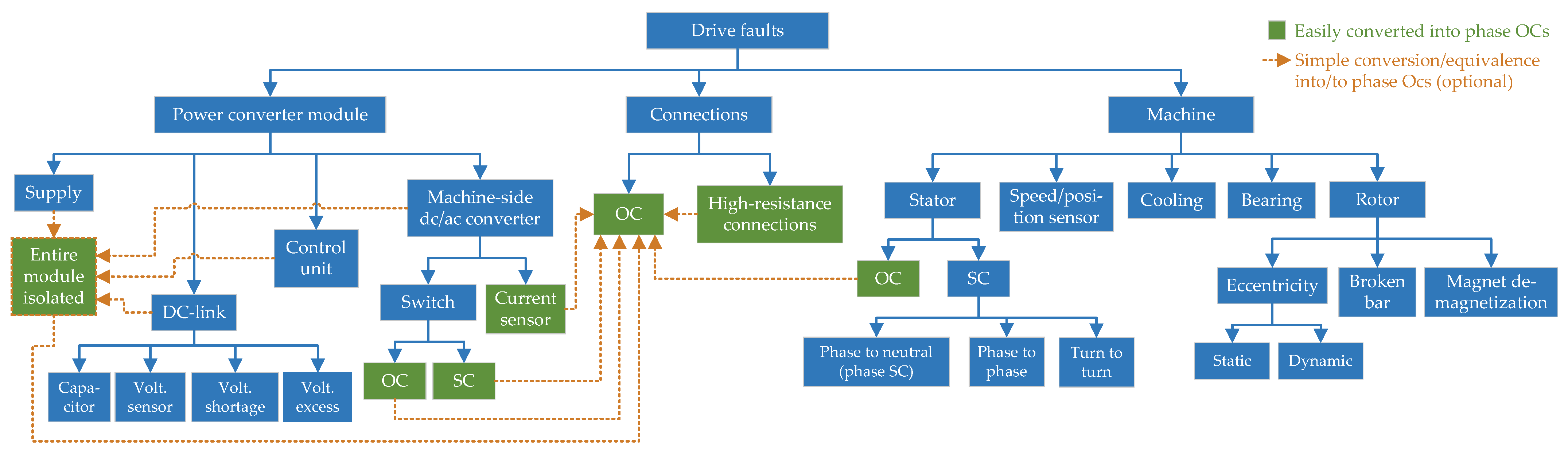
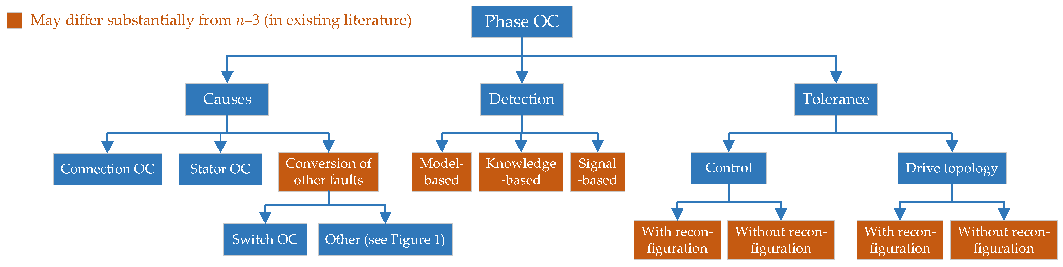
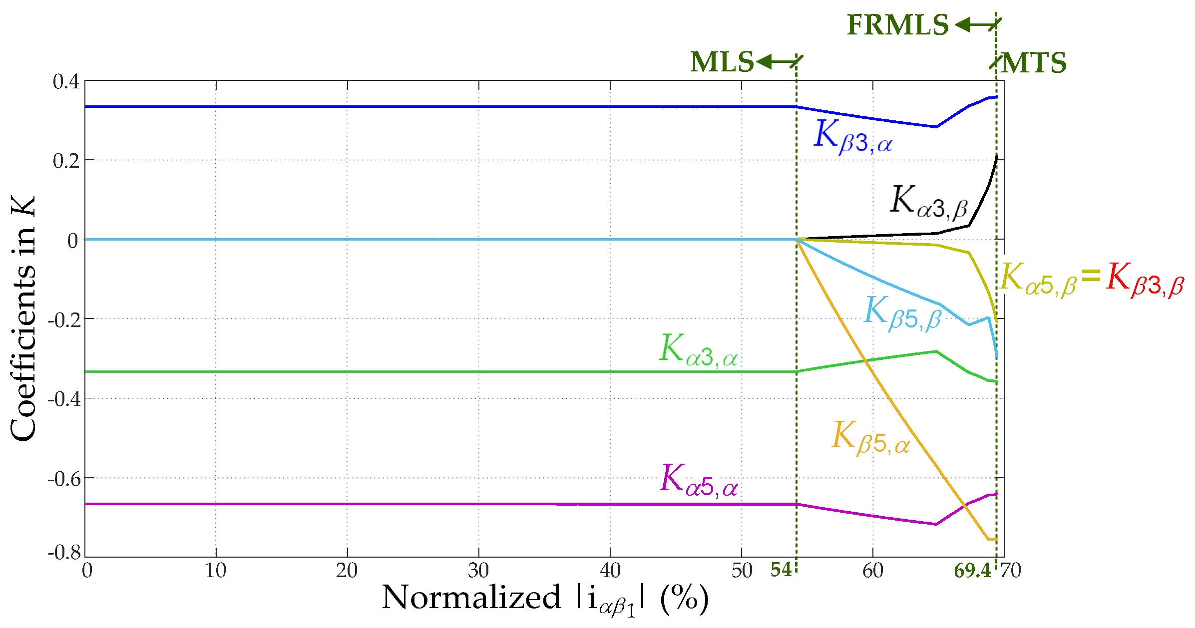
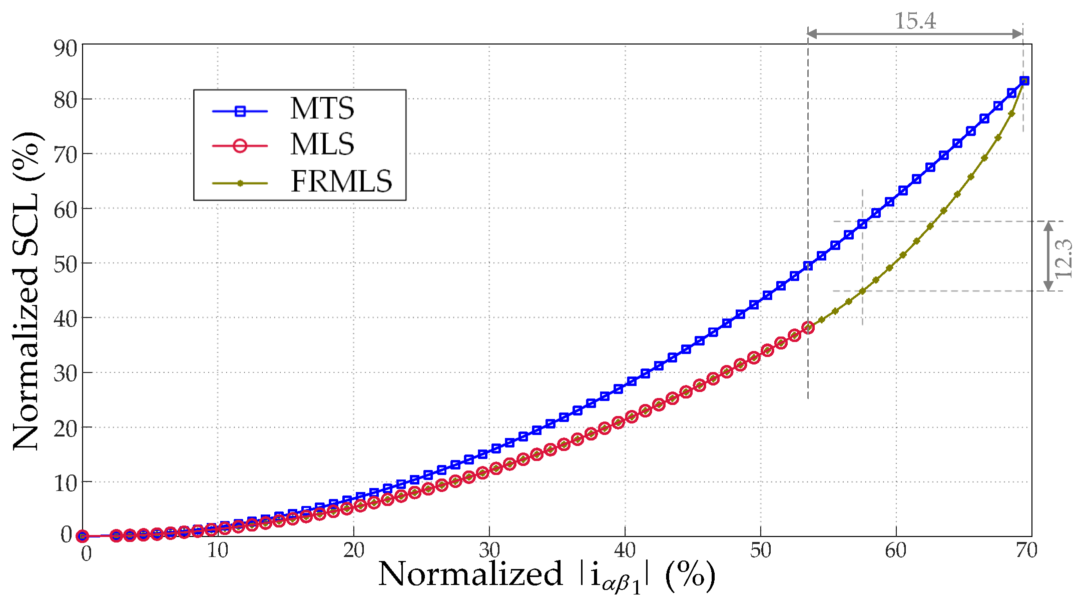
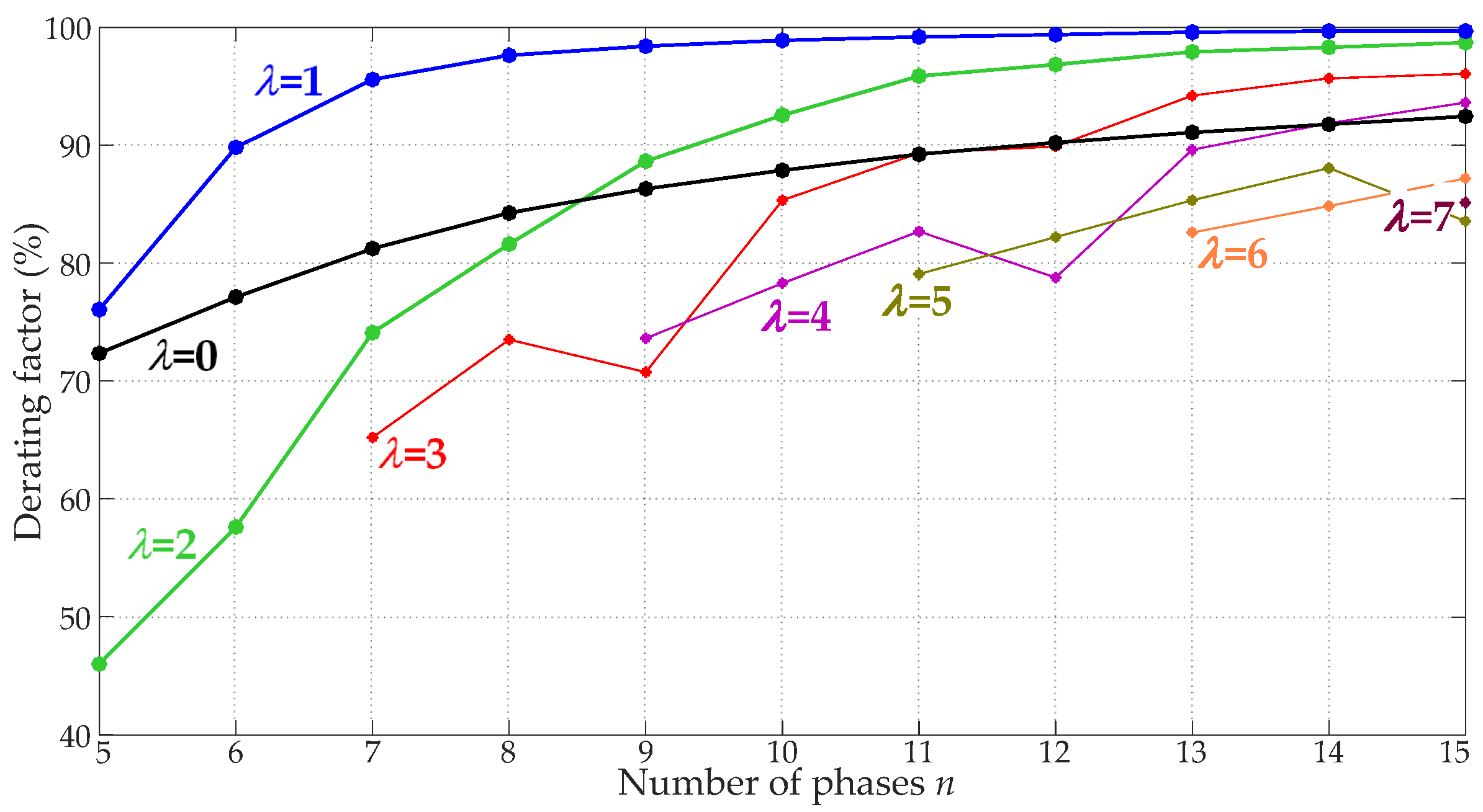
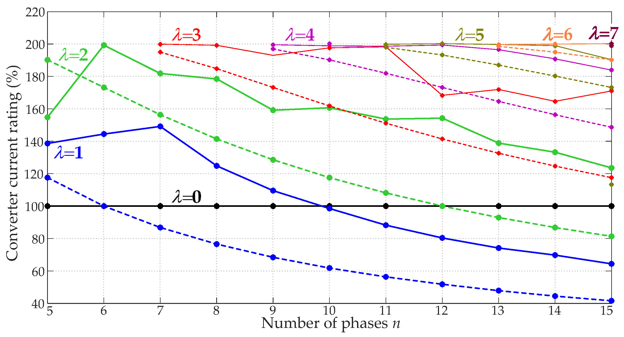
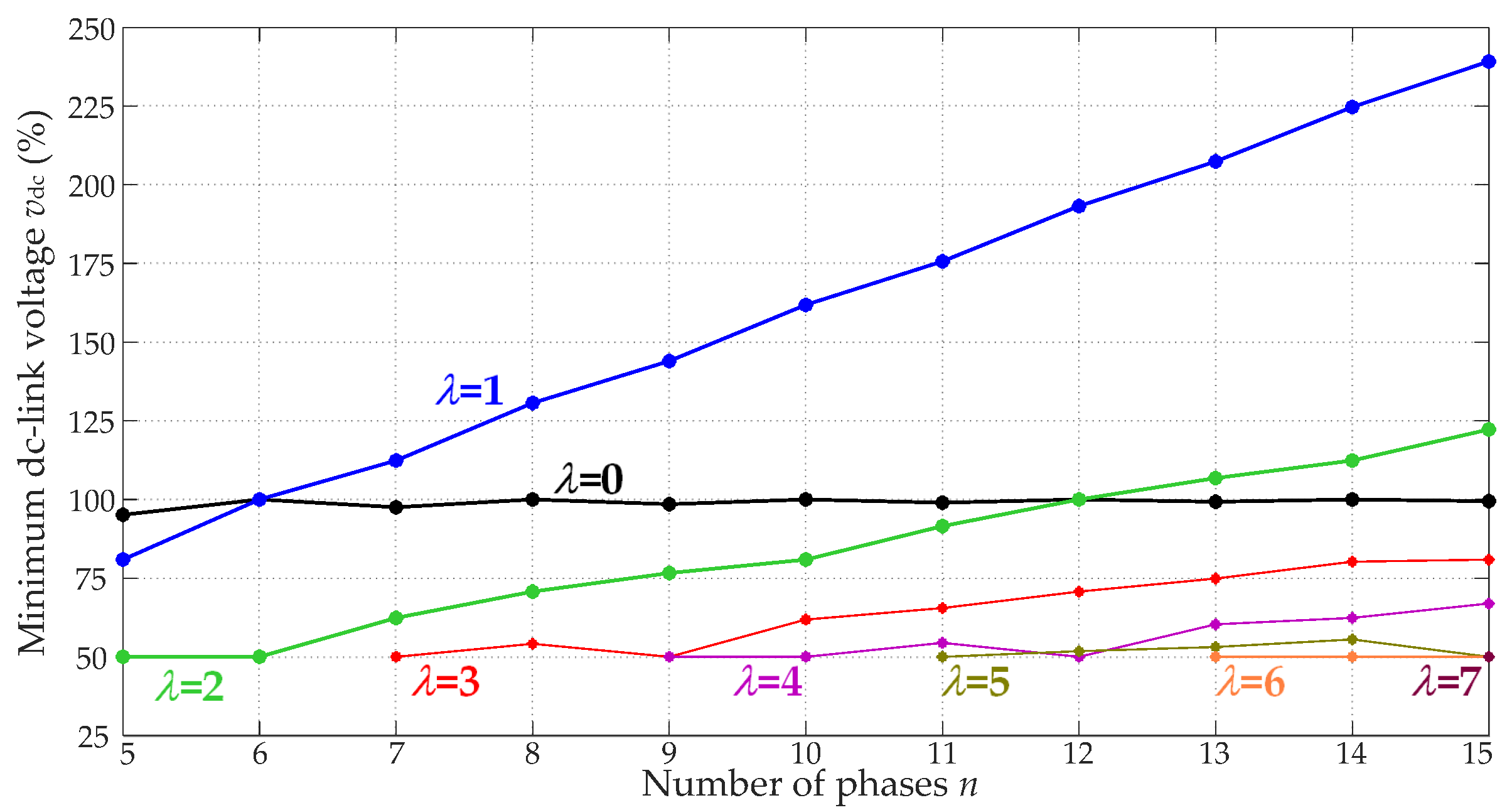
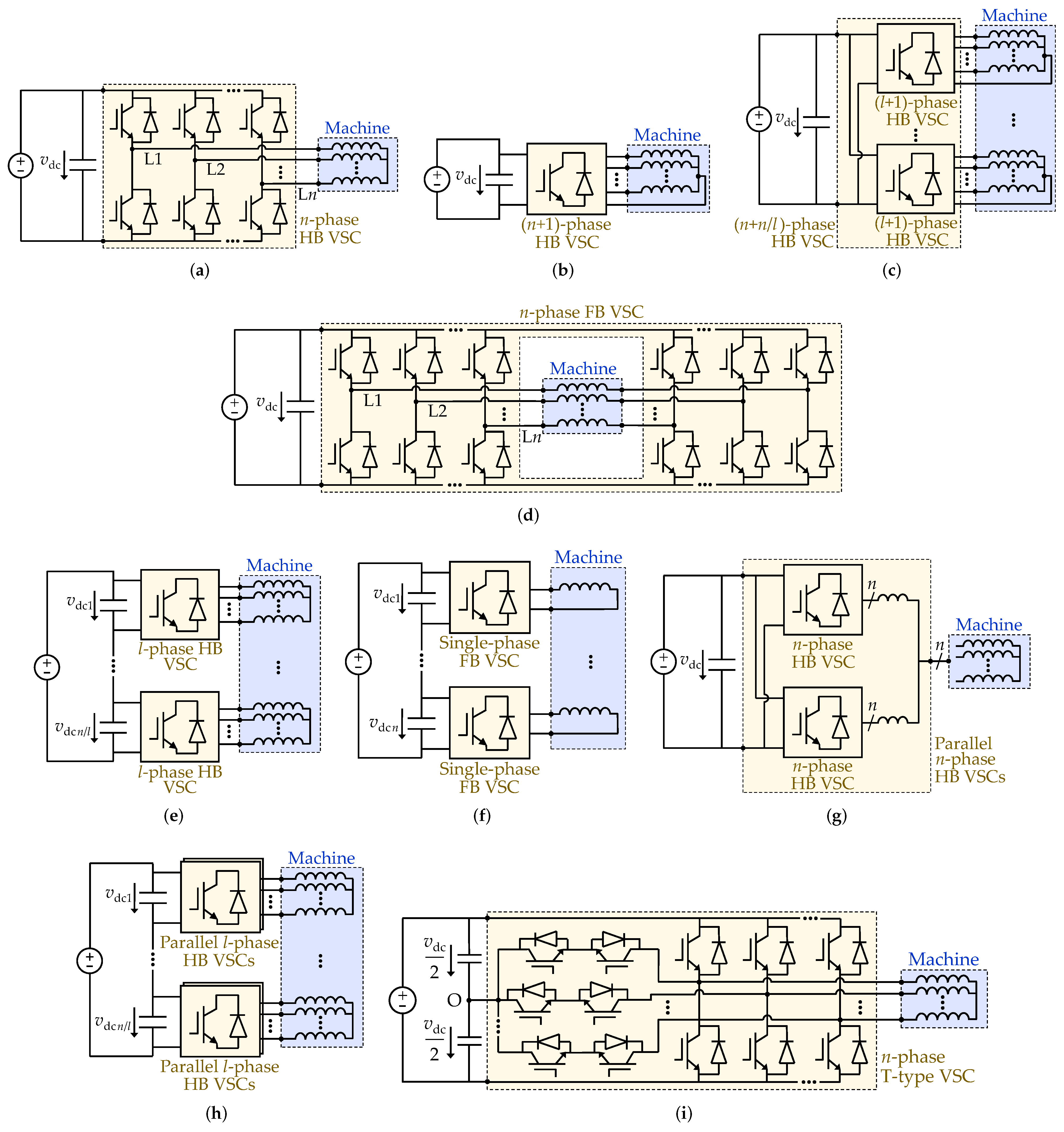
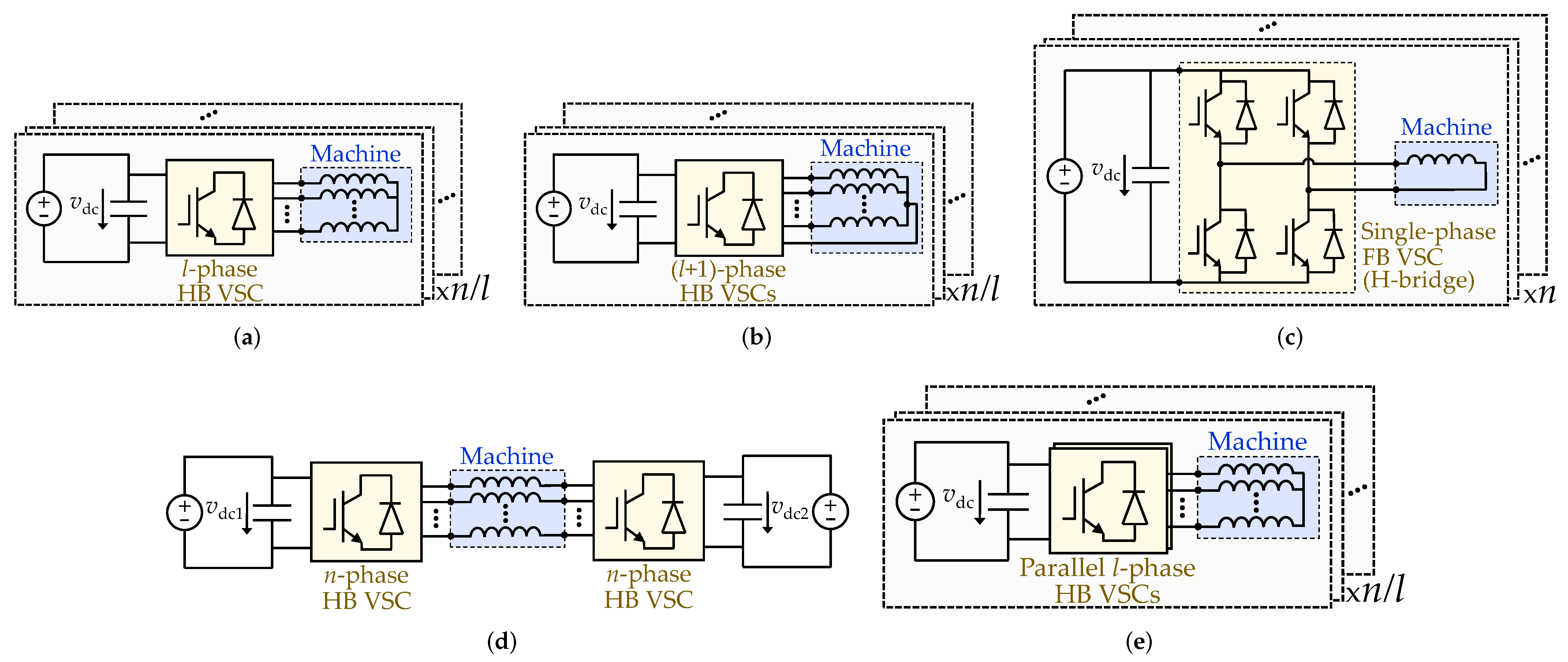
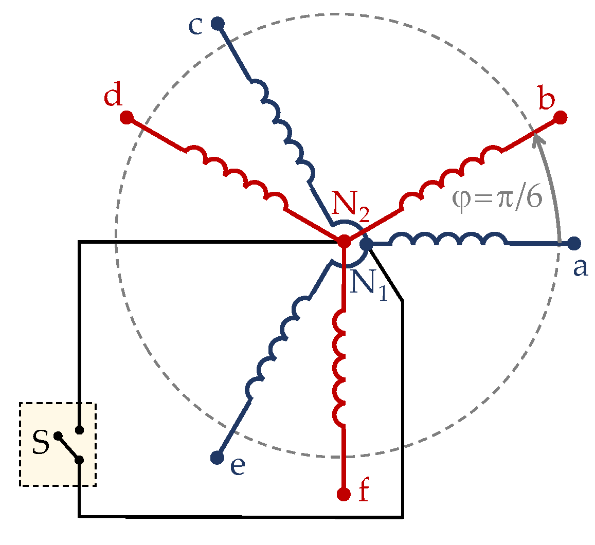
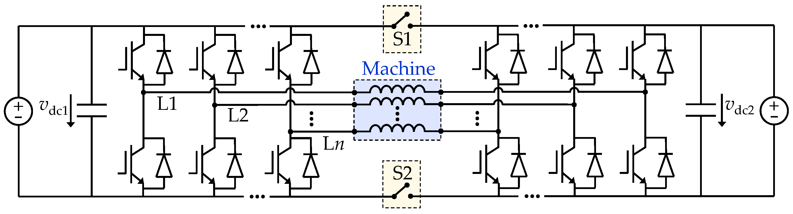
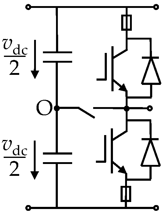
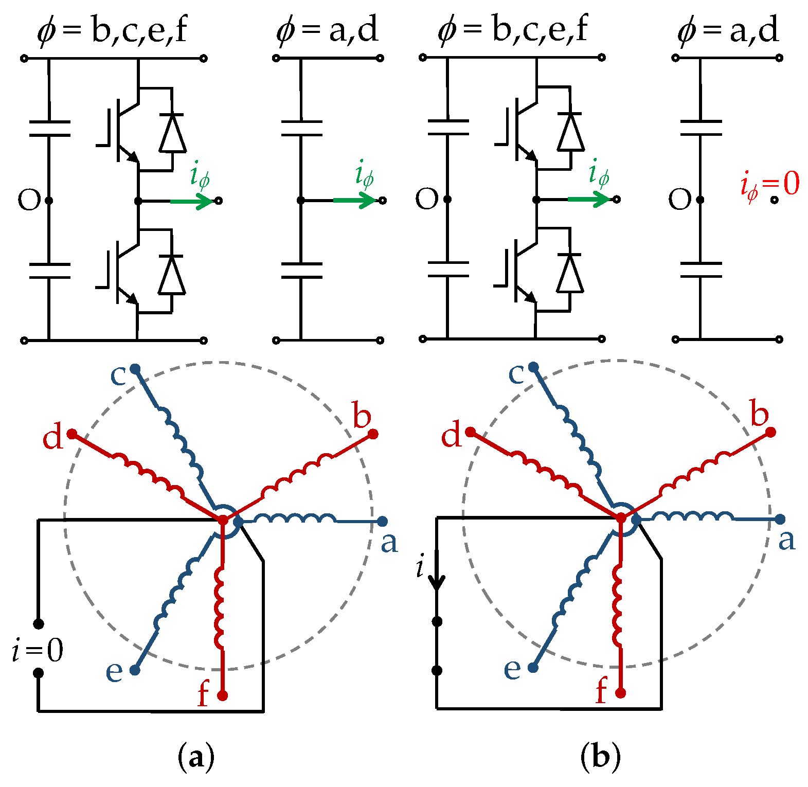
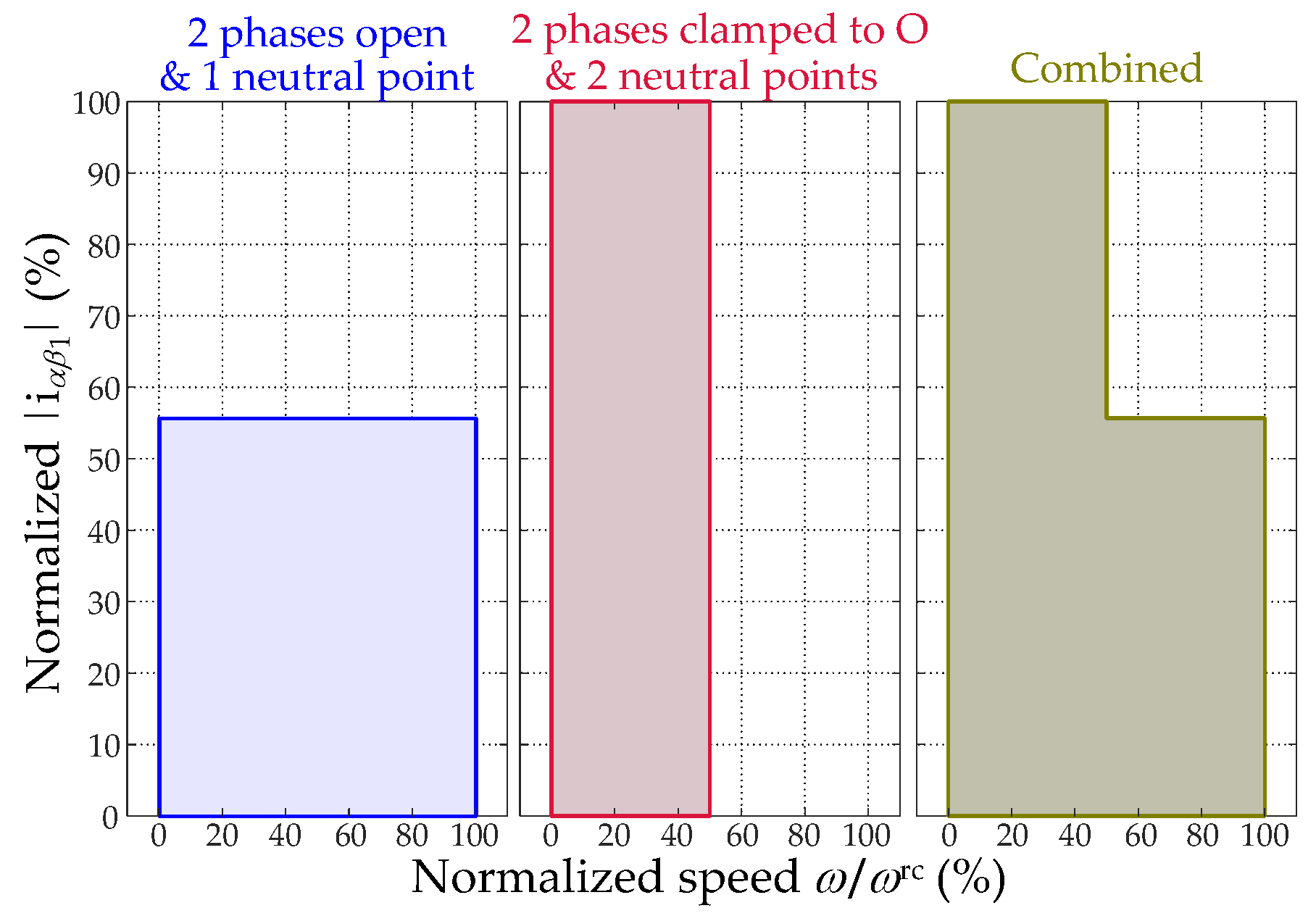
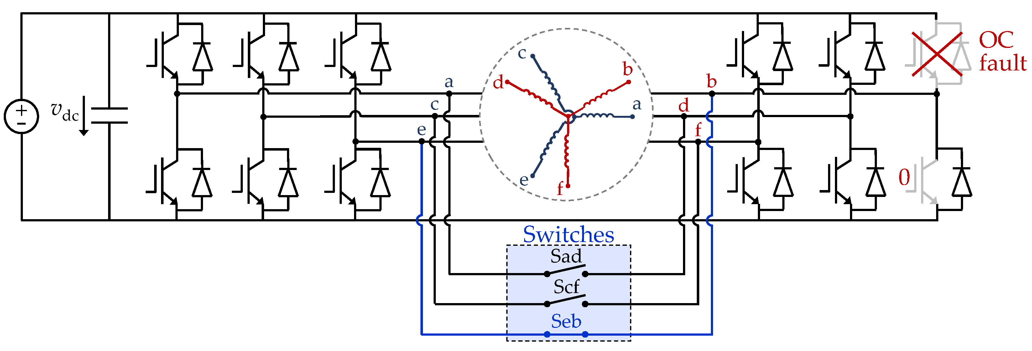
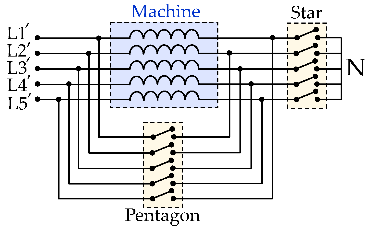
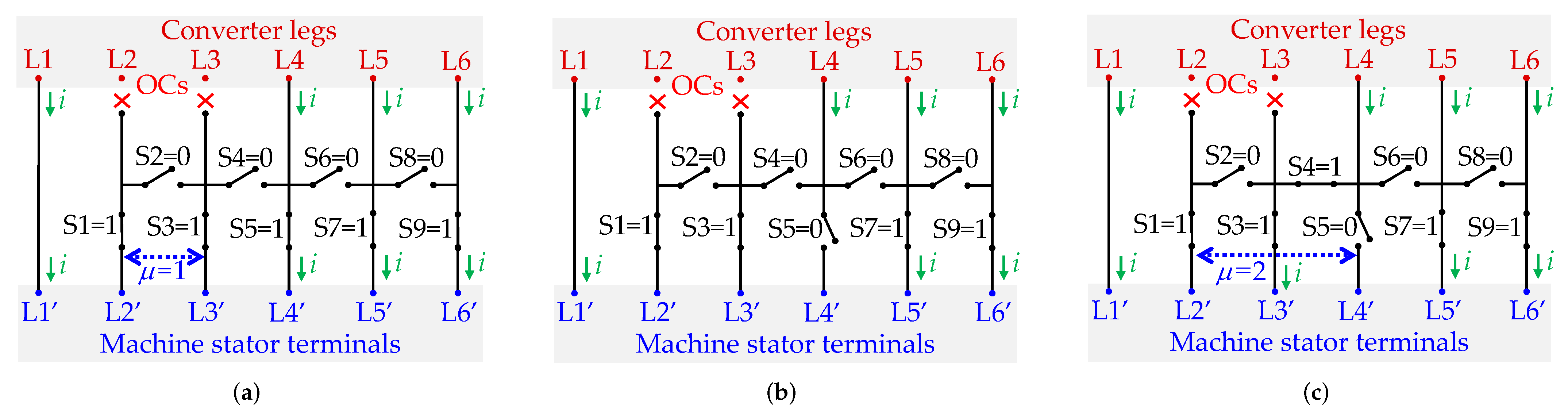
Figure 1. Types of faults in an ac drive.
Machines 10 00221 g001
Figure 2. Causes, detection methods, and tolerance approaches for phase OC faults (or similar) in multiphase drives.
Machines 10 00221 g002
Figure 3. Coefficients in K [see (1)] for generating the VSD current references according to the FRMLS as a function of | i α β 1 | (normalized by rated), for the scenario of OC in phase a of a six-phase machine with asymmetrical WSA, star connection, and single neutral point. The FRMLS coefficients match those of MLS for | i α β 1 | < 54 % , and those of MTS for | i α β 1 | = 69.4 % .
Machines 10 00221 g003
Figure 4. Comparison of the MLS, MTS, and FRMLS in terms of SCL as a function of | i α β 1 | (normalized by rated), for the scenario of OC in one phase of a six-phase machine with asymmetrical WSA, star connection, and single neutral point.
Machines 10 00221 g004
Figure 5. DF depending on n and the stator phase connection λ , for single-line OC [22].
Machines 10 00221 g005
Figure 6. Required VSC line-current rating, normalized by machine phase-current rating, depending on n and the stator phase connection λ , for healthy drive (dashed) or single-line OC (solid) [22].
Machines 10 00221 g006
Figure 7. Minimum dc-link voltage (without overmodulation), normalized by twice the magnitude of back-EMF, depending on n and the stator phase connection λ [22].
Machines 10 00221 g007
Figure 8. VSC non-modular topologies in multiphase ac drives, ignoring postfault reconfiguration. (a) Single n-phase HB VSC. (b) Single (n+1)-phase HB VSC. (c) Single (n+ n / l )-phase HB VSC. (d) Single n-phase FB VSC for open-end windings. (e) Series dc-side connection of l-phase HB VSCs. (f) Series dc-side connection of single-phase FB VSCs. (g) Parallel n-phase HB VSCs. (h) Series dc-side connection of parallel l-phase HB VSCs. (i) Single n-phase T-type three-level VSC.
Machines 10 00221 g008
Figure 9. VSC modular topologies in multiphase ac drives, ignoring postfault reconfiguration. (a) Multiple independent l-phase HB VSCs. (b) Multiple independent (l+1)-phase HB VSCs. (c) Multiple independent single-phase FB VSCs (H-bridges). (d) Dual n-phase HB VSC for open-end windings. (e) Multiple independent parallel l-phase HB VSCs.
Machines 10 00221 g009
Figure 10. Stator scheme of a six-phase machine with asymmetrical WSA and a bidirectional switch S between the neutral points N 1 and N 2 of the two three-phase winding sets [24].
Machines 10 00221 g010
Figure 11. Open-end winding topology with bidirectional switches (S1 and S2) to alternate between dual n-phase HB VSC and single n-phase FB VSC.
Machines 10 00221 g011
Figure 12. Schematic of two-level VSC dc link and an arbitrary leg, with a bidirectional switch S to connect to the dc-link midpoint O and a fuse in series with each IGBT [24].
Machines 10 00221 g012
Figure 13. Reconfiguration strategy proposed in [24] based on alternating between phases open or clamped to O, considering the particular case with IGBT OC faults in phases a and d, and with bidirectional switch between neutral points [24]. (a) Speed under half its rating ( ω < ω rc / 2 ). (b) Speed over half its rating ( ω > ω rc / 2 ).
Machines 10 00221 g013
Figure 14. A | i α β 1 | -speed region under IGBT OC faults in phases a and d of an asymmetrical six-phase machine, if both phases are kept open with single neutral point (left), both of them are clamped to O with separate neutral points (center), and for the method based on alternating between these modes depending on the speed (right) [24].
Machines 10 00221 g014
Figure 15. Topology with bidirectional switches so that a leg can be shared by two phases [224].
Machines 10 00221 g015
Figure 16. Five-phase topology with bidirectional switches to alternate between star and pentagon stator connections [226].
Machines 10 00221 g016
Figure 17. Reconfiguration following the sequence (ac) from μ = 1 to μ = 2 by using an electric scheme between VSC and machine in order to improve the postfault performance for n = 6 , λ = 0 (star), or λ = 1 (hexagon), and symmetrical WSA, under OCs in VSC legs/lines L2 and L3 [23].
Machines 10 00221 g017
Table 1. General classification of references about tolerance to phase/switch OCs in multiphase drives. Survey papers and books are not included in this table.
ReferencesDetectionTolerant ControlTolerant Drive Topologies
With ReconfigurationWithout Reconfiguration *With Reconfiguration Without Reconfiguration
[18,43,44,45,46,47,48,49,50,51,52,53,54,55,56,57,58,59,60,61,62]××××
[63,64,65,66,67,68,69,70,71,72]×××
[15]××
[73,74]×××
[75]×××
[5,9,16,17,76,77,78,79,80,81,82,83,84,85,86,87,88,89,90,91,92,93,94,95,96,97,98,99,100,101,102,103,104,105,106,107,108,109,110,111,112,113,114,115,116,117,118,119,120,121,122,123,124,125,126,127,128,129,130,131,132,133,134,135,136,137,138,139,140,141,142,143,144,145,146,147,148,149,150,151,152,153,154,155,156,157,158,159,160,161,162,163,164,165,166,167,168,169,170,171,172,173,174,175,176,177,178,179,180,181,182,183,184,185,186,187,188,189,190,191,192,193,194,195,196,197,198,199,200,201,202,203,204,205,206,207,208,209,210,211,212,213,214,215,216,217,218]××××
[219]×××
[220]××
[24,25,221,222,223,224,225,226,227]×××
[23,228]××
[12,13,14,20,21,22,229,230,231,232,233,234,235,236,237,238,239,240,241,242,243,244,245,246,247,248,249,250,251,252]×××
[19,253,254,255,256,257,258,259]××××
[260]×××
[261,262,263,264]××××
[231,265,266,267,268,269,270,271,272,273,274,275,276,277,278,279,280,281,282,283,284,285,286]××××
Section233.64.24.1
* Using V/f control without reconfiguration is not included, because of the significant torque ripple. Isolating a faulty VSC leg/switch by a fuse or bidirectional switch is not considered reconfiguration. ✓is assigned to this column only if significant details are given about the postfault performance depending on the topology.
Table 2. Methods for detecting phase/switch OC faults (Section 2) in multiphase applications in the literature.
ReferencesElectric DriveType ofRequirementsOCFault ph.AdditionalMonitored
ApproachR1R2R3R4R5TypeLocationFaults DetectedCurrent
Salehifar et al. [43]5-ph. PMSMMBYesYesYesYesNoPh./sw.YesNoPhase
Salehifar et al. [63]5-ph. PMSMMBYesYesNoYesNoPh./sw.YesNoPhase
Salehifar et al. [64]5-ph. PMSMMBYesYesYesYesNoPh./sw.YesSwitch SCPhase
Salehifar et al. [65]5-ph. PMSMMB & SBYesNo *YesYesNoPh./sw.YesNoPhase
Gonçalves et al. [44]Asym. 6-ph. PMSMMBYes YesYesNoPhaseYesHigh-resistancex-y
Gonçalves et al. [44]Asym. 6-ph. PMSMSBYes YesYesYesPhaseYesHigh-resistancex-y
Torabi et al. [45]5-ph. IMMB & KBYesYesNoYesYesPh./sw.YesNoPhase §
Torabi et al. [46]NPC 5-ph. IMMB & KBYesYesNoYesYesPh./sw.YesNoPhase §
Olivieri [66]5-ph. PMSMKBYesNoNoYesNoPhaseYesNo α 1 - β 1
Yao et al. [47]5-ph. PMSMKBYesNoNoNoNoPhaseYesCurrent sensor d 1
Meinguet et al. [48]5-ph. PMSMSBYesNoYesYesYesPh./sw.YesNoPhase
Various [49,50,67,68,69]AnySBYesNoYesYesYesPhaseYesNoPhase
Jiang et al. [70]Sym. 6-ph. PMSMSBYesNoYesYesYesPhaseYesStator SCPhase
Mesai-Ahmed et al. [51]Asym. 6-ph. IMSBYesNoYesYesYesPh./sw.YesNoPhase
Wen et al. [52]3-sector 9-ph. PMSMSBYesYesYesNoNoPhaseNoNoPhase
Meinguet et al. [53]5-ph. PMSMSBYesNoYesNoNoPhaseNoNo α 1 - β 1
Duran et al. [54]Asym. 6-ph. IMSBYesYesYesYesYesPhaseYesNo α 1 - β 1 & a x-y
Gonzalez-Prieto et al. [71]5-ph. IMSBYesYesYesYesYesPh./sw.YesNo α 1 - β 1 & x-y
Kong et al. [55]5-ph. PMSMSBYesYesYesYesYesPh./sw.YesNo α 1 - β 1 & x-y
Farag et al. [56]Sym. 6-ph. IMSBYesNoYesYesYesPh./sw.YesHigh-res., barsPh., α 1 - β 1 & x-y
Arafat et al. [57]5-ph. PMSMSBYes YesYesYesPhaseNoHigh-resistance α 1 - β 1 & x-y
Chen et al. [58]5-ph. PMSMSBYesNoNoYesYesPh./sw.YesNo α 1 - β 1 & x-y
Trabelsi et al. [59]5-ph. PMSMSBYesYesYesYesYesPh./sw.YesNoPh., α 1 - β 1 & x-y
Trabelsi et al. [60]5-ph. PMSMSBYesYesYesYesYesPh./sw.YesNoPh., α 1 - β 1 & x-y
Gonçalves et al. [61]Asym. 6-ph. PMSMSBYesYesYesYesYesPhaseYesNox-y
Gonçalves et al. [62]Asym. 6-ph. PMSMSBYesYesYesYesYesPhaseYesHigh-resistancex-y
Moraes et al. [75]Series Sym. 6-ph. PMSMsSBYesYesYesYesYesPh./sw.YesNo α 1 - β 1
Wang et al. [15]T-type VSC, As. 6-ph. PMSMSBNoNo *NoYesYesPh./sw.YesSwitch SCx-y
Guo et al. [18]Sym. 6-ph. PMSMSBYesYesYesYesYesSwitchYesNo α 1 - β 1 & x-y
Wang et al. [72]Asym. 6-ph. PMSMSBYesNo *YesYesYesPh./sw.YesVarious sensorsx-y & ph.
Salas-Biedma et al. [74]5-ph. IMSBYesYesYesYesNo Ph./sw.YesHigh-resistance α 1 - β 1 & x-y
Entrambasaguas et al. [73]Asym. 6-ph. IMSBYesYesYesYesYesPhaseNoNo α 1 - β 1 & x-y
* A fundamental period is required for fault-type identification or location, although its occurrence is detected sooner. The detection time is not provided. The detection of high-resistance connections, which is the main contribution with respect to [71], is based on the absence of closed-loop x-y control. § The gate drive signals are also monitored.
Table 3. Classification of references (and paper sections/tables) about control methods for tolerating phase/switch OCs (Section 3) in multiphase applications in the literature.
Type of Control (VSD, Controller, Current References, etc.)SectionTableReferences
Using n-dimensional VSD3.1.14Many
Using reduced-order VSD3.1.24Many
Using multiple three-phase VSD3.1.34[67,69,70,92,94,95,96,97,99,100,101,114,222,244,245,253]
V/f control3.25[76,77,226,228,229,230,231,249,274,275]
DTC based on hysteresis and LUTs3.3.16[74,78,79,80,81,82,83,258]
DTC based on FCS-MPC3.3.26[84,86]
DTC based on PI + predictive control + PWM3.3.36[12,13,72,85,87]
DTC based on FCS-MPC + PWM3.3.46[88]
DFC3.3.56[91,92]
RFOC based on current d 1 - q 1 PI control without x-y control using full-order VSD3.4.1.17[19,89,90,93,255]
RFOC based on multiple l-phase current d-q PI control3.4.1.27[67,69,70,94,95,96,97,99,114,222,244,253,260]
RFOC based on current d 1 - q 1 PI control using reduced-order VSD3.4.1.37[98,102,103,104,105,106,107,108,109,110,111,112,113,115,116,117,118,119,120,121,122,123,124,208,221]
RFOC based on current dual-PI or PR control using full-order VSD3.4.1.47[5,17,20,21,22,23,24,25,80,81,125,126,127,128,129,130,131,132,133,134,135,136,137,138,139,140,227,232,233,234,237]
RFOC based on current d-q PI control per plane using full-order VSD3.4.1.57[141,142,143,144,145,146,224,237,238,239]
RFOC based on current d 1 - q 1 PI and x-y stationary PI control using full-order VSD3.4.1.67[15,147,162,225]
RFOC based on current per-phase PI or PR control3.4.1.77[63,66,148,149,150,151,152,153,154,155,156,157,242]
RFOC based on current FCS-MPC3.4.28[9,64,65,71,73,80,134,158,159,160,161,163,164,165,166,167,168,169,256,257]
RFOC based on current deadbeat control3.4.39[14,16,170,171,172,210,259]
RFOC based on current hysteresis control3.4.4[81,173,174,175,176,177,178,179,201,240,241,260]
RFOC based on current sliding-mode control3.4.510[181,182,183,184,185,186]
RFOC based on current fuzzy-logic control3.4.611[185,254]
RFOC generation of current references with sinusoidally distributed windings3.5.112; 13Many
RFOC generation of current references considering space harmonics3.5.214[98,107,109,118,119,121,122,133,143,144,148,150,152,153,154,156,176,177,178,179,180,181,182,183,199,200,201,202,203,204,209,219,240,241,242,243,251,252]
RFOC generation of current references using an adaptive outer loop3.5.315[67,68,69,105,106,185,186,219,253]
Control with reconfigurationless tolerance to phase OCs3.616[19,73,74,219,220,253,254,255,256,258,259]
Table 4. VSD approaches for drives tolerant to phase OCs (Section 3.1) in multiphase applications in the literature.
VSD TransformVSD ReconfigurationMachine Model Change *Coupling between SubspacesCurrent Reference ReconfigurationCurrent Controller Reconfiguration
PrefaultPostfault3-ph. Module Off1 Phase OC
n-dimensionalNoneNoneLow/noneComplexComplexComplexSimple/none
Reduced-orderComplexComplex/noneComplex/noneComplex/noneComplex/noneComplex/none
Multiple 3-phaseNoneNoneComplexComplex (simple change)Very simpleVery complexSimple/very simple
* Other than coupling between subspaces.
Table 5. Methods based on open-loop V/f control for tolerating phase OCs (Section 3.2) in multiphase applications in the literature.
ReferencesMachinePostfault Reconfiguration
n WSARotor
Abdel-Khalik et al. [76,226,229,230]6Asym.IMReferences for closed-loop x-y current control
Melo et al. [228]6Asym.IMVoltage FF
Melo et al. [249]6Asym.IMOpen-loop voltage references
Paredes et al. [77]6No-ph.IMDisable 3-phase set
Abdel-Khalik et al. [231]9Asym.IMDisable 3-phase set
Table 6. Methods based on direct torque/flux control for tolerating phase OCs (Section 3.3) in multiphase applications in the literature.
ReferencesMachineNumber of VSC LevelsType of ControlPostfault Reconfiguration
nWSARotor
Zhou et al. [78]6Sym.PMSM2Hysteresis DTCVSD & LUT
Bermudez et al. [79]5Sym.IM2Hysteresis DTCVSD & LUT
Barrero et al. [74,258]5Sym.IM2Hysteresis DTCNone
Chikondra et al. [82]5Sym.IM2Hysteresis DTCVSD & LUT
Zhou et al. [83]5Sym.PMSM2Hysteresis DTCVSD, LUT, & disturbance observer
Zhou et al. [84]3,6Sym.PMSM2FCS-MPC DTCMachine model for flux prediction
Huang et al. [86]5Sym.PMSM2FCS-MPC DTCVSD, SV preselection, & x-y current refs.
Zhang et al. [85]5Sym.PMSM2PI + pred. + SV PWM DTCPWM
Zhou et al. [87]5Sym.PMSM2PI + pred. + SV PWM DTCVSD & voltage FF
Wang et al. [12]6Asym.PMSM3PI + pred. + SV PWM DTCFF (phase OC) or PWM (switch OC)
Wang et al. [13]6Asym.PMSM3PI + pred. + SV PWM DTCFF (phase OC) or PWM (switch OCs)
Wang et al. [72]6Asym.PMSM3PI + pred. + SV PWM DTCFF (phase OC)
Huang et al. [88]5Sym.PMSM2FCS-MPC + SV PWM DTCVSD, SV preselection, & x-y current refs.
Bojoi et al. [91]6Asym.IM2PWM DFCDisable 3-phase set
Rubino et al. [92]6Asym.IM2Deadbeat + PWM DFCDisable 3-phase set
Table 7. Methods based on RFOC with current PR or d-q PI control for tolerating phase OCs (Section 3.4.1) in multiphase applications in the literature.
ReferencesMachineNo.
ph.
OCs
Postfault
VSD
Transform
Postfault Current ControlSpace HarmonicsSalientPostfault
Reconfiguration
(Besides PI/PR Control)
nWSARotorPIPR/Dual-PI *
Che et al. [89]6Sym.IM1Full d 1 - q 1 No1NoVoltage FF
Liu et al. [90]5Sym.PMSM1Full d 1 - q 1 No1NoSV PWM
Chen et al. [93]5Sym.PMSM1,2Full d 1 - q 1 No1NoSV PWM
Gonzalez-Prieto et al. [19,255]6Asym.IM1,2Full d 1 - q 1 No1NoNone (not control either)
[67,69,70,94,95,244]AnyAnyAny3,6Mult. 3-ph.Mult. d-qNo1No/yesDisable 3-phase set
Jiang et al. Jiang2019TIE6Sym.PMSM3Mult. 3-ph.Mult. d-qNo1NoDrive topology
Jung et al. Jung2012TIA9Sym.PMSM3Mult. 3-ph.Mult. d-qNo1NoDisable 3-phase set
Rubino et al. [97]9Asym.IM3Mult. 3-ph.Mult. d-qNo1NoDisable 3-phase set
Kuang et al. [260]15Asym.PMSM1Mult. 5-ph.Mult. d-qNo1NoNone (not control either)
Xu et al. [253]6Sym.PMSM1,2Mult. 3-ph.Mult. d-qNo1NoNone (not control either)
Shamsi-Nejad et al. [99]6No-ph.PMSM1,3Mult. 3-ph.Mult. d-qNo1NoCurrent references
Li et al. [114]6Asym.PMSM1,3Mult. 3-ph.NoMult. α - β 1YesCurrent references
Souza et al. [102]9Sym.IM1-3Reduced d 1 - q 1 No1NoVSD & voltage FF
Ryu et al. [110]5Sym.PMSM1Reduced d 1 - q 1 & xNo1YesVSD, v FF, & i refs.
Zhou et al. [103]5Sym.PMSM1Reduced d 1 - q 1 & xNo1NoVSD
Chen et al. [104]5Sym.PMSM2Reduced d 1 - q 1 No1NoVSD
Priestley et al. [111]5Sym.PMSM1Reduced d 1 - q 1 & x-yNo1,3YesVSD
Fan et al. [112]5Sym.PMSM1Reduced d 1 - q 1 & x-yNo1NoVSD
Tian et al. [105]5Sym.PMSM1Reduced d 1 - q 1 & xNo1,3YesVSD & i refs.
Tian et al. [106]5Sym.PMSM2Reduced d 1 - q 1 d 1 - q 1 1,3YesVSD
Liu et al. [107]5Sym.PMSM1,22 reduced d 1 - q 1 (& x) No1,3YesVSD & i refs.
Tian et al. [108]5Sym.PMSM2Reduced d 1 - q 1 d 1 - q 1 1,3YesVSD, v FF, & PWM
Tian et al. [109]5Sym.PMSM1Reduced d 1 - q 1 & x d 1 - q 1 & x  § , 1,3YesVSD, v FF, & i refs.
Cheng et al. [115]5Sym.PMSM1Reduced d 1 - q 1 & xNo1,3NoVSD, v FF, & i refs.
Xu et al. [113]5IM1Reduced d 1 - q 1 & xNo1,3NoVSD, v FF, & i refs.
Kong et al. [98]5Sym.IM1Reduced d 1 - q 1 & x-y  No1,3NoVSD & i refs.
Hu et al. [117]6Asym.PMSM1Reduced d 1 - q 1 & xx1YesVSD & voltage FF
Hu et al. [116]6Asym.PMSM1Reduced d 1 - q 1 & xx1VSD, v FF, & i refs.
Xiong et al. [118]5Sym.PMSM1Reduced d 1 - q 1 & x d 1 - q 1 & x1,3NoVSD & i refs.
Xiong et al. [119]5Sym.PMSM2Reduced d 1 - q 1 d 1 - q 1 1,3NoVSD & i refs.
Liang et al. [221]6No-ph.PMSM1Reduced d 1 - q 1 & x-y  d 1 - q 1 & x-y  , § 1,3NoVSD, v FF, PWM, i refs., & drive
Geng et al. [120]6Asym.IM1-3Reduced d 1 - q 1 x § 1NoVSD
Qiu-Liang et al. [121]5Sym.PMSM12 reduced 3 per VSDNo1,3NoVSD & i refs.
Vu et al. [122]7Sym.PMSM12 reduced 5 per VSDNo1,3,9NoVSD
Chen et al. [124]5Sym.PMSM1,2Reduced d 1 - q 1 (& x) No1YesVSD & i refs.
Chen et al. [123]5Sym.PMSM1,2Reduced d 1 - q 1 (& x) No1YesVSD & SV PWM
Eldeeb et al. [25]6Asym.PMSM1Full d 1 - q 1 d 1 - q 1 & x-y1-13YesCurrent references
[5,17,21,22,23,24,125,126,127,128,129,130,131,132,227,232,233,234]AnyAnyAnyAnyFullNo α 1 - β 1 & x-yAnyNo/yesCurrent references
[20,80,81,133,134,135,136,137,138,139,140,237]AnyAnyAnyAnyFull d 1 - q 1 x-yAnyNo/yesCurrent references
Duran et al. [237,238,239]6Asym.IM3Full d 1 - q 1 & x-y  No1NoCurrent references
Zoric et al. [141]9Asym.IM3,6Full d 1 - q 1 & x-y  No1,29,31NoCurrent references
Sala et al. [142]12Asym.IM3Full d 1 - q 1 & x-y  No1NoCurrent references
Locment/Vu et al. [143,144]7Sym.PMSM1,2Full d 1 - q 1 & x-y  No1,3,9NoCurrent references
Feng et al. [145,146]6AsymPMSM1Full d 1 - q 1 & x-y  NoAnyNo/yesCurrent references
Hu et al. [224]6Asym.PMSM1Full d 1 - q 1 & x-y  No1NoDrive topology
Baudart et al. [162]6Sym.PMSM1Full d 1 - q 1 & x-yNo1Noi refs.
Jing et al. [225]6Asym.PMSM1Full d 1 - q 1 & x-yNo1YesDrive topology
Li et al. [147]6No-ph.PMSM1,2Full d 1 - q 1 & x-y d 1 - q 1 1NoVoltage FF
Wang et al. [15]6Asym.PMSM1Full d 1 - q 1 & x-yNo1NoSV PWM
Wang et al. [15]6Asym.PMSM1Full d 1 - q 1 & x-yNo1NoVSD & i refs.
[148,149,150]AnyAnyAnyAnyNonePer phaseNoAnyNo/yesCurrent references
[63,152,153,154,155,242]AnyAnyAnyAnyNoneNoPer phaseAnyNo/yesCurrent references
Kong et al. [156]5Sym.IM1,2NonePer phasePer phase1,3NoCurrent references
* The PR or dual-PI control is not indicated if it does not yield infinite gain at the frequencies of the fundamental or considered space harmonics and the proportional gain is already part of a PI controller. Two reduced-order VSD transforms are used in parallel, for the first- and third-order harmonics. The controller in the secondary axis x is omitted for double-phase OCs. The x-y control is implemented in a synchronous frame. § Despite being implemented in stationary frame, the PR or dual-PI control in x-y subspaces yields infinite gain just at harmonics, not at the fundamental. The resonant parts are implemented as repetitive control.
Table 8. Methods based on RFOC with current FCS-MPC for tolerating phase OCs (Section 3.4.2) in multiphase applications in the literature.
ReferencesMachineNo. VSC LevelsFixed Switch. Freq.SVs Applied per Sampl. PeriodMinimized Error in Cost FunctionPostfault Reconfiguration *
nWSARotor
Pham et al. [158]5Sym.PMSM3No1Torque & VSD curr.Current references
Duran et al. [9,71,134,163]5Sym.IM2No1VSD currentsVSD & current refs.
Liu et al. [159]5Sym.PMSM2No1VSD currentsVSD
Luo & Liu [165]6Asym.PMSM2No1VSD currentsPredicted SVs & current refs.
Lu et al. [161]6Asym.PMSM2No1Phase currentsVSD & current refs.
Lu et al. [164]6Asym.PMSM2No2Phase currentsPer-phase machine model & current refs.
Salehifar et al. [64]5Sym.PMSM2No1VSD voltagesPer-phase machine model & current refs.
Salehifar et al. [65]5Sym.PMSM2No1Phase currentsPer-line machine model & current refs.
Huang et al. [160]5Sym.PMSM2No2VSD currentsVSD & current refs.
Gonzalez-Prieto et al. [73,256,257]6Asym.IM2No2 α 1 - β 1 currentNone
Tao et al. [166]5Sym.PMSM2No2 α 1 - β 1 currentVSD & virtual SVs
Tao et al. [167]5Sym.PMSM2Yes5 α 1 - β 1 currentVSD, virtual SVs, & back-EMF compensation
* Changing the VSD transform also implies that the VSC voltage vectors evaluated in the cost function in VSD coordinates are modified accordingly.
Table 9. Methods based on RFOC with current deadbeat control for tolerating phase OCs (Section 3.4.3) in multiphase applications in the literature.
ReferencesMachineNumber of VSC LevelsFixed Switching FrequencySVs Applied per Sampl. PeriodMachine Model Reference FramePostfault Reconfiguration
nWSARotor
Arashloo et al. [170]5Sym.PMSM2Yes α 1 - β 1 & x-y synchronous framesMachine model & current refs.
Lu et al. [171]6Asym.PMSM2Yes 7 ξ *Per-phase stationary frameMachine model & current refs.
Ye et al. [172]6Asym.PMSM2Yes 7 ξ *Per-line stationary frameMachine model & current refs.
Wang et al. [259]6Asym.PMSM2Yesx-y stationary frameNone
Wang et al. [14]6Asym.PMSM3No1 α 1 - β 1 synchr. & x-y stat. framesSV regions & current refs.
Wang et al. [16]6Asym.PMSM2Yes α 1 - β 1 synchr. & x-y stat. framesCurrent references
* The variable ξ represents the number of open phases.
Table 10. Methods based on RFOC with current sliding-mode control for tolerating phase OCs (Section 3.4.5) in multiphase applications in the literature.
ReferencesMachineType of Current Sliding-Mode ControlReference Frame of Current Sliding ModePostfault Reconfiguration
nWSARotor
Mekri et al. [181,182,183]5Sym.PMSMSecond-order sliding mode α 1 - β 1 & x-y synchr.Current references
Fnaiech et al. [185]6Sym.IMLinear feedback with switched gains α 1 - β 1 synchronousVSD
Betin et al. [186]6Sym.IMLinear fdbk. with switched gains & time-varying switching line α 1 - β 1 synchronousVSD
Tian et al. [184]5Sym.PMSMSaturation function α 1 - β 1 synchr. & x stat. *VSD & current refs.
* In healthy conditions, the x-y plane is controlled in synchronous frame.
Table 11. Methods based on RFOC with current fuzzy-logic control for tolerating phase OCs (Section 3.4.5) in multiphase applications in the literature.
ReferencesMachineInputs of Fuzzy LogicOperations at Output of Fuzzy LogicReference Frame of Current Fuzzy LogicOther Current ControllersPostfault Reconfiguration
nWSARotor
Fnaiech et al. [185]6Sym.IMError and its derivativeGain and integration α 1 - β 1 synchronousNoVSD
Liu et al. [254]9Sym.IMError and its integrationGain α 1 - β 1 synchronousx-y PINone
Table 12. Methods for generating current references under phase/switch OCs neglecting the effect of space harmonics on torque (Section 3.5.1) in multiphase applications in the literature. Setting x-y currents to zero [78,79,103,110,111,117,123,159,236] (equivalent to MLS [79]) while using suitable reduced-order VSD is not included. The approaches for just optimizing the i d 1 / i q 1 ratio, as for healthy three-phase drive, are not included either.
ReferencesType of MethodInjects Current HarmonicsMini-Mizes LossesMaxi-Mizes DFConstraints in Optimization (Besides OCs) *Opti-Mizes i d 1 / i q 1
[6,9,16,18,20,21,81,86,87,88,89,113,114,115,116,124,126,127,128,129,134,135,136,137,162,163,164,165,189,190,191,192,207,220,225,232,233,234,248]MLSNoSCLNoNoNo
Shawier et al. [125]MLSNoRotor, core, and SCLNoNoNo
Wang et al. [16]MLSYesSCLNoNoNo
Wang/Shamsi-Nejad et al. [99,100]MLSYes SCL § NoPredef. currents § No
Liang/Kuang et al. [221,260]MLSNoSCL § NoPredef. currents § No
[6,9,20,21,81,87,88,89,90,110,111,112,113,114,115,116,124,125,126,127,128,129,133,134,135,136,137,138,149,163,164,168,174,175,187,188,189,192,194,195,196,197,198,199,207,209,215,216,220,227,232,233,234,235,236,237]MTSNoNoYesNoNo
Wang et al. [100]MTSYes NoYes § Predef. currents § No
Liang/Kuang et al. [221,260]MTSNoNoYes § Predef. currents § No
Duran/Wang et al. [100,135,163]Switch MLS/MTSNoSCL(not at ↑ torque)YesNoNo
[5,22,23,24,116,128,129,130,131,137,138,223,227,234]FRMLSNoSCLYesT1No
Sun et al. [17]FRMLSdcSCLYesT1No
Baneira et al. [126,127]FRMLSNoVSC and SCLYesT1No
Shawier et al. [125]FRMLSNoRotor, core, and SCLYesT1No
Gonzalez-Prieto et al. [239]FRMLSNoRotor, core, and SCLYesT1Yes
Eldeeb et al. [25]FRMLSNoSCLYesT1 & v dc Yes
Feng et al. [145]OtherYes NoYes § Predef. currents § No
Feng et al. [146]OtherNoNoYes § Predef. currents § Yes
Feng et al. [217]OtherYes NoYes § Predef. currents § Yes
* Null currents due to disabling a VSC module are not indicated. Thresholds such as T1–T3 (or v dc ) are only listed if optimum currents are computed for each torque (or speed) command within a wide range, as in FRMLS. Labeled as “Yes” if the i d 1 / i q 1 ratio is found for each torque by the same optimization as the x-y currents. Green is used if the optimum i d 1 / i q 1 depends on x-y currents (otherwise, i d 1 / i q 1 may be found separately) and no unnecessary current constraints are imposed. The current harmonics could have been avoided without performance degradation. § Assuming predefined values (or similar unneeded constraints) for some currents restricts finding an optimum solution (the SCL/DF are not actually minimized/maximized, and are hence not marked in green).
Table 13. Offline methods for optimization of the i d 1 / i q 1 ratio for a given | i α β 1 | under phase OCs neglecting space harmonics (Section 3.5.1.4) in multiphase applications in the literature.
ReferencesMachineIncludes Current LimitIncludes Voltage LimitIncludes Flux SaturationIncludes x-y Current DOFsComplexity of Offline OptimizationPostfault Reconfiguration
nWSARotor
Gonzalez-Prieto et al. [239]6Asym.IMYesNoYesPartiallyHighYes
Gonzalez-Prieto et al. [257]6Asym.IMNoNoNoNoVery lowNo
Eldeeb et al. [25]6Asym.PMSMYesYesYesYesVery highYes
Feng et al. [146,217]6Asym.PMSMNoNoYesPartiallyVery highYes
Table 14. Methods for generating current references under phase OCs reducing torque ripple due to space harmonics (Section 3.5.2) in multiphase applications in the literature.
ReferencesMachineVSDType of MethodSpace Harmonics *Injects Current HarmsMini-Mizes LossesThresholds as Constraints in Optimization
nWSARotor
Tani/He et al. [133,150]7Sym.IMFullCircular i 1 in all planes1,3,51Rotor & SCLNo
Locment et al. [143]7Sym.PMSMFullCircular i 1 , i 3 in 2 resp. planes1,31,3SCLNo
Cervone et al. [243]7Sym.PMSMReducedCircular i 1 , i 3 in 2 resp. planes1,31,3SCLNo
Vu et al. [122]7Sym.PMSMReducedNull i 5 1,3,91,3NoNo
Huang et al. [199]5Sym.PMSMNoneUnbalanced i 1 1,3,51NoNo
Huang et al. [199]5Sym.PMSMNoneEqual-amplitude i 1 , i 3 sets1,3,51,3NoNo
Bianchi et al. [200,201,209]5Sym.PMSMNoneCancel 2nd & 4th T ripple1,31,3NoNo
Dwari et al. [176]5Sym.PMSMNoneCancel 2nd, 4th, & 6th T ripple1,31,3NoNo
Mohammadpour et al. [240]5Sym.PMSMNoneCancel 2nd, 4th, & 6th T ripple1,31,3SCLNo
Liu et al. [107]5Sym.PMSM2 reduced Cancel 2nd & 4th T ripple1,31,3SCLNo
Liu et al. [107]5Sym.PMSM2 reduced Cancel 2nd & 4th T ripple1,31,3NoNo
Xiong et al. [118]5Sym.PMSMReducedCancel 2nd, 4th, & 6th1,31,3SCLNo
Xiong et al. [118]5Sym.PMSMReducedCancel 2nd, 4th, & 6th1,31,3NoNo
Tian et al. [109]5Sym.PMSMReducedCancel 2nd & 4th T ripple1,31,3SCLNo
Qiu-Liang et al. [121]5Sym.PMSMReducedCancel 2nd & 4th T ripple1,31,3NoNo
Kong et al. [156]5Sym.IMFullAvoid backwards SVs1,31,3NoNo
He et al. [152]5Sym.IMFullCircular i 1 in α 1 - β 1 1,31,3NoNo
Liu et al. [154]5Sym.IMFullCircular i 1 , i 3 in 2 resp. planes1,31,3NoNo
Kong et al. [98]5Sym.IMReducedCancel 2nd, 4th, & 6th T ripple1,31,3NoNo
[177,178,179,180,181,182,183,202,219,241,242,252]AnyAnyPMSMNoneConstant T in (2)AnyAnySCLNo
Wang et al. [148,153,203,251]AnyAnyPMSMNoneConstant T in (2) & field-wk.AnyAnySCL(not in field-wk.)No
Lee et al. [204]AnyAnyPMSMReduce unbalanced forcesAnyAnySCLNo
Vu et al. [144]7Sym.PMSMReducedMaximize DF per speed1,31,3No v dc
Xiong et al. [119]5Sym.PMSMReducedFull-range low T ripple1,31,3YesT1
* The effect of these space harmonics on the torque is considered for canceling/reducing the associated torque pulsation. Thresholds like T1 (or v dc ) are only listed if optimum currents are computed for each torque (or speed) command within a wide range, as in FRMLS. Two reduced-order VSD transforms are used in parallel, for the first- and third-order harmonics.
Table 15. Methods for generating current references under phase OCs by adaptive outer control loop (Section 3.5.3) in multiphase applications in the literature.
ReferencesMachineOuter Control LoopSpace Harmo-NicsAdaptive Current ReferencesPostfault Reconfiguration
nWSARotor
Fnaiech/Betin et al. [185,186]6Sym.IMPosition sliding mode1 q 1 VSD
Lin et al. [69]6Asym.PMSMPosition RFNCMAN1 q 1 Disable 3-ph. set
Lin et al. [67]6Asym.PMSMSpeed TSKFNN-AMF1 q 1 Disable 3-ph. set
Lin et al. [68]6Asym.PMSMSpeed sliding mode & TSKFNN-AMF1 q 1 Disable 3-ph. set
Tian et al. [105,106]6Sym.PMSMSpeed sliding mode1,3 q 1 VSD & x current ref. *
Mohammadpour et al. [219]5Sym.PMSMTorque iterative learning1,3Per phaseNone
Guo et al. [220]10Sym.PMSMSpeed robust control law1 q 1 None
Xu et al. [253]6Sym.PMSMSpeed robust control law1 q 1 None
* The current reference for the secondary axis x is omitted for double-phase OCs. Reconfiguration of predefined current references is needed if a conventional method for SCL minimization is in parallel [219]. Reconfiguration of current references is applied later for ensuring even better performance.
Table 16. Reconfigurationless control methods for tolerating phase OCs (Section 3.6) in multiphase applications in the literature.
ReferencesMethod DescriptionMachineOther Details
nWSARotorSectionTable
Mohammadpour et al. [219]RFOC with torque iterative-learning control5Sym.PMSM3.5.315
Guo et al. [220]RFOC with speed robust control law10Sym.PMSM3.5.315
Xu et al. [253]RFOC with speed robust control law6Sym.PMSM3.4.1.2; 3.5.37; 15
Liu et al. [254]RFOC with d 1 - q 1 fuzzy-logic i control9Sym.IM3.4.611
Gonzalez-Prieto et al. [255]RFOC with d 1 - q 1 PI & no x-y closed-loop i control6Asym.IM3.4.1.17
Gonzalez-Prieto et al. [256,257]RFOC with α 1 - β 1 FCS-MPC & no x-y closed-loop i control & virtual SVs6Asym.IM3.4.28
Barrero et al. [258] α 1 - β 1 DTC & no x-y closed-loop i control & virtual SVs5Sym.IM3.3.16
Wang et al. [259]RFOC with d 1 - q 1 PI & x-y deadbeat i control & phase-locked loop6Asym.PMSM3.4.39
Entrambasaguas et al. [73][256] + derating by single-index fault detection6Asym.IM2.3; 3.4.22; 8
Gonzalez-Prieto et al. [19][255] + automatic derating6Asym.IM3.4.1.17
Table 17. Performance for different neutral configurations (Section 4.1.1) for machines with composite n in multiphase applications in the literature [6,20,21,132,278,305].
ConfigurationHealthy SCLDC-Link UtilizationDF under Phase OCs
Isolated neutral pointsLowHighLow
Connected neutral pointsHighLowHigh
Table 18. In broad terms, performance for different stator WSAs (Section 4.1.2) in multiphase applications in the literature [20,234,265,266,268,305,329].
WSADC-Link UtilizationDF under Phase OCs
SymmetricalLowVery high
AsymmetricalLowHigh
No-phase-shiftHighLow
MultisectorHighLow
Table 19. Comparison of recommended stator phase connections λ 0 and λ = 0 (Section 4.1.3) for different phase numbers under single-line OC, in accordance with Figure 5, Figure 6 and Figure 7 [22].
Parameter n = 5 n = 6 n = 7 n = 9 n = 11 n = 12 n = 13 n = 15
λ = 0 λ = 1 λ = 0 λ = 1 λ = 0 λ = 1 λ = 0 λ = 1 λ = 0 λ = 2 λ = 0 λ = 2 λ = 0 λ = 2 λ = 0 λ = 2
DF under line OC (%)72.3476.0577.1289.8181.2295.5686.2998.3989.2295.8590.296.8391.0797.992.4498.68
Dc-link voltage (%) *95.1180.9010010097.49112.398.4814498.9891.5410010099.27106.899.45122.3
Line-current rating (%) 100.0138.6100.0144.5100.0149.2100.0109.6100.0153.7100.0154.2100.0138.9100.0123.6
* With respect to twice the back-EMF magnitude. With respect to the phase-current rating.
Table 20. Classification of references (and paper sections) about tolerance to phase/switch OCs according to the type of drive reconfiguration (Section 4.2) in multiphase applications in the literature.
Type of Drive ReconfigurationSectionReferences
Replacement by redundant switches or legs4.2.1[264,337]
Connection of stator neutral point(s) to dc-link midpoint4.2.2[264,337]
Connection of stator neutral point(s) to VSC leg(s)4.2.3[221,222,228]
Switch between one or several neutral points4.2.4[25,223]
Combined rearrangement of neutral points and neutral connections to VSC legs4.2.5[261]
Switch between single n-leg FB and dual n-leg HB VSCs4.2.6[262]
Switch between phases open or clamped to dc-link midpoint4.2.7[24]
Sharing a VSC leg between two phases4.2.8[224,225]
Switch types of stator phase connections4.2.9[226]
Switch order of VSC-machine connections4.2.10[23]
Table 21. Configurations (neutral points and clamped phases) proposed in [24] for an asymmetrical six-phase machine depending on speed and faulty phases.
No. of Phases with Faulty IGBTs ω < ω rc / 2 ω > ω rc / 2
TotalWinding
1
Winding
2
NeutralsNo. of Phases
Clamped to O
NeutralsNo. of Phases
Clamped to O
0002N02N0
1102N11N0
2112N21N0
2201N11N0
3212N21N0
3301N11N0
4222N2
4311N/2N1
>4AnyAny
− no proper operation is possible.
Table 22. Modifications of μ (number of spatial steps between stator phases affected by OCs in VSC legs/lines) proposed in [23] by means of electric schemes inserted between VSC and machine.
λ nOriginal μ Target μ
05–712
08–101
15, 8–912
161,32
171,32
2112,5≠2,5
212–142≠2
Publisher’s Note: MDPI stays neutral with regard to jurisdictional claims in published maps and institutional affiliations.

