
Chatter Suppression during Milling of Ti-6Al-4V Based on Variable Pitch Tool and Process Damping Effect


College of Mechanical and Electrical Engineering, Nanjing University of Aeronautics and Astronautics, Nanjing 210016, China
*
Author to whom correspondence should be addressed.
Machines 2022, 10(4), 222; https://doi.org/10.3390/machines10040222
Submission received: 14 February 2022
/
Revised: 2 March 2022
/
Accepted: 8 March 2022
/
Published: 22 March 2022
(This article belongs to the Section Material Processing Technology)
Abstract
:Regenerative chatter is a major limitation in the milling of Ti-6Al-4V, resulting in undesirable surface and reducing cutting efficiency. It is well-acknowledged that variable pitch cutter and the process damping effect are effective methods to suppress chatter, and that these two methods are compatible. In this paper, a novel anti-vibration milling tool with combined variable pitch (pitch angles of 85°-95°-85°-95°) and wear edges (60 μm on the flank face), which helps to increase the process damping effect, is presented. The milling model of variable pitch tool considering process damping effect is developed and the dynamic milling stability is analyzed by using the semi-discretization method. To modify time delay, an analytical formula for optimal tuning variable pitch angles is presented. The effectiveness of the proposed anti-vibration tool is verified by stability diagrams and milling experiments. Industrial experimental results show that compared with the common regular pitch tool and onefold variable pitch tool, when the proposed anti-vibration tool is used, the stable axial depth of cut increases by 97.4% and 26.2%, respectively.
1. Introduction
Ti-6Al-4V alloy has been widely used in the aviation industry, owing to its large specific strength, small density, strong heat resistance, excellent low-temperature performance, etc. [1,2,3] However, it is a typical hard-to-cut material because of its poor thermal conductivity and high chemical reactivity. Self-excited vibration, which is also called regenerative chatter [4,5] often occurs in the milling of Ti-6Al-4V, causing poor surface quality, reducing machining efficiency, or even directly leading to a scrap of the workpiece [6].
To suppress the chatter, many methods have been proposed, which can be classified into active and passive control techniques [7]. Spindle speed variation methods, active damping methods, etc. belong to active control techniques. Variable pitch tool, variable helix tool, process damping effect, etc. pertain to passive control techniques. The selection of the most suitable chatter suppressing techniques should be determined by considering different aspects of each chatter case and also the dynamic of the machine tool-workpiece system [6]. During the milling process of Ti-6Al-4V alloy, the variable pitch tool is considered a useful way to improve the milling stability. The variable pitch tool was first proposed by Hahn [8]. With this tool, the constant delay of the regular pitch tool is modified, generating multiple discrete delays, and the regenerative phase is perturbed in the milling process, so as to suppress chatter. Then, in 1965, the effectiveness of the variable pitch in chatter suppression was first verified by Slavicek [9]. And the dynamic milling equation of variable pitch tools was given based on the assumption of the alternate distribution of variable pitch angles. Alintas et al. [10] proposed the dynamic milling model of variable pitch cutter and predicted the chatter stability of variable pitch cutter based on the zero-order approximation (ZOA) method [11]. Computation results verify the effectiveness of the variable pitch tool in suppressing chatter. Then, Budak [12,13,14] proposed a simple and effective optimization strategy of variable pitch angle based on the ZOA method. The simulation and experimental results show that the optimized variable pitch cutter can significantly improve the milling stability at a low cutting speed. Comak et al. [15] presented a brute force iterative method for optimized tuning variable pitch angles based on the multiple delays semi-discretization method. The improvement of stability with the specially designed variable pitch tools was tested by experiments. This method not only improves the result in [13] but also saves computation time. To investigate the ultimate capability of variable pitch tools, Stepan et al. [16] developed a numerical iterative method for tuning variable pitch tools. The upper and lower capability bounds of stability lobes with tuned variable pitch tools are obtained by using the proposed method. The effectiveness of specially designed variable tools was validated by laboratory and industrial experiments.
Process damping is generated by the indentation and friction between the flank face of the tool and the machined surface of the workpiece. The ploughing force will produce in the indentation area. And the direction of ploughing force is opposite to the vibration velocity, which will consume the vibration energy, so as to suppress the chatter [17]. Because of the large unit cutting force and poor thermal conductivity of Ti-6Al-4V alloy, high cutting speeds will lead to excessive tool wear [18,19]. Thus, this material is usually recommended for a low cutting speed. It is often found in low-speed cutting experiments that the stable values are greater than predicted since the process damping generated in the process will improve the stability [20]. Process damping plays an important role in improving the milling stability of Ti-6Al-4V alloy. Das et al. [21] first found the phenomenon that the stability and system damping increased with the decrease of cutting speed. They proposed a cutting force model considering the effect of the velocity term. Later, Sisson et al. [22] developed a cutting force model by considering the interference in the machining process. Tlustry et al. [17] defined the mechanism of process damping, which is the indentation and friction between the flank face of the tool and the machined surface. After this mechanism was proposed, many scholars investigated the modeling of process damping force. Wu [23] pointed out that the normal damping force and the interference volume are linear. Based on this finding, a classic process damping force model was given. In addition he also introduced how to calculate pressure volume and identify the process damping force coefficient. Based on Wu’s model, Elbestawi et al. [24] proposed a new ploughing force model considering the tool wear and clearance angle. The increase of stability at low speeds was predicted with the tool wear. Chiou et al. [25] and Liang et al. [26] simplified Wu’s nonlinear model and established a linear viscous damping model under the assumption of small vibration amplitude. Based on Liang’s model, Ahmadi et al. [27] deduced the equivalent process damping coefficient of the tool with the tool wear belt. Jia Feng and Min Wan et al. [28] presented a unified process damping model by comprehensively considering the velocity effect, ploughing effect, and the dynamic stiffness during the milling process. The accuracy of the proposed model and prediction algorithms were proven by the experiments.
The above literature shows that variable pitch cutter can improve milling stability and a higher stable cutting depth can be achieved with the process damping. Actually, they have compatibility. To improve the milling stability of Ti-6Al-4V alloy, the variable pitch tool and process damping combined chatter suppressing method has great potential and needs to be developed. As mentioned in [4,20,29], the geometry of the tool flank face, such as wear edge helps to enhance the process damping effect. Hence, the goal of this paper is to present a novel anti-vibration tool with combined wear edges on the flank face and variable pitch to further improve the milling stability of Ti-6Al-4V alloy. First, the 2-DOF milling model is built considering the variable pitch angles and process damping effect. Then, the semi-discretization method is used to calculate stability. To eliminate the unstable factors by perturbing time-delay, an analytical method for designing variable pitch angles is obtained. Finally, depending on the actual dynamic properties of the tool system, the anti-vibration tools are optimal designed and manufactured. The effectiveness is demonstrated by numerical simulation and milling experiments.
2. Milling Model of Variable Pitch Tool Considering Process Damping
The variable pitch tool with 4 flutes is considered to be flexible in two orthogonal directions, as shown in Figure 1. The angular position () of the jth cutting tooth at each axial level z is:
where β is the helix angle, is the spindle speed, N is the number of teeth, is the pitch angle between teeth (j, j − 1), and R is the diameter of the tool. The instantaneous chip thickness of the jth cutting tooth at the height z and time t is:
where is the static chip thickness ( is the feed rate per tooth), and , are the dynamic chip thickness produced by the regeneration effect of the surface wave. In which, and are the current tooth vibration displacement in the X and Y direction, respectively. and are the former tooth vibration displacement. Different from the tool with a constant pitch, the time delay corresponding to each tooth of the variable pitch tool varies, that is, . Besides, in Equation (2), g is the unit step function, which is used to judge whether the tooth is in or out of the cutting, and it is expressed as:
where is the axial depth of cut, is the start immersion angles, and is the exit immersion angles. If down milling is adopted in the process, and is defined as:
where is the radial depth of cut. When angular position or , the tool is out of contact with the workpiece, and the cutting force and process damping force are zero. The dynamic cutting force is modeled using the linear force model. The elemental tangential and radial forces, Ft and Fr on tooth j are proportional to the cutting force coefficients (Ktc, Krc), instantaneous chip thickness and differential axial depth of the cut dz:
The differential cutting forces are then resolved in the X and Y directions:
Process damping is mainly generated by the indentation and friction between the flank face of the tool and the machined surface of the workpiece. The ploughing force is produced in the opposite direction of the vibration velocity. Figure 2 shows the interference phenomenon between the flank face of the tool and the machined surface.
According to Wu’s classic process damping force model [23], the differential tangential and radial forces process damping force forces acting on the axial level z are given as:
where is the interference area between the tool flank face and the workpiece surface at axial level z, is the coefficient of contact friction, and is the indentation coefficient. At the low cutting speed region, the curvature of the vibration waves on the machined surface, which is determined by the cutting speed and vibration frequency, has a significant effect on the interference area. Under the assumption of a small vibration value, the pressing volume is calculated analytically by simplifying Wu’s nonlinear pressing model into a linear viscous damping model. Chiou and Liang [26] mentioned the wear state as the wear belt length at the tip and edge of the cutting tool.
In Equation (8), is wear width on the flank face of the tool, is the cutting speed, and is the vibration velocity which is expressed as:
where and are the vibration velocity in the X and Y direction, respectively. The differential process damping force is then oriented in the X and Y direction using the damping force in and t directions as follows:
Thus, the equations of milling dynamic considering the process damping can be generated by:
where , , are the modal mass, damping and stiffness of tools in the X direction, and , , are the modal parameters in the Y direction.
3. Stability Analysis
In this section, the semi-discretization (SD) method [30,31] is used to solve the dynamic milling stability. Equation (11) can be rewritten in the state space form:
where
where , , and are directional dynamic shearing cutting force coefficients that change with time. They are given by:
In addition, the process damping force coefficients of , , and are given by:
According to the SD method, the stability of the dynamic milling system is determined based the eigenvalues of the transition matrix , which is constructed as follows:
where is the Floquent transition matrix and each is given by [32,33]:
where the matrix and are given by [34]:
In Equation (18), and are the weighted factors that are used to relate with the state values at the two extreme node of the delayed interval . is the number of intervals related to the delayed item can be approximately obtained by:
Based on the Floquent theorem [35], the dynamic milling system will be unstable if any of the eigenvalues of the transition matrix is located outside of the unit circle in the complex plane, otherwise, it is stable.
4. Optimization of Variable Pitch Angles
The variable pitch milling tools help to suppress chatter and increase the milling stability. However, the off-the-shelf tools may not ensure this. This is because the variable pitch angles need to be specially tuned depending on the actual dynamic behaviors of the tool system and given milling conditions [6]. There are many strategies for optimal tuning of the variable pitch angles, such as the analytical method, brute force method, etc. The analytical method is proposed by Budak [12,13,14], which is a simple and effective method based on ZOA. The brute force algorithm [15] is based on minimizing the magnitude of the largest Floquent multiplier. In [16], these two tuning strategies are compared by numerical simulation and milling experiments. The final results indicate that the BF algorithms can provide the best solutions. While the analytical method is a simple but effective method to design the pitch angles. Besides, the analytical method does not need iterative calculation, so it consumes less time than the BF algorithms. Thus, in this paper, the analytical method is referenced to optimize the variable pitch angles.
In Equation (13), the directional shearing and process damping force coefficient and are periodic at the tooth passing frequency. If the extremely small radial immersion in the milling process is not used, the effect of higher harmonics on the precision in the solution can be ignored. Thus, in the simplistic approximation, only the average component of Fourier series expansion is considered:
where the integrated functions of cutting force are given as:
And the integrated functions of process damping force are given as:
Then, Equation (6) can be reduced to the following form:
The dynamic displacement vector in Equation (23) can be determined using the dynamic properties of the structures, frequency response functions (), and dynamic force. By substituting the response and the delay terms, the following expression is obtained:
where is the chatter frequency. Equation (24) has a non-trivial solution only if the determinant is zero.
where is the unit matrix, is the eigenvalue in Equation (11), and the matrix , in Equation (25) are expressed as:
The critical axial depth of cut is analytically calculated as:
Since the transfer function is complex, has complex and real parts. Moreover, is a real number. Therefore, when and the imaginary part of, Equation (27) must vanish, yielding:
Mathematically, it can be known from Equation (28) that if the axial depth of cut () wants to obtain the maximum value, should be the minimum value. It should be noted that the variable pitch tool has non-constant pitch angles, the phase delay between the inner and the outer waves is different for each tooth:
Substituting the phase delay into (28) rearranging as follows:
The Equation (30) is only applicable to the alternated distribution, which means that the variation of pitch angles is , in which is the initial tooth angle and is the variation of pitch angle. As presented in [16], linear distribution, which means that the pitch variation is , perform better in suppressing chatter because of a broader perturbation of regeneration. However, considering the dynamic balance of the tool, alternated variation is adopted in this paper. From Equation (30), it can be found out that if (k = 1, 2, 3, …) in extreme cases, is equal to 0. Thus, ‘minimize ’ is determined as the formula to optimal design variable pitch angles. In the following sections, the stability diagrams and milling experiments will be carried on to verify the effectiveness of this formula.
5. Case Study
Assume that the distribution of pitch angles is alternated. The Optool toolbox in Matlab is used to optimize the pitch angle. To obtain the global optimal solution and the convergence results, the ga (genetic algorithm) method is used. The optimization goal is ‘minimize ’, and the boundary conditions of variables are and . To ensure the strength of the cutting edge and the stiffness of the tools, the first tooth angle is selected in the range of 83~90° [36]. Figure 3 shows the flowchart of the design process.
Before optimizing the pitch angles, the dynamic modal parameters of the tool-spindle system need to be known. Two cases are considered in this research, one in the industry and the other in the laboratory. The tool used for modal tests is ARNO solid carbide end mill. The diameter of the tool is 12 mm, the number of flutes is 4, the helix angle is 30°, and the overhang length is 70 mm. The machining tool used in the modal test is NINGQING VC-1060 (NingQing, Nanjing, China) under the industrial condition. To obtain the frequency response function (FRF), the acceleration sensor is fixed on the tooltip, then impacting the tool with the hammer in X and Y directions. The rational fraction method is used to identify the modal parameters from the frequency response function.
5.1. Industrial Case
Figure 4a shows the FRF of tool-spindle system under the industrial conditions. By using the rational fraction method, the modal parameters are identified as follows. The natural frequency is = 2255 Hz and = 2250 Hz. The modal damping ratio is . The modal stiffness is = 3.2 × 10⁷ N/m and = 3.0 × 10⁷ N/m. After having the dynamic modal parameters, the chatter frequency is calculated, then the optimized method has been applied. Numerical results show that is the smallest when the initial tooth angle of is 85.2° and the variation of the pitch angle of is 9.6°.
5.2. Laboratory Case
In the laboratory, the tool used for the modal tests has the same geometric parameters as the industrial case. The machine tool in the laboratory is the Mikron UCP710 (Mikron, Biel/Bienne, Switzerland) machining center. The FRF of the tool-spindle system is shown in Figure 4b. As can be seen that the natural frequency and modal stiffness have a slight decrease compared with Figure 4a. Similarly, after having the measured dynamic modal parameters and the given cutting parameters, the optimized method is applied. Numerical results show that is the smallest when the initial tooth angle of is 84.9° and the variation of the pitch angle of is 10.2°.
5.3. Stability Diagrams
According to the optimization results, three different tools are designed, which are listed in Table 1. Tool 1 is a common regular pitch carbide end mill, which is used for the comparison of stability diagrams. Tool 2 is an optimized variable pitch tool. To facilitate the manufacture, the initial pitch angles are rounded to 85°, which means the pitch angles are 85°-95°-85°-95°. Tool 3 is the specially designed anti-vibration tool with not only variable pitch angles of 85°-95°-85°-95° but also 60 μm wear length on the flank face.
To verify the effectiveness and have comparable results, the SD method presented in Section 3 is used to calculate the stability lobe diagrams of three different tools with the same simulation and cutting parameters. The necessary tangential and radial cutting force coefficient for calculation are identified by the fast calibration method [37]. The tangential cutting force coefficient (Ktc) in this research is 1773 Mpa, the radial force coefficient (Krc) is 630 Mpa. The indentation coefficient (Kd) for Ti-6Al-4V alloy 30,000 N/mm3, the friction coefficient () is 0.3.
Figure 5a shows the stability lobe diagrams of different tool designs under industrial conditions. By consulting the tool manual, the spindle speed is selected in the range of 900~1200 rpm, corresponding to the cutting speed of 34~45 m/min. It can be known from the stability boundary curve of regular tool 1 (black line) that when the spindle speed is in the range of 900~1200 rpm, the limit stable axial depth of cut is about 4 mm. While the stability boundary curve of variable pitch tool 2 (blue line) shows that the ultimate process stability increases in the range of 850~1100 rpm. While the spindle speed is in the range of 1100~1200 rpm, tool 2 merely causes an offset on the stability pockets. The green line represents the stability boundary curve of anti-vibration tool 3. The overall stable depth of cut has a considerable increase in the range of 900~1200 rpm. At the given spindle speed of 1010 rpm point, the ultimate stable depth of cut increases by 94.9% from 3.9 mm to 7.6 mm compared with regular tool 1. Compared with variable tool 2, the ultimate stable depth of cut increases by 33.3% from 5.7 mm to 7.6 mm. As can be also known from the green line that with the decreasing of the spindle speed, the increase of stable axial cutting depth is greater. Because the cutting speed decrease, the curvature of the vibration marks on the machined surface will increase, and the wavelength of the vibration waves will reduce. However, the interference area between the flank face and machined surface will increase, the process damping effect is enhanced, so as the influence of the wear edge on the machining stability is gradually increased. Similarly, it can be known from Figure 5b that the milling stability also has an obvious improvement in the range of 850~1000 rpm using anti-vibration tool 3 under laboratory conditions. Stability lobe diagrams prove the accuracy and efficacy of the proposed design formula of variable pitch angles and better chatter suppressing performance with the designed anti-vibration tool.
6. Experimental Verification
6.1. Experimental Equipment
In this section, milling experiments are carried out to verify the efficiency of optimized anti-vibration tools. As can be seen in Figure 5b, the milling experiments are conducted on NINGQING VC-1060 (NingQing, Nanjing, China) vertical center under industrial conditions. During the experiments, the time-domain acceleration signal is captured by IEPE piezoelectric acceleration sensor (DH1A803E, Donghua Test, Taizhou, China) and recorded by the dynamic signal analyzer (DH5922D, Donghua Test, Taizhou, China). The sampling frequency is 10 KHz. Figure 6f,g shows the geometry and microstructure of the optimized anti-vibration tools (tool 3). To use and improve the process damping effect during the industrial and laboratory experiments, the anti-vibration tools (tool 3) with variable pitch angles of 85°-95°-85°-95° and 60 μm wear length on the flank face are used, which can be seen in Figure 6g. The machined surface quality of the workpiece after experiments is measured by an industrial CCD camera to confirm the stable cutting and chatter cutting states.
6.2. Industrial Validation
The material of the workpiece is the Ti-6Al-4V alloy with a sloped shape. The length of the workpiece is 150 mm, the thickness is 35 mm, and the height of the slope is 10 mm. As a comparison, the variable pitch tool (tool 2) with alternated pitch angles of 85°-95°-85°-95°, as can be seen in Figure 6f, is selected for the experiments. With reference to the tool manual and considering the factors such as tool life and surface quality in actual production, the speed was selected as = 1010 rpm ( = 38 m/min), radial depth of cut = 2 mm, feed per tooth of = 0.06 mm/z, and axial depth cut = 0~10 mm for down milling. Acceleration signals in the time domain are collected in the experiment, and the fast Fourier transform (FFT) method is used to process the data. Since the chatter frequency usually appears near the system’s natural frequency, the spectrum analysis is mainly concentrated in 1000 Hz~3000 Hz.
Figure 7a–c show the experimental stability lobe diagram, the acceleration signal in the time domain and its FFT spectrum, and machined surface topography when variable pitch tool (tool 2) is used in the experiments. It can be seen from Figure 7a that the predicted ultimate stable depth of cut is 5.7 mm. While in the experiment, the onset of chatter occurs at the axial depth of cut of 6.1 mm point. The difference between the experimental results and the predicted value is 0.4 mm, which is acceptable. The reason for this difference is that the dynamic characteristics of the tool will change after rotation. As can be seen from Figure 7b, with the increase of axial depth of cut, the amplitude of acceleration signal increases. When the signal is near 22 seconds, the acceleration spectrum becomes noisy around 2200 Hz, and not only the spindle rotating frequency (recorded as ‘○’) but also the chatter frequency (recorded as ‘☆’) appears in the spectrum. The chatter frequency appears near the natural frequency of the dynamic system, which means that the chatter starts at 22 s, corresponding to the axial cutting depth of 6.1 mm. Figure 7c shows the machined surface topography, which can directly reflect the stability of the milling process. It can be found that when the axial depth of cut reaches about 6.1 mm, surface quality begins to deteriorate and obvious oblique chatter marks appear on the machined surfaces, which is a typical sign of chatter. Besides, to quantitatively analyze the surface quality, the surface roughness parameter Ra is measured. In the stable, critical, and severe chatter regions, the values of Ra are 0.23 μm, 0.36 μm, and 0.55 μm, respectively. The occurrence of chatter seriously affects the surface quality.
From the acceleration signal, FFT spectrum, and machined surface topography shown in Figure 7e,f, it can be known that using the anti-vibration tool (tool 3), the onset of chatter occurs at the axial depth of cut of 7.7 mm. Experimental results clearly show that the simulation results are consistent with the experiments. Owing to the process damping effect, the anti-vibration tool with 60 μm wear length on the flank face shows better chatter suppressing performance and the ultimate stable axial depth of cut increase by 26.2% compared with variable pitch tool (tool 2). It can be also found from Figure 7f that when the anti-vibration tool is used for cutting, the chatter marks on the machined surface are different from those shown in Figure 7c. There are obvious oblique chatter marks at the top area of the workpiece. While in the middle and bottom areas, there are mostly feed marks, accompanied by a few oblique marks. The surface roughness Ra of the whole machined surface decreases compared with that of milled with tool 2. This kind of chatter mark is a typical feature after cutting Ti-6Al-4V using the tools with wear edge on flank face. In [20], the same chatter marks also appear on the machined surface of the thin-walled Ti-6Al-4V workpiece using the tools with 90~120 μm wear edge on the flank face. Industrial experiments clearly prove the accuracy and efficacy of the proposed tuning method of variable pitch angles and better chatter suppressing performance of the designed anti-vibration tool.
6.3. Laboratory Validation
To further verify the efficiency of designed anti-vibration tools, additional experiments with various spindle speeds of 1000 rpm and 1500 rpm are conducted in the laboratory. The material of the workpiece is the Ti-6Al-4V alloy, and the size is 50 mm × 40 mm × 35 mm. It can be seen from Figure 8 that the experimental results are in accordance with the predicted values and the results clearly show the increase of stable axial depth of cut gained with the optimized anti-vibration tool. Another series of experiments are also conducted with a high spindle speed of 1500 rpm. However, the anti-vibration tools do not provide much improvement. This is because if the cutting speed increases, the curvature of the vibration marks on the machined surface will decrease causing the decrease of interference area between the flank face and machined surface. Thus, the process damping effect is weakened, and the influence of the wear edge on the machining stability is gradually reduced.
7. Conclusions
Chatter is easy to occur in milling Ti-6Al-4V alloy, resulting in unsatisfactory surface quality and reducing processing efficiency. To suppress chatter, this paper proposed an anti-vibration milling tool with combined variable pitch and wear edges on the flank face. Specifically, the variable pitch angles are optimized designed based on the measured dynamic parameters of the tool system. The following conclusions can be drawn:
- (1)
- The dynamic milling model of the proposed anti-vibration tool is built up and the milling stability of the anti-vibration tool is analyzed based on the SD method. The formula of ‘minimizing ’ is presented for optimal designing of the variable pitch angles based on the single frequency solution. Depending on the dynamic properties of the tool system, the ga method is used to obtain the global optimal solution. Numerical results show the best tooth spacing distribution scheme is 85°-95°-85°-95°.
- (2)
- Stability diagrams and milling experiments are carried out to prove the effectiveness of the optimized anti-vibration tool (with pitch angles of 85°-95°-85°-95° and wear edge of 60 μm on the flank face). Industrial experimental results have shown that compared with common regular pitch tool and onefold variable pitch tool, the ultimate process stability with 97.4% and 26.2% increase in axial depth of cut is found using the optimized anti-vibration tool in milling of Ti-6Al-4V.
Author Contributions
Conceptualization, M.L. and W.Z.; Methodology, W.Z. and L.L.; Software, M.L. and M.J.; Investigation: N.H. and L.L.; Validation, M.L. and W.Z.; Resources, W.Z. and L.L.; Writing—original draft: M.L. and M.J.; Writing—review and editing, W.Z. and M.J.; Supervision, W.Z. and L.L.; Project administration, N.H.; Funding acquisition, W.Z. and L.L. All authors have read and agreed to the published version of the manuscript.
Funding
This research was funded by the National Key Research and Development Program of China (Grant No. 2020YFB2010600).
Institutional Review Board Statement
Not applicable.
Informed Consent Statement
Not applicable.
Data Availability Statement
Not applicable.
Conflicts of Interest
The authors declare no conflict of interest.
References
- Erdakov, I.; Glebov, L.; Pashkeev, K.; Bykov, V.; Bryk, A.; Lezin, V.; Radionova, L. Effect of the Ti6Al4V Alloy Track Trajectories on Mechanical Properties in Direct Metal Deposition. Machines 2020, 8, 79. [Google Scholar] [CrossRef]
- Mahardika, M.; Setyawan, M.A.; Sriani, T.; Miki, N.; Prihandana, G.S. Electropolishing Parametric Optimization of Surface Quality for the Fabrication of a Titanium Microchannel Using the Taguchi Method. Machines 2021, 9, 325. [Google Scholar] [CrossRef]
- Jamil, M.; Khan, A.M.; Gupta, M.K.; Mia, M.; He, N.; Li, L.; Sivalingam, V.K. Influence of CO2-snow and subzero MQL on thermal aspects in the machining of Ti-6Al-4V. Appl. Therm. Eng. 2020, 177, 115480. [Google Scholar] [CrossRef]
- Li, X.; Zhao, W.; Li, L.; He, N.; Chi, S. Modeling and application of process damping in milling of thin-walled workpiece made of titanium alloy. Shock Vib. 2015, 2015, 431476. [Google Scholar] [CrossRef]
- Altintas, Y.; Weck, M. Chatter stability of metal cutting and grinding. CIRP Ann. Manuf. Technol. 2004, 53, 619–642. [Google Scholar] [CrossRef]
- Munoa, J.; Beudaert, X.; Dombovari, Z.; Altintas, Y.; Budak, E.; Brecher, C.; Stepan, G. Chatter suppression techniques in metal cutting. CIRP Ann. Manuf. Technol. 2016, 65, 785–808. [Google Scholar] [CrossRef]
- Yue, C.; Gao, H.; Liu, X.; Liang, S.Y.; Wang, L. A review of chatter vibration research in milling. Chin. J. Aeronaut. 2019, 32, 215–242. [Google Scholar] [CrossRef]
- Hahn, R.S. Metal-Cutting Chatter & Its Elimination. Trans. ASME 1952, 74, 1073–1080. [Google Scholar]
- Slavicek, J.; Slavic-Ek, J. The effect of irregular tooth pitch on stability of milling. Proc. 6th MTDR Conf. 1965, 1, 15–22. [Google Scholar]
- Altmtaş, Y.; Engin, S.; Budak, E. Analytical stability prediction and design of variable pitch cutters. J. Manuf. Sci. Eng. Trans. ASME 1999, 121, 173–178. [Google Scholar] [CrossRef]
- Altintaş, Y.; Budak, E. Analytical Prediction of Stability Lobes in Milling. CIRP Ann. Manuf. Technol. 1995, 44, 357–362. [Google Scholar] [CrossRef]
- Budak, E. An analytical design method for milling cutters with nonconstant pitch to increase stability, Part I: Theory. J. Manuf. Sci. Eng. Trans. ASME 2003, 125, 29–34. [Google Scholar] [CrossRef]
- Budak, E. An analytical design method for milling cutters with nonconstant pitch to increase stability, Part 2: Application. J. Manuf. Sci. Eng. Trans. ASME 2003, 125, 35–38. [Google Scholar] [CrossRef] [Green Version]
- Budak, E. Analytical models for high performance milling. Part II: Process dynamics and stability. Int. J. Mach. Tools Manuf. 2006, 46, 1489–1499. [Google Scholar] [CrossRef] [Green Version]
- Comak, A.; Budak, E. Modeling dynamics and stability of variable pitch and helix milling tools for development of a design method to maximize chatter stability. Precis. Eng. 2017, 47, 459–468. [Google Scholar] [CrossRef]
- Stepan, G.; Hajdu, D.; Iglesias, A.; Takacs, D.; Dombovari, Z. Ultimate capability of variable pitch milling cutters. CIRP Ann. 2018, 67, 373–376. [Google Scholar] [CrossRef]
- Tlusty, J.; Ismail, F. Special aspects of chatter in milling. J. Vib. Acoust. Trans. ASME 1983, 105, 24–32. [Google Scholar] [CrossRef]
- Saini, A.; Chauhan, P.; Pabla, B.S.; Dhami, S.S. Multi-process parameter optimization in face milling of Ti6Al4V alloy using response surface methodology. Proc. Inst. Mech. Eng. Part B J. Eng. Manuf. 2018, 232, 1590–1602. [Google Scholar] [CrossRef]
- Jamil, M.; Khan, A.M.; Hegab, H.; Gupta, M.K.; Mia, M.; He, N.; Zhao, G.; Song, Q.; Liu, Z. Milling of Ti-6Al-4V under hybrid Al2O3-MWCNT nanofluids considering energy consumption, surface quality, and tool wear: A sustainable machining. Int. J. Adv. Manuf. Technol. 2020, 107, 4141–4157. [Google Scholar] [CrossRef]
- Li, M.; Zhao, W.; Li, L.; He, N.; Jamil, M. Study the effect of anti-vibration edge length on process stability of milling thin-walled Ti-6Al-4V alloy. Int. J. Adv. Manuf. Technol. 2021, 113, 2563–2574. [Google Scholar] [CrossRef]
- Das, M.K.; Tobias, S.A. The relation between the static and the dynamic cutting of metals. Int. J. Mach. Tool Des. Res. 1967, 7, 63–89. [Google Scholar] [CrossRef]
- Sisson, T.R.; Kegg, R.L. An explanation of low-speed chatter effects. J. Manuf. Sci. Eng. Trans. ASME 1969, 91, 951–958. [Google Scholar] [CrossRef]
- Wu, D.W. A new approach of formulating the transfer function for dynamic cutting processes. J. Manuf. Sci. Eng. Trans. ASME 1989, 111, 37–47. [Google Scholar] [CrossRef]
- Elbestawi, M.A.; Ismail, F.; Du, R.; Ullagaddi, B.C. Modelling machining dynamics including damping in the tool-workpiece interface. J. Manuf. Sci. Eng. Trans. ASME 1994, 116, 435–439. [Google Scholar] [CrossRef]
- Chiou, Y.S.; Chung, E.S.; Liang, S.Y. Analysis of tool wear effect on chatter stability in turning. Int. J. Mech. Sci. 1995, 37, 391–404. [Google Scholar] [CrossRef]
- Chiou, R.Y.; Liang, S.Y. Chatter stability of a slender cutting tool in turning with tool wear effect. Int. J. Mach. Tools Manuf. 1998, 38, 315–327. [Google Scholar] [CrossRef]
- Ahmadi, K.; Ismail, F. Experimental investigation of process damping nonlinearity in machining chatter. Int. J. Mach. Tools Manuf. 2010, 50, 1006–1014. [Google Scholar] [CrossRef]
- Feng, J.; Wan, M.; Dong, Z.Y.; Zhang, W.H. A unified process damping model considering the varying stiffness of the milling system. Int. J. Mach. Tools Manuf. 2019, 147, 103470. [Google Scholar] [CrossRef]
- Cao, C.; Zhang, X.M.; Huang, T.; Ding, H. An improved semi-analytical approach for modeling of process damping in orthogonal cutting considering cutting edge radius. Proc. Inst. Mech. Eng. Part B J. Eng. Manuf. 2020, 234, 641–653. [Google Scholar] [CrossRef]
- Insperger, T.; Stépán, G. Updated semi-discretization method for periodic delay-differential equations with discrete delay. Int. J. Numer. Methods Eng. 2004, 61, 117–141. [Google Scholar] [CrossRef]
- Insperger, T.; Stépán, G. Semi-discretization method for delayed systems. Int. J. Numer. Methods Eng. 2002, 55, 503–518. [Google Scholar] [CrossRef]
- Ahmadi, K.; Ismail, F. Stability lobes in milling including process damping and utilizing Multi-Frequency and Semi-Discretization Methods. Int. J. Mach. Tools Manuf. 2012, 54–55, 46–54. [Google Scholar] [CrossRef]
- Jin, G.; Zhang, Q.; Hao, S.; Xie, Q. Stability Prediction of Milling Process with Variable Pitch Cutter. Math. Probl. Eng. 2013, 2013, 932013. [Google Scholar] [CrossRef] [Green Version]
- Wan, M.; Zhang, W.-H.; Dang, J.-W.; Yang, Y. A unified stability prediction method for milling process with multiple delays. Int. J. Mach. Tools Manuf. 2010, 50, 29–41. [Google Scholar] [CrossRef]
- Altintas, Y.; Stepan, G.; Merdol, D.; Dombovari, Z. Chatter stability of milling in frequency and discrete time domain. CIRP J. Manuf. Sci. Technol. 2008, 1, 35–44. [Google Scholar] [CrossRef]
- Huang, P.; Li, J.; Sun, J. Structure optimization of variable pitch helix end mills based on FEM simulation. Key Eng. Mater. 2010, 443, 291–296. [Google Scholar] [CrossRef]
- Altintas, Y.; Ber, A. Manufacturing Automation: Metal Cutting Mechanics, Machine Tool Vibrations, and CNC Design. Appl. Mech. Rev. 2001, 54, B84. [Google Scholar] [CrossRef]
Figure 1.
Model of milling system (down milling).
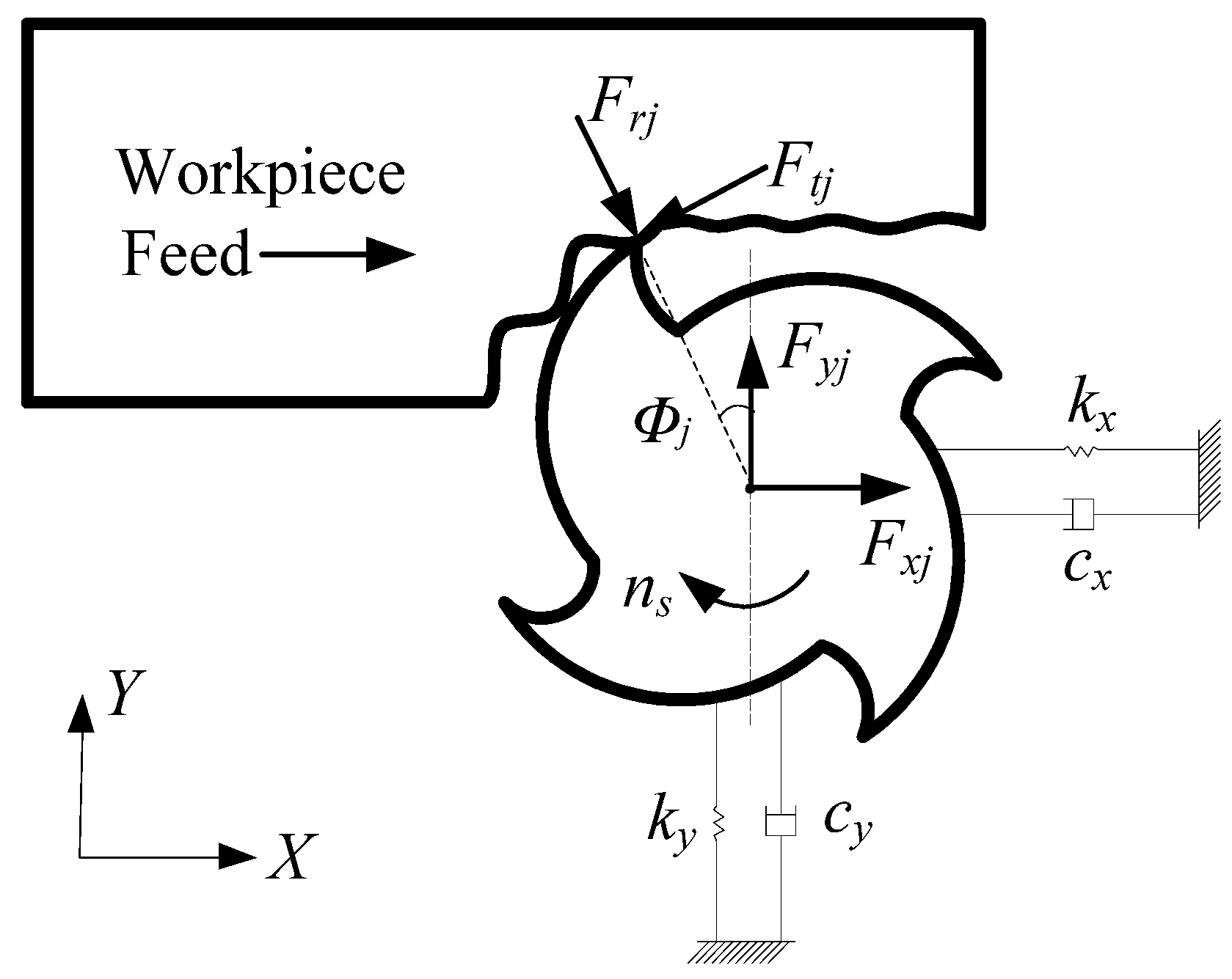
Figure 2.
Interference between flank face and machined surface of the workpiece.
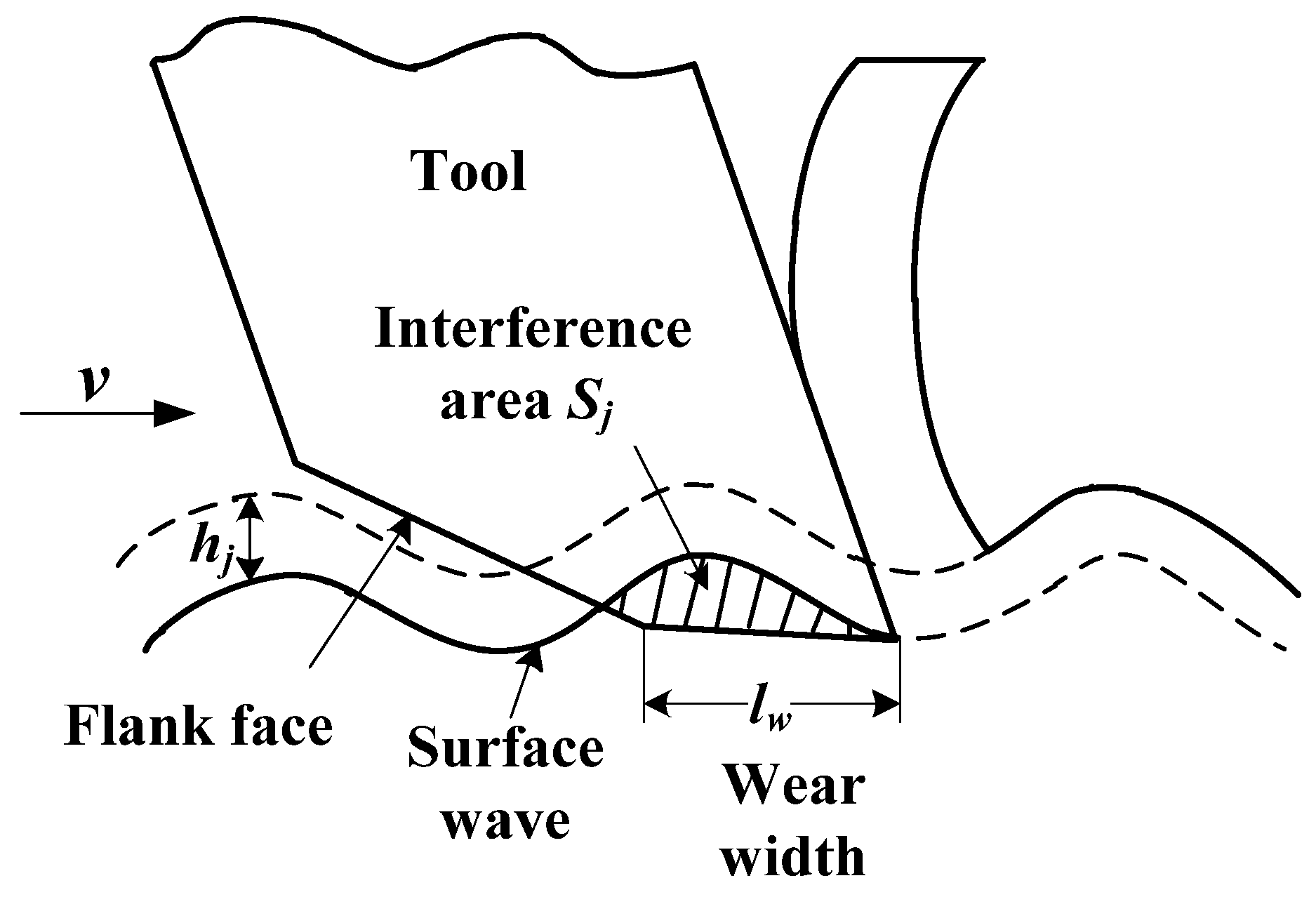
Figure 3.
Flowchart of optimizing variable pitch angles.

Figure 4.
FRF of the tool-spindle system; (a) under the industrial conditions; (b) under the laboratory conditions.
Figure 4.
FRF of the tool-spindle system; (a) under the industrial conditions; (b) under the laboratory conditions.
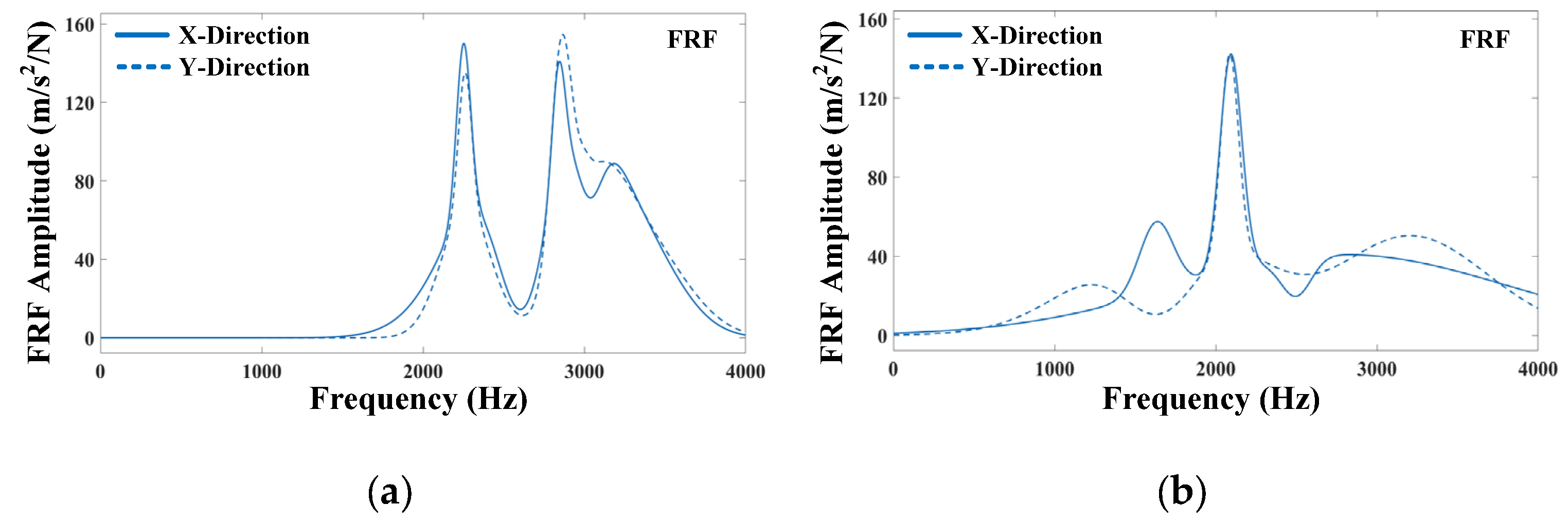
Figure 5.
Stability lobe diagrams under different tool design; (a) industrial cases; (b) laboratory cases.
Figure 5.
Stability lobe diagrams under different tool design; (a) industrial cases; (b) laboratory cases.
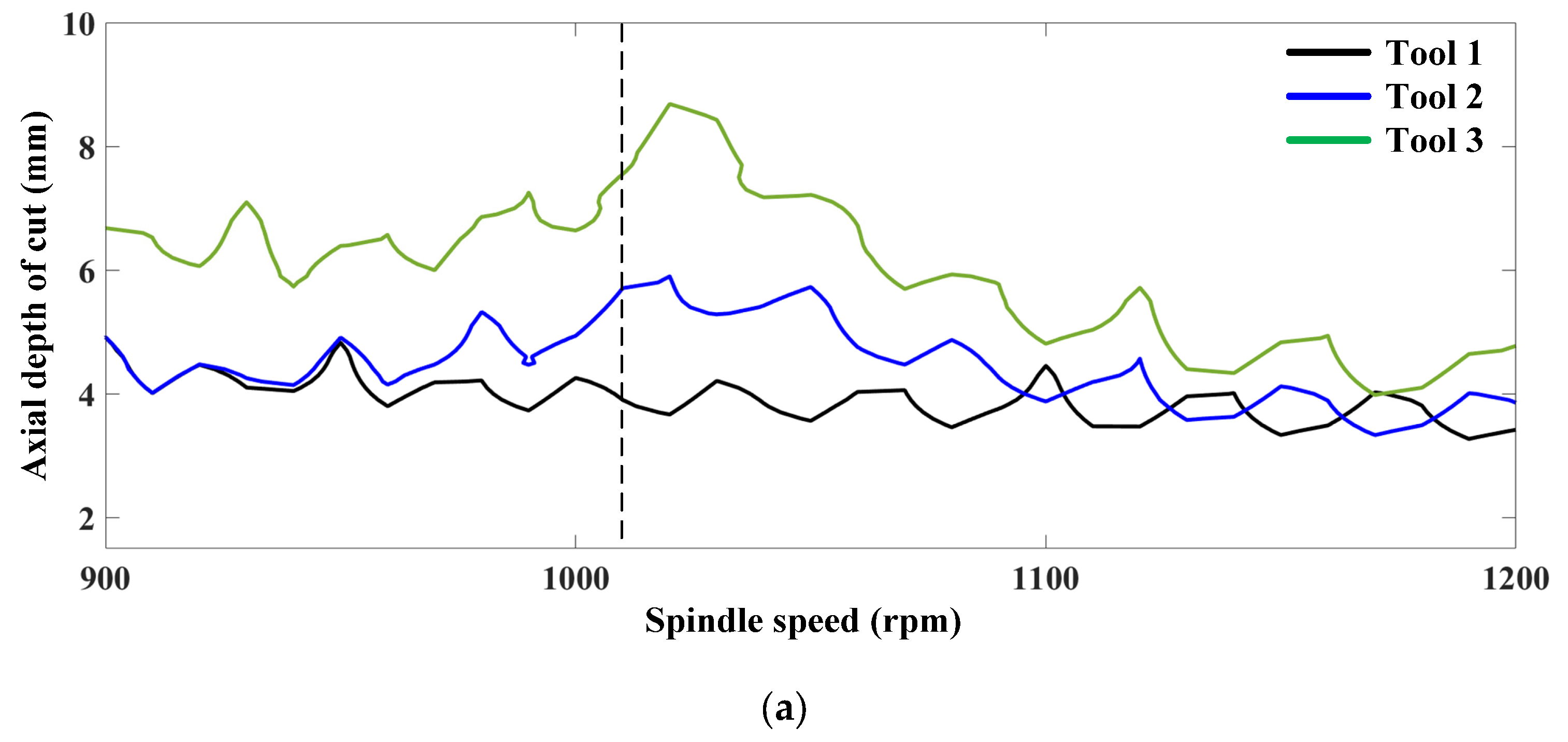

Figure 6.
Experimental setup of milling tests; (a,b) are milling experiments scenes under industrial condition; (c–e) is acceleration signals acquisition equipment; (f) is the geometry and microstructure of and the variable pitch tool (tool 2); (g) is the geometry and microstructure of and the anti-vibration tool (tool 3).


Figure 7.
Experimental results of industrial cases; (a–c) is measured chatter stability, acceleration signal and its FFT spectrum, and machined surface topography when variable pitch tool (tool 2) is used in the experiments; (d–f) is measured chatter stability, acceleration signal and its FFT spectrum, and machined surface topography when anti-vibration tool (tool 3) is used.

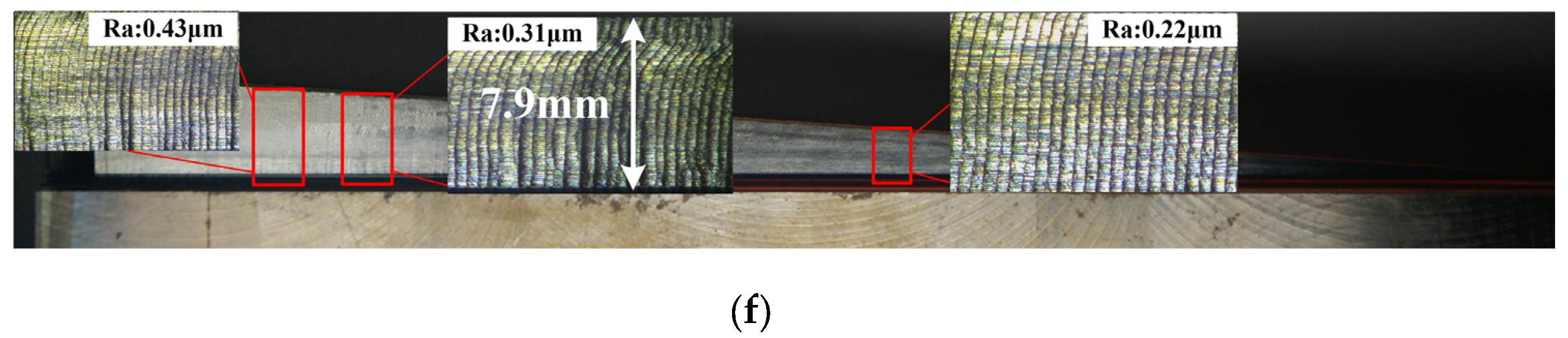
Figure 8.
Experimental results of laboratory cases; (a) stability diagrams and experiment points; (b) FFT spectrum of experiment point A; (c) FFT spectrum of experiment point B; (d) machined surface topography of experiment point A; (e) machined surface topography of experiment point B.
Figure 8.
Experimental results of laboratory cases; (a) stability diagrams and experiment points; (b) FFT spectrum of experiment point A; (c) FFT spectrum of experiment point B; (d) machined surface topography of experiment point A; (e) machined surface topography of experiment point B.


Table 1.
Geometrical parameters of designed tools.
| Tool 1 | Tool 2 | Tool 3 | |
|---|---|---|---|
| Tool material | Carbide end mill | ||
| Diameter | 12 mm | ||
| Tool length | 125 mm (30 mm edge length) | ||
| Number of flutes | 4 | ||
| Helix angle | 35° | ||
| Pitch angles | 90°-90°-90°-90° | 85°-95°-85°-95° | 85°-95°-85°-95° |
| Flank wear length | 0 μm | 0 μm | 60 μm |
| Clearance angle | 9° | 9° | 4° and 9° |
Publisher’s Note: MDPI stays neutral with regard to jurisdictional claims in published maps and institutional affiliations. |
© 2022 by the authors. Licensee MDPI, Basel, Switzerland. This article is an open access article distributed under the terms and conditions of the Creative Commons Attribution (CC BY) license (https://creativecommons.org/licenses/by/4.0/).
Share and Cite
MDPI and ACS Style
Li, M.; Zhao, W.; Li, L.; He, N.; Jamil, M. Chatter Suppression during Milling of Ti-6Al-4V Based on Variable Pitch Tool and Process Damping Effect. Machines 2022, 10, 222. https://doi.org/10.3390/machines10040222
AMA Style
Li M, Zhao W, Li L, He N, Jamil M. Chatter Suppression during Milling of Ti-6Al-4V Based on Variable Pitch Tool and Process Damping Effect. Machines. 2022; 10(4):222. https://doi.org/10.3390/machines10040222
Chicago/Turabian StyleLi, Mengyu, Wei Zhao, Liang Li, Ning He, and Muhammad Jamil. 2022. "Chatter Suppression during Milling of Ti-6Al-4V Based on Variable Pitch Tool and Process Damping Effect" Machines 10, no. 4: 222. https://doi.org/10.3390/machines10040222
Note that from the first issue of 2016, this journal uses article numbers instead of page numbers. See further details here.