Article

Design of a Spiral Double-Cutting Machine for an Automotive Bowden Cable Assembly Line

by
André F. G. Barbosa
1,
Raul D. S. G. Campilho
1,2,*,
Francisco J. G. Silva
1,2,
Isidro J. Sánchez-Arce
2,
Chander Prakash
3 and
Dharam Buddhi
4
1
Departamento de Engenharia Mecânica, Instituto Superior de Engenharia do Porto, Instituto Politécnico do Porto, R. Dr. António Bernardino de Almeida, 431, 4200-072 Porto, Portugal
2
INEGI-Pólo FEUP, Rua Dr. Roberto Frias, 400, 4200-465 Porto, Portugal
3
School of Mechanical Engineering, Lovely Professional University, Phagwara 144001, India
4
Division of Research & Innovation, Uttaranchal University, Dehradun 248007, India
*
Author to whom correspondence should be addressed.
Machines 2022, 10(9), 811; https://doi.org/10.3390/machines10090811
Submission received: 2 August 2022 / Revised: 11 September 2022 / Accepted: 14 September 2022 / Published: 15 September 2022
(This article belongs to the Special Issue Industrial Process Improvement by Automation and Robotics)

Abstract

:
The manufacture of automotive components requires innovative technologies and equipment. Due to the competitiveness in the sector, the implementation of automatic and robotic equipment has been vital in its development to produce the largest number of products in the shortest amount of time. Automation leads to a significant reduction in defects and enables mass production and standardization of the final product. This work was based on the need of an automotive components’ company to increase the rate of spiral cable cutting, used as protection for Bowden (control) cables. Currently, this component, used in automotive systems, is processed with simple cutting machines and cleaning machines. Based on the design science research (DSR) methodology, this work aims to develop a machine capable of performing the cutting and cleaning of two spiral cables simultaneously and automatically. The development of this machine was based on existing machines, and the biggest challenge was the implementation of a double-cutting system. The designed machine met the initial requirements, such as enabling the simultaneous cut of two spirals, being fully automatic, doubling the output over the current solution, and fully complying with the current legislation.

1. Introduction

Besides its economic importance, the automotive industry also contributes to technological innovation [1]. The need to remote control different functions within a vehicle is often satisfied using control cables. These functions vary from safety to comfort equipment. Applications of control cables are found in many fields of engineering such as robotics [2], and the automotive industry represents one of the most common and generalized applications [3]. Control cables, also known as Bowden cables, transmit linear motion and power by the relative displacement of cable or wire inside a spiral. Both of these components are flexible, which allows for several applications [4]. In addition, the efficiency of control cables is around 97% [5]. All these factors contribute to their large applicability. Control cables are composed of different components, apart from the inner cable and the spiral. Actually, depending on the application, the control cables may require special features such as grommets, low-friction coatings, anti-corrosive coatings, purpose-made cable ends [6], and supports or end connectors [7]. They are commonly employed to connect the control levers to latches such as those in engine and luggage compartments and door mechanisms. Some of their essential applications are for controlling the accelerator, clutch, and parking brakes through pedals and levers. In addition, they can be applied to comfort devices such as external mirrors and seats. Control cables should also have adequate strength to perform the required tasks and may be lubricated to reduce friction [8]. Since control cables are used to control critical components of vehicles, some standards regarding their materials, testing procedures, and production techniques have been published. For example, ISO standard 2408:2017 [9] specifies requirements for producing, testing, and marking steel cables, which are used in control cables. The inner cable, which is the one transferring motion and force, is made of braided steel wires forming a wire rope [4], with characteristics and types that are provided by Oberg et al. [10]. The cable sheath, also known as the cable housing, is made of a combination of materials, with emphasis on the steel spiral, which is arranged in a way that is strong in compression [4]. The spiral is often covered with plastic to protect it and its inners from the environment. In its interior, the spiral may have an antifriction coating or an inner tube to minimize the friction between the cable and spiral, which also prevents damage to the inner cable due to abrasion [11]. The spiral is a structural part of the control cable [4], hence, it is strong and difficult to cut. Furthermore, vehicle models even from the same manufacturer present different configurations of control cables, making it more difficult to automate the process. Consequently, the production and assembly of control cables often rely on several manual tasks, although some operations can be eased through jigs and fixtures [12].
The production of control cables was addressed as a case study by Moreira et al. [13]. The automated production of two different models of control cable was one of the requirements. The production of these cables was separated into three stages: preparation, injection, and assembly. The requirements were fulfilled by using integrated fully automated processes within a manufacturing cell [14,15]. Moreover, an integrated tooling system was implemented, allowing the production of the two desired models and leaving room for future expansions. The tooling had a computerized identification system, ensuring that the right tooling for the production run is installed in the cell. The concept was successfully implemented. Depending on the application, the inner cable may be subject to other operations prior to its assembly into the control cable set. An automated manufacturing cell was developed by Martins et al. [16], in which the inner cable was prepared for the zamak injection of its terminals and subsequently injected. In addition, the cable was cut-to-length and strength-tested. The manufacturing cell allowed for the production of three different models of control cable, each with different features. Some applications of control cables require lubrication, which is accomplished during the assembly process. In this regard, Ribeiro et al. [17] designed and implemented a system to lubricate control cables. The developed system allowed to maximize the use of the delivered grease regardless of the container type. Furthermore, a system of grease injectors, as well as the accompanying logistics, were developed and implemented. This also included an air detection system to minimize the mixture of grease-air, which negatively affects the lubricant properties. The proposed system led to efficient use of the grease supply, improved the lubrication of cables, and favored ergonomics and logistics on the factory floor. Subsequently, Vieira et al. [7] developed and implemented an automatic process to inject plastic ends into the spiral. The process consisted of the design of a production cell, where the plastic cap ends are injected. The cell was self-contained, allowing for its introduction within a production line of control cables. Although the work reported by Moreira et al. [13] is related to control cables, its focus was on the integration within a manufacturing cell, and, thus, the individual production steps were not fully described or addressed. Similarly, Martins et al. [16] described the overall process and the important steps, but the detail of the cutting process was omitted.
The cutting, deburring, and cleaning processes for the spiral, although mentioned in the literature, are not described for this particular component due to its specific nature. Nevertheless, the spiral is a metallic component, and, hence, cutting processes suitable for metal pipes and stock are applicable [11]. For example, Li et al. [18] performed a review of the state-of-the-art cutting processes and the effect of tool geometry on surface finish, wear, and heating. Nonetheless, the large number of variables involved in this type of process indicates the need for extensive testing for the process of interest due to operational concerns [19]. For example, the plastic coating on the spirals may require special attention during the cutting process to prevent heat damage [20] or catching fire. This combination of materials, metal, and plastic is suitable to be cut using mechanical or abrasive means [21], providing that cooling is used. In this regard, cooling has to be environmentally and product-friendly. Cooling and lubricating during machining and cutting have different alternatives, which also depend on the type of material being processed. Nevertheless, a current trend is to minimize the amount of coolant used by improving the tool geometry and cutting parameters through simulations and experimentation, as reviewed by Mohamed Akeel et al. [22]. In addition, the available tests in the literature mostly pertain to flat substrates, whilst hollow substrates may present a challenge. Spirals are hollow and relatively thin, so cutting may be difficult, since thin shapes may deform due to cutting forces [18,23,24], especially for shear cutting (with guillotines), which would not be applicable for spiral processing. Resulting from a survey of industrial equipment, the most used method to cut this component is abrasive disk cutting, which typically presents good efficiency and speed that, together with its reduced cost, make this one of the most used methods in the cable industry. Abrasive grains of aluminum oxide, silicon carbide, or zirconium are recommended [25]. However, due to the friction that is generated between the disk and the part, the heat produced in this zone grows exponentially, rapidly expanding to the entire system. Therefore, it is necessary to study this situation in advance, in order to avoid damaging the system. Diamond disk cutting can be an alternative that greatly reduces pollution generation and improve performance with a respective increase in service life, but with a higher cost [26]. Other cutting techniques such as abrasive waterjet [27] or laser cutting [28] have been explored for metallic and composite materials with success, although the parameters must be optimized for each application. Abrasive waterjet cutting in particular involves a good edge sharpness and low initial investment and avoids the heat-affected zone [29], but for spiral cutting can promote the water ingress to the spiral. Laser cutting leads to reduced contamination of the workpiece, good dimensional accuracy, and negligible warping [30]. However, heat generation can cause a problem for plastic components. Plasma cutting seems less suitable, since it is less precise and uses more energy than laser cutting, although it cuts bigger thicknesses [31]. Despite the several processes available to perform the task, their applicability is case-dependent, being necessary to model and experiment with a given material and equipment to maximize performance and the product’s quality.
As previously described, amongst the several components of control cables, automated production of spirals ready for assembly has not been studied. This work was based on the need of an automotive components’ company to increase the rate of spiral cable cutting, used as protection for Bowden (control) cables. Currently, this component, used in automotive systems, is processed in simple cutting machines and cleaning machines. This work aims to develop a machine capable of performing cutting and cleaning of two spiral cables simultaneously and automatically. The development of this machine was based on existing machines, and the biggest challenge was the implementation of a double-cutting system.

2. Methods

2.1. Selected Methodology

The automatic machine developed in this work for spiral double-cutting followed the design science research (DSR) methodology. This approach is particularly suited for the design and improvement of existing processes, as in the current work, and it involves the detailed study of the existing processes and proposal of new solutions arising from the inputs of different participants in the process, leading to an improvement process that can be used in different disciplines [3]. The DSR methodology is step forward compared to traditional design, in which the interested parties (companies) define the objectives and requirements in a short-term perspective, limited by the available knowledge and productions resources. Some limitations can also be pointed out, such as the requirement for a detailed analysis of the initial process, possible need for multiple iterations, and added time to the project [32].
The DSR methodology can be described by six stages [33]:
  • 1—Identification of the problem—Analysis of the current machine, description of limitations and improvement points;
  • 2—Objective definition—Establishment of the objectives and requirements to attain the desired result;
  • 3—Design and development—Choice of the news concepts to implement, based on the requirements;
  • 4—Solution demonstration—Implementation of the concepts defined in the previous stage;
  • 5—Solution evaluation—Performance analysis of the solution and verification against the initial objectives/requirements;
  • 6—Conclusions—Comparison between the initial and new solutions.
In view of this procedure, Section 2.2 (control cable and initial machine) and Section 2.3 (problem characterization) relate to stage 1 (identification of the problem). Stage 2 (objective definition is accomplished in Section 2.4 (objectives and requirements). The pre-design Section 3.1 of Section 3 partially fulfills stage 3 (design and development), by choosing the cutting concept to implement. It should be emphasized that a similar procedure was followed for the other machine constituents, although in this paper only the main issue to address was explicitly shown. Stages 4 (solution demonstration) and 5 (solution evaluation) are diluted in Section 3.2 (final solution) and Section 3.3 (design process). In these stages, and due to the limitation that the physical construction of the new machine was not possible to accomplish before the idealized solution was made ready for the company, implementation and evaluation of the concepts were carried out virtually using software by the relevant design team and company personnel. Finally, stage 6 (conclusions) is the core of Section 4 (discussion and conclusions), where the initial and new machines are compared, and the improvements are assessed.

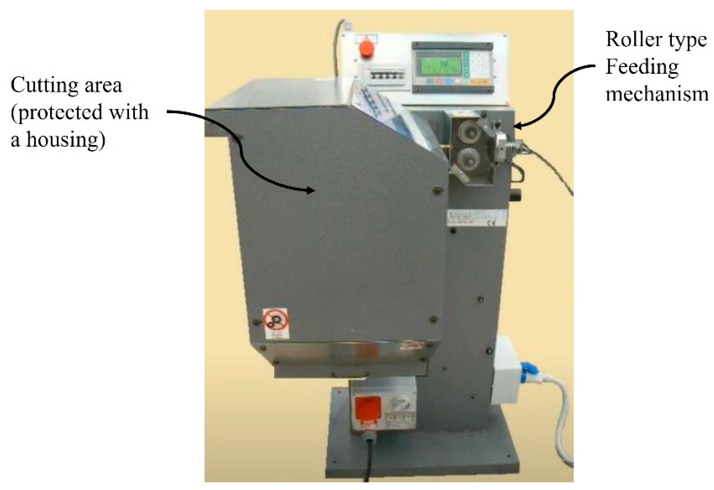
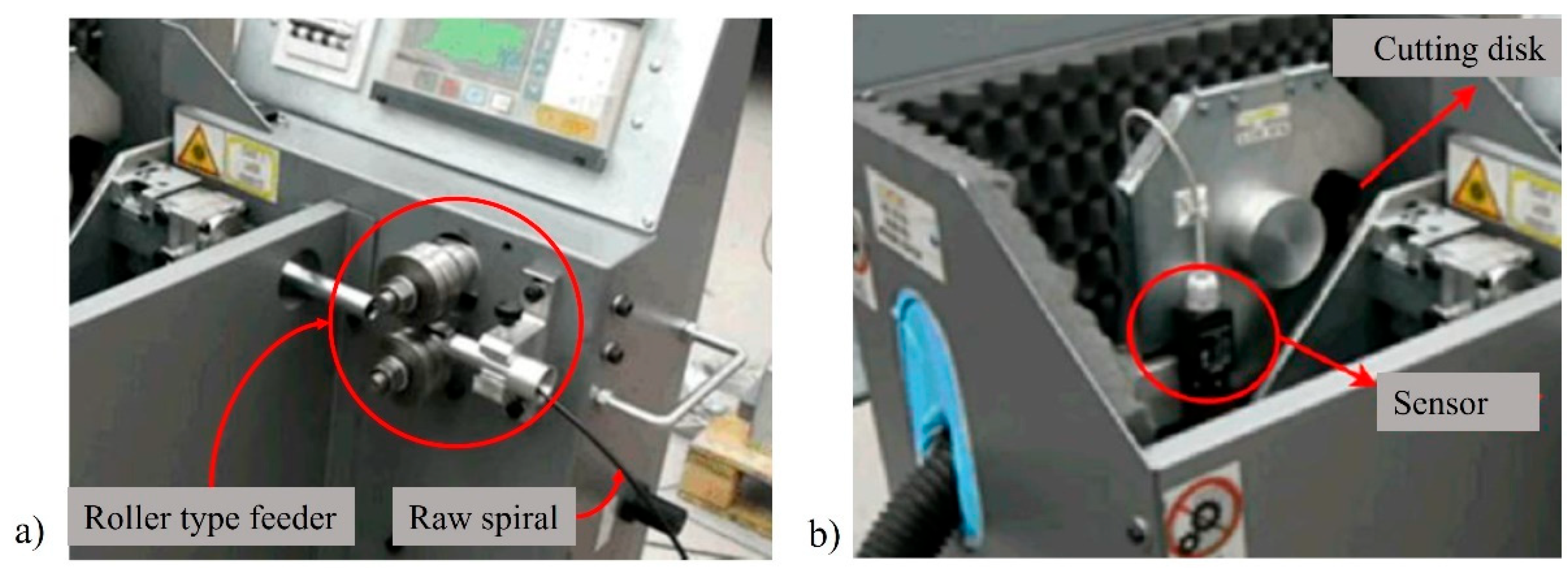
2.2. Control Cable and Initial Machine

The automotive components’ company produces control cables, many of which are for automotive use. Figure 1 shows an example of control cable. As mentioned before, control cables are composed of different parts depending on the application, with the inner cable and the spiral as their most important constituents.
The main materials of the control cable are stainless steel for the inner cable, Zamak 5 alloy (zinc die casting alloy) for the cable terminals, polymers for the outer accessories (including an elastomer for the grommet), and the spiral materials, which are particularly relevant for this work, since these will be subjected to the cutting operation.
  • Spiral body-spring steel (medium-carbon, with 0.5–1% C, and main alloy elements 0.15–0.35% Si, 0.6–0.9% Mn, 0.4% Cr, 0.1% Mo, and 0.4% Ni), providing a high yield limit to assure flexibility in the elastic regime. The spiral was heat treated to provide an elastic limit of 650 MPa and tensile strength of 900 MPa.
  • Outer coating-used for spiral outer protection and composed of polypropylene applied in the spiral body by wire-coating extrusion, after the spiral reaches room temperature. This polymer is a thermoplastic obtained by chain-growth polymerization from the monomer propylene, with good heat and chemical resistance. The Young’s modulus between 1.3 and 1.8 GPa provides the required flexibility without breaking.
  • Inner tube-inserted inside the spiral to guide the inner cable during operation with low resistance to motion, made of PA66 (polyamide 66) to provide excellent abrasion resistance and low frictional properties, while retaining acceptable strength and toughness and being resistant to oils, greases, and fuels. The approximate Young’s modulus of 3.5 GPa ensures the desired flexibility for this application.
An example of the current machinery is shown in Figure 2. These machines use an abrasive disk to cut the spirals, which are fed by a set of rollers. The cut is performed with a silicon carbide (SiC) disk cooled by using compressed air.
The current cutting mechanism cuts a spiral at a time. Therefore, this mechanism was used as a starting point for all the improvements. The cutting mechanism possesses a motorized roller type feeder (Figure 3a). In this type of feeder, the raw spiral is compressed between the rollers with enough pressure that the friction between them pushes the spiral into the machine without deforming it. The feeder system pushes the spiral into the cutting area where it is cut using an automatically actuated abrasive disk (Figure 3b). The cutting motion is driven by a servomotor (Figure 4), whilst the cutting disk’s wear is compensated by means of sensors, as shown in Figure 3b. The cutting disk is cooled by compressed air directed to it through a nozzle system (Figure 4). Although abrasive disks efficiently cut this type of material, subsequent preparation and cleaning are required due to the burrs left on the surface.
Currently, metal chips and dust are projected during the process, and most of them lie on the floor and machine, despite all the attempts to mitigate this problem. Once the spirals are cut, they are transported to another station where the burrs are removed, and the cuts cleaned for further operations down the line. However, the transport between the cutting station to the cleaning station is done by hand. On the other hand, the cleaning station, as shown in Figure 5, receives the spirals through two conveyor belts, which have an adjustable span to allow for different spiral lengths. The conveyor belt system moves the spirals to an alignment device, ensuring that all the spirals are aligned with the machine. Then, each spiral passes through five stations: (1) reaming, (2) grinding, (3) flaring, (4) heating, and (5) blowing. This process results in cable spirals with equal length and up to standard. Regarding the cleaning station, the conveyor belts have magnetic attachments, which allow for holding the spirals, though they also attract metallic debris. The conveyor belt drive is powered by a servomotor, allowing the precise positioning of each spiral through all the stations.
In summary, the weakest point of the current cutting method is the quality of the final cuts, which require further processes to remove, and associated amount of dust and metallic debris that the process leaves on the machine and spirals. Then, the need for manual transfer between stations limits the production rates. In consequence, there is room for improvement using the current machine as a starting point, which would also increase the productivity of the machinery.

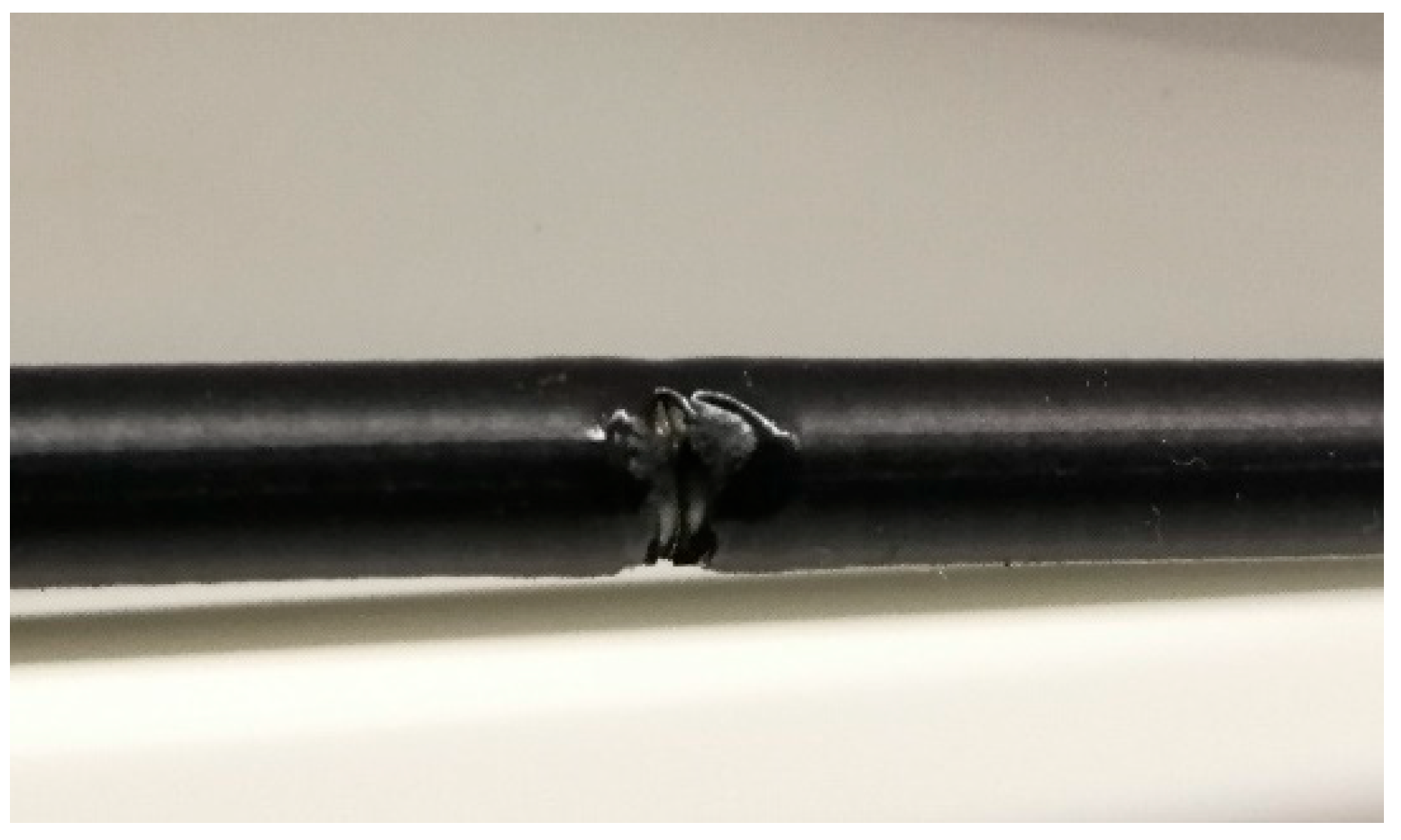
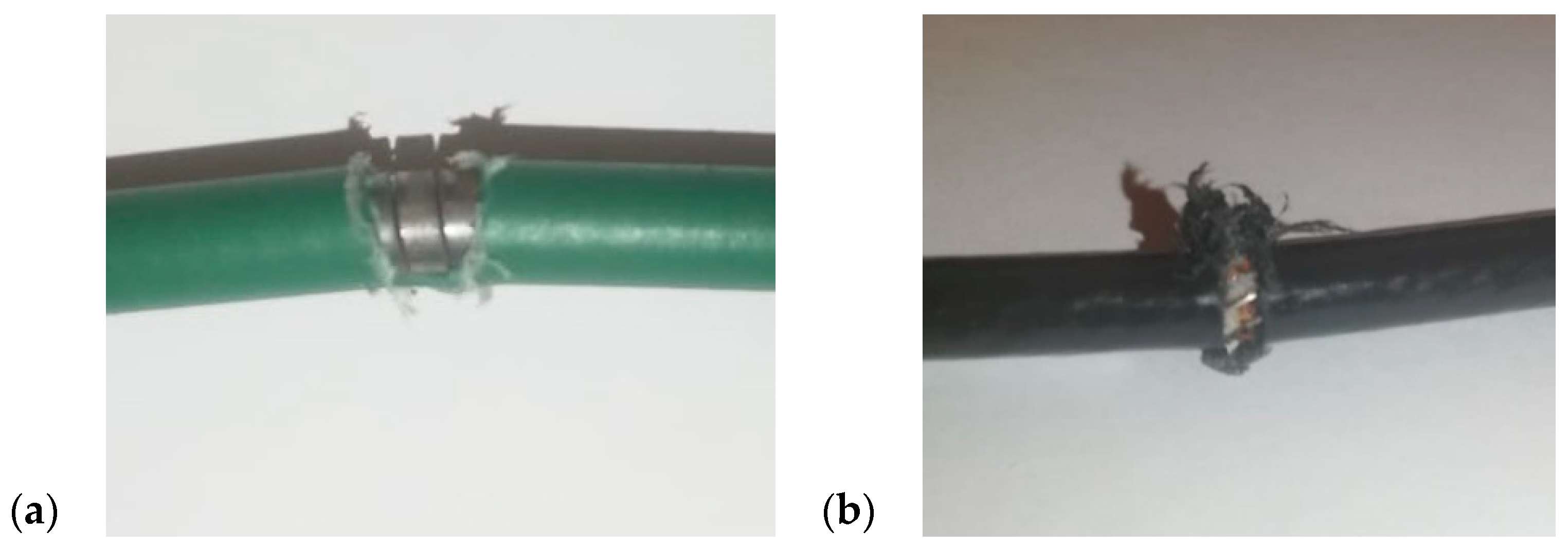
2.3. Problem Characterization

Although the company already has infrastructures to produce the cables, there is the need to optimize the process because, in the current form, the machinery cuts one cable spiral at the time. Once the cable spirals are cut, they are transported to another station where their ends are deburred and cleaned (post-processed). However, the transport and post-processing are still manual tasks. Using single-spiral-cutting machines, given the number of manual tasks, results in low production rates. Although the current process is viable, the results of the cutting process are far from repeatable, affecting the quality. Therefore, it is necessary to improve the process and ensure the final quality of the spirals. In consequence, it is proposed to develop and implement the processes and machinery to allow cutting and post-processing of two spirals simultaneously, and then arrange all of them into a manufacturing cell following safety and ergonomic standards.

2.4. Objectives and Requirements

The main objective is to develop a cutting system able to cut, clean, and deburr two spirals at a time. In addition, the idealized solution should integrate with the current production lines at a minimum cost, while reducing the allocated human resources, assuring the required quality level by the clients, and increasing the production output. As a result of this work, a project should be proposed that can be manufactured, assembled, and used in an industrial environment with significant benefit over the current manually operated single-cutting machine. The raw spirals are supplied wound on spools, and, thus, the system should account for this feature. Then, the raw spirals should be automatically fed into the cutting system. On the other hand, the variety of models produced by the company leads to different cable lengths, varying from 200 mm and 600 mm, so the proposed system should take this into account, expecting an automatic or semi-automatic measurement system. The cutting would proceed in batches of a certain length. Therefore, the length would be adjusted on every batch to be produced. Finally, the system should deburr and clean the inside and outside diameters of the cut spirals as automatically as possible. In addition, the proposed system should take advantage of current equipment and facilities, and the respective implementation should cause minimum disturbances to the production and be affordable.
This project must always consider the fulfilment of the initially imposed requirements. Only compliance with these will guarantee the quality of the products, the necessary production rate, and the proper functioning of the industrial environment in which it will be inserted. In summary, the system’s requirements are as follows.
  • Automatic spiral feeding system. The raw spiral is wound on a spool; hence being part of the process.
  • Cut two spirals simultaneously.
  • Automatic or semi-automatic (at minimum) cut to length system. The length ranges from 200 mm to 600 mm. The machine should enable to set the length first and then cut all the batches to length.
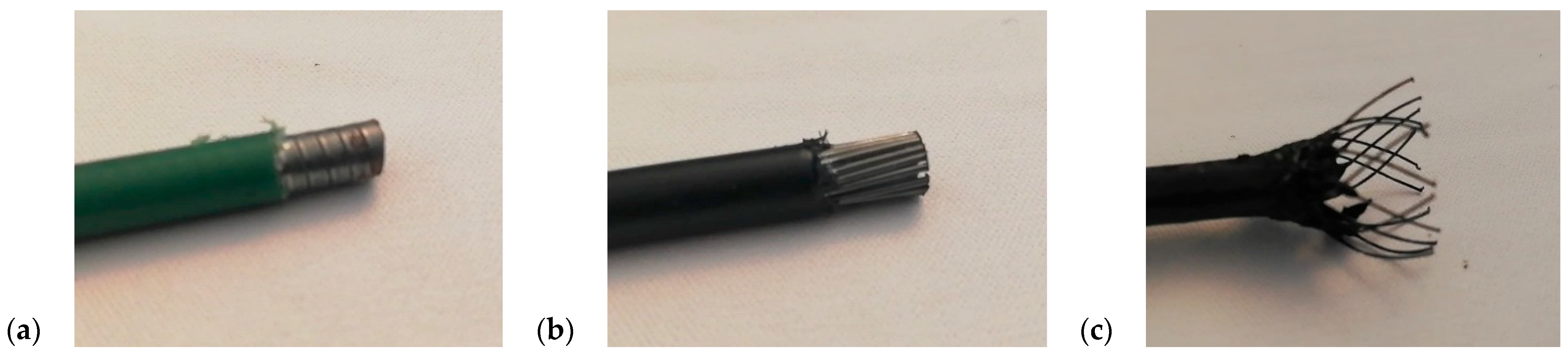
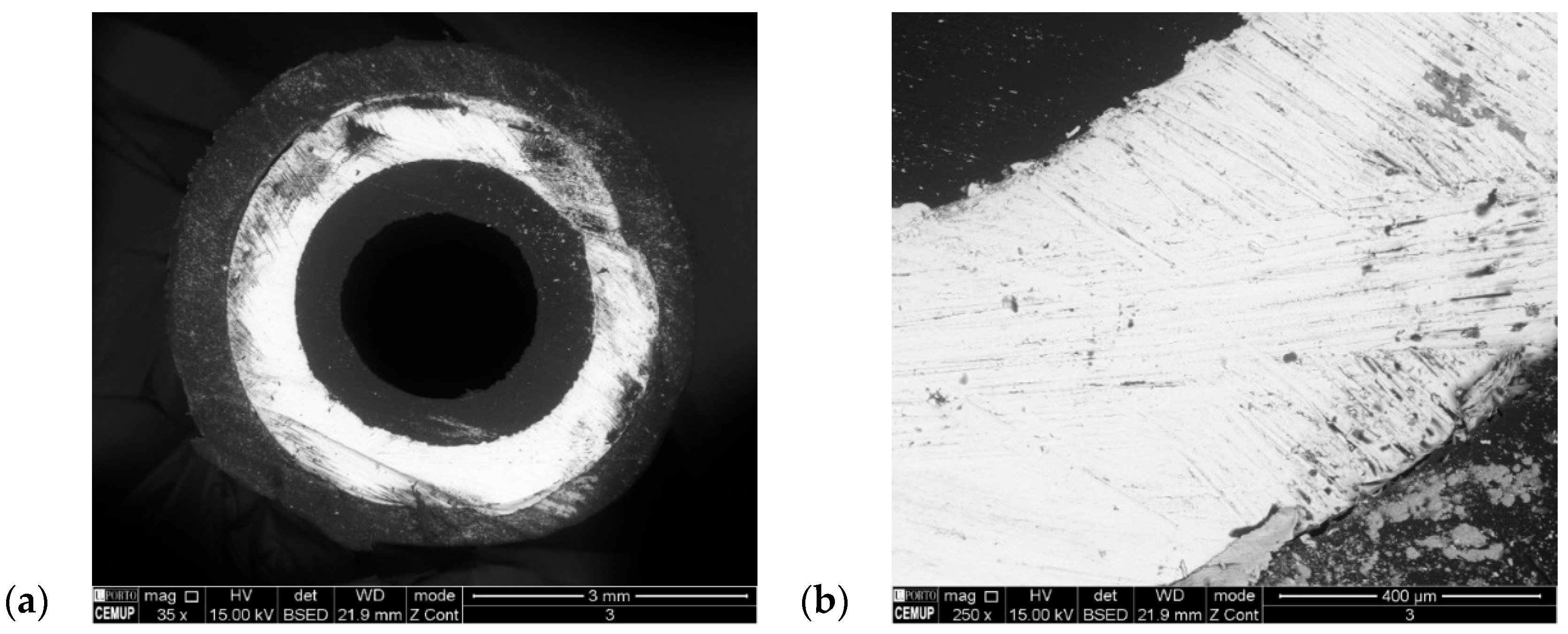
  • Cutting quality must be guaranteed to facilitate the cleaning process and guarantee the quality of the final product. Thus, the machine must be able to make a clean cut both on the spiral and on the components attached to it, such as the casing or the inner tube.
  • Clean and deburr the spirals. The sleeve should come out of the machine ready for use, i.e., it must be ready for a steel cable to be passed inside it, so that it can receive terminals if necessary. For this, it must not have burrs, obstructions in the hole, or damage to the casing.
  • Provide a cost-effective solution, which is highly relevant in the competitive automotive components industry, leading to a reduced return-on-investment for currently operating machines.

3. Results

3.1. Pre-Design

The pre-design stage of the current project was carried out to serve as the basis for the project. This study involved all phases of brainstorming, testing, and analyzing of the possible problems and goals to be achieved. The implementation of a double-cutting system creates additional design difficulties that do not exist in a single-cutting system, such as the cooling problem. Thus, different hypotheses emerged to replace the cutting system. After verifying the presented hypotheses, the solutions that would respond to the imposed problems were selected. Due to the experience of using this type of equipment, some changes were also suggested to avoid the additional problems found in the existing machines in the company. The different hypotheses were cutting with an abrasive disk (current solution), laser cutting, waterjet cutting, and diamond disk cutting. Shear cutting was ruled out from the beginning due to the involved deformations arising from the hollow spiral geometry, which prevents the correct functionality of the control cable. The different hypotheses were tested, so that it was possible to choose the most viable one. As for cooling, the possibilities of projecting gases such as carbon dioxide or nitrogen as well as cooling with water and air were considered. The tests carried out for the different cutting techniques considered the use of three types of spirals (Figure 6): laminated spiral without inner tube, push-pull spiral, and braided spiral.

3.1.1. Laser Cutting

The first solution to replace the current cutting system was laser cutting. Spiral samples were sent to a specialized company in laser cutting (MACSA), which performed tests with an F9100 beam: a 100 W beam with ultra-high speed (UHS), as recommended by the company for the specimen dimensions and materials involved. Sample results for the laminated spiral are shown in Figure 7. Good results were not obtained, as the required cutting time is slightly higher than the current abrasive disk cutting, and the overall cut quality is poor. Actually, although the metal component can be cut with a minor burr, the plastic coating that protects the spiral tends to melt and leaves a poor finish. As shown in the figure, the laser beam ended up damaging the coating even before coming into contact with the spiral cable. Different processing conditions, such as higher power combined with shorter process time, were tested within the limits of current technology and application to a production line, but it was not possible to prevent melting of the plastic coating, which affects the subsequent process operations. Thus, the possibility of laser cutting was ruled out, due to non-compliance with quality requirements.

3.1.2. Waterjet Cutting

The second tested solution consisted of waterjet cutting. It was necessary to build a structure that would allow the fixation of the spiral during the cuts. The test setup consisted of a steel fixation jig to hold the wire and hinder spiral deformations during the operation. The tests were carried out at the company JACQUET Portugal, with a pressure of 4000 bar, considering the possibility of using abrasive particles together with the water to facilitate cutting, i.e., tests with and without abrasive were considered. It was concluded that waterjet cutting without abrasive cuts the plastic coating but is not capable of cutting the steel spiral. Figure 8 shows representative examples for a laminated spiral without inner tube (a) and a braided spiral (b), with emphasis on the degradation state of the coating with little to no effect on the metal part.
On the other hand, the abrasive waterjet cuts the entire cable without difficulty, but, as observed for laser cutting, it results in significant coating degradation. Moreover, in the case of spirals equipped with an internal tube, the cut region becomes clogged with plastic residues, which affect the assembly of the inner cable. Examples are given in Figure 9: a push-pull spiral (a) and a braided spiral (b).
At a later stage, it was also possible to observe that, with time, oxidation of the steel spiral occurs due to water ingress to the interior of the spiral, where it remains and ends up oxidizing the material. It can, thus, be concluded that this process requires the implementation of a system that guarantees the drying of the entire spiral. Thus, by analyzing the obtained results, the possibility of adopting a waterjet cutting system was discarded, since it would not be able to meet the necessary requirements.

3.1.3. Diamond Disk Cutting

The possibility of replacing the abrasive disk with a diamond disk was also tested. For this, a STRUERS Minitom cutting machine was used. Two types of spirals were analyzed: laminated spiral and braided spiral. For the braided spiral, diamond disk-cut samples were collected. For the laminated spiral, samples were collected and cut with diamond and abrasive disks, to compare the results. The samples were sent to a specialized laboratory, where a microscopic scanning analysis was performed. Results of the braided spiral with diamond disk cut are shown in Figure 10 (sample 1). For the laminated spirals, two samples were collected, namely with a diamond disk cut (Figure 11; sample 2) and an abrasive disk cut (Figure 12; sample 3).
Analysis of the results shows that the cut surfaces contain several defects when analyzed microscopically. Sample 1 showed some signs of steel oxidation, due to exposure to air, which is a natural phenomenon in this type of material. In sample 2, there are some defects in the cut of the coating and inner tube. In both samples, the cut surface is scratched due to the action of the rotating disk. In sample 3, however, this defect is more noticeable due to the high roughness of the abrasive disk compared to the diamond disk. Nonetheless, the defects pointed out do not prevent the correct use of the spirals, contrarily to what happened in the laser and waterjet cutting tests. Thus, the implementation of a diamond disk could be a possible solution. However, the diamond disk does not prove to constitute a reason for the reduction in defects, by providing a similar result to the abrasive disk. Moreover, the existing cutting system (abrasive disk) is already proven and put into practice, while the diamond disk solution would need further testing in an industrial environment. On the other hand, it is also necessary to consider the cost of the diamond disk, which is much higher than that of the abrasive disk. The diamond disk also requires specific cutting speeds to avoid rupture, which would require changes in the existing cutting concept. It was, then, assumed that the abrasive disk is sufficient for the work to be carried out. However, it is important to keep the disk at a low enough temperature, so as not to be affected by thermal fatigue.

3.1.4. Abrasive Disk Cutting with Cooling

The hypothesis of keeping the currently used cutting method gathers significant know-how from the company. This method does not require additional testing, as it is validated in real operating conditions. However, it is necessary to consider the heating issue, which is aggravated in a double-cutting system. Cutting disk cooling is, as mentioned, essential due to the heat generated in the cutting disk housing. The temperature is higher compared to a single-spiral-cutting system, and it affects both the surrounding atmosphere and the disk itself. Therefore, it is essential to include a cooling system capable of removing the hot air generated in the cutting area and cooling the cutting disk.

3.1.5. Selection of the Best Idea

The best idea for the cutting process was assessed by the selection table methodology (or Ashby methodology) [34]. Initially, it is necessary to establish the criteria by which each idea should be scored for a comparative evaluation between ideas. After a detailed analysis of machine/production line functionality and required features for the cut spirals, the following criteria were selected.
  • Cutting quality: includes coating degradation, cut section geometry, and possibility of debris accumulated in the spiral, leading to subsequent cleaning operations and increased cost/time.
  • Cutting time: shorter cutting times increase productivity.
  • Process know-how: from the company that requested this machine, to facilitate implementation and operation of the new idea in the company’s production lines.
  • Cost: cost to fabricate and implement the cutting system.
  • Heat generation: affects the cut quality and requires proper dissipation systems in the machine.
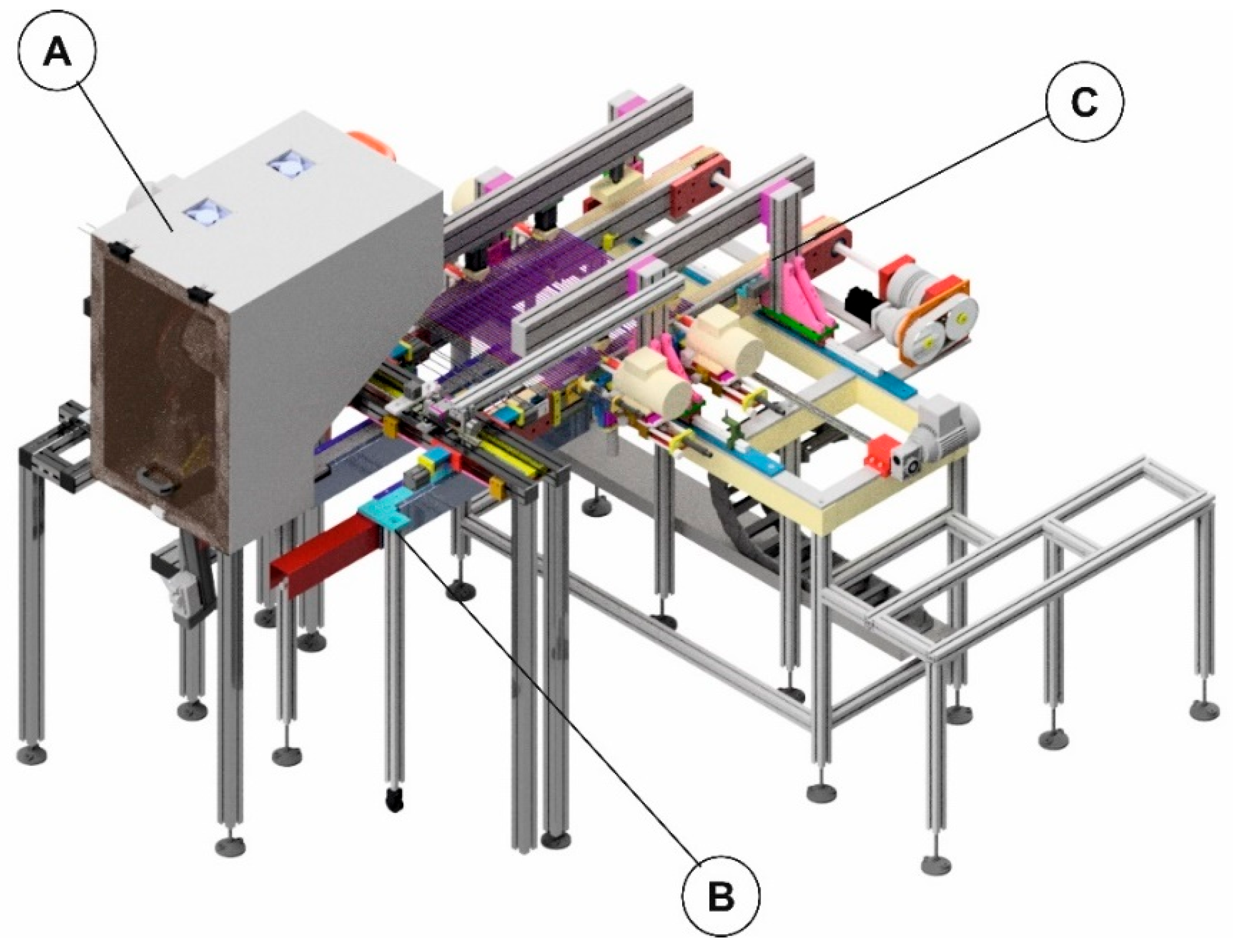
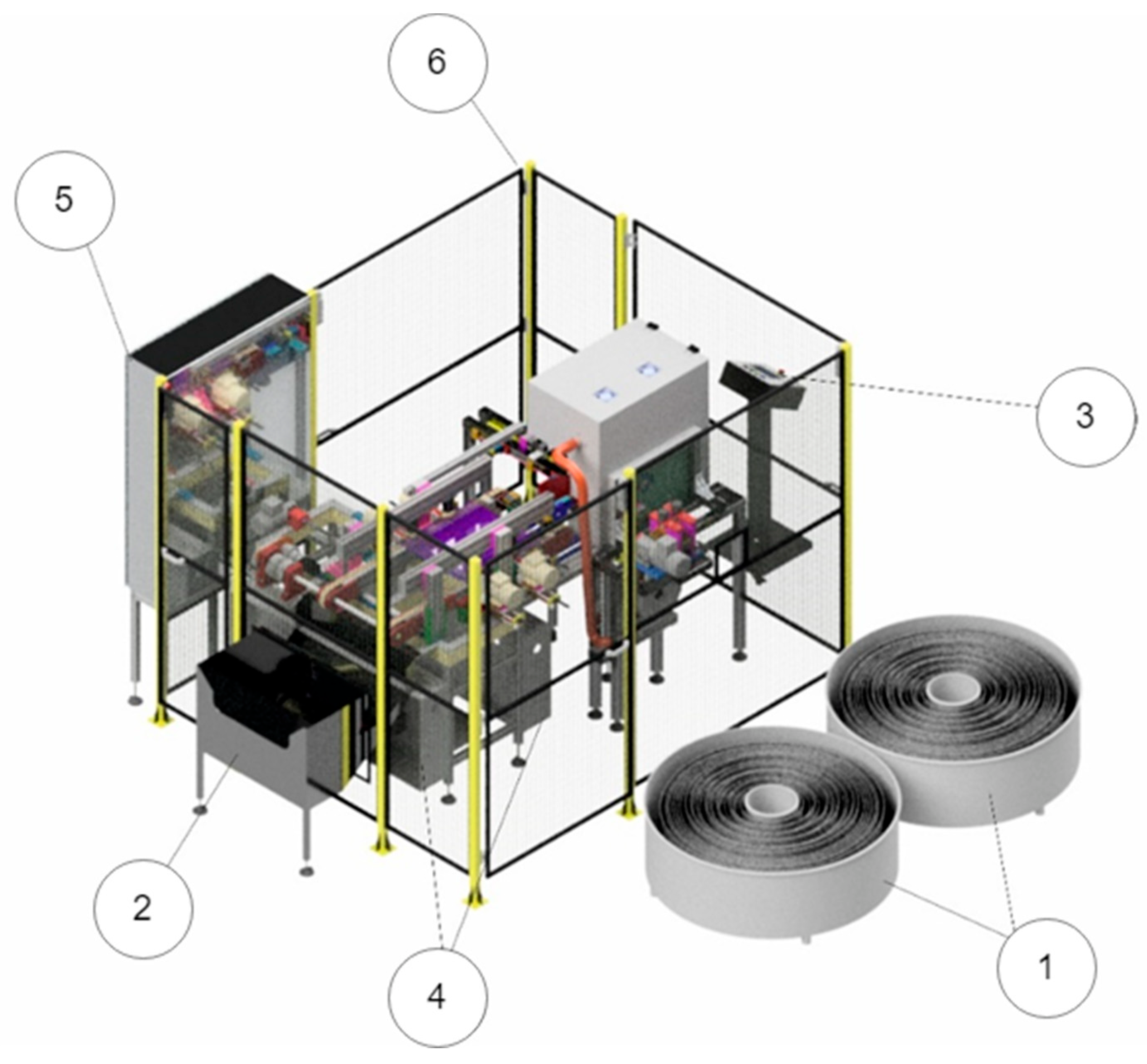
Next, the relative importance of each criterion (wi) should be selected. By building a selection table and comparatively ranking each pair of ideas, following the procedure of Nunes et al. [35] and considering criterion 1 as the comparison standard, the following wi were attained (satisfying Σwi = 1): w1 = 0.33, w2 = 0.18, w3 = 0.10, w4 = 0.15, and w5 = 0.24. The classification of each idea (Vi) is then calculated. With this purpose, a qualitative scale between 1 and 5 was established, in which 1 is the “least favorable” and 5 is the “most favorable” classification. In this process, a comparative evaluation between all ideas is performed to provide a relative hierarchy and reduce uncertainty. The weighted classification of each idea (βi) is given by βi = Vi/MVi (×100), in which MVi is the highest Vi between all ideas. The idea classification in each criterion (Ωi = wi × bi) is then calculated to produce the final classification of each idea (γi = Σ(wi × bi)), leading to the choice of the highest ranked idea. Table 1 presents the selection matrix for the choice of spiral cutting process, in which the selected criteria were sorted from biggest to smallest wi in columns, and Vi were defined in view of the aforementioned discussions for each candidate cutting process. By applying this methodology, the current process (abrasive disk cutting with cooling) was selected and is considered in the machine design that follows.
However, prior to design, for cooling during the abrasive disk cutting process, several hypotheses were considered: with water projection, with compressed air projection, with projection of inert gases, and with fans included in the system. The use of water for disk cooling was a hypothesis discarded early on, due to oxidation of the steel spiral, which is accelerated by the ingress of water, and dirtiness, due to debris coming from the cut in contact with water. The projection of compressed air, as analyzed in the initial project, would become economically unfeasible. For the same reason, the projection of inert gases such as carbon dioxide or nitrogen can also be ruled out. The possibility of inserting hot air exhaust fans present in the cutting disk housing was then considered. With this approach, the temperature in the atmosphere surrounding the working zone of the disk could be reduced. However, the cutting disk would reach very high temperatures, so it is imperative to include another system responsible for its cooling. It was then decided to install a centrifugal fan in the system capable of delivering air to the disk surface without using compressed air. Thus, the solution found for cooling the cutting system involves the inclusion of hot air exhaust fans and a fan with cold air projection directly onto the disk.

3.2. Final Solution

The final machine was developed to comply with the mentioned objectives and requirements, and with the guidelines defined in the pre-design stage. After selecting the cutting and cooling systems, it was necessary to build the machine. The machine can be divided into three main systems, as shown in Figure 13: A-cutting mechanism, B-manipulator, and C-spiral preparation and cleaning system.
These systems interact with each other promoting the desired processing of the spiral. Figure 14 shows the global representation of the machine, including the three main systems and the components that, although not part of the spiral processing, are indispensable in the operation of the machine: 1-spiral coil containers, 2-spiral cut output container, 3-control panel, 4-valve boxes, 5-electrical panel, and 6-safety barrier.
The developed machine makes it possible to feed the spirals from the spiral containers (Figure 14-1). The spirals are removed from the spool and enter the machine through the cutting mechanism (Figure 13-A), where they will be positioned and cut to the desired length (between 200 and 600 mm). The manipulator (Figure 13-B) transports the spirals to the preparation and cleaning system (Figure 13-C). In this system, the necessary processing is carried out at various stations to give the spirals the necessary finish. When this procedure is finished, the spirals fall to an outlet container (Figure 14-2). The machine is operated by the control panel (Figure 14-3), which interacts with the components of the valve boxes (Figure 14-4) and the electrical panel (Figure 14-5), allowing for the driving of the automatic systems of the machine. The safety barrier (Figure 14-6) is a safety component that surrounds all the machine and prevents people from approaching the most dangerous components. To facilitate the analysis of the developed project, different colors were assigned to the components used to promote their distinction. A reference was also given to the parts developed to facilitate a simpler organization of the project. No reference was assigned to standard components, as they already contain the supplier’s reference.

3.3. Design Process

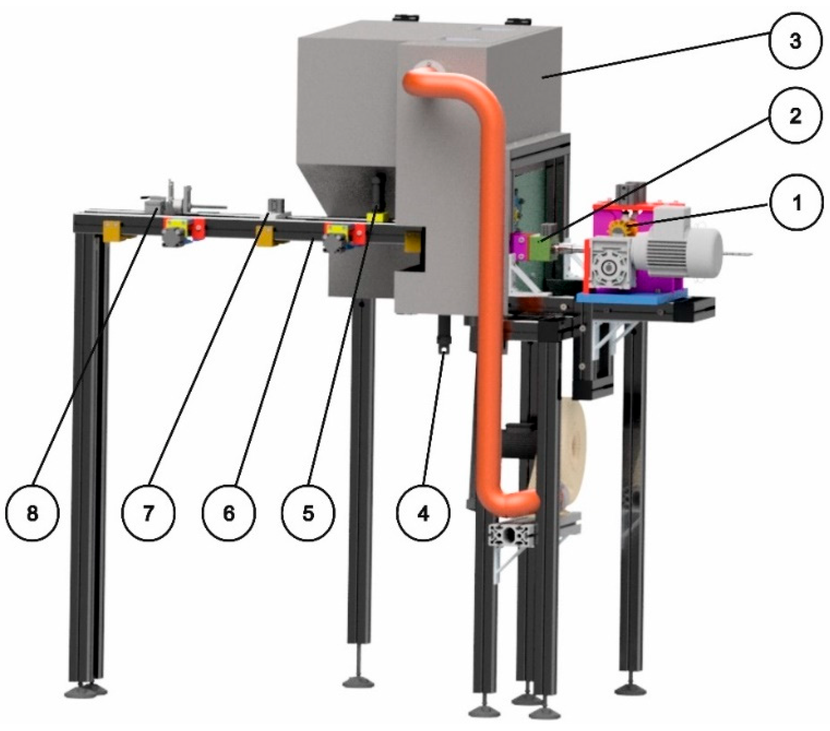
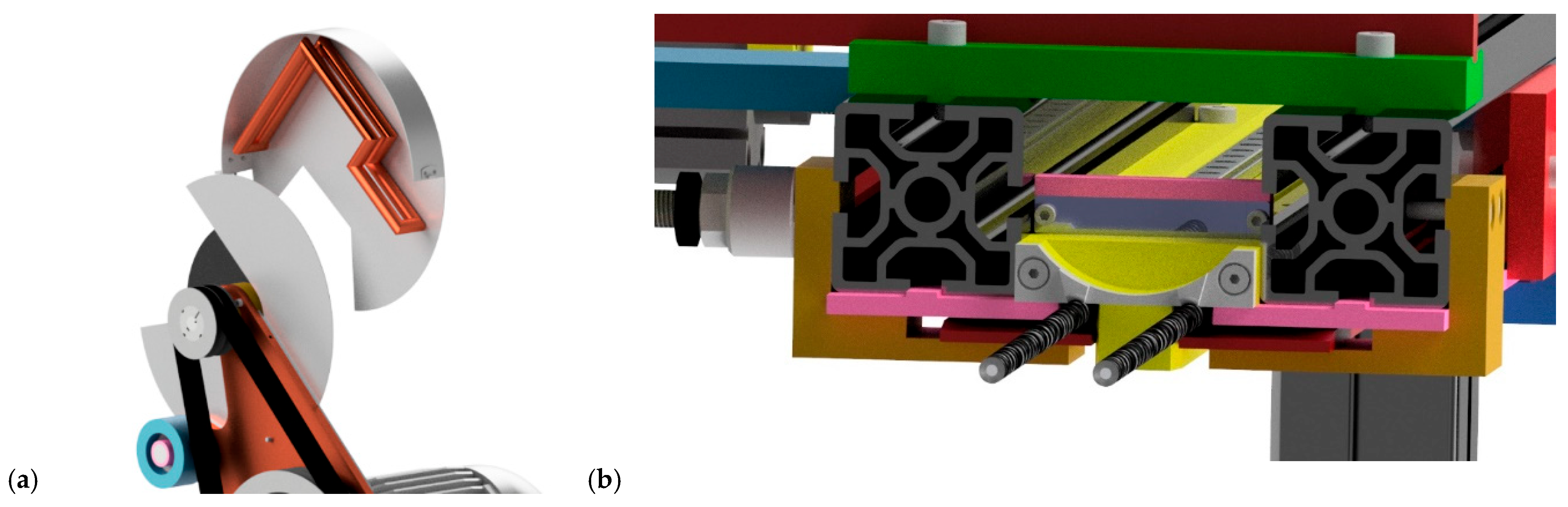
3.3.1. Cutting Mechanism
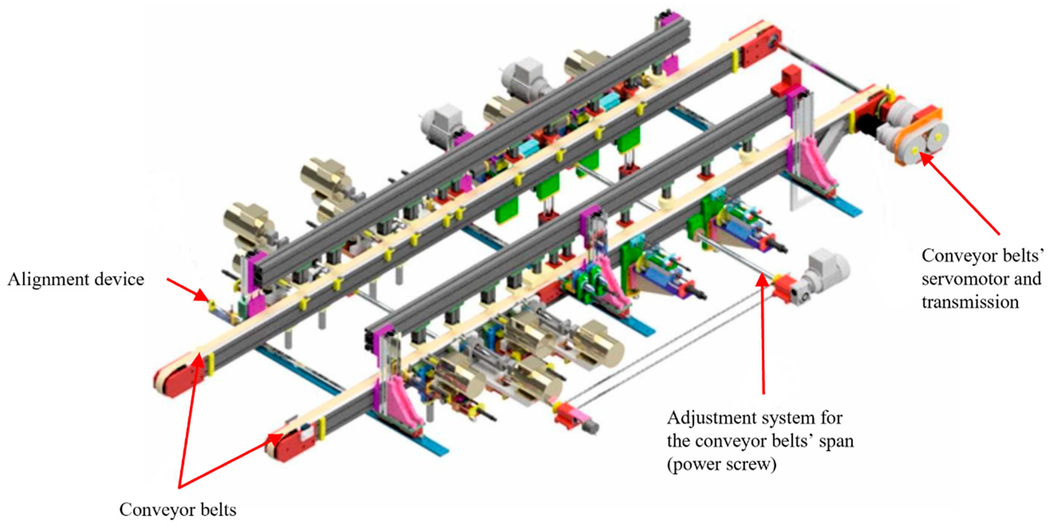
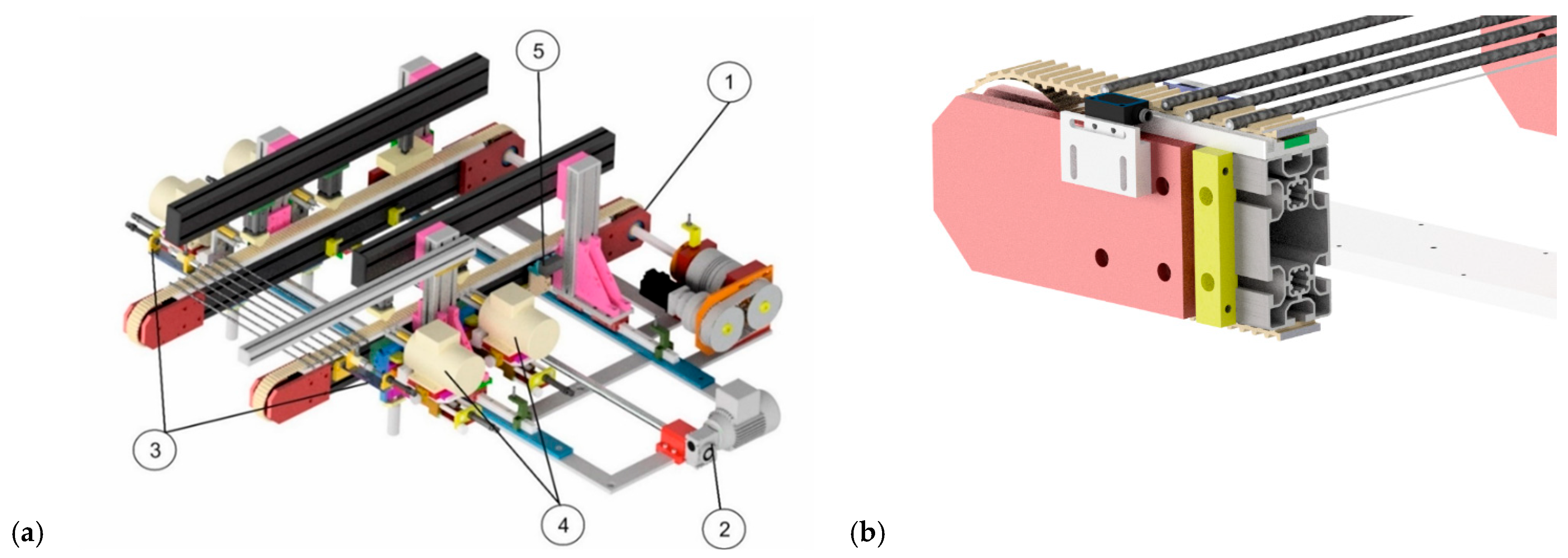
The cutting mechanism (Figure 15) is responsible for dragging/pulling the spirals and cutting them. This mechanism is divided into eight essential systems: (1) drag mechanism, (2) pull system, (3) cutting machine, (4) cutting presser, (5) backstop system, (6) cutting rulers, (7) extraction support system, and (8) detection system.
The drag mechanism (Figure 15-1) leads the spiral into the cutting machine to the pre-defined position, such that it can be cut correctly. The system is activated by a motor that applies the movement through rollers. For a successful cut, the contact time between the spiral and the cut disk should be reduced, since the disk/spiral interaction highly increases the disk temperature, and defects can appear in the spiral’s plastic coating. To reduce the contact time, a pull system was created (Figure 15-2), which promotes the removal of the spiral immediately after the cut. A pneumatic actuator is used to lock the spiral during the cut in the first time. A spring system is used to induce a tensile axial load in the spiral during the cut process and, when it is possible, the spiral recedes. The spirals are cut in the cutting machine (Figure 15-3) using an abrasive disk driven by an electric motor/belt system. The cutting disc used is aluminum oxide with an outside diameter of 180 mm, a thickness of 1 mm, and a grit of 60. Such a disc should operate at cutting speeds below 80 m/s and below 8500 rpm [36]. A servomotor feeds the abrasive disc in the spiral’s direction, while the feed rate used was selected upon testing. The servomotor also allows to compensate for the disc’s wear. The cutting process leads to the deposition of debris that can affect the normal mechanism operation. Currently, metal chips and dust are projected during the process, and most of them lie on the floor and machine, despite all the attempts to mitigate this problem. To remove the debris from the cutting process, including the metal chips and dust, which comprise one of the main problems pointed out in the initial machine due to floor and machine contamination, a disk protection housing is now used that seals the cutting area and directs the debris downwards (by gravity) towards a suction nozzle, to assure the cleanliness of the process. On the other hand, since the temperature of the cutting disk has an influence on the cut quality, a piping system is used to inject atmospheric air directly on the disk, as represented in Figure 16a. Air pumping is made by a centrifugal fan, and the projection to the disk is accomplished by a copper tube, punctured in predefined locations to project air into the cutting disk and cool it by convection.
To remove the hot air generated at the cutting zone and promote the machine cool down, two fans are used in the protection box of the cutting machine (Figure 15-3), enabling the machine to work continuously, while ensuring quality cuts. The cutting presser (Figure 15-4) aims to prevent bending of the spiral, and it is driven by a pneumatic cylinder that lifts it close to the spiral being cut. The backstop system (Figure 15-5) locks the spiral during cutting. While the spirals are cut, they sit on the cutting rulers (Figure 15-6) until they are expelled from the cutting mechanism. In the final stage of the cutting process, pneumatic actuators drop the spiral to the manipulator, and the second phase of the process is started. Figure 16b represents a pair of spirals in the cutting rulers. Since the spirals can get stuck on the cutting rulers, a pneumatic-driven extraction support system (Figure 15-7) is considered, which pushes the spiral down. The length of the spiral to be cut is defined by the operator, using the detection system adjustment (Figure 15-8). This system uses a sensor that is mechanically activated by a paddle system, when the spiral touches it. This system works with the drag mechanism to define the length of the spiral.

3.3.2. Manipulator

The manipulator is the system responsible for transporting the cut spiral between the cutting mechanism and the spiral preparation and cleaning system. The cutting process causes the deposition of debris. Therefore, the belts of the preparation and cleaning system would quickly become dirty if they were placed under the cutting machine, compromising the correct functioning of the system and causing severe production losses. The manipulator was designed to solve this problem and move the spiral in the X and Y axes, as shown in Figure 17a.
Figure 17b shows the assembled manipulator and spiral transfer system. The horizontal movement (in the X direction) is carried out on sliders that move on linear guides, driven by pneumatic cylinders. The X axis makes the movement between two predefined positions: below the cutting mechanism and over the belts of the spiral preparation/cleaning system. The vertical movement (in the Y direction) is also carried out by two pneumatic cylinders fixed to the sliders using a plate. A spiral attachment component is screwed to the cylinders, where the spirals are supported during the mechanism’s operation. A magnet will secure the spirals to this part, preventing them from falling during movement. The Y axis brings the manipulator closer to the cut spiral, to receive it at its ends by two grips, and puts the spiral on the belts when retreating. The described movements work as a cycle and are repeated for each new pair of spirals. The pneumatic cylinders and the linear guides are correctly protected from the cutting debris.

3.3.3. Spiral Preparation and Cleaning System

The cleaning and preparation system is responsible for ensuring a quality finish on the spiral edges. The spiral preparation and cleaning system is based on five mechanisms, represented in Figure 18a: (1) spiral advance system, (2) length tuning system, (3) control positioner, (4) inside and outside cleaning station, and (5) air cleaning station.
The spiral advance system (Figure 18a-1) is a belt-drive mechanism that transports the spiral along the preparation and cleaning system, handling it through the various stations and pushing it, at the end of the process, into an unloading container. To prevent the spirals from falling out during their movement, a magnet system is used to hold the spiral to the conveyor. A photoelectric sensor (Figure 18b) is also used to define the position of the spiral to each processing station, since the detection corresponds to a known distance, to control the feed of the servomotor actuating the belt drive mechanism. Another sensor is included at each station, to trigger the respective operation when a spiral is detected. The length-tuning system (Figure 18a-2) regulates the cutting length automatically, powered by an electric geared motor, to accommodate batches of different spiral lengths. The system slides on two linear guides that hold all of the spiral preparation and cleaning system. The spirals are placed in the system in a misaligned and random position by the manipulator. To be processed correctly, the spirals need a correct alignment. To correct the existing misalignment, a control positioner is used (Figure 18a-3). The system is pneumatically driven, and it aligns the spirals, as shown in more detail in Figure 19a. The spiral preparation and cleaning system contains four inside and outside cleaning stations (Figure 18a-4). These stations work in pairs to clean both ends of each spiral. Each station consists of two parts: the presser and the cleaning system, as shown in Figure 19b. The presser is used to fix the spiral during processing. The cleaning system has a special tool that processes the spiral inside and outside at the same time.
To be correctly positioned and concentric with the spirals, the system can be tuned in three axes. This must be done manually by the operator before starting the machine. To reduce the machine cycle time and increase the working time, each inside and outside cleaning station acts on alternating spirals. Thus, each pair of stations performs the cleaning process for the half of the spirals that pass through it, while the other half are processed by the second pair of stations. This concept is described in Figure 20a: the red spirals are processed by the red cleaning station, and the blue ones are processed by the blue cleaning station.
The air cleaning station (Figure 20b) is the last system through which the spiral passes before leaving the machine (Figure 18a-5). This system aims to unblock the inside of the spiral by injecting compressed air through the interior of the spiral to clean debris. It uses a pressure switch to assess if the spiral is not blocked. If this condition is true, the spiral can be removed from the machine.

3.3.4. Machine Structure

The structure designed to support the cleaning double spiral cutting machine is based on EN AW-6060 aluminum alloy profiles (Figure 21a) due to the long service life, high corrosion resistance, and high strength. The aluminum profiles also can be connected and aligned correctly in a simplified way through universal connectors. Aiming for a higher stiffness in the structure and better positioning between the profiles, aluminum corner connections were implemented, which improve stability (Figure 21b). Leveling feet were used to adjust the height of the mechanisms and correct the misalignment of the floor.

3.3.5. Command System

The command system includes the machine’s control panel, the electrical panel, and the solenoid valve boxes. The machine’s control panel enables the operator-machine interaction. It contains a human-machine interface (HMI) console that provides information about the systems to the operator and allows the operator to trigger the systems. The HMI communicates with a programmable logic controller (PLC) that controls the electronic and pneumatic components of the entire system. The PLC, signal input and output terminals, power supplies, electrical components, and auxiliary components are fundamental to the operation of the machine. The activation of the pneumatic components in the machine is done by solenoid valves. These components transform an electrical signal into a mechanical response. Design of the control system is not presented, since this task will be accomplished by a specialized company, so it is not part of this work’s objectives.

3.3.6. Safety

The double-spiral-cutting machine contains mechanisms that can be dangerous for operators. Thus, it is necessary to create systems capable of guaranteeing the safety of people who circulate in the vicinity of the machine. The operation of the machine must also comply with safety instructions. Aiming to prevent people and objects from approaching the machine mechanisms and protect the machine, a safety barrier was installed (Figure 22).
The barrier is built by pillars that guarantee its fixation to the factory floor and by a mesh that seals the system. The mesh must, however, allow the spirals to enter and exit the machine and, therefore, the entrances and exits represented in Figure 22 were opened. Four doors were added to enable access to the interior of the machine, for maintenance, repairs, or changing the cutting disk. In this way, the safety barrier can be closer to the machine and, thus, allow the machine to occupy as little space as possible in the factory, without preventing access to the machine when necessary.
The access doors installed in the barrier are equipped with safety latches that prevent the door from opening when the machine is in operation. As a result, access to the inside of the protection is only possible when there is no danger to the user. The safety latch is bolted to the structural pillar of the safety barrier, and a trigger is applied to the door, as shown in Figure 23a. When the door is closed, the sensor’s safety latch locks the trigger, and machine operation is allowed. Once in operation, the safety latch does not allow the door to be opened until it receives information that the machine has stopped.
The cutting disk housing has the function of protecting the user during operation. This element is the most dangerous component of the machine, and, therefore, its security system must be studied with greater care. Considering the negligence that may exist by any user of the machine, there is no safety system that prevents the machine from starting when someone is inside. In this sense, it is important to implement an improved safety system for the cutting machine. Thus, the cutting disk housing was also equipped with a safety latch similar to the barrier. This latch prevents the housing from opening when the cutting machine is in operation and the machine from starting while the door is open. Its installation is shown in Figure 23b. The safety latch is fixed to the housing structure and is equipped with an actuator, fixed to the door. The hypothesis of an accident that, for whatever reason, the safety systems have not prevented should also be considered. In this case, there is an emergency button that forces the machine to stop immediately in a controlled manner and as quickly as possible. The emergency button can be deactivated, but the machine is only restarted when the ‘START’ button is pressed. The emergency button must only be used in case of imminent danger to people or equipment. This should never be activated to turn off the machine.
To prevent accidents from occurring, these safety instructions must be followed.
  • The electrical panel must remain closed and prevent access to its interior while the machine is on.
  • Components that show movement must not be moved while the machine is on.
  • The machine must only be operated by users who are familiar with its operation.
  • Safety components must not be removed.
  • The functioning of safety components must be checked regularly.
  • Maintenance actions must be performed with the machine turned off.

4. Discussion and Conclusions

The search for automatic solutions in industrial equipment is associated with increases in productivity and reduction in production costs, which also favors an increase in product quality. Within this scope, this work used the DSR methodology to propose a new machine design that can be easily integrated in the production line to increase the rate of spiral cutting in a control cable assembly line, by cutting and cleaning two spiral cables simultaneously and automatically, thus doubling the productivity associated to this production stage. The machine developed in this paper included different engineering fields to produce a unique and complex system that meets the defined objectives and requirements. When comparing the initial and final machines, and within the scope of stage 6 (conclusions) of the DSR methodology, a significant simplification can be observed, essentially in the preparation and cleaning system, where all unnecessary components were removed, so the required quality output is assured due to the designed mechanism. The preparation and cleaning system, spiral feed from the spool, and cutting length adjustment system are now automatic. At the structural level, simplifications were also made due to the use of aluminum profiles, which facilitate the assembly of the machine; a smaller machine was also proposed, promoting the efficient use of space and simplified construction. Fabrication costs of the new machine were calculated by the company, including all stages from design to assembly, leading to an estimation of EUR 64,000, which gives a 28% reduction in cost compared to the initial design. Operating costs of the machine diminished, since, in terms of cooling, compressed air was replaced by cooling with a fan, and the dedicated operator used in the initial machine for spiral handling is no longer necessary. Still, downtimes for any industrial equipment represent production losses, and, therefore, interruptions for small maintenance actions are to be avoided. In this aspect, the stops made to clean the cutting debris were eliminated due to the implementation of the manipulator. It is, thus, possible to verify that all the imposed requirements were fulfilled.
As a summary of the accomplished work and degree of novelty, a new and original solution, compared to the current state-of-the-art cutting processes, is proposed to improve the productivity of spiral manipulation, cutting, and cleaning, which can be applied to other companies that work in the same field as well as to other fields of engineering in which similar operations such as feeding, cutting, and cleaning are required. As a results, companies can improve their processes and increase competitiveness. It should be mentioned that, for future works, it is still necessary to design the control system, which was out of the scope of the present work, to be executed by a specialized company, as is the common practice in the company. As for future research directions, aiming for the continuous improvement that is essential in the industry for a company to keep competitive, it would be relevant to perform a detailed line balancing analysis, considering the full production process of control cables, to assess the bottlenecks arising from the production rate increase in the spiral-cutting process, to maximize output. Within this topic, the company would also benefit from moving the automatic component between production stages by an integrated pick-and-place transfer system along the assembly line and a respective automatic artificial vision quality inspection station at its end, leading to quality improvement and labor reduction, with a respective cost advantage. On the other hand, in the advent of the mass production of the proposed machine, it would become increasingly relevant to apply the design toward the manufacturing or assembly concepts intended to reduce the fabrication costs of the assembly times. Finally, a complete validation of the solution is only accomplished through prototype construction and physical validation.

Author Contributions

Conceptualization: A.F.G.B. and I.J.S.-A.; investigation, A.F.G.B. and I.J.S.-A.; methodology, R.D.S.G.C.; resources, C.P. and D.B.; supervision, C.P. and D.B.; validation, R.D.S.G.C. and F.J.G.S.; writing—original draft, A.F.G.B. and I.J.S.-A.; writing—review and editing, R.D.S.G.C., F.J.G.S., C.P. and D.B. All authors have read and agreed to the published version of the manuscript.

Funding

This research received no external funding.

Data Availability Statement

Not applicable.

Conflicts of Interest

The authors declare no conflict of interest.

References

  1. Vaz, C.R.; Rauen, T.R.S.; Lezana, Á.G.R. Sustainability and Innovation in the Automotive Sector: A Structured Content Analysis. Sustainability 2017, 9, 880. [Google Scholar] [CrossRef]
  2. Chen, C.-T.; Lien, W.-Y.; Chen, C.-T.; Wu, Y.-C. Implementation of an Upper-Limb Exoskeleton Robot Driven by Pneumatic Muscle Actuators for Rehabilitation. Actuators 2020, 9, 106. [Google Scholar] [CrossRef]
  3. Sousa, V.F.C.; Silva, F.J.G.d.; Campilho, R.D.S.G.; Pinto, A.G.; Ferreira, L.P.; Martins, N. Developing a novel fully automated concept to produce bowden cables for the automotive industry. Machines 2022, 10, 290. [Google Scholar] [CrossRef]
  4. Bowden, E.M. Mechanism for Transmitting Motion or Power. US Patent no. 609570, 23 August 1898. [Google Scholar]
  5. Grosu, S.; Rodriguez-Guerrero, C.; Grosu, V.; Vanderborght, B.; Lefeber, D. Evaluation and analysis of push-pull cable actuation system used for powered orthoses. Front. Robot. AI 2018, 5, 105. [Google Scholar] [CrossRef]
  6. Figueiredo, D.; Silva, F.J.G.; Campilho, R.D.S.G.; Silva, A.; Pimentel, C.; Matias, J.C.O. A new concept of automated manufacturing process for wire rope terminals. Procedia Manuf. 2020, 51, 431–437. [Google Scholar] [CrossRef]
  7. Vieira, A.L.N.; Campilho, R.D.S.G.; Silva, F.J.G.; Faria, N.M.S.; Ferreira, L.P. Design of a thermoplastic micro over injection machine for the automotive component industry. Procedia Manuf. 2021, 55, 56–63. [Google Scholar] [CrossRef]
  8. Chang, X.-D.; Peng, Y.-X.; Cheng, D.-Q.; Zhu, Z.-C.; Wang, D.-G.; Lu, H.; Tang, W.; Chen, G.-A. Influence of different corrosive environments on friction and wear characteristics of lubricated wire ropes in a multi-layer winding system. Eng. Fail. Anal. 2022, 131, 105901. [Google Scholar] [CrossRef]
  9. ISO 2408; 2017-Steel Wire Ropes—Requirements. International Standards Organization: Geneva, Switzerland, 2017.
  10. Oberg, E.; Jones, F.D.; Horton, H.L.; Ryffel, H.H. Machinery’s Handbook, 26th ed.; Industrial Press, INC: New York, NY, USA, 2000. [Google Scholar]
  11. GmbH, C.S. Carl Stahl TECNOCABLES Catalog, 7th ed.; Carl Stahl TECNOCABLES GmbH: Süßen, Germany; Available online: https://www.carlstahl-technocables.com/fileadmin/Resources/Public/Downloads/catalogue_cable_holder_and_suspension_systems.pdf (accessed on 1 August 2022).
  12. Naveen, A.M.; Vishwanatha, H.M. Pneumatic automation of the assembly of spherical bearing and pin header into the gearbox housing. Mater. Today Proc. 2022, in press. [Google Scholar] [CrossRef]
  13. Moreira, B.M.D.N.; Gouveia, R.M.; Silva, F.J.G.; Campilho, R.D.S.G. A novel concept of production and assembly processes integration. Procedia Manuf. 2017, 11, 1385–1395. [Google Scholar] [CrossRef]
  14. Cheng, L.; Tang, Q.; Zhang, L.; Meng, K. Mathematical model and enhanced cooperative co-evolutionary algorithm for scheduling energy-efficient manufacturing cell. J. Clean. Prod. 2021, 326, 129248. [Google Scholar] [CrossRef]
  15. Zhang, X.; Li, Y.; Ran, Y.; Zhang, G. Stochastic models for performance analysis of multistate flexible manufacturing cells. J. Manuf. Syst. 2020, 55, 94–108. [Google Scholar] [CrossRef]
  16. Martins, N.; Silva, F.J.G.; Campilho, R.D.S.G.; Ferreira, L.P. A novel concept of Bowden cables flexible and full-automated manufacturing process improving quality and productivity. Procedia Manuf. 2020, 51, 438–445. [Google Scholar] [CrossRef]
  17. Ribeiro, R.; Silva, F.J.G.; Pinto, A.G.; Campilho, R.D.S.G.; Pinto, H.A. Designing a novel system for the introduction of lubricant in control cables for the automotive industry. Procedia Manuf. 2019, 38, 715–725. [Google Scholar] [CrossRef]
  18. Li, B.; Zhang, S.; Du, J.; Sun, Y. State-of-the-art in cutting performance and surface integrity considering tool edge micro-geometry in metal cutting process. J. Manuf. Processes 2022, 77, 380–411. [Google Scholar] [CrossRef]
  19. Llanto, J.M.; Tolouei-Rad, M.; Vafadar, A.; Aamir, M. Recent Progress Trend on Abrasive Waterjet Cutting of Metallic Materials: A Review. Appl. Sci. 2021, 11, 3344. [Google Scholar] [CrossRef]
  20. Wang, Z.; Xie, T.; Ning, X.; Liu, Y.; Wang, J. Thermal degradation kinetics study of polyvinyl chloride (PVC) sheath for new and aged cables. Waste Manag. 2019, 99, 146–153. [Google Scholar] [CrossRef]
  21. Krar, S.F.; Gill, A.R.; Smid, P. Technology of Machine Tools, 7th ed.; McGraw-Hill: New York, NY, USA, 2011. [Google Scholar]
  22. Mohamed Akeel, A.; Kumar, R.; Chandrasekhar, P.; Panda, A.; Kumar Sahoo, A. Hard to cut metal alloys machining: Aspects of cooling strategies, cutting tools and simulations. Mater. Today Proc. 2022, in press. [Google Scholar] [CrossRef]
  23. Lei, M.K.; Miao, W.L.; Zhu, X.P.; Zhu, B.; Guo, D.M. High-performance manufacturing enabling integrated design and processing of products: A case study of metal cutting. CIRP J. Manuf. 2021, 35, 178–192. [Google Scholar] [CrossRef]
  24. Kalpakjian, S.; Schmid, S.R. Manufacturing Engineering and Technology; Prentice Hall: Hoboken, NJ, USA, 2010. [Google Scholar]
  25. Bhowmik, S.; Naik, R. Selection of Abrasive Materials for Manufacturing Grinding Wheels. Mater. Today Proc. 2018, 5, 2860–2864. [Google Scholar] [CrossRef]
  26. Chen, Z.; Xiao, B.; Wang, B. Optimum and arrangement technology of abrasive topography for brazed diamond grinding disc. Int. J. Refract. Met. Hard Mater. 2021, 95, 105455. [Google Scholar] [CrossRef]
  27. Mitaľová, Z.; Botko, F.; Vandžura, R.; Litecká, J.; Mitaľ, D.; Simkulet, V. Machining of wood plastic composite using AWJ technology with controlled output quality. Machines 2022, 10, 566. [Google Scholar] [CrossRef]
  28. Madić, M.; Petrović, G.; Petković, D.; Antucheviciene, J.; Marinković, D. Application of a robust decision-making rule for comprehensive assessment of laser cutting conditions and performance. Machines 2022, 10, 153. [Google Scholar] [CrossRef]
  29. Copertaro, E.; Perotti, F.; Castellini, P.; Chiariotti, P.; Martarelli, M.; Annoni, M. Focusing tube operational vibration as a means for monitoring the abrasive waterjet cutting capability. J. Manuf. Processes 2020, 59, 1–10. [Google Scholar] [CrossRef]
  30. Naresh; Khatak, P. Laser cutting technique: A literature review. Mater. Today Proc. 2022, 56, 2484–2489. [Google Scholar] [CrossRef]
  31. Krajcarz, D. Comparison Metal Water Jet Cutting with Laser and Plasma Cutting. Procedia Eng. 2014, 69, 838–843. [Google Scholar] [CrossRef]
  32. Vaishnavi, V.K.; Kuechler, W. Introduction to Design Science Research in Information and Communication Technology. In Design Science Research Methods and Patterns; CRC Press: Boca Raton, FL, USA, 2015; pp. 52–91. [Google Scholar]
  33. Abdullah, O.; Abbood, W.; Khalid, H. Development of Automated Liquid Filling System Based on the Interactive Design Approach. FME Trans. 2020, 48, 938–945. [Google Scholar] [CrossRef]
  34. Ashby, M.F. Materials Selection in Mechanical Design; Butterworth-Heinemann: Oxford, UK, 2016. [Google Scholar]
  35. Nunes, D.M.; Campilho, R.; Silva, F.J.G. Design of a transfer system for the automotive industry. Proc. Inst. Mech. Eng. Part E J. Process Mech. Eng. 2022, 236, 5. [Google Scholar] [CrossRef]
  36. Norton. Flat Cutting off Wheel Non-Reinforced Cut-off-Norton NRCO-180x1x31.75-57A60RB25, Product Datasheet. Available online: https://www.nortonabrasives.com/en-gb/ (accessed on 1 August 2022).
Figure 1. Control cable and its main parts and accessories.
Machines 10 00811 g001
Figure 2. Example of cutting machinery already in use in the facilities.
Machines 10 00811 g002
Figure 3. Details of the cutting machine: (a) roller type feeder and (b) sensor to control disk wear.
Machines 10 00811 g003
Figure 4. Scheme of the current cutting system.
Machines 10 00811 g004
Figure 5. Scheme of the current cleaning/post-processing system.
Machines 10 00811 g005
Figure 6. Spiral types: laminated spiral without inner tube (a), push-pull spiral (b), and braided spiral (c).
Machines 10 00811 g006
Figure 7. Laser cutting test results for the laminated spiral without inner tube.
Machines 10 00811 g007
Figure 8. Waterjet cutting without abrasive examples for a laminated spiral without inner tube (a) and a braided spiral (b).
Machines 10 00811 g008
Figure 9. Waterjet cutting with abrasive examples for a push-pull spiral (a) and a braided spiral (b).
Machines 10 00811 g009
Figure 10. Microscopic images for the braided spiral with diamond disk cut: magnification of 40× (a) and 250× (b).
Machines 10 00811 g010
Figure 11. Microscopic images for the laminated spiral with diamond disk cut: magnification of 40× (a) and 250× (b).
Machines 10 00811 g011
Figure 12. Microscopic images for the laminated spiral with abrasive disk cut: magnification of 40× (a) and 250× (b).
Machines 10 00811 g012
Figure 13. Arrangement of the main systems in the machine.
Machines 10 00811 g013
Figure 14. Arrangement of the secondary components in the machine.
Machines 10 00811 g014
Figure 15. Layout of the cutting mechanism.
Machines 10 00811 g015
Figure 16. Cutting disk cooler system (a) and schematic of the cutting rulers (b).
Machines 10 00811 g016
Figure 17. Schematic of the manipulator (a) and assembled manipulator and spiral transfer system (b).
Machines 10 00811 g017
Figure 18. Spiral preparation and cleaning system (a) and magnet system and photelectric sensor (b).
Machines 10 00811 g018
Figure 19. Alignment of spirals before and after the control positioner (a) and inside and outside cleaning station (b).
Machines 10 00811 g019
Figure 20. Processing of the spirals (a) and air cleaning station (b).
Machines 10 00811 g020
Figure 21. Machine structure (a) and corner connections (b).
Machines 10 00811 g021
Figure 22. Safety barrier for the machine.
Machines 10 00811 g022
Figure 23. Safety latch for the machine access doors (a) and cutting disk housing’s safety latch (b).
Machines 10 00811 g023
Table 1. Selection matrix for the choice of spiral cutting process.
ViΩi1—Cutting quality5—Heat
Generation
2—Cutting time4—Cost3—Process
know-how
Final Classification
βi
ω10.33ω50.24ω20.18ω40.15ω30.1γi
Laser319.8419.2414.426.012.061.4
60.080.080.040.020.0
Waterjet319.8524.0310.813.012.059.6
60.0100.060.020.020.0
Diamond disc533.029.6518.039.048.077.6
100.040.0100.060.080.0
Abrasive disk with cooling533.029.6518.0515.0510.085.6
100.040.0100.0100.0100.0
Publisher’s Note: MDPI stays neutral with regard to jurisdictional claims in published maps and institutional affiliations.

