
Multi-Objective Optimization of Process Parameters in Longitudinal-Torsional Ultrasonic Vibration Face Grinding CFRP


School of Advanced Manufacturing Engineering, Chongqing University of Posts and Telecommunications, Chongqing 400065, China
*
Author to whom correspondence should be addressed.
Machines 2023, 11(10), 935; https://doi.org/10.3390/machines11100935
Submission received: 5 September 2023
/
Revised: 24 September 2023
/
Accepted: 28 September 2023
/
Published: 29 September 2023
(This article belongs to the Section Material Processing Technology)
Abstract
:Due to its superior characteristics, carbon fiber reinforced plastics (CFRP) have been widely used in aerospace and other fields. However, their effective and economical processing remains a challenge. The purpose of this paper was to experimentally investigate the influence of several machining parameters, namely spindle speed, cutting depth, feed rate, and grit size on different machining performances, i.e., grinding force, and surface roughness through longitudinal-torsional (L&T) ultrasonic vibration grinding CFRP. The response surface methodology with a Box—Behnken design was used to create the experiments. The fitting mathematical models of grinding force and surface roughness were established separately to explore the interaction between the machining parameters and the impact on machining results. With the purpose of improving the surface quality and reducing the grinding force, the NSGA-II was used for multi-objective optimization to obtain the Pareto optimal solution. Compared with the initial experimental parameters, the optimized results can significantly improve the surface roughness and reduce the cutting force.
1. Introduction
Carbon fiber reinforced plastics (CFRP), as a special type of advanced composite material, have a wide demand in fields such as aerospace, lightweight vehicles, and high-end equipment [1,2]. However, due to the anisotropy, high strength, and high temperature resistance of CFRP materials, the machining of CFRP is considerably more difficult than the machining of conventional metals. Generally, conventional machining (CM) of CFRP encounters many issues such as delamination, burrs, splintering, excessive cutting forces, low machining precision, and short tool life [3,4,5]; the surface morphology and reliability of CFRP components have been greatly affected.
In recent years, ultrasonic vibration machining (UVM) has received extensive research, which can improve machining efficiency, effectively reduce cutting force and temperature, and greatly improve machining quality. Ultrasonic vibration machining (UVM) is a nontraditional machining process which is a hybrid process that combines material removal mechanisms of CM and ultrasonic machining. The cutting tool can oscillate at a high frequency (typically 20 kHz) [6]. UVM has been considered an excellent machining method for CFRP materials, which has been studied in mechanical process areas, such as ultrasonic-assisted cutting [7,8,9], ultrasonic-assisted drilling [10,11,12], ultrasonic milling [13,14], and ultrasonic-assisted grinding [15,16], etc.
Compared to ordinary grinding, L&T ultrasonic vibration face grinding is beneficial for maintaining the good cutting performance of abrasive particles [17]. The abrasive particles undertake an approximate spiral motion in three-dimensional space, resulting in periodic cutting separation motion between the abrasive particles and the workpiece, which further refines the chips and is more conducive to obtaining high-precision and high-quality machining surfaces.
Improving the surface processing accuracy and optimizing the processing technology of CFRP is an important and arduous task. Scholars have conducted experimental research on multiple types of machining methods, mechanisms, and processes. The various influencing factors of CFRP surface roughness and cutting force have been analyzed. Exploring the optimal machining process plan has become a current research hotspot.
GENG et al. [18] studied the processing technology of rotating ultrasonic elliptical machining of CFRP; the delamination suppression mechanism in this process was analyzed and verified. Rotating ultrasonic elliptical machining was considered as a competitive and promising technique for drilling CFRP. CHEN et al. [19] studied the effect of the angle between the fiber direction and the grinding direction on the grinding force as well as the surface integrity of ultrasonic vibration-assisted grinding of CFRP. When the included angle was 45°, the extraction of fibers and grinding force was effectively reduced. Moreover, ultrasonic vibration can efficaciously improve the sharpness of the abrasive particles and reduce the fiber fracture phenomenon. WANG et al. [20] constructed a mathematical model for the grinding force of two-dimensional elliptical ultrasonic vibration-assisted grinding of CFRP. The elastic modulus of fiber in the transverse and longitudinal directions was first calculated. Considering the trajectory of abrasive particles and the mechanism of material removal, the relationship between the grinding force and the machining parameters was established. The results indicated that horizontal ultrasonic vibration mainly reduced the actual contact time between the abrasive particles and the workpiece, while vertical ultrasonic vibration increased the length of contact time between the abrasive particles and the workpiece, ultimately leading to a decrease in the grinding force.
In addition to the research on machining mechanisms and process methods, some scholars have studied the influence of cutting parameters on machining performance indexes and preferably selected the optimal range of cutting parameters to improve the machining efficiency, enhance the surface quality, and reduce the cutting force. These are important for controlling the surface machining accuracy and for seeking reasonable machining process solutions.
Niu et al. [21] studied multi-objective optimization for longitudinal and torsional ultrasonic vibration milling of titanium alloys. A multi-objective optimization model was established to obtain optimization parameters. Based on the optimization results, a set of milling-validated experiments were developed to optimize the model. Sindhu et al. [22] studied the effects of tool feed rate, spindle speed, and material removal rate of surface roughness through rotary ultrasonic vibration machining. Through grey relational analysis, the results showed that tool feed rate was the most critical parameter affecting the characteristics of rotary ultrasonic machining, followed by ultrasonic power and tool speed. Finally, the optimal machining parameters were provided. The optimization studies [23] were carried out for the ultrasonic machining process with multi-response characteristics dependent on the multi-criteria decision making methodology (MCDM), using a technique to order the preference via similarity to the ideal solution (AHP-TOPSIS) approach as described. Singh and Singhal [24] investigated spindle speed, feed rate, coolant pressure, and ultrasonic power dominance in different machining performances based on the feedback of surface roughness and the chipping in alumina-ceramic rotary ultrasonic machines. Surface method found that the surface roughness value was 0.215 mm and the chipping thickness was 0.159 mm. Singh et al. [25] proposed the multiple response optimization of the ultrasonic-assisted electric discharge machining (UAEDM) process through the Taguchi—Grey relational analysis approach, during machining of a Nimonic 75 superalloy. Kumar et al. [26] selected feed rate, tool rotation speed, and ultrasonic power as input variables considering the chipping width, taper and material removal rate (MRR) as output responses. The TOPSIS approach was coupled with the Taguchi approach for multi-response optimization. Choi et al. [27] conducted experimental research on rotary ultrasonic side milling (RUSM) quartz materials based on the response surface methodology (RSM) with a Box—Behnken design for the experiments. The predicted equations for the cutting force according to the machining environments and conditions were proposed and the optimal conditions were obtained.
As per the reported literature, only a few research studies have been conducted on L&T ultrasonic vibration machining of CFRP that employed the response surface methodology (RSM) with a view to scheme the experiments and to assess the parameters’ influences on the process responses. Multi-response optimization of machining characteristics, i.e., surface roughness (SR) and grinding force (GF), had also never been attempted before in L&T ultrasonic vibration face grinding of CFRP. This paper mainly studied the influence and interaction of longitudinal-torsional (L&T) ultrasonic vibration grinding parameters on the surface quality of CFRP. Based on the response surface design method, mathematical models of grinding force and surface roughness were established. The influence of the grinding parameters on the cutting force and roughness were also analyzed. Moreover, the significant order of spindle speed, cutting depth, feed rate, and grit size in the experimental space was obtained for the purpose of improving the surface quality and to reduce the grinding force. The evolutionary algorithm of the multi-objective optimization problem (non-dominated sorting genetic algorithm, NSGA-II) was used to explore the complex relationship between the grinding parameters and the CFRP surface quality and grinding force. Finally, these optimization results were compared with the experimental results. This research provides a theoretical basis for the high quality and efficient processing of CFRP components.
2. Experimental Conditions and Methods
2.1. Experimental Set-Up and Conditions
The end grinding experiments were carried out on a vertical CNC machining center HAAS VF-2SS, with a spindle power of 11.2 kW and a maximum speed of 20,000 r/min. It should be emphasized that the original spindle was replaced by the designed ultrasonic spindle system. The ultrasonic spindle system was composed of a piezoelectric transducer, a collector ring, a horn, and a diamond grinding unit. Ultrasonic vibration is defined as high-frequency and low amplitude reciprocal harmonic motion, generated through a piezoelectric transducer with a sinusoidal voltage signal input from the ultrasonic generator. Then, the horn amplified the amplitude to 8 (longitudinal vibration) and to 4 (torsional vibration) at a frequency of 20 kHz.
The grinding tool adopted a cylindrical electroplated diamond grinding head, with a particle size of 60/100/120/150/200 mesh # (mesh size). The model characteristics of the grinding unit are shown in Table 1.
2.2. Materials
2.3. Material Measurement Procedures for Output Variables
The grinding forces generated during the process were measured using a Kistler 9257B piezoelectric grinding dynamometer and a multi-channel charge amplifier (Kistler 5080) connected to the grind table. Data transfer from the piezoelectric dynamometer was provided via the data acquisition system (DEWE soft SIRIUS). Data transfer was based on the logic of converting analog signals into digital signals. The average value of the grinding force was chosen to represent the entire cutting force. The experimental processing site is shown in Figure 2. The grinding force obtained from the experimental measurement is shown in Figure 3: for a 1500 rpm spindle speed, it utilized a 0.15 mm cutting depth, a 180 mm/min feed rate, and a 120# grit size. This figure shows the cutting force in the time domain from 3 s to 7.5 s. It was evident that the grinding force value tended to stabilize during this time period. The extreme value in the curve was used as the experimental measurement result of the grinding force.
The surface arithmetic mean deviation was used to evaluate the surface processing quality of CFRP. It considered all the measurement points on the surface to be measured and truly reflected the surface condition of the workpiece. The surface roughness measurement was taken using a VK-X200K laser confocal microscope.
To ensure the accuracy and reliability of the measurement data, the specific measurement method took three positions on the machining surface for measurement, and then calculated the average value to obtain the surface roughness value.
2.4. Experimental Design
The Response Surface Methodology (RSM) combines mathematical and statistical techniques to save costs and time through conducting fewer experiments. It maps the relationship between the response and the factors into a mathematical model, analyzes the influence of factors on the response, and obtains the optimal response factor value. When researchers search for the optimal value of the response, they usually need a model that includes curvature to approximate the predicted response. In general, the second-order model form of Equation (1) is adopted.
where represents the output response variable; were the constants calculated using the least square methodology. were the linear, second order and interaction terms of the process parameters and k represented the number of variables.
The Box—Behnken Design has been widely used in experimental design methodologies in RSM, which is very suitable for fitting second-order models. The four parameters utilized in this experiment were spindle speed, cutting depth, feed rate, and grit size (mesh #). The responses used were grinding force and surface roughness, which have interacted in this experiment.
The number of center points per block was set to 6. Preliminary experiments were performed several times to select parameters. Table 3 shows the parameter values corresponding to each level. A total of 30 experiments were conducted. Table 4 presents the complete experimental design plan along with the values of grinding force and surface roughness.
3. Results and Discussions
3.1. ANOVA
Analysis of variance (ANOVA) testing confirmed the importance and contribution of each process parameter on the output response. The p-value was the probability of ( was the confidence level, was the number of fitted model factor terms, and was the number of experimental data). When the p-value (<0.0500) corresponded to a confidence level of over 95%, it was considered that the corresponding source of variance had a significant impact on the results.
3.1.1. Grinding Force Analysis and Prediction
The regression analysis was carried out on the experimental data and is presented in Table 4. According to the principles of ANOVA mentioned earlier, significant models for the grinding force with the insignificant terms removed were created and are listed in Table 5. In this table, the p-value of this model was less than 0.0001, which indicated that the established model had a high fitness.
A general second order model for predicting grinding force was generated using the least square method:
where was the grinding force, was the spindle speed, was cutting depth, was feeding rate, and was the grit size of the grinding unit. The normal probability plot given in Figure 4 shows that the model for grinding force was consistent with the regression and that the residues were distributed normally.
Based on Table 5, the significant order of spindle speed, cutting depth, feed rate, and grit size of the grinding unit in the experimental space was obtained as follows: A > B > D > C (primary term), A2 > AC > CD > C2 > AD > B2 > BC (quadratic term).
Figure 5 shows the response surface with the most significant interaction between the grinding parameters and the grinding force. From Figure 5, it can be concluded that the spindle speed was the most influential parameter that impacted the grinding force. The grinding force was significantly increased with the increased spindle speed, and the influence of cutting depth, grit size, and feed rate on the grinding force decreased in sequence.
3.1.2. Surface Roughness Analysis and Prediction
The regression analysis was carried out on the experimental data and is presented in Table 4. According to the principles of ANOVA mentioned earlier, significant models for the surface roughness with the insignificant terms removed are listed in Table 6. In this table, the p-value of this model was less than 0.0001, which indicated that the established model had a high fitness. A general second order model for predicting surface roughness was generated using the least square method:
where, was the surface roughness. The normal probability plot given in Figure 6 shows that the model for surface roughness was consistent with the regression and the residues were distributed normally.
Based on Table 6, the significant order of spindle speed, cutting depth, feed rate, and grit size of the grinding unit in the experimental space was obtained as follows: A > B > C > D (primary term), A2 > D2 > C2 > BC > B2 > AC > BD > CD > AD >AB (quadratic term).
Figure 7 shows the response surface with the most significant interaction between the grinding parameters and the surface roughness. From Figure 7, it can be concluded that the influence of spindle speed on roughness was the most significant. Roughness decreased significantly by increasing the spindle speed, while as cutting thickness and feed speed increase, the roughness also increased. The effect of grit size on the roughness was relatively weak.
3.2. Multi-Objective Optimization via NSGA-II
For industrial applications, obtaining the processing skills that can simultaneously optimize multiple objectives has become very urgent. This paper optimized the objective functions and yet did not achieve the minimum simultaneously; there was no solution that optimized both objectives simultaneously, only a Pareto optimal solution set that balanced the two optimization objectives.
Based on the quadratic polynomial model established via RSM, NSGA-II was used to optimize the parameters of ultrasonic vibration grinding. Therefore, the optimal design of L&T ultrasonic vibration face grinding of CFRP was divided into the two following steps.
- Find the Pareto optimal solution set.
- Compare the evaluation results of all elements in the Pareto optimal solution set and select the best solution that is closest to the optimal level (with two objectives simultaneously optimal).
3.2.1. Models of Multi-Objective Optimization
Quadratic models from RSM were used as objective functions for multi-objective optimization, and spindle speed , cutting depth , feed rate , and grit size served as design parameters. The mathematical model and constraints for the multi-objective optimization design of the ultrasonic technology were expressed as
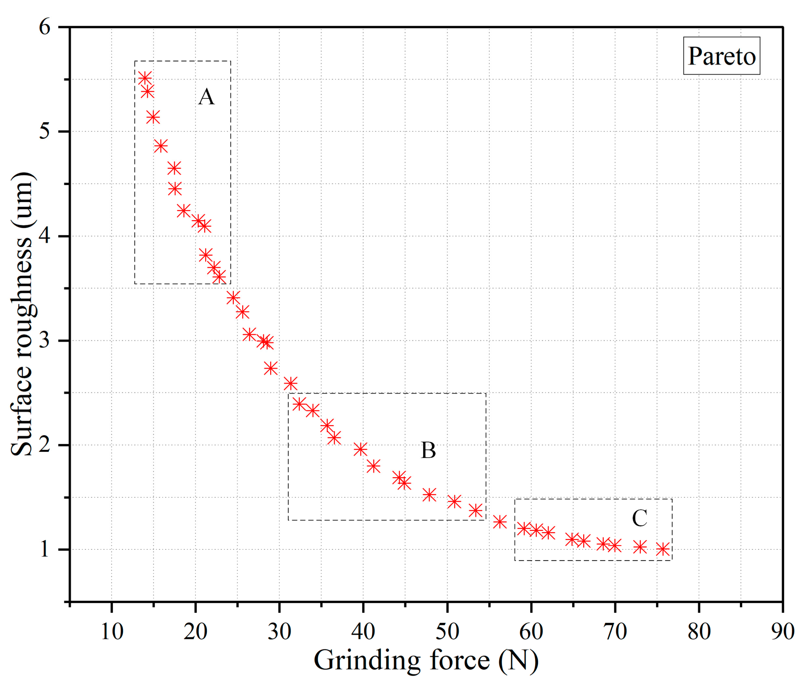
The NSGA-II algorithm initialized a population size of 50 and had an evolution iteration count of 200. The obtained Pareto optimal solution set is shown in Figure 8, with the X axis and Y axis representing and , respectively. As shown in Figure 8, at the Pareto front, when one response changed, the other response also changed. It was obvious that as grinding force increased, the corresponding surface roughness also decreased.
In Figure 8, the surface roughness in region A decreased rapidly, while the grinding force increased less, indicating a decline in grinding force. In the C region, the grinding force increased rapidly, while the surface roughness had a relatively small decrease, belonging to the surface roughness growth zone. In the B region, lower surface roughness was achieved while also achieving satisfactory grinding force values. Therefore, using region B as the optimization region balanced the surface roughness and grinding force. The Pareto solution set for the optimization region is shown in Table 7.
It should be noted that there may be slight differences in the results of each run due to the characteristics of the algorithm. Suitable grinding parameter combinations can be selected according to actual needs. For example, when the specified grinding force cannot exceed 80 N, the minimum surface roughness that can be achieved is 1.374 .
3.2.2. Optimization Results Discussion
In order to verify the effectiveness of multi-objective optimization, the parameter combination at the center point level of the experiment (, , , ) was used as the initial parameter combination and was compared with some Pareto optimal solutions. The results are shown in Table 7. It can be seen that when the 12th group of experimental parameters in Table 7 was taken, the predicted grinding force was 52.383 N, surface roughness was 1.374 , grinding force increased by 106.23%, while surface roughness decreased by 47.18%. Therefore, within the allowable range of the grinding force, the application of this optimization model effectively reduced the surface roughness and obtained increased surface quality.
4. Conclusions
In this study, longitudinal-torsion ultrasonic vibration was composited to the grinding of CFRP. L&T ultrasonic vibration face grinding experiments were proposed to evaluate the influence of the machining parameters on grinding force and surface roughness. Multi-objective optimization was carried out with the goal of analyzing grinding force and surface roughness. The conclusions of this study can be summarized as follows.
- Using the Box—Behnken design method in RSM to analyze the influence of various cutting parameters on the machining results, it was concluded that the spindle speed had a marked impact on the cutting force and the surface roughness. The influence of the cutting depth, grit size and feed rate on the machining results decreased in sequence.
- Regression equations obtained through general full factorial design of parameters affecting the surface roughness and the cutting forces were obtained. A statistical mathematical model with high predictive power was created, which effectively predicted the grinding force and surface roughness during the L&T ultrasonic vibration face grinding process.
- With the purpose of minimizing the grinding force and surface roughness, the NSGA-II algorithm was used for multi-objective optimization. Compared with the initial experimental parameters, the optimized results significantly improved surface roughness and reduced cutting force. Moreover, this optimization model has a high level of accuracy and application value, and can provide optimization solutions for different industrial requirements.
Author Contributions
S.L.: experimentation, data curation, and writing the original draft. K.Z.: conceptualization, and methodology. H.L.: manuscript revision. Z.C.: funding acquisition. S.Z.: experimentation and methodology. All authors have read and agreed to the published version of the manuscript.
Funding
This work was financially sponsored by the Science and Technology Department of Chongqing (Grant Number: cstc2019jcyj-msxmX0559, cstc2020jcyj-msxmX1004), the Chongqing Education Commission (Grant Number: KJQN202000613) and National Natural Science Foundation of China (Grant Number: 51905065).
Data Availability Statement
Not applicable.
Conflicts of Interest
The authors declare no competing interest. The funders had no role in the design of the study; in the collection, analyses, or interpretation of data; in the writing of the manuscript; or in the decision to publish the results.
References
- Aamir, M.; Tolouei-Rad, M.; Giasin, K.; Nosrati, A. Recent advances in drilling of carbon fiber–reinforced polymers for aerospace applications: A review. Int. J. Adv. Manuf. Technol. 2019, 105, 2289–2308. [Google Scholar] [CrossRef]
- Asmael, M.; Safaei, B.; Zeeshan, Q.; Zargar, O.; Nuhu, A.A. Ultrasonic machining of carbon fiber–reinforced plastic composites: A review. Int. J. Adv. Manuf. Technol. 2021, 113, 3079–3120. [Google Scholar] [CrossRef]
- Liu, J.; Che, G.; Ji, C.; Qin, X.; Li, H.; Ren, C. An investigation of workpiece temperature variation of helical milling for carbon fiber reinforced plastics (CFRP). Int. J. Mach. Tools Manuf. 2014, 86, 89–103. [Google Scholar] [CrossRef]
- Rodríguez, A.; Calleja, A.; de Lacalle, L.L.; Pereira, O.; Rubio-Mateos, A.; Rodríguez, G. Drilling of CFRP-Ti6Al4V stacks using CO2-cryogenic cooling. J. Manuf. Process. 2021, 64, 58–66. [Google Scholar] [CrossRef]
- Lopez de Lacalle, N.; Lamikiz, A.; Campa, F.J.; Valdivielso, A.F.; Etxeberria, I. Design and test of a multitooth tool for CFRP milling. J. Compos. Mater. 2009, 43, 3275–3290. [Google Scholar] [CrossRef]
- Suárez, A.; Veiga, F.; de Lacalle, L.N.L.; Polvorosa, R.; Lutze, S.; Wretland, A. Effects of ultrasonics-assisted face milling on surface integrity and fatigue life of Ni-Alloy 718. J. Mater. Eng. Perform. 2016, 25, 5076–5086. [Google Scholar] [CrossRef]
- Shamoto, E.; Moriwaki, T. Study on Elliptical Vibration Cutting. CIRP Ann. -Manuf. Technol. 1994, 43, 35–38. [Google Scholar] [CrossRef]
- Celaya, A.; Lopez de Lacalle, L.N.; Campa, F.J.; Lamikiz, A. Ultrasonic Assisted Turning of mild steels. Int. J. Mater. Prod. Technol. 2010, 37, 60–70. [Google Scholar] [CrossRef]
- Geng, D.; Lu, Z.; Yao, G.; Liu, J.; Li, Z.; Zhang, D. Cutting temperature and resulting influence on machining performance in rotary ultrasonic elliptical machining of thick CFRP. Int. J. Mach. Tools Manuf. 2017, 123, 160–170. [Google Scholar] [CrossRef]
- Pujana, J.; Rivero, A.; Celaya, A.; De Lacalle, L.L. Analysis of ultrasonic-assisted drilling of Ti6Al4V. Int. J. Mach. Tools Manuf. 2009, 49, 500–508. [Google Scholar] [CrossRef]
- Geng, D.; Teng, Y.; Liu, Y.; Shao, Z.; Jiang, X.; Zhang, D. Experimental study on drilling load and hole quality during rotary ultrasonic helical machining of small-diameter CFRP holes. J. Mater. Process. Technol. 2019, 270, 195–205. [Google Scholar] [CrossRef]
- Cao, S.; Li, H.N.; Huang, W.; Zhou, Q.; Lei, T.; Wu, C. A delamination prediction model in ultrasonic vibration assisted drilling of CFRP composites. J. Mater. Process. Technol. 2022, 302, 117480. [Google Scholar] [CrossRef]
- Yashiro, T.; Ogawa, T.; Sasahara, H. Temperature measurement of cutting tool and machined surface layer in milling of CFRP. Int. J. Mach. Tools Manuf. 2013, 70, 63–69. [Google Scholar] [CrossRef]
- Amin, M.; Yuan, S.; Israr, A.; Zhen, L.; Qi, W. Development of cutting force prediction model for vibration-assisted slot milling of carbon fiber reinforced polymers. Int. J. Adv. Manuf. Technol. 2018, 94, 3863–3874. [Google Scholar] [CrossRef]
- Ning, F.; Cong, W.; Wang, H.; Hu, Y.; Hu, Z.; Pei, Z. Surface grinding of CFRP composites with rotary ultrasonic machining: A mechanistic model on cutting force in the feed direction. Int. J. Adv. Manuf. Technol. 2017, 92, 1217–1229. [Google Scholar] [CrossRef]
- Shi, H.; Yuan, S.; Zhang, C.; Chen, B.; Li, Q.; Li, Z.; Qian, J. A cutting force prediction model for rotary ultrasonic side grinding of CFRP composites considering coexistence of brittleness and ductility. Int. J. Adv. Manuf. Technol. 2020, 106, 2403–2414. [Google Scholar] [CrossRef]
- Wang, J.; Feng, P.; Zhang, J.; Guo, P. Reducing cutting force in rotary ultrasonic drilling of ceramic matrix composites with longitudinal-torsional coupled vibration. Manuf. Lett. 2018, 18, 1–5. [Google Scholar] [CrossRef]
- Geng, D.; Liu, Y.; Shao, Z.; Zhang, M.; Jiang, X.; Zhang, D. Delamination formation and suppression during rotary ultrasonic elliptical machining of CFRP. Compos. Part B Eng. 2020, 183, 107698. [Google Scholar] [CrossRef]
- Chen, Y.; Liang, Y.; Xu, J.; Hu, A. Ultrasonic vibration assisted grinding of CFRP composites: Effect of fiber orientation and vibration velocity on grinding forces and surface quality. Int. J. Lightweight Mater. Manuf. 2018, 1, 189–196. [Google Scholar] [CrossRef]
- Wang, H.; Pei, Z.J.; Cong, W. A feeding-directional cutting force model for end surface grinding of CFRP composites using rotary ultrasonic machining with elliptical ultrasonic vibration. Int. J. Mach. Tools Manuf. 2020, 152, 103540. [Google Scholar] [CrossRef]
- Niu, Y.; Jiao, F.; Zhao, B.; Wang, D. Multiobjective optimization of processing parameters in longitudinal-torsion ultrasonic assisted milling of Ti-6Al-4V. Int. J. Adv. Manuf. Technol. 2017, 93, 4345–4356. [Google Scholar] [CrossRef]
- Sindhu, D.; Thakur, L.; Chandna, P. Multiobjective optimization of rotary ultrasonic machining parameters for quartz glass using Taguchi-Grey relational analysis (GRA). Silicon 2019, 11, 2033–2044. [Google Scholar] [CrossRef]
- Banerjee, B.; Mondal, K.; Adhikary, S.; Paul, S.N.; Pramanik, S.; Chatterjee, S. Optimization of process parameters in ultrasonic machining using integrated AHP-TOPSIS method. Mater. Today Proc. 2022, 62, 2857–2864. [Google Scholar] [CrossRef]
- Singh, R.P.; Singhal, S. Experimental study on rotary ultrasonic machining of alumina ceramic: Microstructure analysis and multi-response optimization. Proc. Inst. Mech. Eng. Part L J. Mater. Des. Appl. 2018, 232, 967–986. [Google Scholar] [CrossRef]
- Singh, M.; Singh, S. Multiple response optimization of ultrasonic assisted electric discharge Machining of Nimonic 75: A Taguchi-Grey relational analysis approach. Mater. Today Proc. 2021, 45, 4731–4736. [Google Scholar] [CrossRef]
- Kumar, V.; Singh, H. Rotary ultrasonic Drilling of Silica Glass BK-7: Microstructural investigation and process optimization through TOPSIS. Silicon 2019, 11, 471–485. [Google Scholar] [CrossRef]
- Choi, S.J.; Lee, C.M.; Kim, D.H. Experimental investigation for multiresponse optimization in rotary ultrasonic side milling of quartz. Int. J. Adv. Manuf. Technol. 2022, 122, 1583–1597. [Google Scholar] [CrossRef]
Figure 1.
Illustration of CFRP Specimen.
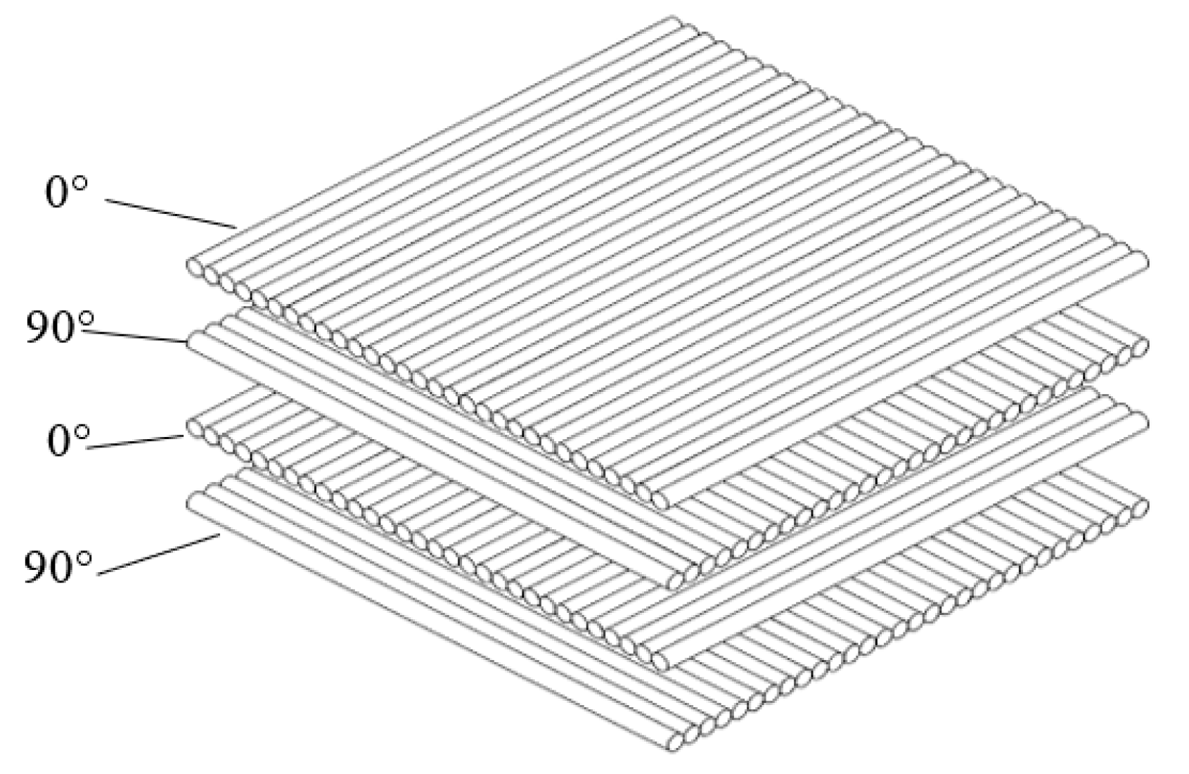
Figure 2.
Experimental set-up.
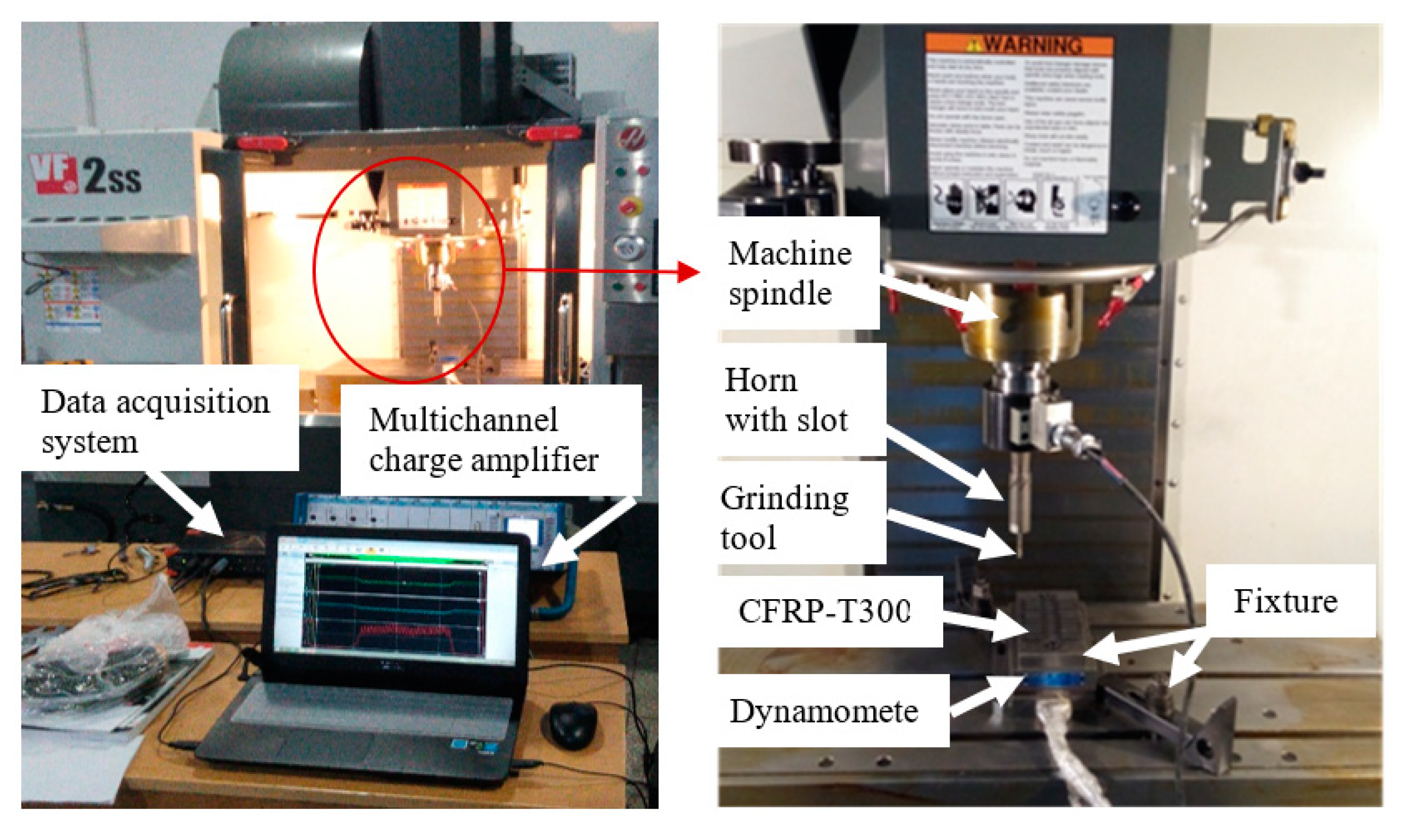
Figure 3.
Experimental value of grinding force (for a 1500 rpm spindle speed, it utilized a 0.15 mm cutting depth, a 180 mm/min feed rate, a 120# grit size).
Figure 3.
Experimental value of grinding force (for a 1500 rpm spindle speed, it utilized a 0.15 mm cutting depth, a 180 mm/min feed rate, a 120# grit size).
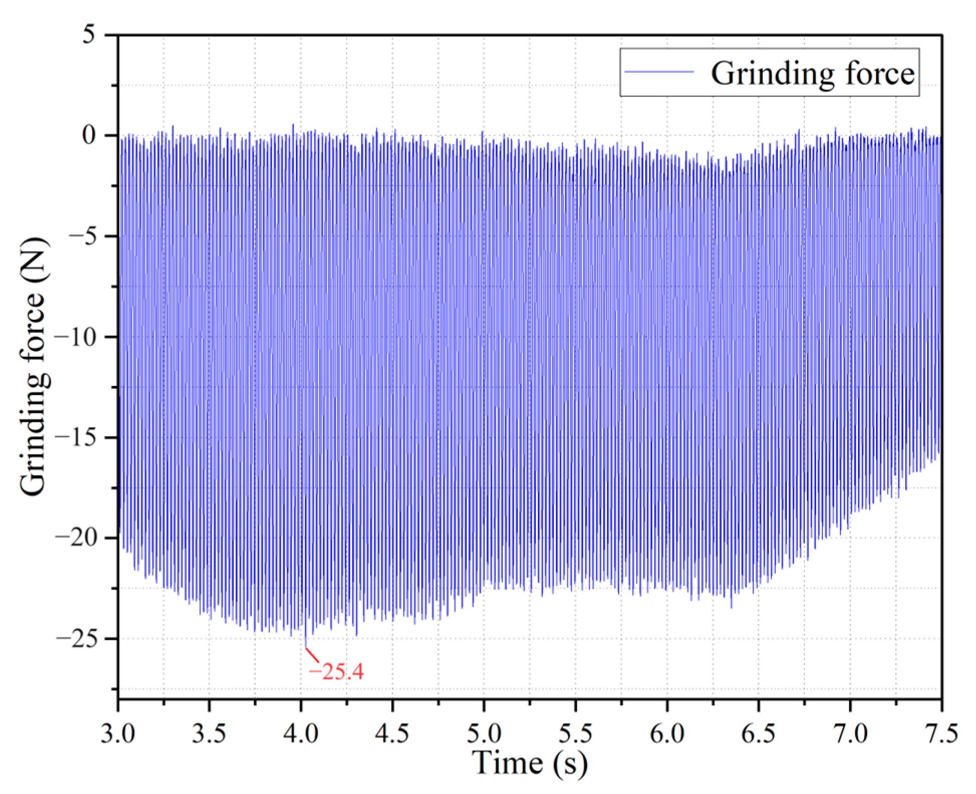
Figure 4.
Normal probability plot for grinding force.
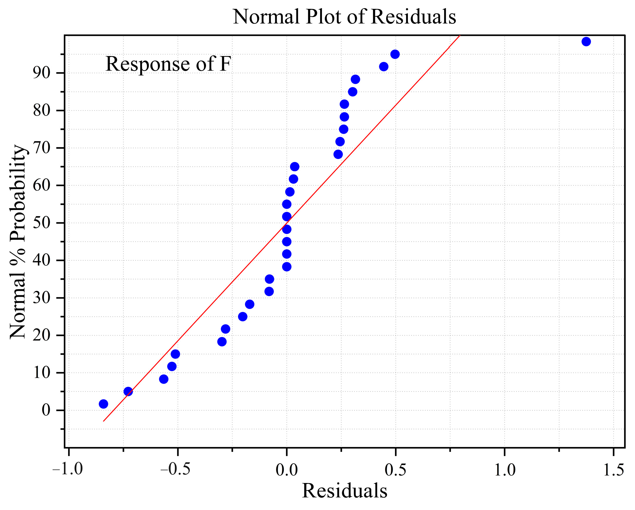
Figure 5.
Two variable interactive effects of spindle speed, cutting depth, feed rate, and grit size on grinding force.
Figure 5.
Two variable interactive effects of spindle speed, cutting depth, feed rate, and grit size on grinding force.
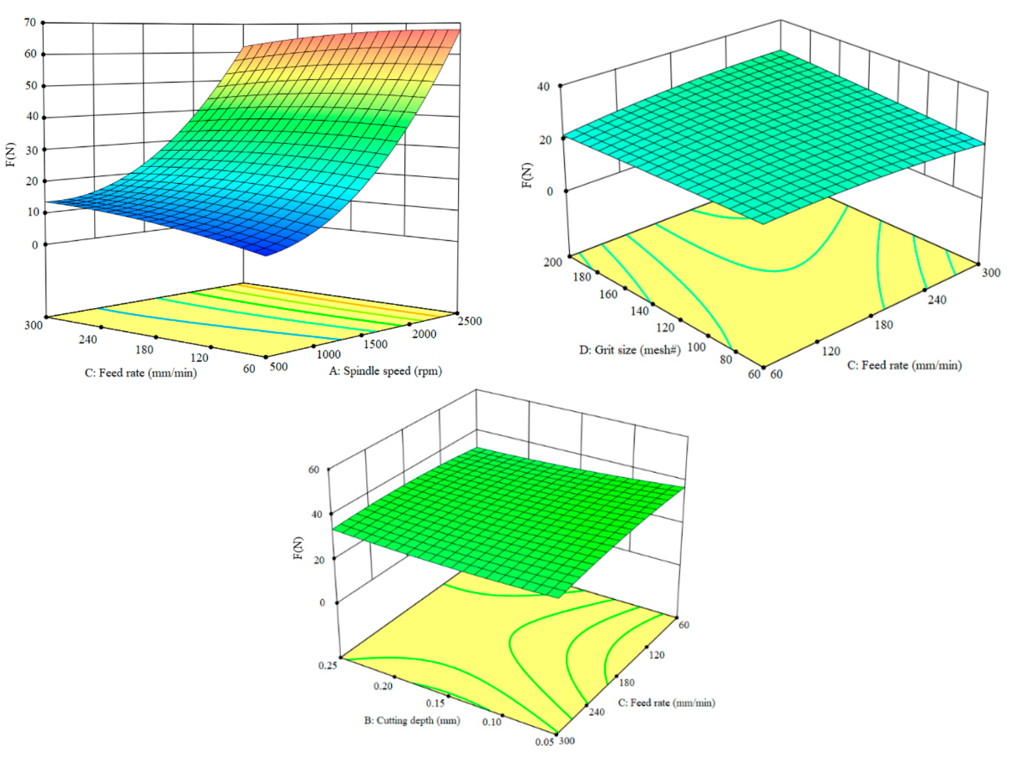
Figure 6.
Normal probability plot for surface roughness.

Figure 7.
Two variable interactive effects of spindle speed, cutting depth, feed rate, and grit size on surface roughness.
Figure 7.
Two variable interactive effects of spindle speed, cutting depth, feed rate, and grit size on surface roughness.
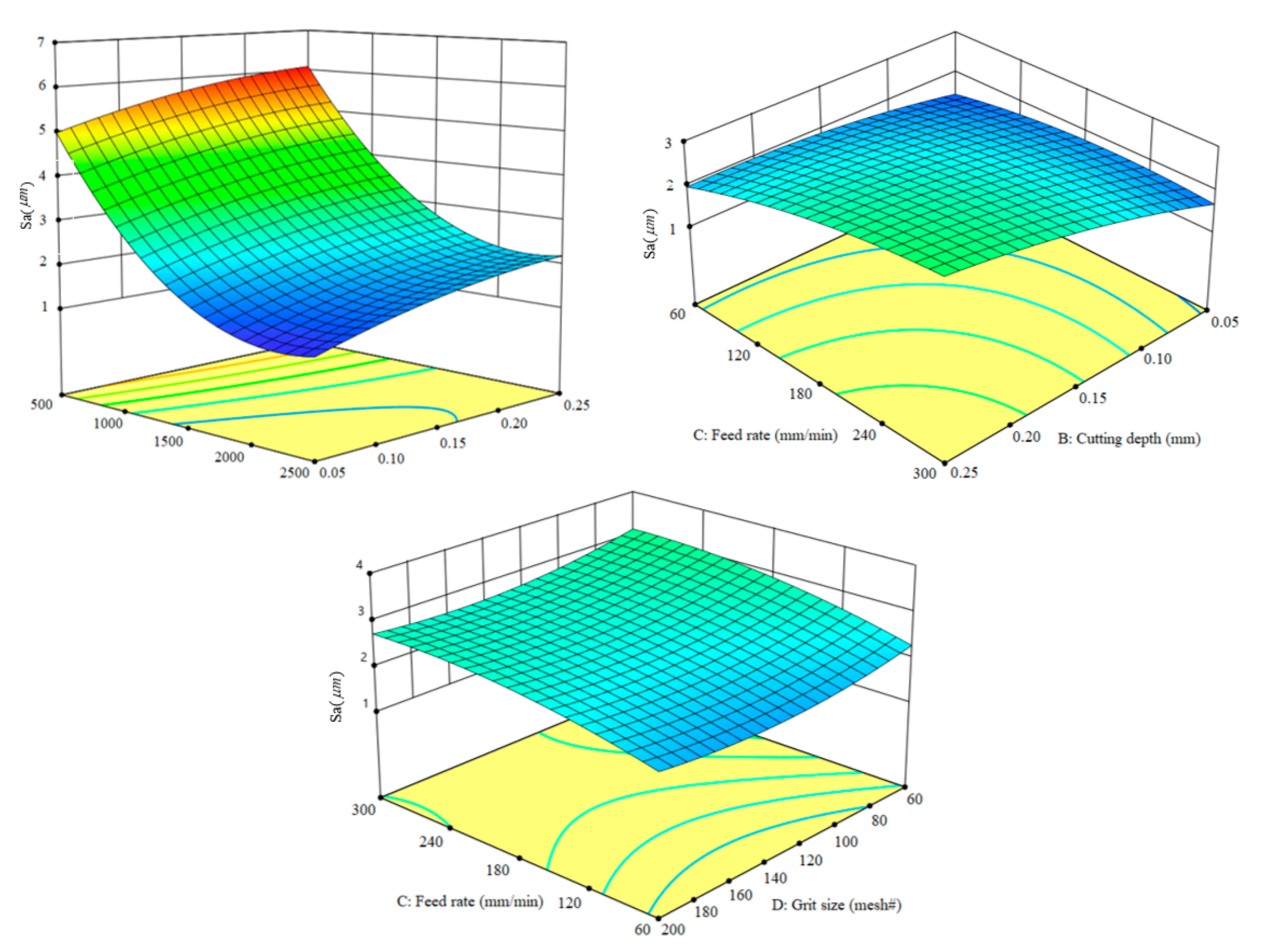
Figure 8.
Result of Pareto optimal solution set.

Table 1.
Model characteristics of the grinding unit.
| Tool No. | Grit Size (mesh #) | Diameter of the Tool Shank | ) | Wheel Diameter D (mm) |
|---|---|---|---|---|
| 1 | 60# | 6 | 88 | 8 |
| 2 | 100# | 6 | 41 | 8 |
| 3 | 120# | 6 | 30 | 8 |
| 4 | 150# | 6 | 40 | 8 |
| 5 | 200# | 6 | 20 | 8 |
Table 2.
Material Properties of Workpiece.
| Fiber Orientations | Fiber Diameter | Layer Thickness | Tensile Strength | Elastic Modulus | Density |
|---|---|---|---|---|---|
| 0°/90° | 6~8 μm | 125 μm | 3500 MPa | 235 GPa | 1.78 g/cm3 |
Table 3.
L&T ultrasonic vibration face grinding parameters with their levels.
| Parameters (Code Unit) | −1 | 0 | 1 |
|---|---|---|---|
| Spindle speed (rpm) | 500 | 1500 | 2500 |
| Cutting depth (mm) | 0.05 | 0.15 | 0.25 |
| Feed rate (mm/min) | 60 | 180 | 300 |
| Grit size (mesh#) | 60 | 120 | 300 |
Table 4.
Model characteristics of the grinding unit.
| Run Order | Spindle Speed (rpm) | Cutting Depth (mm) | Feed Rate (mm/min) | Grit Size (mesh#) | Grinding Force F (N) | ) |
|---|---|---|---|---|---|---|
| 1 | 2500 | 0.15 | 60 | 120 | 68.4 | 1.43 |
| 2 | 2500 | 0.05 | 180 | 120 | 68.6 | 1.13 |
| 3 | 1500 | 0.15 | 180 | 120 | 25.4 | 2.55 |
| 4 | 1500 | 0.05 | 180 | 60 | 27 | 2.1 |
| 5 | 1500 | 0.15 | 300 | 60 | 20.1 | 3.16 |
| 6 | 1500 | 0.25 | 60 | 120 | 21.8 | 2.02 |
| 7 | 500 | 0.15 | 60 | 120 | 4.1 | 4.94 |
| 8 | 1500 | 0.15 | 60 | 60 | 24.9 | 2.28 |
| 9 | 2500 | 0.25 | 180 | 120 | 66.1 | 2.23 |
| 10 | 1500 | 0.15 | 180 | 120 | 25.4 | 2.55 |
| 11 | 1500 | 0.15 | 300 | 200 | 27.2 | 2.74 |
| 12 | 1500 | 0.05 | 180 | 200 | 28.9 | 2.02 |
| 13 | 1500 | 0.15 | 60 | 200 | 21.7 | 2.04 |
| 14 | 1500 | 0.25 | 180 | 60 | 24.4 | 3.42 |
| 15 | 500 | 0.15 | 300 | 120 | 13.3 | 6.12 |
| 16 | 1500 | 0.15 | 180 | 120 | 25.4 | 2.55 |
| 17 | 1500 | 0.05 | 300 | 120 | 24.7 | 1.7 |
| 18 | 2500 | 0.15 | 180 | 60 | 67.2 | 2.25 |
| 19 | 1500 | 0.15 | 180 | 120 | 25.4 | 2.55 |
| 20 | 2500 | 0.15 | 180 | 200 | 65.2 | 1.97 |
| 21 | 500 | 0.15 | 180 | 60 | 7.7 | 6.18 |
| 22 | 1500 | 0.25 | 180 | 200 | 26.3 | 2.85 |
| 23 | 500 | 0.15 | 180 | 200 | 13.6 | 5.81 |
| 24 | 1500 | 0.15 | 180 | 120 | 25.4 | 2.55 |
| 25 | 1500 | 0.05 | 60 | 120 | 27.2 | 1.44 |
| 26 | 500 | 0.05 | 180 | 120 | 13.2 | 5 |
| 27 | 500 | 0.25 | 180 | 120 | 10.6 | 6.14 |
| 28 | 2500 | 0.15 | 300 | 120 | 63.2 | 1.84 |
| 29 | 1500 | 0.15 | 180 | 120 | 25.4 | 2.55 |
| 30 | 1500 | 0.25 | 300 | 120 | 25 | 3.35 |
Table 5.
ANOVA for grinding force.
| Source | Sum of Squares | DF | Mean Square | F-Value | p-Value |
|---|---|---|---|---|---|
| Model | 10,867.88 | 14 | 776.28 | 2240.03 | <0.0001 |
| A-Spindle speed | 9049.73 | 1 | 9049.73 | 26,113.91 | <0.0001 |
| B-Cutting depth | 19.25 | 1 | 19.25 | 55.56 | <0.0001 |
| C-Feed rate | 5.54 | 1 | 5.54 | 15.97 | 0.0012 |
| D-Grit size | 11.21 | 1 | 11.21 | 32.36 | <0.0001 |
| AC | 51.84 | 1 | 51.84 | 149.59 | <0.0001 |
| AD | 15.94 | 1 | 15.94 | 45.98 | <0.0001 |
| BC | 8.12 | 1 | 8.12 | 23.44 | 0.0002 |
| CD | 25.37 | 1 | 25.37 | 73.22 | <0.0001 |
| A² | 1206.89 | 1 | 1206.89 | 3482.60 | <0.0001 |
| B² | 8.17 | 1 | 8.17 | 23.58 | 0.0002 |
| C² | 19.43 | 1 | 19.43 | 56.07 | <0.0001 |
| Residual | 5.20 | 15 | 0.3465 | ||
| Lack of Fit | 5.20 | 10 | 0.5198 | ||
| Pure Error | 0.0000 | 5 | 0.0000 | ||
| Cor Total | 10,873.08 | 29 |
Table 6.
ANOVA for surface roughness.
| Source | Sum of Squares | DF | Mean Square | F-Value | p-Value |
|---|---|---|---|---|---|
| Model | 64.80 | 14 | 4.63 | 5.785 × 10⁵ | <0.0001 |
| A-Spindle speed | 44.11 | 1 | 44.11 | 5.513 × 10⁶ | <0.0001 |
| B-Cutting depth | 3.41 | 1 | 3.41 | 4.258 × 10⁵ | <0.0001 |
| C-Feed rate | 1.80 | 1 | 1.80 | 2.249 × 10⁵ | <0.0001 |
| D-Grit size | 0.3201 | 1 | 0.3201 | 40,009.21 | <0.0001 |
| AB | 0.0004 | 1 | 0.0004 | 49.99 | <0.0001 |
| AC | 0.1482 | 1 | 0.1482 | 18,524.67 | <0.0001 |
| AD | 0.0021 | 1 | 0.0021 | 257.67 | <0.0001 |
| BC | 0.2862 | 1 | 0.2862 | 35,771.46 | <0.0001 |
| BD | 0.0612 | 1 | 0.0612 | 7647.60 | <0.0001 |
| CD | 0.0081 | 1 | 0.0081 | 1009.32 | <0.0001 |
| A² | 10.97 | 1 | 10.97 | 1.371 × 10⁶ | <0.0001 |
| B² | 0.2475 | 1 | 0.2475 | 30,937.09 | <0.0001 |
| C² | 0.3707 | 1 | 0.3707 | 46,325.29 | <0.0001 |
| D² | 0.4611 | 1 | 0.4611 | 57,631.92 | <0.0001 |
| Residual | 0.0001 | 15 | 8.001 × 10⁻⁶ | ||
| Lack of Fit | 0.0001 | 10 | 0.0000 | ||
| Pure Error | 0.0000 | 5 | 0.0000 | ||
| Cor Total | 64.80 | 29 |
Table 7.
Some Pareto optimal solutions for optimization.
| Run Order | Spindle Speed (rpm) | Cutting Depth (mm) | Feed Rate (mm/min) | Grit Size (mesh#) | Grinding Force F (N) | ) |
|---|---|---|---|---|---|---|
| Center point level | 1500 | 0.15 | 180 | 120 | 25.4 | 2.55 |
| 1 | 1600 | 0.055 | 60 | 80 | 47.868 | 1.527 |
| 2 | 1360 | 0.055 | 60 | 80 | 39.673 | 1.960 |
| 3 | 1600 | 0.055 | 60 | 100 | 50.870 | 1.460 |
| 4 | 1360 | 0.055 | 60 | 60 | 36.536 | 2.071 |
| 5 | 1220 | 0.055 | 60 | 60 | 32.369 | 2.392 |
| 6 | 1280 | 0.055 | 60 | 70 | 35.683 | 2.188 |
| 7 | 1220 | 0.055 | 60 | 70 | 33.976 | 2.331 |
| 8 | 1500 | 0.055 | 60 | 80 | 44.271 | 1.690 |
| 9 | 1600 | 0.055 | 60 | 60 | 44.866 | 1.636 |
| 10 | 1500 | 0.055 | 60 | 60 | 41.213 | 1.800 |
| 11 | 1120 | 0.055 | 60 | 70 | 31.340 | 2.591 |
| 12 | 1810 | 0.055 | 60 | 60 | 53.383 | 1.374 |
| 13 | 1500 | 0.055 | 60 | 60 | 41.213 | 1.800 |
| 14 | 1120 | 0.055 | 60 | 70 | 31.340 | 2.591 |
Disclaimer/Publisher’s Note: The statements, opinions and data contained in all publications are solely those of the individual author(s) and contributor(s) and not of MDPI and/or the editor(s). MDPI and/or the editor(s) disclaim responsibility for any injury to people or property resulting from any ideas, methods, instructions or products referred to in the content. |
© 2023 by the authors. Licensee MDPI, Basel, Switzerland. This article is an open access article distributed under the terms and conditions of the Creative Commons Attribution (CC BY) license (https://creativecommons.org/licenses/by/4.0/).
Share and Cite
MDPI and ACS Style
Liu, S.; Zheng, K.; Li, H.; Cao, Z.; Zhao, S. Multi-Objective Optimization of Process Parameters in Longitudinal-Torsional Ultrasonic Vibration Face Grinding CFRP. Machines 2023, 11, 935. https://doi.org/10.3390/machines11100935
AMA Style
Liu S, Zheng K, Li H, Cao Z, Zhao S. Multi-Objective Optimization of Process Parameters in Longitudinal-Torsional Ultrasonic Vibration Face Grinding CFRP. Machines. 2023; 11(10):935. https://doi.org/10.3390/machines11100935
Chicago/Turabian StyleLiu, Shuliang, Kai Zheng, Hongcheng Li, Zhengfeng Cao, and Shuang Zhao. 2023. "Multi-Objective Optimization of Process Parameters in Longitudinal-Torsional Ultrasonic Vibration Face Grinding CFRP" Machines 11, no. 10: 935. https://doi.org/10.3390/machines11100935
Note that from the first issue of 2016, this journal uses article numbers instead of page numbers. See further details here.