
Modeling the Contact Force in Constrained Human–Robot Collisions

Robotic Systems, Fraunhofer IFF, Sandtorstr. 22, 39106 Magdeburg, Germany
*
Author to whom correspondence should be addressed.
Machines 2023, 11(10), 955; https://doi.org/10.3390/machines11100955
Submission received: 11 July 2023
/
Revised: 6 October 2023
/
Accepted: 10 October 2023
/
Published: 12 October 2023
(This article belongs to the Special Issue Assessment, Validation and Improvement of Safety and Ergonomics in Human-Robot Interaction)
Abstract
:Collaborative robots (cobots) become more and more important in industrial manufacturing as flexible companions, working side by side with humans without safety fences. A key challenge of such workplaces is to guarantee the safety of the human co-workers. The safeguarding Power and Force Limiting, as specified by ISO 10218-2 and ISO/TS 15066, has the objective to protect humans against robot collisions by preventing the robot from exceeding biomechanical limits. Unintended contact such as collisions can occur under unconstrained spatial conditions (a human body part can move freely) or constrained spatial conditions (a human body part is pinched). In particular, collisions under constrained conditions involve a high risk of injury and thus require the robot to stop immediately after detecting the collision. The robot’s speed has a significant influence on its stopping behavior, though, and thus on the maximum collision forces that the robot can exert on the human body. Consequently, a safe velocity is required that avoids the robot from exerting forces and pressures beyond the biomechanical limits. Today, such velocities can only be ascertained in costly robot experiments. In this article, we describe a model that enables us to determine the contact forces of a cobot as they occur in constrained collisions. Through simulations, it becomes possible to iteratively determine the maximum safe velocity for a specific contact hazard that occurs under constrained spatial conditions. Experimental tests with different cobots confirm the results of our model, albeit not for all robots. Despite the mixed test results, we strongly believe that our model can significantly improve the reliability of assumptions made today during the planning of cobots.
1. Introduction
Collaborative robots (cobots) are playing an increasingly important role in the flexible production of tomorrow [1]. Compared to conventional industrial robots, they typically work in a fenceless environment together with humans [2], if the working scenario features collaborative tasks or requires physical interaction. Like other machinery, a risk assessment has to be carried out for cobot applications in order to identify hazards and to take measures that reduce their associated risks to an acceptable level. To reduce the risk of contact-related hazards, such as collisions, today’s cobots are equipped with technology that enable a Power and Force Limiting (PFL) mode as introduced in ISO 10218-2 [3] and further specified in ISO/TS 15066 [4]. The PFL mode ensures that the cobot does not exceed the biomechanical limit values listed in ISO/TS 15066 when being in physical contact with humas [5]. This ability is typically realized by safety-rated functions that monitor the force and/or torque [6,7], paired with functions that limit the maximum speed [8,9]. The force and/or torque monitoring function is intended to detect collisions and to stop the robot immediately. In practice, it is advisable to set the threshold value for the force and/or torque monitoring to the smallest possible value at which the application is still robust. The lower limit is typically dependent on external process forces and the available range in which the threshold can be varied. By limiting a robot’s velocity, the kinetic energy that is accumulated by the robot structure can be reduced and so can the braking distance after an emergency stop is initiated. Since a typical robot programmer’s intention is to minimize process times, it turns out to be ideal to increase the velocity threshold to the point at which the robot is still not exceeding the biomechanical limits.
Today, the maximum safe velocity is determined in robot collision tests with a biofidel measuring device [10]. The device measures collision forces and pressures that can be compared to the limits. It utilizes a spring-damper combination to replicate the biomechanics of the human body part under test [11]. The collision test and therefore the approach to determine safe velocities are considerably time-consuming since the tests have to be performed separately for every robot movement and body location at risk.
In the past, several studies have been conducted to improve the measurement procedure. For instance, Kovincic et al. [12] propose “a boosted decision tree”, which uses a set of executed measurements in different robot postures and biofidelic configurations to interpolate collision forces for postures in-between. This approach significantly reduces the number of tests compared to the individually performed collision tests but does not eliminate the collision tests. Scibilia et al. [13] have shown that experimental collision measurements are generally quite sensitive to the measurement device and test setup. As an alternative, they suggest the use of various model-based approaches to predict a robot’s collision behavior [14,15,16]. Jeanneau et al. [17] present a method to simulate a compliant robot’s behavior in collisions. Seriani et al. [18] show that compliant mechanisms can be beneficial as they reduce a robot’s overall stiffness and thus the maximum force in collisions. Most of the models researched focus on the exchange of kinetic energy between the colliding masses and thus are ideally suited to predict the contact force in unconstrained collisions, where the influence of the motion controller and safety functions can be ignored due to the short contact duration [19].
In the event of pinching (i.e., constrained collisions at low impact velocities), the exchange of kinetic energy and inertial effects are less relevant to the contact forces. Haddadin et al. [20] showed that in pinching contacts, the contact force significantly depends on the nominal torques of the joints and their ability to detect collisions. Hence, a robot’s collision management procedure, which entails collision detection, control (e.g., impedance control vs. speed control), and braking maneuvers, has a great effect on the maximum contact force [8].
To predict the contact forces in pinching contacts, this article presents a new model. The model takes a robot’s safety configuration and its braking characteristics as well as the contact stiffness at the collision point into account. This paper first introduces assumptions that we have made for the model. Next, we describe the model’s parameterization that includes braking parameters in particular. Lastly, pinching tests with two commercially available cobots (KUKA iiwa 14 and Universal Robots UR10e) and the results obtained from the tests are presented and then compared to our model’s predictions.
2. Pinching Model
2.1. Generalized Collision Behavior
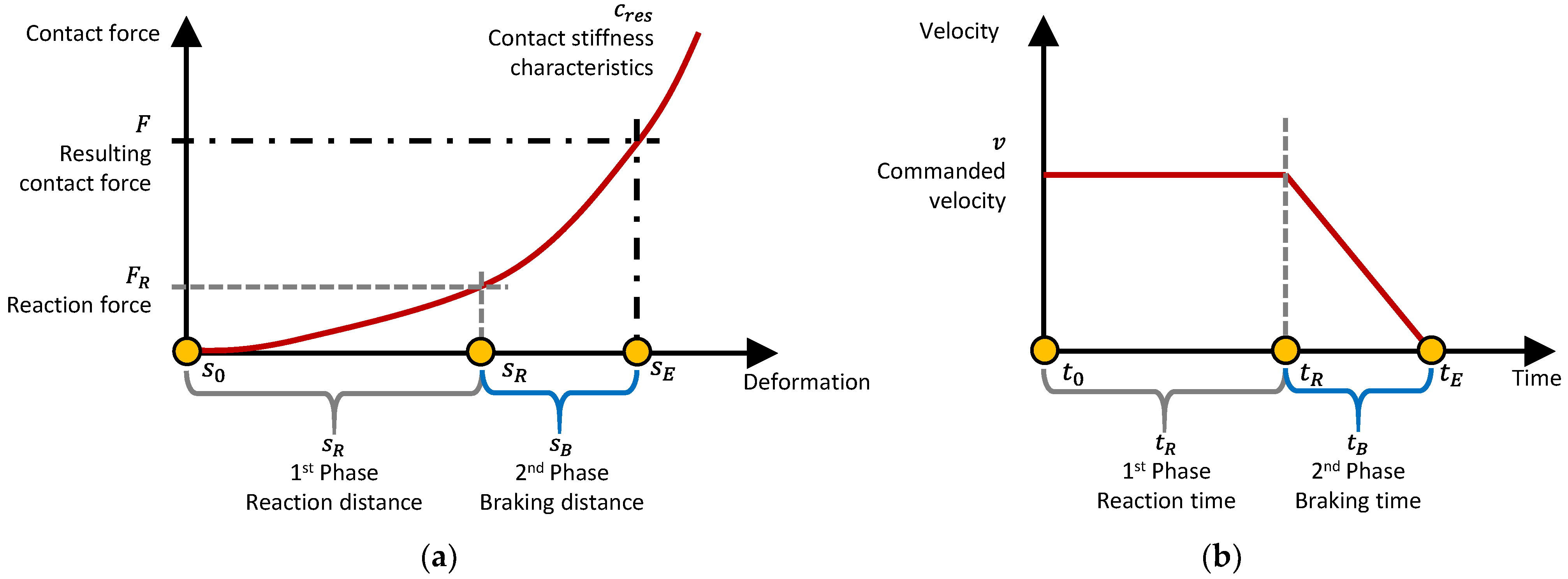
During pinching contacts, the human body part is trapped between the robot and the environment. The contact force increases as the robot breaks. The magnitude of the force depends on the penetration depth and the stiffness characteristic at the contact point, given by the stiffness of the human body part and the stiffness of the robot structure. Typical cobots show a collision behavior that can be divided into two phases:
- First Phase: Reaction distance. At initial contact, the force rises while the robot motion controller compensates the velocity error caused by the external forces. As long as the force or torque thresholds monitored by the robot’s safety controller are not exceeded, the controller continues to compensate, as illustrated in Figure 1b.
- Second Phase: Braking distance. As soon as the robot detects an exceedance of the force or torque threshold, it immediately initiates an emergency stop. Typical motion controllers are configured to fulfill a braking maneuver of category 1 (S1). Such a maneuver is characterized by asynchronous and maximum deceleration of each joint drive. The path of the contact point during the braking determines the maximum contact force. Based on the first assumption that the robot holds its velocity, the velocity before the braking starts can be assumed to be equal to the commanded velocity.
2.2. Model Description
Given both phases, it is possible to predict the maximum contact force of a pinching contact by using the force-deformation curve at the collision point and the robot’s reaction distance and braking distance .
Figure 1a illustrates a typical deformation of the contact point during the contact. The force-deformation curve includes the stiffness of the human soft tissue and the stiffness of the cobot’s surface at the collision point, where denotes the deformation. For cobots with electrical drives and a stiff frame, holds and further leads to . Alternatively, Vemula et al. [21] describe an FE simulation approach to calculate for arbitrary stiffness and impact shape combinations. Characteristic force-deformation curves are given by Behrens and Zimmermann [22].
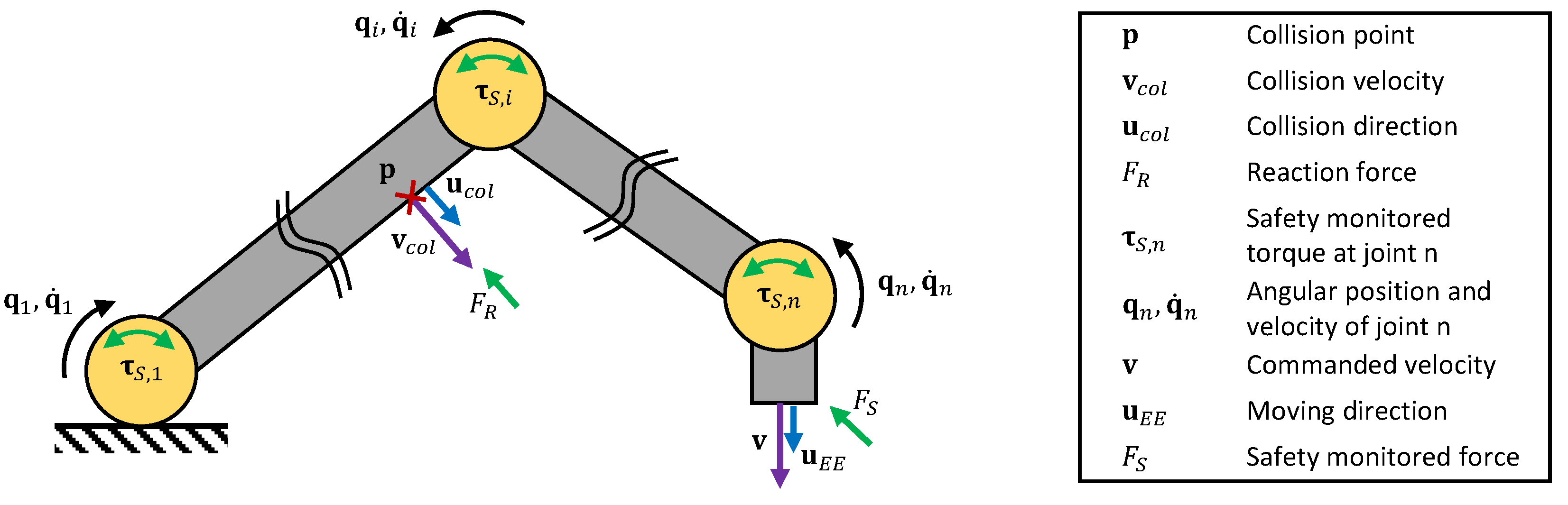
Figure 2 introduces all relevant robot states that are required to determine the reaction force that and then from the force-deformation curve (see Figure 1a). If the contact point on the robot is the Tool Center Point (TCP), equals the safety monitored force . Otherwise must be calculated, for instance, with the Jacobian matrix for the point under consideration. Then, it will be necessary to align the collision force to the collision direction as follows:
Based on and the translatory part of the Jacobian for the collision point (with being the number of joints), the corresponding torque can be calculated by
with and , we receive the force at the TCP :
Based on , , and , we finally come to an expression to calculate the reaction force for the contact point,
which is simply the ratio of the different forces. If the robot monitors joint torques (rather than forces), the reaction force can be calculated by
From the contact point’s force-deformation curve, the deformation depth can be determined for . Next, the angular position at which braking is initialized has to be identified. Let be the position of the collision point, it can be simply calculated from using forward kinematics. Then, must also lead to as follows:
The associated joint velocities
are calculated using the Jacobian for the TCP and the commanded velocity . Once the robot’s safety controller detects a violation of the torque or force thresholds, it immediately initiates an emergency stop. A typical emergency stop decelerates the drives as fast as possible without holding the robot on its commanded trajectory. Since the robot braking characteristics depend on several parameters, such as mechanical structure, drive type, stopping strategy, and control behavior, there is no general braking model that can be used to predict braking distances and times. Our model uses, therefore, a dataset of experimentally obtained braking data,
with providing the braking distance for each drive as a function of joint velocity , payload , and extension . Note that depends on the joint configuration , which is defined in the range of . The braking distance is then given for a certain set of , , and . After the robot has stopped, the final joint position is then given by
With , the cartesian position can be calculated using forward kinematics. This position ultimately leads to the deformation value:
The corresponding contact force is then given by
2.3. Model Parameterization
The key component of our model is the dataset which delivers a robot’s braking distances. Manufacturers often provide such datasets, at least for a limited number of axes (in the case of a 6 DoF robot with , the first three axes [23], and in the case of a 7 DoF robot with , the first four axes [24])). The given parameters are often poorly resolved and limited to certain extensions, payloads, and joint velocities. In order to increase the model accuracy, it is therefore recommended to use a dataset with higher resolution which covers all axes without range limitations. For our model, we performed braking tests with two cobots. From the test results, we derived the dataset to use for the model presented here (see Section 4.1).
3. Experiments
3.1. Setup
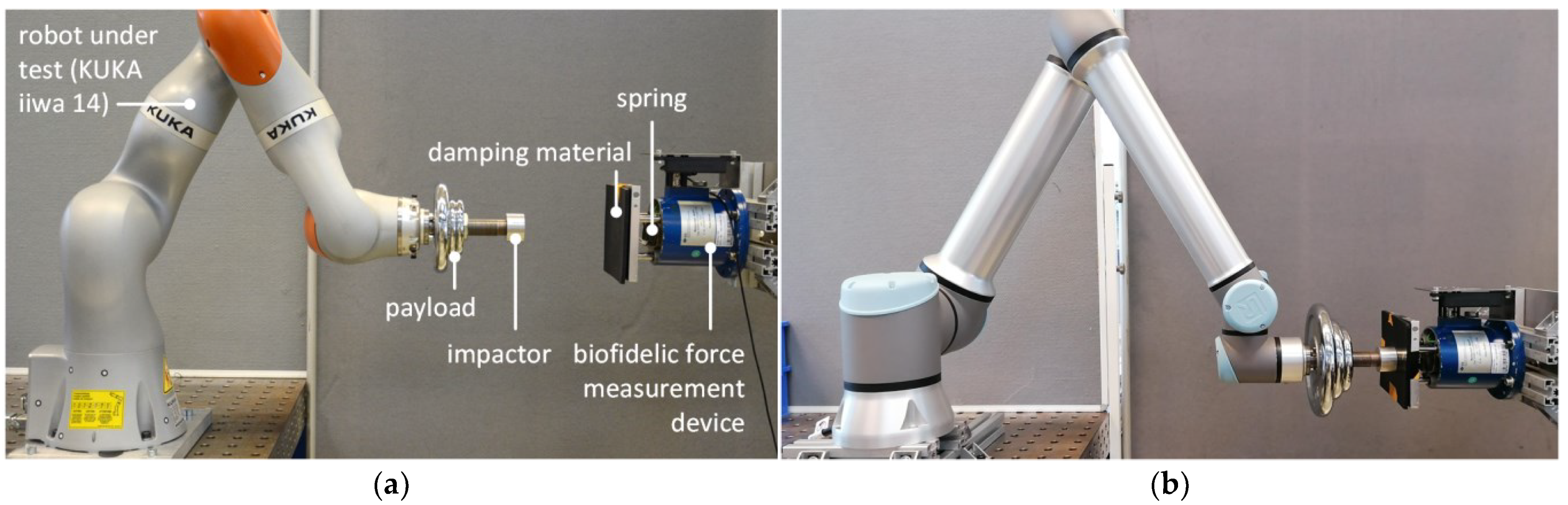
The experiments had the objective to evaluate our model’s predictions based on results from pinching tests with two different cobots, namely KUKA iiwa 14 and Universal Robots UR10e. Figure 3 illustrates the experimental setup for both robots. The robot under test was equipped with an impactor and varying payloads. During the test, the robot was commanded to collide with a biofidelic measurement device. The movement sequences were programmed on the robot’s teach pendant and executed by the standard robot controller that provides various safety functions such as force and torque monitoring. The robot states were sampled by the cobots internal data recorder at for the KUKA iiwa 14 and at for the Universal Robots UR10e. The measuring device [10] measured the contact forces at a sample rate of in a calibrated range of .
To replicate the contact behavior of human soft tissue, the measuring device was equipped with particular combinations of springs and foam materials. In our experiments, we used a “soft” combination (spring rate ; foam material with shore hardness 10; representing abdomen) and a “stiff” combination (spring rate ; foam material with shore hardness 70; representing fingers) [11]. In the experiments, the robot under test was commanded to perform a linear movement in the horizontal plane in the direction of the measuring device. The trajectory ensures that the robot moved at constant speed when it collided. The impact velocity was varied in a wide range of . Additionally, we tested the robot with several payloads. Every experimental condition was repeated five times. The tool weight and inertia were correctly configured in the safety configuration of the robot’s control unit. The monitored force threshold for the TCP was set to a constant value. Once the robot exceeded the force threshold, it was commanded to perform a stop of category S1 as described above.
3.2. Results
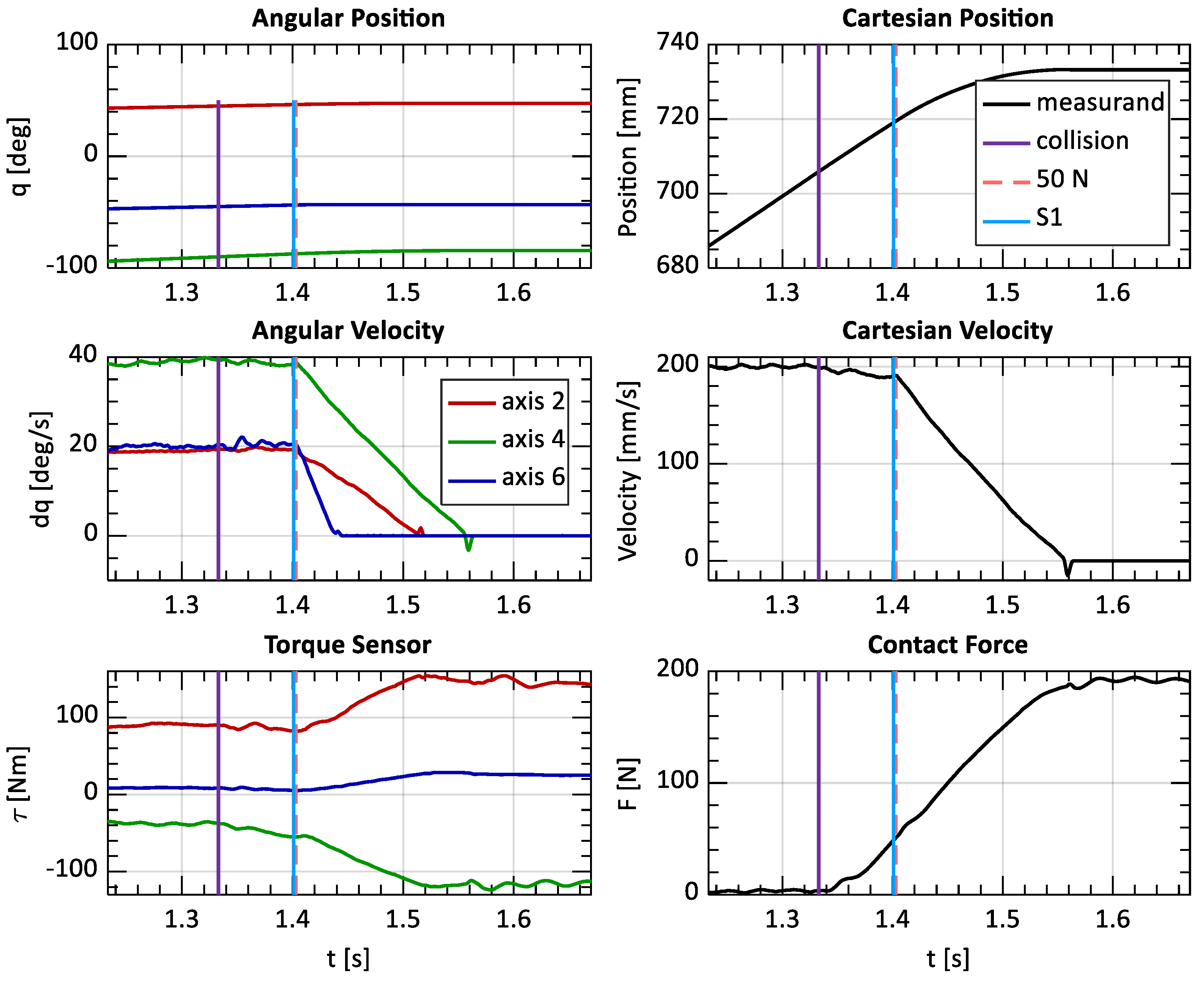
The robots’ behavior observed in the experiments can be described based on the measurements taken. Figure 4 displays the time-resolved robot states recorded for a test at . The vertical lines indicate different events. The purple line marks the beginning of the contact, the blue line marks the initiation of the emergency stop, and the red dashed line marks the point at which was reached. The joint angles and velocities are only plotted for the second, fourth, and sixth axis since the others have not moved during the linear movement. The joint and cartesian velocity (in impact direction) indicate that the velocities slightly decrease after initial contact. After the robot’s safety unit has initiated an emergency stop, the motion controller immediately decelerates all joint drives to zero velocity, as expected. According to the specification of an S1 emergency stop, each axis stops as fast as possible without any synchronization (axis 2 and 4 after and axis 6 after 20 ms). While the robot is in contact with the measuring device, the contact force increases until all axes have finally stopped. Once the braking maneuver is completed and the mechanical brakes are initiated, the contact force remains at a constant maximum.
4. Discussion
4.1. Comparison of the Model with the Experimental Results
A comparison of the pinching model with the experimental results should reveal the model’s accuracy in predicting maximum pinching forces. Before the model was used in a simulation, the overall stiffness of the measuring device was recorded using an algometer in combination with the impactor used later in the experiments. The force-deformation curves from these indentation tests were then used as force-deformation curves from which the model could determine the reaction force for a given reaction distance and the maximum contact force for a given maximum deformation .
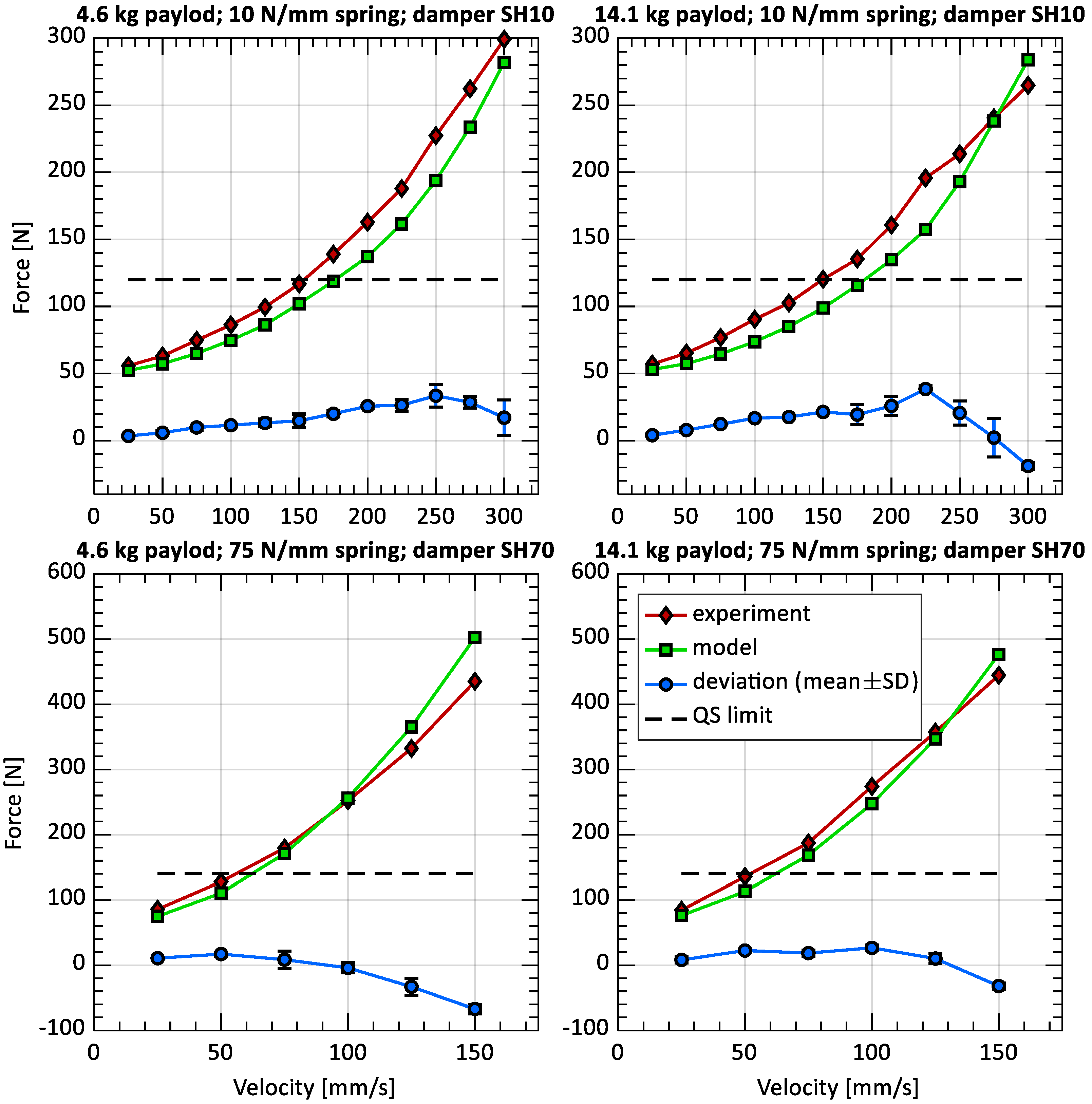
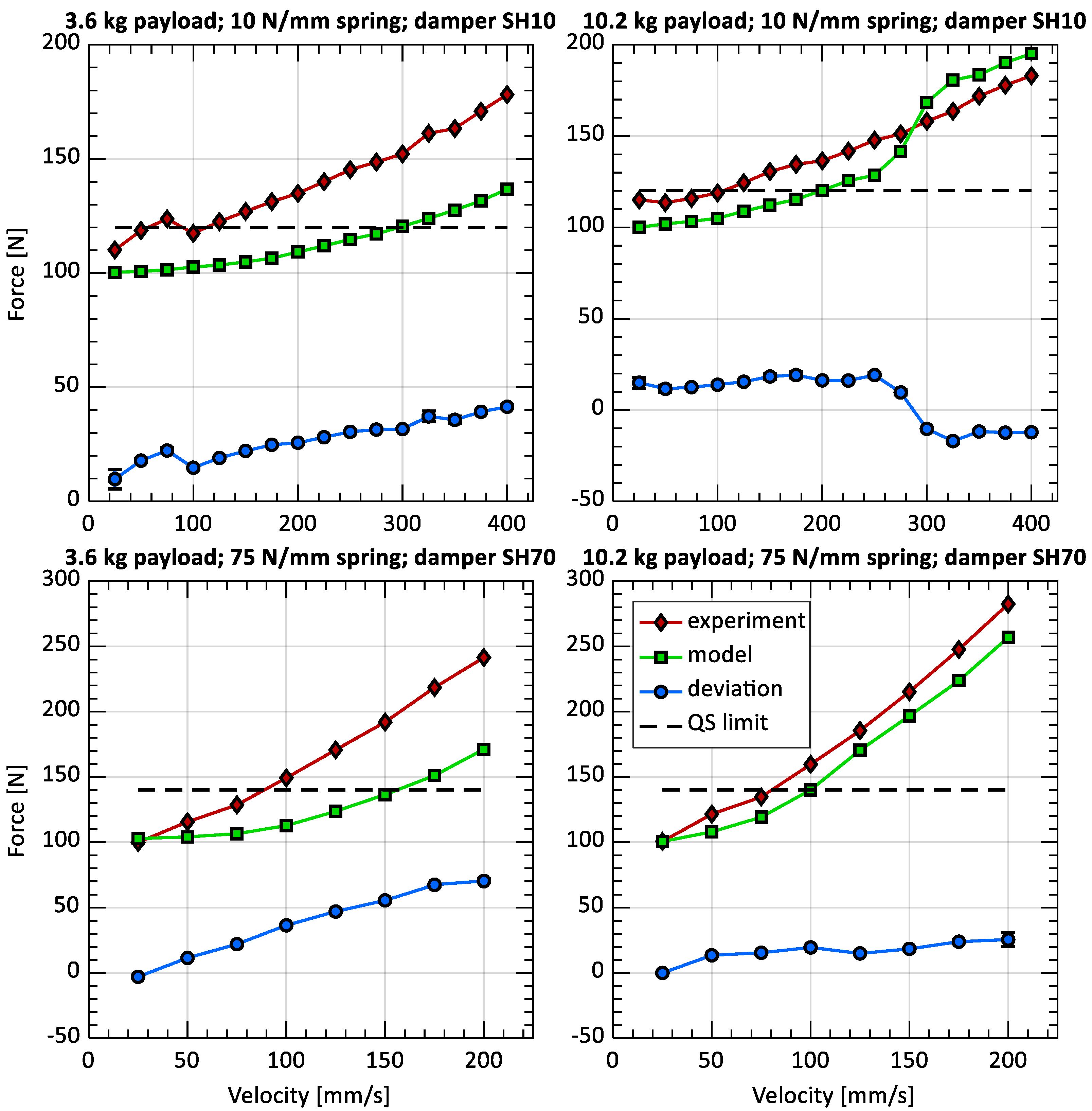
Figure 5 and Figure 6 illustrate the maximum contact force at different impact velocities and for different payloads, each for the soft and stiff configurations of the measuring device. The red diamonds represent the maximum contact force measured. The green squares are our model’s output. The black dashed horizontal lines mark the quasi-static (QS) limit as listed in ISO/TS 15066 [4] for abdomen ( and fingers (. The blue circles indicate the average difference between the maximum contact force calculated with the model and the force measured in the experiments. A negative difference means that the model delivers higher and thus more conservative results.
The results for the KUKA iiwa 14 are shown in Figure 5. For the soft combination (spring rate , foam material SH10), the model tends to predict lower contact forces. For the stiff combination (spring rate , foam material SH70), the model’s output matches the maximum forces measured at higher velocities well. Across all velocities, the difference between the model and the experiment is (mean ± standard deviation).
Figure 6 shows the model-based and experimentally acquired forces for the tests with UR10e. It can be seen that the values predicted have less accuracy compared to the tests with KUKA iiwa 14. The overall difference between the model and the experiment is .
4.2. Model Accuracy
The comparison reveals an acceptable accuracy. However, the question arises as to whether the model is reliable enough to replace collision tests. The following section analyzes various factors, namely reaction distance and braking distance , which both have a strong influence on our model’s accuracy.
4.2.1. Reaction Distance
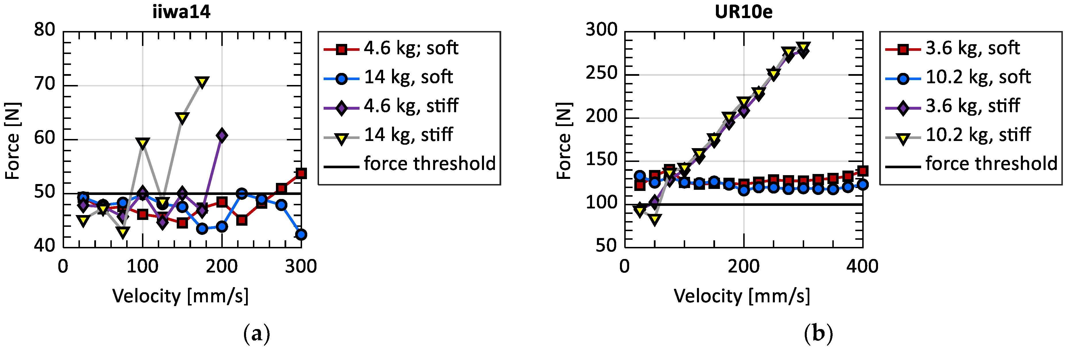
As introduced above, the reaction distance corresponds to the reaction force at which the robot detects the contact and then immediately initiates an emergency stop. Its value is given by the force-deformation curve that represents the overall stiffness of the contact. The model assumes that the emergency stop is initiated promptly once the force threshold set in the safety settings is exceeded. If the robot initiates the stop a moment earlier, the model will predict a larger and thus more conservative reaction distance.
For KUKA iiwa 14 (see Figure 7a), the force threshold was set to As the measurement results clearly indicate, the robot is able to initiate the emergency stop at (mean ± SD). High deviations occur only in some tests with the stiff measuring device.
The results for Universal Robots UR10e draw a different picture (see Figure 7b). Here, the safety force threshold was set to . However, the force at which the robot has finally initiated an emergency stop varies within a significantly wider range. For the soft measuring device, the emergency stop is initiated at a contact force between and . For the stiff combination, the force increases as the velocity increases. This ultimately leads to trigger forces that vary in a large range of (mean ± SD). A direct consequence of this is that our model underestimates the reaction distance .
4.2.2. Braking Distance
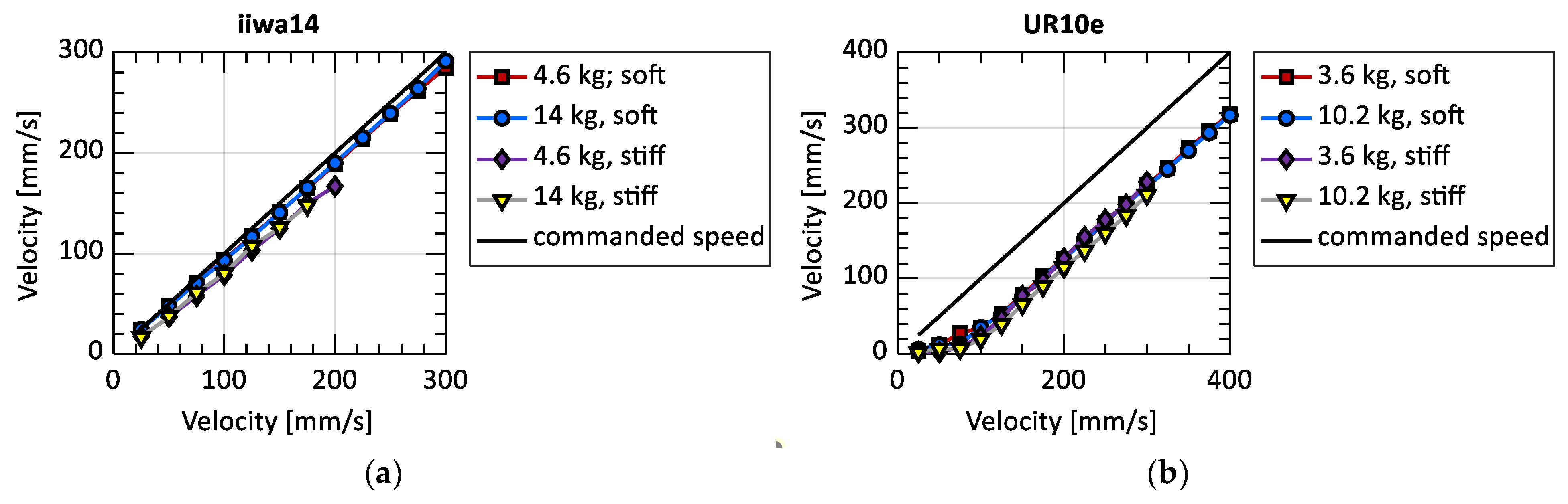
The second factor is the braking distance . The model uses the commanded joint velocity, the payload, and the extension of the cobot to calculate the braking distance of each joint. The braking distance in collision direction is calculated using forward kinematics. The extension and payload of the robot are known at the time when the emergency stop is initiated. However, the velocity must be further examined. The model uses the commanded joint velocity to interpolate the braking distance of each joint since it assumes that the motion controller is able to fully compensate velocity errors before is reached. Figure 8 compares the commanded velocity of the robot tested with the velocity measured the moment before the robot has initiated the emergency stop.
For KUKA iiwa 14, the velocity has slightly decreased during the reaction phase. The overall relative error between commanded and actual velocity is (mean ± SD). The error made with our model’s assumption is considered small and thus neglectable for KUKA iiwa 14.
Unlike KUKA iiwa 14, Universal Robots UR10e has a significantly reduced velocity when the robot initiates the emergency stop. Especially for low velocities and the soft measuring device, the velocity error is up to . For some tests with the stiff combination, the velocity surprisingly reduced to zero. The overall relative velocity error is (mean ± SD). The significant velocity error before the emergency stop was initiated leads to an overestimation of the braking distance by the model and thus to higher estimates of the contact force.
5. Conclusions
In this article, we have presented a new method to determine the maximum force in pinching contacts. For the model, we have made different simplifications of the contact mechanics. Additionally, our model relies on data to take the robot’s braking characteristics and the overall contact stiffness into account.
We have performed pinching experiments with two different robots in order to evaluate our model’s accuracy. Both robots were tested with different payloads and stiffness configurations for the measuring device. The comparison of the maximum forces from the tests and those predicted by our model have shown that the accuracy depends on the robots control behavior. For the KUKA iiwa 14, the model is able to predict forces that match the experimental results well. As expected, and assumed for our model, the robot seems to be able to precisely trigger the emergency stop at the defined threshold. Moreover, the motion controller seems to be able to compensate for velocity errors as caused by contact forces.
For the Universal Robots UR10e, our model has less accuracy since our assumptions do not apply to this specific robot type. In most cases, the robot tends to initiate the emergency stop clearly after the contact force has exceeded the force threshold set in the safety configuration. Additionally, the robot loses velocity before the emergency stop is triggered. Interestingly, both observations have oppositional effects in the model, which elusively improves the model’s prediction accuracy.
The experiments revealed that our model’s ability to estimate pinching forces significantly depends on the control behavior of the robot under consideration. In the experiments, the quasi-static limit value was well met at relatively low velocities (). It seems that lower velocity buys the robot controller sufficient time to detect and manage pinching contacts. Both robots have shown different collision management strategies in our experiments that have to be further elaborated for our model. The use of our model is therefore only advisable if the robot considered has a collision management behavior that applies to the assumptions we have made at the beginning. Our further research will focus on model improvements that take a robot’s control behavior more comprehensively into account. Additionally, further cobots will be tested.
6. Patents
Based on this article, a patent with title “Predefining a maximum permissible speed of a robotic device” was granted by the German Patent and Trademark Office. The patent is registered under reference number DE102021208576B3.
Author Contributions
Conceptualization, S.H. and R.B.; methodology, S.H.; formal analysis, S.H.; experiments, S.H.; resources, R.B.; writing—original draft preparation, S.H.; writing—review and editing, R.B.; supervision, N.E. All authors have read and agreed to the published version of the manuscript.
Funding
This research received no external funding.
Data Availability Statement
The data presented in this study are available on request from the corresponding author under fair and reasonable terms. The data are not publicly available due to copyrights.
Conflicts of Interest
The authors declare no conflict of interest.
References
- Faber, M.; Bützler, J.; Schlick, C.M. Human-robot Cooperation in Future Production Systems: Analysis of Requirements for Designing an Ergonomic Work System. Procedia Manuf. 2015, 3, 510–517. [Google Scholar] [CrossRef]
- Behrens, R.; Saenz, J.; Vogel, C.; Elkmann, N. Upcoming Technologies and Fundamentals for Safeguarding All Forms of Human-Robot Collaboration. In Proceedings of the 8th International Conference on Safety of Industrial Automated Systems, Königswinter, Germany, 18–20 November 2015. [Google Scholar]
- ISO 10218-2:2011; Robots and Robotic Devices—Safety Requirements for Industrial Robots—Part 2: Robot Systems and Integration. International Organization for Standardization (ISO): Geneva, Switzerland, 2011.
- ISO/TS 15066; Robots and Robotic Devices—Collaborative Robots. International Organization for Standardization (ISO): Geneva, Switzerland, 2016.
- Yamada, Y.; Hirasawa, Y.; Huang, S.; Umetani, Y.; Suita, K. Human-robot contact in the safeguarding space. IEEE/ASME Trans. Mechatron. 1997, 2, 230–236. [Google Scholar] [CrossRef]
- de Luca, A.; Albu-Schaffer, A.; Haddadin, S.; Hirzinger, G. Collision Detection and Safe Reaction with the DLR-III Lightweight Manipulator Arm. In Proceedings of the 2006 IEEE/RSJ International Conference on Intelligent Robots and Systems, Beijing, China, 9–13 October 2006; pp. 1623–1630. [Google Scholar] [CrossRef]
- Lee, S.-D.; Kim, Y.-L.; Song, J.-B. Novel collision detection index based on joint torque sensors for a redundant manipulator. In Proceedings of the 2013 IEEE/RSJ International Conference on Intelligent Robots and Systems, Tokyo, Japan, 3–7 November 2013; pp. 4636–4641. [Google Scholar] [CrossRef]
- Haddadin, S.; Albu-Schaffer, A.; Frommberger, M.; Hirzinger, G. The role of the robot mass and velocity in physical human-robot interaction—Part II: Constrained blunt impacts. In Proceedings of the 2008 IEEE International Conference on Robotics and Automation, Pasadena, CA, USA, 19–23 May 2008; pp. 1339–1345. [Google Scholar] [CrossRef]
- Haddadin, S.; Albu-Schaeffer, A.; Hirzinger, G. The role of the robot mass and velocity in physical human-robot interaction—Part I: Non-constrained blunt impacts. In Proceedings of the 2008 IEEE International Conference on Robotics and Automation, Pasadena, CA, USA, 19–23 May 2008; pp. 1331–1338. [Google Scholar] [CrossRef]
- Huelke, M.; Ottersbach, H.-J. How to approve Collaborating Robots: The IFA force pressure measurement system. In Proceedings of the 7th International Conference on the Safety of Industrial Automated Systems, Montreal, QC, Canada, 11–12 October 2012. [Google Scholar]
- BGHM (Ed.) DGUV-Information—Kollaborierende Robotersysteme: Planung von Anlagen Mit Der Funktion “Leistungs-und Kraftbegrenzung; Deutsche Gesetzliche Unfallversicherung (DGUV): Berlin, Germany, 2017. [Google Scholar]
- Kovincic, N.; Gattringer, H.; Müller, A.; Brandstötter, M. A Boosted Decision Tree Approach for a Safe Human-Robot Collaboration in Quasi-static Impact Situations. In Advances in Service and Industrial Robotics, Proceedings of the 29th (Mechanisms and Machine Science), Beijing, China, 16–17 October 2020; Zeghloul, S., Laribi, M.A., Arevalo, J.S.S., Eds.; Springer: Berlin/Heidelberg, Germany, 2020; pp. 235–244. [Google Scholar]
- Scibilia, A.; Valori, M.; Pedrocchi, N.; Fassi, I.; Herbster, S.; Behrens, R.; Saenz, J.; Magisson, A.; Bidard, C.; Kuhnrich, M.; et al. Analysis of Interlaboratory Safety Related Tests in Power and Force Limited Collaborative Robots. IEEE Access 2021, 9, 80873–80882. [Google Scholar] [CrossRef]
- Bicchi, A.; Tonietti, G. Fast and “Soft-Arm” Tactics. IEEE Robot. Automat. Mag. 2004, 11, 22–33. [Google Scholar] [CrossRef]
- Haddadin, S.; Krieger, K.; Mansfeld, N.; Albu-Schaffer, A. On impact decoupling properties of elastic robots and time optimal velocity maximization on joint level. In Proceedings of the 2012 IEEE/RSJ International Conference on Intelligent Robots and Systems, Vilamoura-Algarve, Portugal, 7–12 October 2012; pp. 5089–5096. [Google Scholar] [CrossRef]
- Herbster, S.; Behrens, R.; Elkmann, N. A New Approach to Estimate the Apparent Mass of Collaborative Robot Manipulators. In Experimental Robotics; Puzo, M., Ed.; Springer International Publishing: Cham, Switzerland, 2021; pp. 211–221. [Google Scholar]
- Jeanneau, G.; Bégoc, V.; Briot, S. A Reduced Mass-Spring-Mass-Model of Compliant Robots Dedicated to the Evaluation of Impact Forces. J. Mech. Robot. 2024, 16, 041012. [Google Scholar] [CrossRef]
- Seriani, S.; Gallina, P.; Scalera, L.; Lughi, V. Development of n-DoF Preloaded Structures for Impact Mitigation in Cobots. J. Mech. Robot. 2018, 10, 051009. [Google Scholar] [CrossRef]
- Herbster, S.; Behrens, R.; Elkmann, N. A New Conversion Method to Evaluate the Hazard Potential of Collaborative Robots in Free Collisions. In Experimental Robotics; Siciliano, B., Laschi, C., Khatib, O., Eds.; Springer International Publishing: Cham, Switzerland, 2021; pp. 222–232. [Google Scholar] [CrossRef]
- Haddadin, S.; Albu-Schäffer, A.; Hirzinger, G. Safe Physical Human-Robot Interaction: Measurements, Analysis and New Insights. In Robotics Research; Springer: Berlin/Heidelberg, Germany, 2011; Volume 66, pp. 395–407. [Google Scholar]
- Vemula, B.R.; Ramteen, M.; Spampinato, G.; Fagerstrom, B. Human-robot impact model: For safety assessment of collaborative robot design. In Proceedings of the 2017 IEEE International Symposium on Robotics and Intelligent Sensors (IRIS), Ottawa, ON, Canada; 2017; pp. 236–242. [Google Scholar] [CrossRef]
- Behrens, R.; Zimmermann, J. Bestimmung Biomechanischer Korridore zur Bewertung von Mechanischen Gefährdungen und Ableitung von Steifigkeitsparametern für Zukünftige Messmittel (= Determination of Biomechanical Corridors for the Evaluation of Mechanical Hazards and Estimation of Stiffness Parameters for Future Measurement Devices = Détermination de Corridors Biomécaniques Destinés à L’évaluation de Risques Mécaniques et à la Déduction de Paramètres de Rigidité de Futurs Instruments de Mesure = Determinación de Corredores Biomecánicos Para la Evaluación de Peligros Mecánicos y la Deducción de Parámetros de Rigidez para Futuros Equipos de Medición) (IFA-Report 2022, 2); Deutsche Gesetzliche Unfallversicherung (DGUV): Berlin, Germany, 2022; Available online: https://publikationen.dguv.de/widgets/pdf/download/article/4526 (accessed on 9 October 2023).
- Universal Robots e-Series User Manual—UR10e Original Instructions (en); Universal Robots: Odense, Denmark, 2021.
- LBR iiwa—LBR iiwa 7 R800, LBR iiwa 14 R820—Specification; KUKA Roboters GmbH: Augsburg, Germany, 2018.
Figure 1.
Model illustration based on contact point’s deformation behavior (a) and braking maneuver (b).
Figure 1.
Model illustration based on contact point’s deformation behavior (a) and braking maneuver (b).

Figure 2.
Relevant states of the cobot during clamping collision.

Figure 3.
Experimental setup for KUKA iiwa 14 (a) and Universal Robots UR10e (b) for model evaluation.
Figure 3.
Experimental setup for KUKA iiwa 14 (a) and Universal Robots UR10e (b) for model evaluation.

Figure 4.
States from tests with KUKA iiwa 14 (horizontal movement, impact velocity: 200 mm/s, payload: 4.6 kg, spring rate: 10 N/mm, and foam material SH10).
Figure 4.
States from tests with KUKA iiwa 14 (horizontal movement, impact velocity: 200 mm/s, payload: 4.6 kg, spring rate: 10 N/mm, and foam material SH10).

Figure 5.
Comparison of the maximum contact force between the experimental results and the pinching model for KUKA iiwa 14 related to the quasi-static (QS) limit value for the body part configured to the measuring device. The data points are mean values (standard deviations were too small to be clearly visible).

Figure 6.
Comparison of the maximum contact force between the experimental results and the pinching model for a Universal Robots UR10e related to the quasi-static (QS) limit value of the body part configured to the measuring device. The data points are mean values (standard deviations were too small to be clearly visible).

Figure 7.
Comparison of the safety force threshold with the force at which the robot has actually initiated an emergency stop: (a) results for KUKA iiwa 14; (b) results for Universal Robots UR10e.
Figure 7.
Comparison of the safety force threshold with the force at which the robot has actually initiated an emergency stop: (a) results for KUKA iiwa 14; (b) results for Universal Robots UR10e.

Figure 8.
Comparison of the velocity commanded with the velocity before the robot has initiated an emergency stop: (a) results for KUKA iiwa 14; (b) results for Universal Robots UR10e.
Figure 8.
Comparison of the velocity commanded with the velocity before the robot has initiated an emergency stop: (a) results for KUKA iiwa 14; (b) results for Universal Robots UR10e.

Disclaimer/Publisher’s Note: The statements, opinions and data contained in all publications are solely those of the individual author(s) and contributor(s) and not of MDPI and/or the editor(s). MDPI and/or the editor(s) disclaim responsibility for any injury to people or property resulting from any ideas, methods, instructions or products referred to in the content. |
© 2023 by the authors. Licensee MDPI, Basel, Switzerland. This article is an open access article distributed under the terms and conditions of the Creative Commons Attribution (CC BY) license (https://creativecommons.org/licenses/by/4.0/).
Share and Cite
MDPI and ACS Style
Herbster, S.; Behrens, R.; Elkmann, N. Modeling the Contact Force in Constrained Human–Robot Collisions. Machines 2023, 11, 955. https://doi.org/10.3390/machines11100955
AMA Style
Herbster S, Behrens R, Elkmann N. Modeling the Contact Force in Constrained Human–Robot Collisions. Machines. 2023; 11(10):955. https://doi.org/10.3390/machines11100955
Chicago/Turabian StyleHerbster, Sebastian, Roland Behrens, and Norbert Elkmann. 2023. "Modeling the Contact Force in Constrained Human–Robot Collisions" Machines 11, no. 10: 955. https://doi.org/10.3390/machines11100955
Note that from the first issue of 2016, this journal uses article numbers instead of page numbers. See further details here.