
Investigation of High-Speed Dynamic Transmission Error Testing Using Gear Strain
1
College of Mechanical and Electrical Engineering, Nanjing University of Aeronautics and Astronautics, Nanjing 210016, China
2
Jiangsu Key Laboratory of Precision and Micro-Manufacturing Technology, Nanjing University of Aeronautics and Astronautics, Nanjing 210016, China
*
Author to whom correspondence should be addressed.
Machines 2023, 11(10), 956; https://doi.org/10.3390/machines11100956
Submission received: 7 August 2023
/
Revised: 10 October 2023
/
Accepted: 11 October 2023
/
Published: 13 October 2023
(This article belongs to the Section Turbomachinery)
Abstract
:The difficulties of testing the dynamic transmission errors of gears in complex environments, such as high-speed operations or situations with oil contamination, and the limited variety of available testing methods have been recognized as issues which this study endeavors to tackle. In this study, a testing method for evaluating high-speed dynamic transmission errors of spur gears through the use of strain sensors is proposed. To reduce the interference of environmental noise on testing signals, physical measures, such as the use of copper foil to shield signal wires and the grounding of data acquisition equipment, were implemented during the testing process. Utilizing wavelet decomposition to distinguish between the high- and low-frequency components of the testing signals, the transmission error of gears during high-speed operation was calculated. After confirming the feasibility of the stress–strain stiffness approach in gear transmission error testing using the magnetic grid method, tests on modified and non-modified gears at various speeds and loads were carried out. The two types of test data were processed and evaluated to determine the effect of speed and load on gear dynamic transmission error. It was possible to conduct research on the testing technique of gear dynamic transmission errors utilizing strain sensors, which provides a new, fast, simple, and practical testing strategy for gear transmission error testing.
1. Introduction
Gears are an essential power transmitting component of a transmission system, providing advantages such as high transmission efficiency, stable operation, and long lifespan. As a result, gears occupy a vital role in the field of power transmission. As technology continues to advance, gears are gradually evolving towards lightweight, high-precision, and high-speed development. Currently, due to factors such as the quality of gear machining and assembly processes, gears are unable to achieve their ideal state during operation, resulting in vibration in the transmission system. This not only increases the failure rate of the transmission system and shortens the lifespan of the gears, but also generates noise, which affects the overall operating environment of the machinery. Further in-depth research on gears has confirmed that gear transmission errors are the primary source of vibrations and noise that occur during gear operation [1,2,3,4]. Accurate detection of transmission errors is necessary to enhance the operational precision of transmission systems and reduce gear transmission errors [5].
Gear transmission errors can be categorized as static transmission errors or dynamic transmission errors depending on the operational state of the gears during testing [6,7,8,9]. Static transmission errors are detected when the gears are in a stationary state. However, these measurements differ significantly from the actual transmission errors that occur during gear operation [10]. To accurately determine the transmission errors that occur during gear operation, experts and scholars use different testing methods to conduct dynamic error testing on gears while they are in operation. Yuan Yongchao et al. conducted precise measurements of gear transmission errors using a testing device and data processing system based on the grating dynamic measurement method. They verified the results’ accuracy by comparing them through finite element modeling [11]. Lou Jianglei et al. developed a gear dynamic transmission error testing system based on the magnetic grating sensing signal subdivision principle for accessory transmission gears in aero engines operating under high temperature, high speed, and heavy oil mist conditions. They utilized a high-speed data acquisition system to obtain gear dynamic transmission errors through the digital counting method [12]. Benatar et al. utilized the grating method and acceleration method to obtain the transmission error data of helical gears with varying tooth forms and lead modifications under both low-speed and dynamic conditions. This allowed for the validation of load distribution and dynamic models of helical gear pairs [13]. Anichowski et al. conducted experimental research using a dynamic transmission error measurement system based on accelerometers in a high-speed gear testing machine to obtain data on the variation of dynamic transmission errors. They then measured and verified the dynamic transmission errors of gear pairs in both time and frequency domains [14].
The experts and scholars mentioned above utilized the grating method [15,16], magnetic grating method [17,18], and acceleration method [19,20,21,22] for detecting gear transmission errors. When the gear is operating at high velocities, conventional grating or magnetic grating systems are insufficient in effectively capturing the test signal. The utilization of high-precision gratings or magnetic gratings to address this limitation leads to high costs due to manufacturing constraints. Furthermore, acceleration-based methods display inadequate responsiveness towards low-frequency signals, resulting in subpar signal-to-noise ratios when measuring and testing gears operating at low speeds. However, it should be noted that acceleration methods remain well-suited for testing transmission errors specifically in high-speed gears.
Additionally, as the study of gear transmission errors has deepened, it has been found that analyzing the testing signals of gear transmission errors can identify the presence of faults in gears, thereby expanding the means of monitoring gear faults. As an example, Park et al. conducted research on gear tooth surface spalling and crack faults. They performed measurements of gear transmission errors using the grating method and decomposed the testing signals utilizing the EEMD algorithm. This allowed them to obtain characteristic features of gear spalling and crack faults, thereby enabling gear fault detection [23]. Zhan et al. employed the magnetic grating method to measure gear transmission errors on a testing platform. Through comparing and analyzing the testing signals of worn and normal gears, they discovered the effects of gear wear on the testing signals. They proposed the application of transmission errors in gear wear fault diagnosis [24].
Gear transmission error test results can provide technical support for enhancing the performance of gear components in the transmission system as well as aiding gear fault monitoring. Consequently, dynamic gear transmission error testing is of great significance. However, because the existing testing technology for gear dynamic transmission error testing has flaws, it is important to improve the transmission error testing method. As a result, this paper proposes a testing method for gear dynamic transmission error based on strain sensors by integrating it with gear dynamic stress testing technology [25,26,27,28]. This method is not only simple to use and inexpensive, but it is also ideal for testing gear dynamic transmission error under complex working situations, offering a novel approach to testing gear dynamic transmission error.
2. Computation of Dynamic Transmission Error
2.1. Stress–Strain Stiffness Method
Gears are structurally similar to cantilever beam structures [29] due to their unique structural features. When the meshing load of the gears acts on the teeth during the transmission system’s operation, the teeth undergo elastic deformation, resulting in stress extremes at the root of the teeth. According to the linear elastic theory model, the amount of tooth deformation is proportional to the load force. The load force at the root of the teeth can be calculated by measuring the amount of deformation of the teeth. The expression is as follows:
In Equation (1), is the tensile stress [N/mm2], E is the elastic modulus of the gear tooth, and ε is the strain at the root of the gear tooth.
According to the relationship between the maximum meshing force of the gear and the root stress, the root stress may be used to compute the gear meshing force, and the calculation formula is
In Equation (2), is the dynamic meshing force of the gear, is the utilization factor, is the dynamic load factor, is the bending load distribution factor, is the load distribution factor in the tooth direction, is the profile factor, is the stress concentration factor, is the stress at the tooth root, b is the width of the gear, and m is the module of the gear.
The gear dynamic load-bearing contact equation [30] yields the relationship between gear meshing force, dynamic transmission error, and dynamic meshing stiffness, and its formulation is
In Equation (3), is the dynamic transmission error of the gear, is the dynamic meshing force of the gear, and represents the dynamic meshing stiffness of the gear (meshing stiffness refers to the load required by a gear tooth to produce unit deformation per unit tooth width).
Integrating the foregoing Equations (1)–(3) yields the following expression for the relationship between the amount of wheel tooth deformation at the tooth root position and the dynamic transmission error:
The essential parameters for transmission error computation when utilizing the stress–strain stiffness method for gear transmission error testing can be found by looking up tables and other methods depending on the operating circumstances of straight cylindrical gears. Table 1 displays the specific calculation parameters.
2.2. Magnetic Grating Method
One of the most often used testing methods for gear transmission error testing is the magnetic grid method, which is based on the following principles: the magnetic grating sensor is positioned at the shaft ends of the active and driven gear shafts. When the straight-toothed cylindrical gear is running, the interference of transmission error causes the rotary angle of the input and output gear shafts to deviate, and the rotary angle deviation of the gear shaft is detected using the magnetic grating sensor to obtain the rotary angle deviation of the straight-toothed cylindrical gear, which is expressed as follows:
In Equation (5), is the driving gear angle, is the driven gear angle, and is the transmission ratio between gear pairs.
The transmission error of the straight cylindrical gear is produced by computing the angular deviation value between the driving and driven gears, and its equation is
In Equation (6), is the base circle radius of the driven gear.
Due to the fact that the magnetic grid method measures a complete error, it cannot accurately reflect the transmission error of the gear pair. The transmission error of the gear pair can be properly measured using the stress–strain stiffness law described in this article. As a result, the magnetic grid method’s transmission error findings will be greater than the stress–strain stiffness method’s test results.
3. Transmission Error Test
3.1. Constructing a Test Bench for the Transmission Error Theory
The most popular magnetic grating method and the stress–strain stiffness method are used for comparative test verification in order to assess the viability of the stress–strain stiffness method in the gear transmission error testing process. As depicted in Figure 2, a principle test bench capable of parallel testing is constructed. The test rig is made up of a drive motor, a slip ring, a torque loader, a regular gearbox, a test gearbox, a coupling, a flywheel, and a magnetic grid sensor. The drive motor is in charge of supplying power input during the straight gear transmission error testing process; the flywheel provides inertia force to make the straight gear run smoothly and minimize speed fluctuation during the testing process; to verify that straight cylindrical gears can endure transmission error testing tests at various torques, torque is applied to the testing system using a torque loader; the slip ring completes the signal transmission between the relative motion of the test object and the strain signal detected by the strain sensor on the surface of the rotating gear. The magnetic grid sensor is used to test the angle detection of the driving and driven gears in the gearbox.
3.2. Building a High-Speed Dynamic Test Bench
Figure 3 illustrates the experimental set-up used to test the dynamic transmission error of gears, comprising a driving motor, a loading motor, and a gearbox for testing. The test process drive motor provides power input for the test gearbox, and its speed can be adjusted within the range of 0–13,962 rpm according to the test requirements; the load motor applies a load to the test gearbox, and the load range varies from 0 to 40 N-m; the straight-toothed cylindrical gears are mounted in the test gearbox, and their structural parameters are shown in Table 2.
To minimize the impact of the complex environment comprising high-speed rotation and high-temperature oil during testing and to enhance the survival rate of the strain gauges, adhesive strain gauges are affixed to the test gears according to the locations designated in Figure 1, as depicted in Figure 4. Prior to installation, glue coating is administered to the strain gauges to insulate them from the oil and augment their adhesion.
3.3. Test Environment Noise Reduction
During the process of dynamic transmission error testing, there exist multiple sources of interference in complex environments that can generate interference signals, affecting the collection and transmission of test data and reducing the accuracy of the test results. To ensure the reliability of the test data, noise reduction techniques are employed during signal acquisition and transmission to mitigate the influence of interference signals. In the context of gear transmission error testing, specific measures for noise reduction are typically taken, such as the following:
In order to eliminate electrical noise, the ground impedance of the signal grounding point lowers during the testing process, resulting in a certain potential difference between the signal collector, power supply, and other test equipment [32]. As indicated in Figure 5, ground the signal acquisition equipment to lower the potential difference between the devices and the interference of stray energy on the test signal, thereby enhancing the signal-to-noise ratio.
The slip ring wire and the signal wire are soldered together. The signal cable incorporates a shielding mesh construction that efficiently reduces electromagnetic interference in the environment. The connection between the slip ring wire and the signal wire, on the other hand, is not shielded. Copper foil is used to wrap the connection component, as shown in Figure 6, to eliminate electromagnetic interference during signal transmission, and the shielding mesh of the copper foil signal wire is joined together, realizing complete data transmission process protection and preventing environmental electromagnetic interference on test signals.
During the operation of the driving motor and the load motor, their power output is varied by adjusting the current. However, when the power supply is turned on, a substantial amount of electromagnetic signals are generated along the power supply wires, which subsequently radiate into the testing environment, causing significant interference to the test signal. To minimize the level of electromagnetic radiation, the power supply wires are wrapped with tin foil, as depicted in Figure 7.
The method mentioned in the article was utilized during the gear transmission error testing to reduce the noise in the testing equipment. The noise reduction measures significantly improved the signal-to-noise ratio of the before and after test signals. The comparison results of the test signals are presented in Figure 8. Prior to the noise reduction process, the amplitude of the test signal was high, and the effective test signal was drowned out by noise, making it difficult to analyze the selected test signal and thereby affecting the accuracy of the test results. However, after the noise reduction process, the amplitude of the test signal decreased significantly, and the test signal changed significantly, allowing for effective interception and analysis of the test signal.
4. Test Data Processing
4.1. Wavelet Decomposition Based on Mallat Algorithm
The gear transmission error testing process is susceptible to noise interference originating from external environmental conditions and equipment operations, resulting in signal deviations between the collected and actual signals due to the presence of noise interference signals with varying frequencies. Thus, noise reduction processing of the testing signals is required to facilitate accurate observation of the testing results. The wavelet decomposition algorithm [33], a widely used noise-reduction technique in engineering, is employed for the processing of the testing signals. To ensure distortion-free acquisition of the testing signals, high-frequency sampling is implemented based on the Shannon sampling theorem. The Mallat decomposition algorithm is applied to decompose the testing signals. The decomposition formula for this algorithm is expressed as follows:
In Equation (7), a(n) represents the test signal, g(n) represents low-pass filtering, and h(n) represents high-pass filtering. According to the decomposition algorithm of Equation (7), multi-level decomposition is performed on the test signal, and the decomposition process is shown in Figure 9:
4.2. Wavelet Decomposition Scale Calculation
In the process of reducing noise in a test signal, the signal is initially separated into low-frequency and high-frequency components by means of low-pass and high-pass filtering. Subsequently, the low-frequency component is repeatedly decomposed to achieve effective feature extraction of the test signal and to facilitate the separation of the high-frequency and low-frequency components. To accomplish this, appropriate decomposition scales must be selected, and the lowest frequency during the decomposition process must be determined based on the frequency of the test signal, which is denoted by . During gear transmission error testing, the test signal is represented by , and its sampling frequency is denoted by . The decomposition scale, , satisfies a specific condition.
If there is a decimal in Equation (6), it is rounded up.
4.3. Test Data Denoising Processing
During gear transmission error testing on a testing platform, when the gear is under the working conditions of 3000 r/min rotational speed and 20 N.m load, the test signal is depicted in Figure 10. Due to relevant interfering factors, the effective signal is submerged by the interfering noise and cannot be accurately observed. To overcome this issue, denoising of the test signal is performed through the wavelet algorithm.
Using the wavelet decomposition scale formula, the number of decomposition layers for the test signal is determined based on the sampling frequency of the signal and the estimated frequency of its effective signal. Afterward, the test signal is denoised using the wavelet algorithm according to the calculated decomposition result. As demonstrated in Figure 11, the denoised test signal shows periodic variations in the time domain and has a smoother waveform, which suggests that the interference noise has been effectively removed. Additionally, the processed test signal closely approximates the actual signal [34].
The denoised test signal undergoes time-frequency analysis using Fourier transform, generating the frequency spectrum of the signal (depicted in Figure 12). The rotational speed of the gears is obtained by computing the input shaft speed in the gearbox of the testing platform. By correlating the rotational speed and the frequency spectrum of the test signal, the strain value of the gear at the measurement point is derived under the operational conditions of 3000 r/min rotational speed and 20 N.m load. Eventually, the corresponding gear transmission error is calculated using the dynamic transmission error formula.
5. Test Results
5.1. Principle Test Results of Transmission Error
The stress–strain stiffness method feasibility test was performed on the gearing error principle test bed to validate the gearing error test at different speeds, while no extra torque was provided by the torque loader, and the test results are presented in Figure 13. The graphic shows that as the gear speed increases, the gear transmission error increases as well. The magnetic grid method produces higher transmission error findings than the stress–strain stiffness method, which is compatible with the analytical law of the test data acquired by the two testing methods indicated above. The magnetic grid approach was used to validate the possibility of measuring gear transmission error using the stress–strain stiffness method under the same load.
The test gear is set to 200 r/min, and torque is delivered to the torque loader to adjust the running load of the test gear. The transmission error test is performed using the two test methods, and the results are displayed in Figure 14. According to the figure, as the gear load increases, so does the gear transmission error, and the transmission error results measured by the magnetic grid method are greater than the results measured by the stress–strain stiffness method, which is consistent with the testing law at different speeds under the same load. This suggests that the stress–strain stiffness approach can also be used to measure gear transmission error under various loads.
5.2. High-Speed Dynamic Test Results
Tests were conducted on the test platform to measure the dynamic transmission error of unmodified gears under different operating conditions, and the results are presented in Figure 15. As depicted in the figure, when the load remains constant, increasing the gear speed leads to a progressive increase in transmission error. Likewise, when the gear speeds are the same, an increase in load causes a proportional increase in gear transmission error. Moreover, the trend of gear transmission error with an increase in speed was consistent across different gear loads.
Tests were conducted on the test platform to evaluate the performance of modified gears, and the results are depicted in Figure 16. The findings indicate that, under constant load conditions, there is a gradual increase in transmission error as the gear speed increases. Similarly, when the gear speeds are equivalent, an increase in load leads to an increase in gear transmission error. Moreover, the variation trend of gear transmission error with increasing speed was consistent across different gear loads. The results suggest that gear modification does not affect the pattern of gear transmission error variation, as both modified and unmodified gears displayed similar transmission error performance.
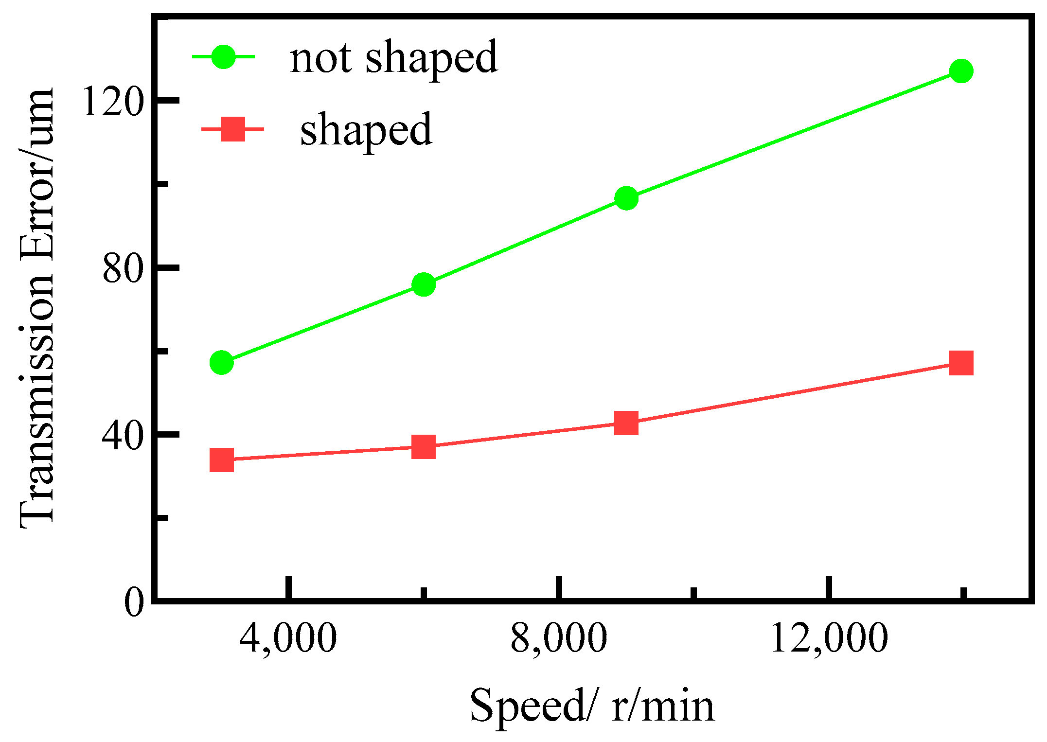
Figure 17 shows the changes in gear transmission error when both modified and unmodified gears operated at a load of 30 N.m. The results indicate that gear modification can effectively reduce gear transmission error under the same load conditions as unmodified gears. Moreover, after gear modification, there was a significant decrease in the variation of transmission errors with an increase in gear speed, resulting in lower gear transmission error during operation.
6. Conclusions
This study presents a measurement method that utilizes strain sensors to determine gear transmission errors. The proposed approach can be applied to measure high-speed dynamic transmission errors of gears in complex environments such as high temperature and oil mist. To overcome the impact of noise interference, anti-interference processing is performed at the physical level during the measurement process, effectively minimizing the influence of environmental noise on the test data. The Mallat algorithm is employed to perform multi-level decomposition of the test data using wavelet decomposition, which separates the high-frequency and low-frequency components in the signal. The resulting test signal under gear operation conditions is analyzed using Fourier transform to obtain the gear’s dynamic strain value in the frequency domain.
The dynamic transmission error of gears at high speeds was computed using the relationship between the dynamic strain value of the gears and the dynamic transmission error. The magnetic grid method and the stress–strain stiffness method were used to test the gear transmission error, and the gear transmission error was obtained at the same speed and varied loads. The stress–strain stiffness approach was validated in transmission error testing. Dynamic testing studies were performed on modified and unmodified gears at various speeds and load situations on a high-speed dynamic testing platform. The results showed that as gear speed increased, transmission error increased while the load remained constant. When the gear speed remains constant, the load increases as the gear transmission error increases. A comparison test on the transmission error of modified and unmodified gears under the same load was performed. The test findings suggest that gear modification can effectively minimize gear transmission error. Furthermore, the employment of strain sensors for testing gear transmission mistakes has enlarged the testing channels for gear transmission errors, providing technical support for transmission system gear research and development.
Author Contributions
Conceptualization, J.Z. and Z.L.; methodology, Z.L.; software, J.Z.; validation, C.L.; formal analysis, C.L.; investigation, C.L.; resources, J.Z.; data curation, J.Z. and C.L.; writing—original draft preparation, C.L.; writing and editing, J.Z.; supervision, Z.L. All authors have read and agreed to the published version of the manuscript.
Funding
This work was supported in part by the 2020 National Key Research and Development Program of China 2020YFB2008100, the National Natural Science Foundation of China under Project 52105061, the Natural Science Foundation of Jiangsu Province under Project BK20200424, the Nanjing University of Aeronautics and Astronautics, Jiangsu Key Laboratory of Precision and Micro-manufacturing Technology, and Sichuan Gas Turbine Establishment, Aero Engine Corporation of China. The authors would like to thank the anonymous reviewers for giving valuable suggestions to improve the quality of their work.
Data Availability Statement
Not applicable.
Conflicts of Interest
The authors declare no conflict of interest.
References
- Peng, J. Analysis of the Influence of Dynamic Characteristics of Gear Transmission System on Transmission Error; Chongqing University of Technology: Chongqing, China, 2019. [Google Scholar]
- Choi, Y.S.; Lee, B.H.; Shin, Y.H. Nonlinear Dynamic Analysis of Gear Driving System due to Transmission Error and Backlash. Trans. Korean Soc. Automot. Eng. 1997, 5, 69–78. [Google Scholar]
- Zhou, W.; Zhu, R.; Liu, W.; Shang, Y. An Improved Dynamic Transmission Error Model Applied on Coupling Analysis of Gear Dynamics and Elastohydrodynamic Lubrication. J. Tribol. 2022, 144, 051601. [Google Scholar] [CrossRef]
- Wei, J.; Gao, P.; Hu, X.; Sun, W.; Zeng, J. Effects of dynamic transmission errors and vibration stability in helical gears. J. Mech. Sci. Technol. 2014, 28, 2253–2262. [Google Scholar] [CrossRef]
- Li, W.; Wang, L.; Chang, S. Exception prediction by dynamic transmission error under slipping friction in hydraulic gear system. J. Tianjin Univ. Engl. Ed. 2013, 19, 6. [Google Scholar]
- Li, F. Error Detection and Analysis of Cylindrical Gear Transmission Based on Digital Image Correlation; Zhengzhou University: Zhengzhou, China, 2020. [Google Scholar]
- Wang, Z.G.; Chen, Y.C. Design of a helical gear set with adequate linear tip-relief leading to improved static and dynamic characteristics. Mech. Mach. Theory 2020, 147, 103742. [Google Scholar] [CrossRef]
- Wan, Q.Z.; Lu, Z.G.; Wang, K.; Dong, X.Z.; Duan, W.G.; Tong, Q.B.; Li, G.B. Precision harmonic gear reducer transmission error analysis. Instrum. Technol. Sens. 2013, 42, 51–54. [Google Scholar]
- Hu, Q.; Liu, Z.; Yang, C.; Xie, F. Research on dynamic transmission error of harmonic drive with uncertain parameters by an interval method. Precis. Eng. 2021, 68, 285–300. [Google Scholar] [CrossRef]
- Wang, G.; Chen, L.; Yu, L.; Zou, S. Research on the dynamic transmission error of a spur gear pair with eccentricities by finite element method. Mech. Mach. Theory 2017, 109, 1–13. [Google Scholar] [CrossRef]
- Yuan, Y.; Wang, Z.; Liu, Z.; Yu, L.; Gang, H. Test and simulation verification of gear transmission error. Mech. Transm. 2019, 43, 144–147. [Google Scholar]
- Lou, J.; Ma, Z.; Lei, D.; He, L. A testing method for dynamic transmission error of high-speed accessory transmission gears in aircraft engines. Mech. Transm. 2020, 44, 164–167. [Google Scholar]
- Benatar, M.; Handschuh, M.J.; Kahraman, A.; Talbot, D. Static and Dynamic Transmission Error Measurements of Helical Gear Pairs with Various Tooth Modifications. J. Mech. Des. 2019, 141, 103301. [Google Scholar] [CrossRef]
- Anichowski, B.; Kahraman, A.; Talbot, D. Dynamic Transmission Error Measurements From Spur Gear Pairs Having Tooth Indexing Errors. In Proceedings of the ASME International Design Engineering Technical Conferences & Computers & Information in Engineering Conference, Cleveland, OH, USA, 6–9 August 2017. [Google Scholar]
- Chun, X.; Chen, S. Experimental study of the effect of assembly error on the lightly loaded transmission error of spur gear with crown modification. J. Low Freq. Noise Vib. Act. Control. 2020, 39, 1039–1051. [Google Scholar] [CrossRef]
- Liang, Z.; Zhao, K.; Liu, Y.; Ye, J. Gear dynamic transmission error measurement system based on photoelectric encoder. Mech. Transm. 2018, 42, 151–156. [Google Scholar]
- Chen, Q.; Jiang, P.; Hu, Z.; Tang, J. High speed straight bevel gear transmission error testing and dynamic performance analysis. Mech. Transm. 2016, 40, 101–105+147. [Google Scholar]
- Peng, D.; Zheng, Y.; Chen, R.; Gao, Z.; Zheng, F. Development of a dynamic testing system for transmission error based on time grating sensors. China Mech. Eng. 2011, 22, 1138–1142. [Google Scholar]
- Palermo, A.; Britte, L.; Janssens, K.; Mundo, D.; Desmet, W. The measurement of Gear Transmission Error as an NVH indicator: Theoretical discussion and industrial application via low-cost digital encoders to an all-electric vehicle gearbox. Mech. Syst. Signal Process. 2018, 110, 368–389. [Google Scholar] [CrossRef]
- Tamminana, V.K.; Kahraman, A.; Vinayaka, S. A Study of the Relationship Between the Dynamic Factors and the Dynamic Transmission Error of Spur Gear Pairs. J. Mech. Des. 2007, 129, 75–84. [Google Scholar] [CrossRef]
- Hotait, M.A.; Kahraman, A. Experiments on the relationship between the dynamic transmission error and the dynamic stress factor of spur gear pairs. Mech. Mach. Theory 2013, 70, 116–128. [Google Scholar] [CrossRef]
- Henriksson, M. Analysis of gear noise and dynamic transmission error measurements. ASME Int. Mech. Eng. Congr. Expo. 2004, 47020, 229–237. [Google Scholar]
- Park, S.; Kim, S.; Choi, J.-H. Gear Fault Diagnosis using Transmission Error and Ensemble Empirical Mode Decomposition. Mech. Syst. Signal Process. 2018, 108, 262–275. [Google Scholar] [CrossRef]
- Chin, Z.Y.; Smith, W.A.; Borghesani, P.; Randall, R.B.; Peng, Z. Absolute transmission error: A simple new tool for assessing gear wear. Mech. Syst. Signal Process. 2021, 146, 107070. [Google Scholar] [CrossRef]
- Sanchez-Espiga, J.; Fernandez-del-Rincon, A.; Iglesias, M.; Viadero, F. Numerical evaluation of the accuracy in the load sharing calculation using strain gauges: Sun and ring gear tooth root. Mech. Mach. Theory 2022, 175, 104923. [Google Scholar] [CrossRef]
- Qu, Y.; Hong, L.; Jiang, X.; He, M.; He, D.; Tan, Y.; Zhou, Z. Experimental study of dynamic strain for gear tooth using fiber Bragg gratings and piezoelectric strain sensors. Sage J. 2018, 232, 3992–4003. [Google Scholar] [CrossRef]
- Rebbechi, B.; Oswald, F.B.; Townsend, D.P. Dynamic measurements of gear tooth friction and load. In Proceedings of the Fall Technical Meeting of the American Gear Manufactures Association, Detroit, MI, USA, 21–25 October 1991. NTRS-NASA Technical Reports Server. [Google Scholar]
- Naresh, K. Raghuwanshi, Anand Parey: Experimental measurement of gear mesh stiffness of cracked spur gear by strain gauge technique. Measurement 2016, 86, 266–275. [Google Scholar]
- Baud, R.V.; Peterson, R.E. Load and stress cycles in gear teeth. Mech. Eng. 1929, 51, 653–662. [Google Scholar]
- Xiao, J.; Guo, N.; Yan, S.; Sun, W.; Zhao, Y.; Liu, J. Comprehensive analysis method and application of gear squealing in commercial vehicle drive axles. Mech. Transm. 2022, 46, 141–146+160. [Google Scholar]
- Lu, H.; Zhang, J.; Pan, K.; Lv, C.; Hou, X.; Li, Z.; Zhang, H. Quasi-Static Transmission Error Measurement Using Micro-Deformation. Iran. J. Sci. Technol. Trans. Mech. Eng. 2023. [Google Scholar] [CrossRef]
- Wang, J.; Chen, F.; Li, P. Research on grounding technology in spacecraft comprehensive testing. Comput. Meas. Control 2010, 18, 246–248+271. [Google Scholar]
- Zhao, M.; Lin, J.; Wang, X.; Liao, Y. Dynamic transmission error analysis for a CNC machine tool based on built-in encoders. In Proceedings of the 2011 IEEE International Symposium on Assembly and Manufacturing (ISAM), Tampere, Finland, 25–27 May 2011; IEEE: Piscataway, NJ, USA, 2011; pp. 1–5. [Google Scholar]
- Yu, Y.; Ge, L.; Li, F.; Hu, C. Study on gamma spectrum wavelet noise reduction based on scintillation detector. J. Phys. Conf. Ser. 2021, 1941, 012027. [Google Scholar] [CrossRef]
Figure 1.
The location of the testing point.
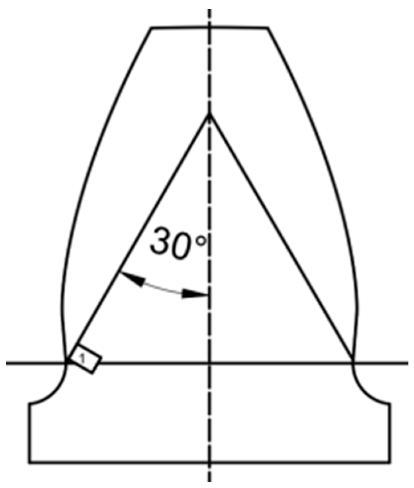
Figure 2.
Principle test bench.
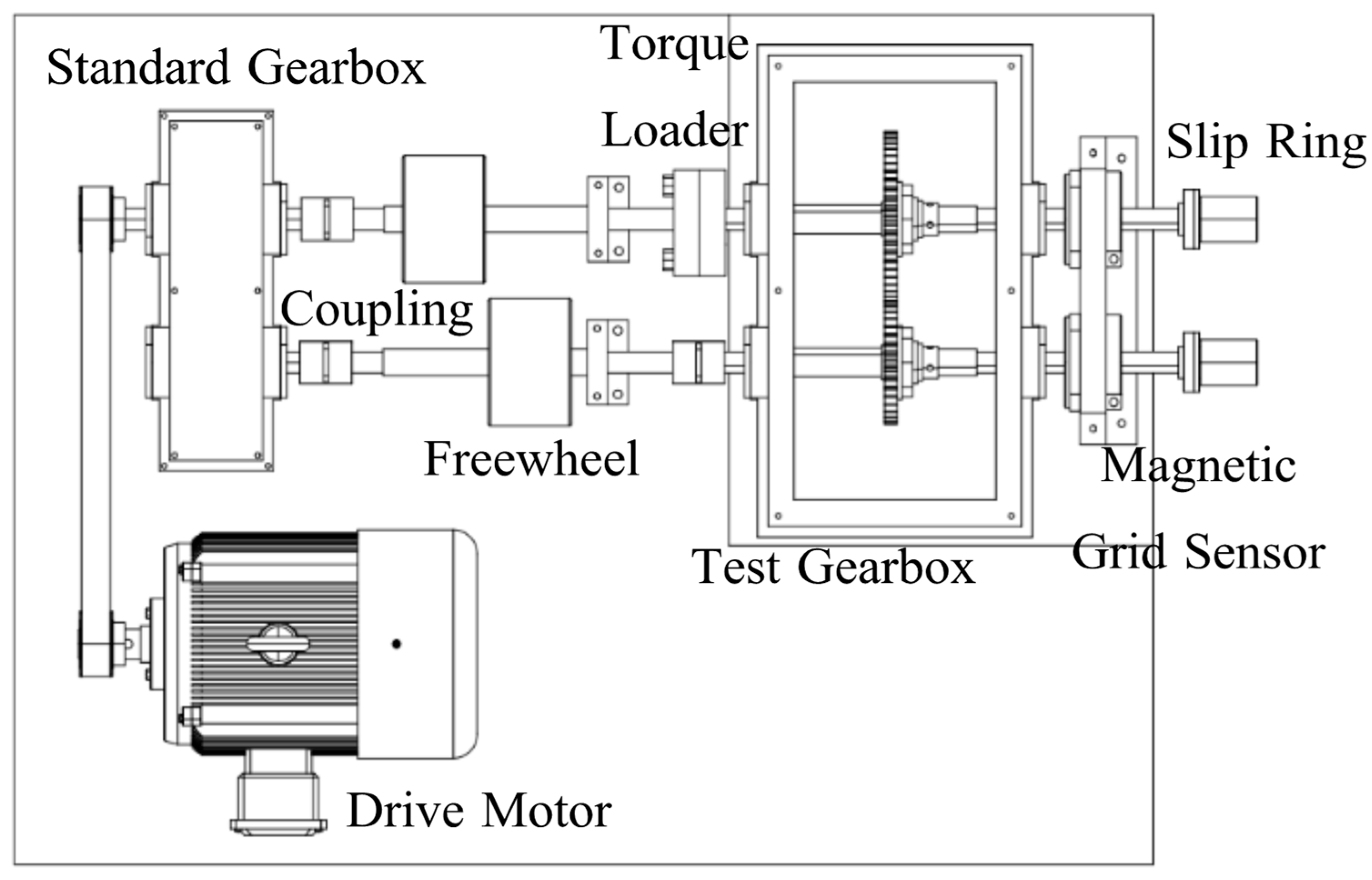
Figure 3.
Gear dynamic transmission error testing platform.
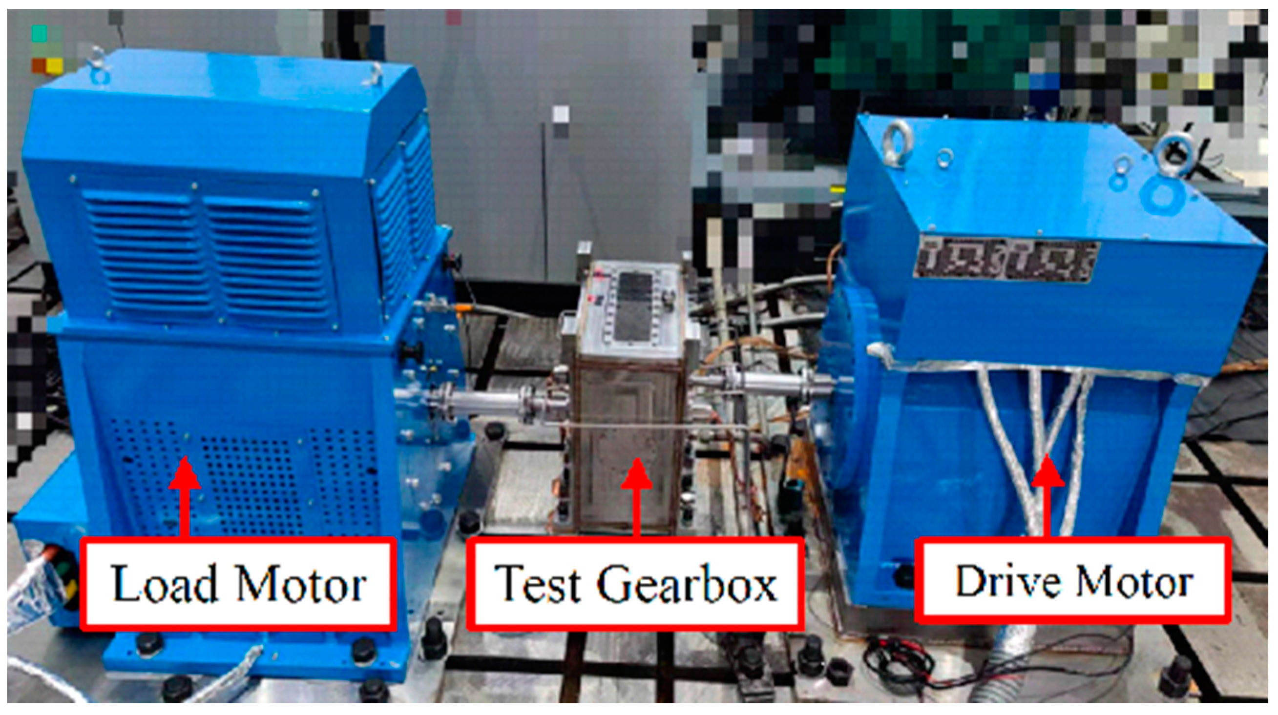
Figure 4.
Test gear with strain gauge attached.
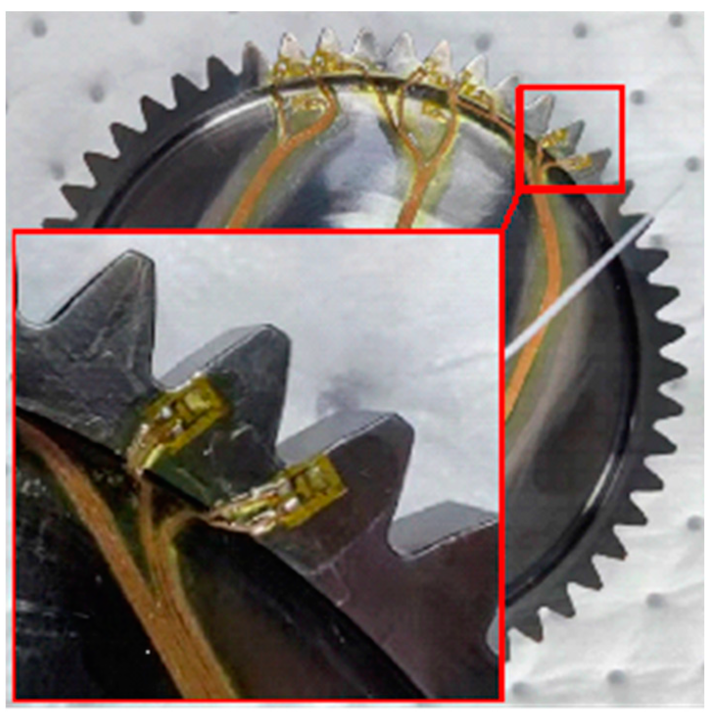
Figure 5.
Acquisition instrument grounding processing.

Figure 6.
Signal line shielding processing.
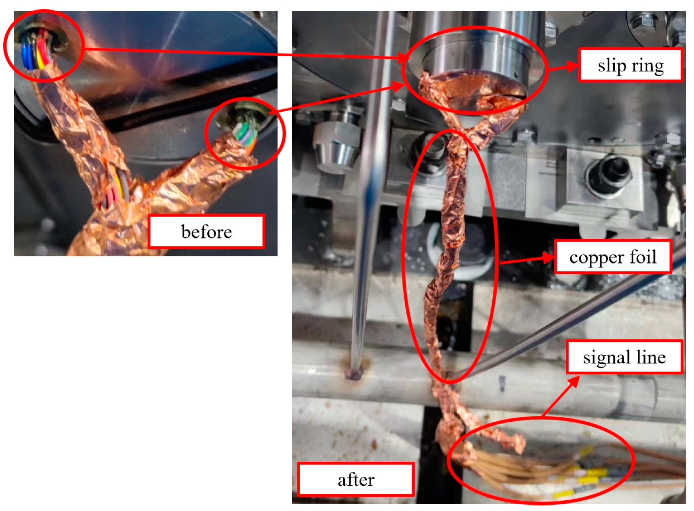
Figure 7.
Power line shielding treatment.

Figure 8.
Comparison of test signals before and after noise reduction.
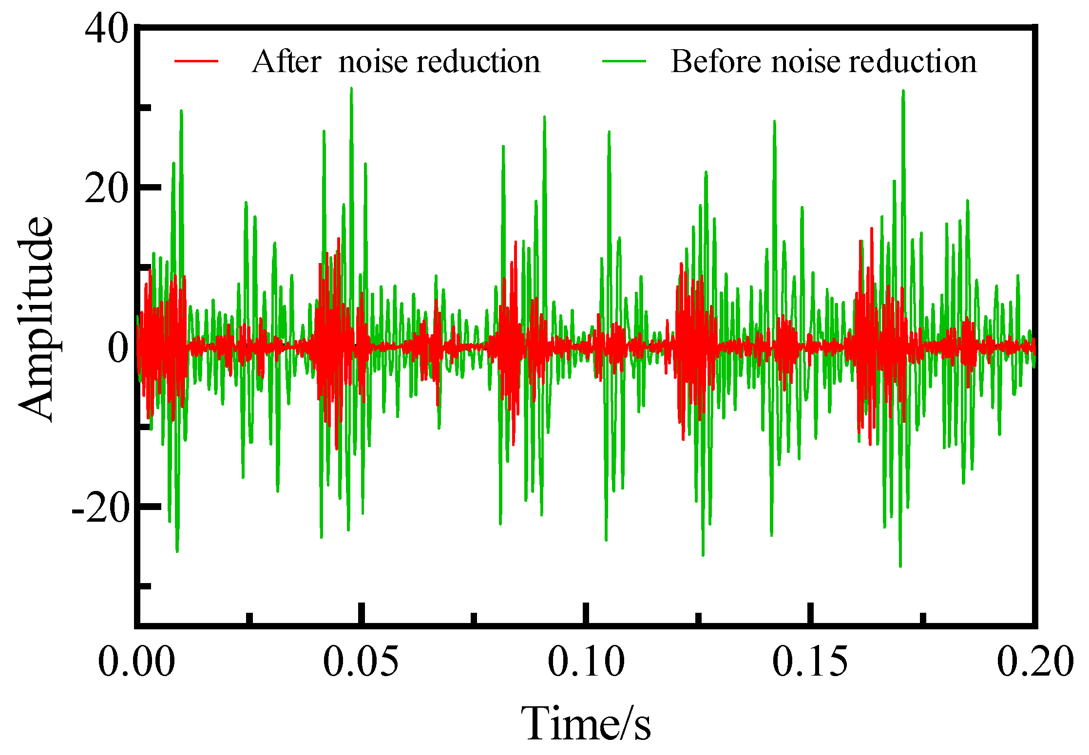
Figure 9.
Test signal decomposition process. In Figure 8, g(n) represents a low-pass filter, and h(n) represents a high-pass filter.
Figure 9.
Test signal decomposition process. In Figure 8, g(n) represents a low-pass filter, and h(n) represents a high-pass filter.

Figure 10.
Transmission error test signal.
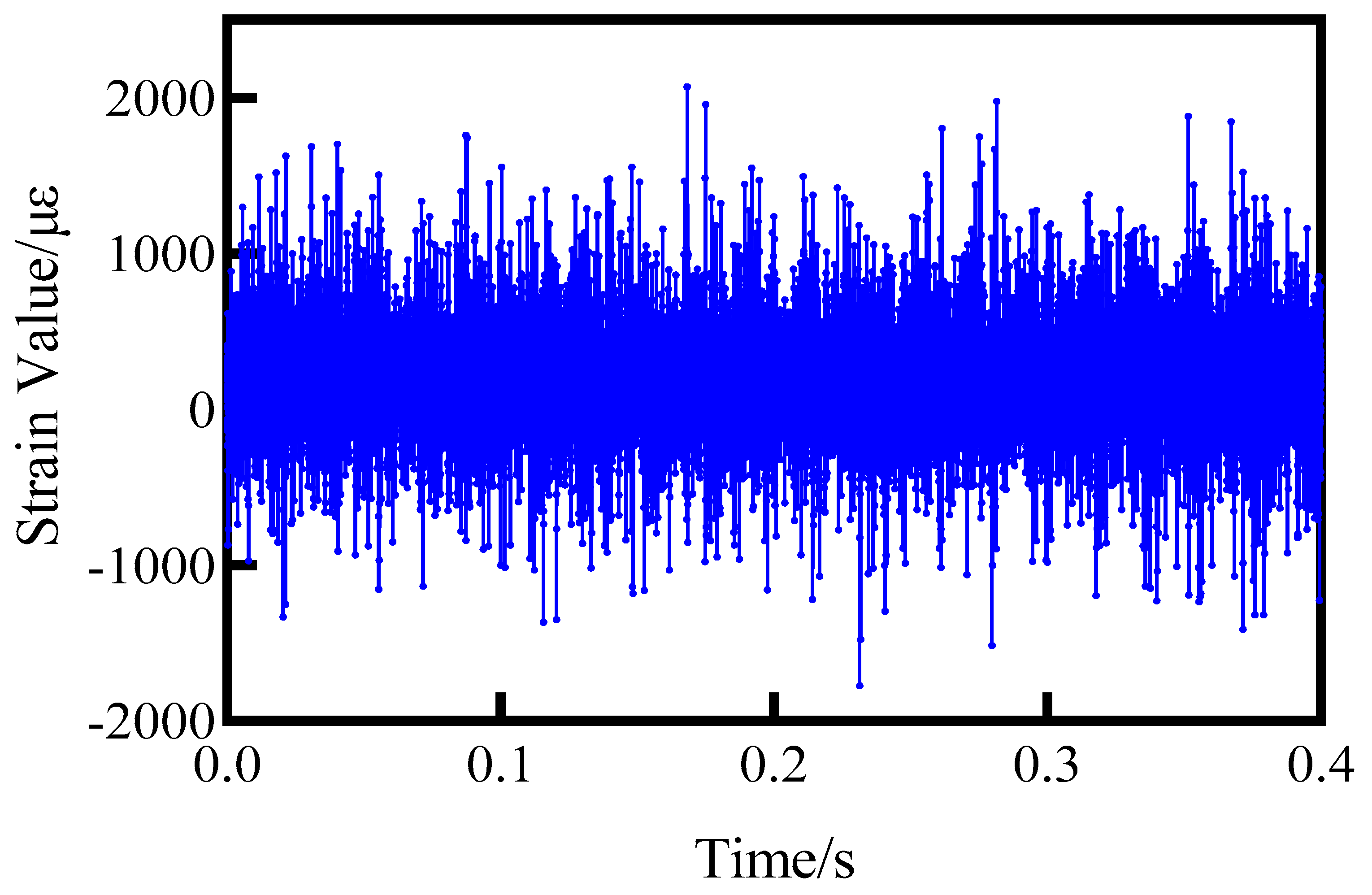
Figure 11.
Processed test signal.
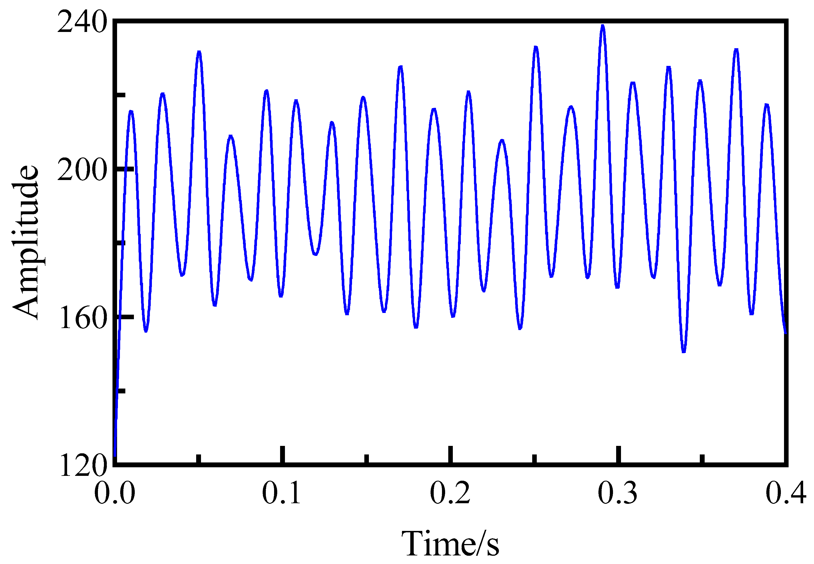
Figure 12.
Spectrum of test signal after noise reduction.
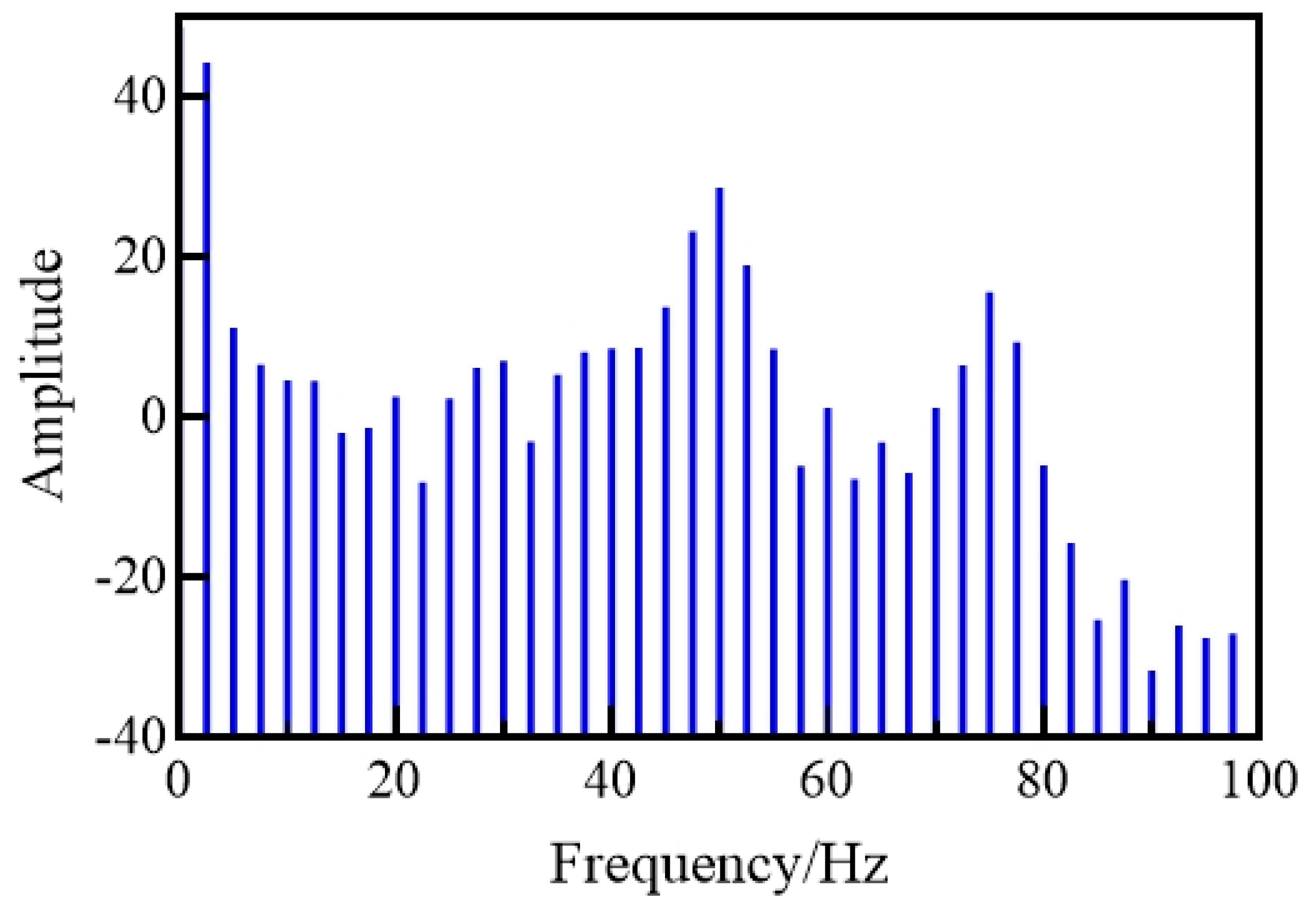
Figure 13.
Comparison of test results under the same load using different testing methods.
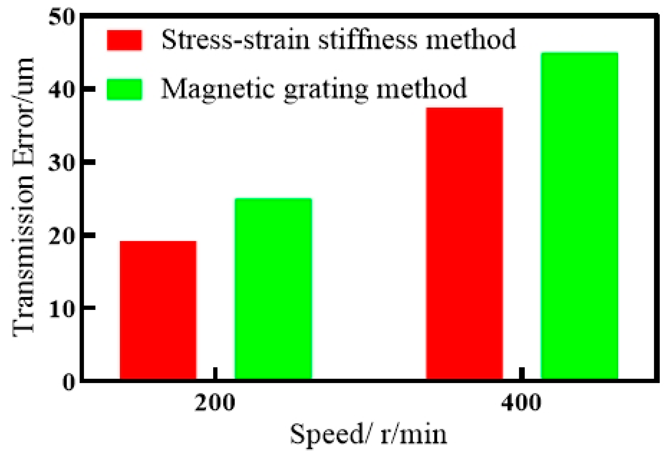
Figure 14.
Comparison of test results under different test methods at the same speed.

Figure 15.
Transmission error of unmodified gear.
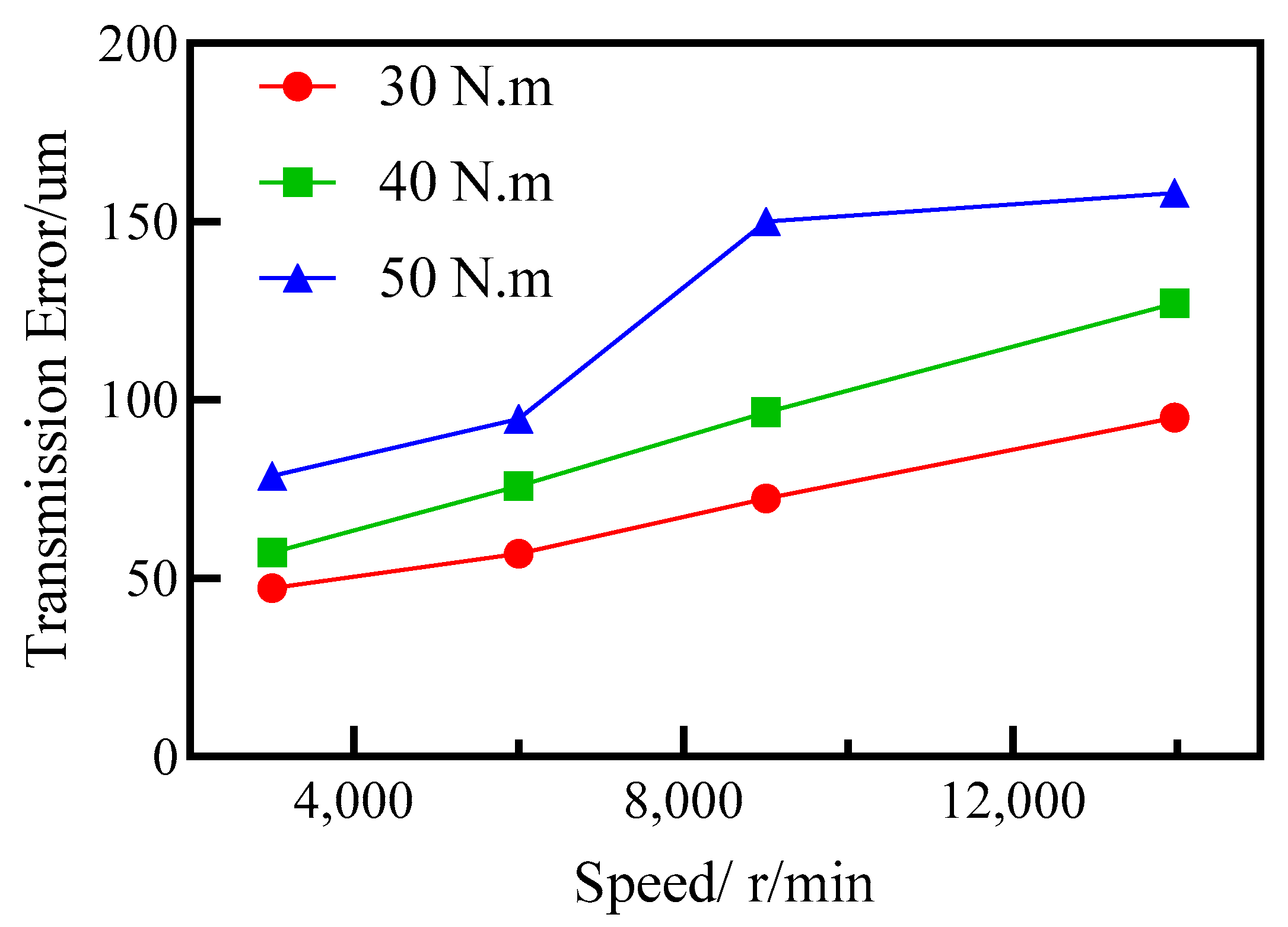
Figure 16.
Modified gear transmission error.

Figure 17.
Comparison of transmission errors between modified and unmodified gears.

Table 1.
Parameters for calculation of gearing errors.
| Transfer Error Calculation Parameters | Parameter Value |
|---|---|
| Modulus of elasticity of gears E | 2 × 10⁵ |
| Coefficient of use | 1 |
| Dynamic load factor | 1 |
| Intertooth load distribution factor | 1 |
| Toothwise load distribution factor | 1.4462 |
| Tooth profile coefficient | 2.81 |
| Stress concentration factor | 1.3357 |
| Helix angle coefficient | 1 |
| Gear mesh stiffness | 1.5 × 10⁶ |
Table 2.
Structural parameters of test gears.
| Gear Parameters | Driving Gear | Driven Gear |
|---|---|---|
| Number of teeth | 53 | 37 |
| Modulus | 3 | 3 |
| Pressure angle | 20° | 20° |
| Tooth width | 12 mm | 12 mm |
| Shaft diameter | 20 mm | 20 mm |
Disclaimer/Publisher’s Note: The statements, opinions and data contained in all publications are solely those of the individual author(s) and contributor(s) and not of MDPI and/or the editor(s). MDPI and/or the editor(s) disclaim responsibility for any injury to people or property resulting from any ideas, methods, instructions or products referred to in the content. |
© 2023 by the authors. Licensee MDPI, Basel, Switzerland. This article is an open access article distributed under the terms and conditions of the Creative Commons Attribution (CC BY) license (https://creativecommons.org/licenses/by/4.0/).
Share and Cite
MDPI and ACS Style
Zhang, J.; Lv, C.; Li, Z. Investigation of High-Speed Dynamic Transmission Error Testing Using Gear Strain. Machines 2023, 11, 956. https://doi.org/10.3390/machines11100956
AMA Style
Zhang J, Lv C, Li Z. Investigation of High-Speed Dynamic Transmission Error Testing Using Gear Strain. Machines. 2023; 11(10):956. https://doi.org/10.3390/machines11100956
Chicago/Turabian StyleZhang, Jian, Chuanmao Lv, and Zhengminqing Li. 2023. "Investigation of High-Speed Dynamic Transmission Error Testing Using Gear Strain" Machines 11, no. 10: 956. https://doi.org/10.3390/machines11100956
Note that from the first issue of 2016, this journal uses article numbers instead of page numbers. See further details here.