
Bearing Current and Shaft Voltage in Electrical Machines: A Comprehensive Research Review


1
Department of Electromechanical, Systems and Metal Engineering, Ghent University, 9000 Ghent, Belgium
2
FlandersMake@UGent—Corelab MIRO, 3001 Leuven, Belgium
3
Department of Electrical Engineering, Faculty of Engineering, Menoufia University, Menoufia 32511, Egypt
*
Author to whom correspondence should be addressed.
Machines 2023, 11(5), 550; https://doi.org/10.3390/machines11050550
Submission received: 25 April 2023
/
Revised: 10 May 2023
/
Accepted: 11 May 2023
/
Published: 12 May 2023
(This article belongs to the Special Issue Advanced Power Electronic Technologies in Electric Drive Systems)
Abstract
:The reliability assessment of electric machines plays a very critical role in today’s engineering world. The reliability assessment requires a good understanding of electric motors and their root causes. Electric machines mostly fail due to mechanical problems and bearing damage is the main source of this. The bearings can be damaged by mechanical, electrical, and thermal stresses. Among all stresses, the researcher should give special attention to the electrical one, which is bearing current and shaft voltage. This review paper introduces a comprehensive study of bearing current and shaft voltage for inverter-fed electric machines. This study aims to discuss several motor failure processes, as well as the sources and definitions of bearing current and shaft voltage. The different kinds of bearing currents are addressed and the parasitic capacitances, which are the key component to describe bearing current, are determined. Several measurement approaches of bearing current will be discussed. Furthermore, modeling of bearing current will be covered together with the machine’s parasitic capacitances. Moreover, the different bearing current mitigation techniques, as described in many papers, will be thoroughly addressed. The use of rewound multiphase machines for mitigation of bearing current will be proposed and compared to a three-phase machine. Finally, various pulse width modulation techniques of multiphase systems that reduce bearing current and shaft voltage will be investigated, and the findings described in the literature will be summarized for all techniques.
1. Introduction
Despite the fact that the bearing current problem in electrical machines has been well-known for almost a century [1], it is still a relevant focus for ongoing research. Failures brought on by bearing currents result in significant mechanical damage to electrical machines, which causes expensive maintenance and operational costs [2]. Magnetic asymmetry and electrostatic discharge are the main causes of bearing currents at that time. The magnetic asymmetry is caused by the inability to produce a motor with absolute accuracy, due to such issues as rotor eccentricities and asymmetrical windings [3].
With the emergence of inverter-fed electric machines and their increasing popularity, a third cause of bearing failure appeared. The new source is a high-frequency common mode voltage (CMV) that will produce a high-frequency common mode current [4,5]. The problem can possibly become worse with pulse width modulated (PWM) drives that employ extremely fast switching components such as silicon carbide (SiC) or gallium nitride (GaN) switches to minimize converter losses [6,7,8]. The generated high-frequency common mode current due to PWM flows through the winding of the machine and then to the stator of the machine. A circulating flux will then be produced in the frame, leading to a high-frequency inductive circulating bearing current [9,10]. Moreover, there are additional types of bearing currents, such as electric discharge machining (EDM) bearing currents or high-frequency capacitively bearing current [11,12]. EDM current is generated when the voltage across one of the bearings exceeds a threshold and a breakdown happens [13]. A more detailed explanation of these currents is given later in the paper. Several proposed solutions for mitigating bearing failures were proposed in the literature, including the development of ultralow inductance switching power cells [14], the installation of electrical field emission (EMI) filters [15,16,17], the use of electrically-insulated bearings and shaft grounding brushes [18], and modified PWM techniques [19,20,21].
Numerous studies have been conducted to better understand the fundamental processes of bearing currents and the appropriate mitigation measures [22,23,24,25,26,27,28,29,30]. The shaft voltage sources and their generating methods were thoroughly described in [22]. Moreover, strategies for regulating and/or eliminating these sources were examined so that users might have a better understanding of how these voltages and currents are formed. The testing for detecting shaft voltage sources, as well as their potential circuits, were also described in [22]. The authors of [23] presented a number of practical strategies for reducing bearing currents such as the selection of a carrier frequency between 1.5 kHz and 3 kHz, insulated bearings, shaft ground brushes, a common mode filter, and using a special cable to reduce common mode current. The work in [23] lacks theoretical and mathematical analysis. The authors of [24] offer an in-depth overview of bearing currents, focusing on practical and simple approaches for mitigating bearing current in conventional PWM inverter drives, such as inverter output filters and insulated bearings, without considering mitigation methods that require hardware and/or motor modifications. The effectiveness and losses of several proposed mitigation strategies for bearing currents, EMI, and motor terminal overvoltage are assessed and compared in [25] using laboratory measurements and user-friendly application assessments. The modelling of an induction motor under a bearing fault state was reviewed in [26]. It was proven that model-based techniques are more advantageous than experiment-based techniques in bearing fault detection. The authors of [27] reviewed and evaluated EMI modelling methodologies for various function units in a variable-frequency drive system, such as induction motors, motor bearings, and rectifier-inverters, in terms of the applicable frequency range, model parameterization, and model correctness. The frequency of the EMI phenomena is in the range of several to tens of MHz, which is greater than the frequency of the bearing currents; therefore these models, which were built primarily for EMI analysis, have limited checks on the bearing currents. A comprehensive study of all aspects of the shaft voltage and bearing current phenomena was presented in [28], along with a review of bearing failure approaches with a focus on electric vehicles (EV) and hybrid EV motors. The work in [29] introduced a summary of the methods for assessing the state of bearings as well as low- and high-frequency inverter-generated shaft voltages. The bearing current modelling and mitigation methods for electrical machines with variable-frequency drives were reviewed in [30]. However, the bearing current mitigation method using multiphase systems was not introduced in the previous review papers about this topic. The literature also lacks a thorough analysis of this subject that covers every aspect in depth.
This paper introduces a comprehensive review study about bearing current and shaft voltage. The first part of this paper discusses the different motor failure mechanisms. In the second part, the sources and the definition of bearing current and shaft voltage will be introduced. Furthermore, different types of bearing currents and parasitic capacitances will be discussed. The third part of this paper investigates and compares the measurement techniques that can be used to measure bearing current and shaft voltage. The modelling approaches to bearing currents will be presented in the fourth part. Moreover, the analytical calculation of the machine parasitic capacitances will be introduced. Finally, the various mitigation techniques of bearing currents will be discussed in detail. The mitigation using the rewound multiphase machines will be proposed and compared with the three-phase ones. Moreover, various PWM strategies of the multiphase systems that mitigate bearing current and shaft voltage will be analyzed.
2. Failure Modes of the Electric Motors
The evaluation of motor failure mechanisms can be carried out in a variety of ways. According to motor failure root-cause studies, there are generally three main failure mechanisms. The most crucial failure mode is electrical-related failure, which is brought on by problems with motor winding insulation, winding short circuits, overloading, and other problems [31]. The degradation of insulating material is frequently due to winding temperature limits being exceeded. Coils can be damaged by a winding current that is too high due to an overloading problem. The second type of failure is magnetic failure, which often happens when a permanent magnet (PM) becomes thermally demagnetized. A PM may be thermally demagnetized for a variety of reasons, including high motor operation temperatures, shock, vibration, and strong magnetic fields produced by the stator windings. The mechanical failure of a motor’s structure and components is the third failure mode. Bearing failures are typically seen in this failure scenario. Broken or loosened rotor bars are another frequent failure mode. Most mechanical breakdowns are often the consequence of slow processes such as mechanical wear and the gradual deterioration of the material characteristics. The damaged parts keep showing recognizable symptoms throughout the process until they totally fail. This is not the same as the majority of electronic component failures, which occur abruptly and without notice. Despite the reliability and ease of construction of induction machines (IMs), studies have indicated that the yearly motor failure rate is roughly estimated at 3–5% per year, and in severe circumstances up to 12% [32]. The cost of the downtime in a production caused by a motor failure might be substantial or even exceed the cost of a new motor. Under some circumstances, a motor failure might stop the entire production of the factory.
In order to address motor failure modes according to main causes of failure, IEEE presented a thorough study in three parts [33,34,35] based on data collected from 1141 motors that were larger than 200 hp and no more than fifteen years in operation. The first part of this research gave overall findings based on motor type categories. The second part integrated several categories and addressed the issues that were raised in the first part. The third part of the survey findings was intended to address new inquiries and comments as well as to give more detailed assessments of topics that had not been previously covered. The Electric Power Research Institute (EPRI) has carried out a similar examination into motor failure modes [36]. Although EPRI concentrated only on faulty motor components, it gave comparable results with IEEE. Venkataraman et al. [32] combined the results of these two studies, as shown in Table 1. Table 1 shows that bearing failures and failures related to the stator insulation are the most frequent causes of motor failures. Mechanical breakdowns can be caused by high vibration. In addition, many malfunctions are caused, directly or indirectly, by excessive operating temperatures.
3. Bearing Current and Shaft Voltage
This section introduces the sources, the definition, and the types of bearing currents and shaft voltage. The most frequent cause of electric motor failure is bearing failure [37,38] as has been discussed in the previous section. However, there are other potential causes as well, such as winding and insulation failure, as has been discussed in the previous section. Depending on the application and duty cycle of the bearing, a variety of causes can lead to bearing failure. Bearing currents are responsible for 9% of all bearing failures [31]. The major portion of bearing failures in electric drives are produced by mechanical or thermal problems. Misalignment, insufficient lubrication, and inadequate maintenance can all lead to these types of failures [39]. While all failure types are essential to address, the focus of this work is on bearing failures because of bearing current, which has become increasingly prominent in recent years. This is due to the increased utilization of high-frequency drive components in electrical systems such as silicon carbide (SiC) and Gallium nitride (GaN) switches [31].
3.1. Sources of the Bearing Current and Shaft Voltage
Bearing currents in electric motors can be caused by a variety of sources. The three major sources of bearing currents are magnetic asymmetries, electrostatic discharge, and common mode voltage combined with fast switching rates of the switches of the inverter, as highlighted in Figure 1. The first two sources are reasonably well discussed and have been investigated for a long time [40,41,42,43,44].
3.1.1. Magnetic Asymmetries
There are two key reasons for magnetic asymmetry. The first is due to the incapability of producing a motor with extreme accuracy, e.g., rotor eccentricities and asymmetrical windings [45,46,47,48]. The second is brought on by the inverter’s unbalanced voltage signal. Any mechanical or electrical asymmetries in the motor windings will produce an unbalanced flux that will encircle the shaft and result in a voltage that is greater than zero. This may cause circulating low-frequency currents to flow into the motor as illustrated in Figure 2. The most frequent reason for bearing current in sine-wave driven motors is magnetic asymmetry [49]. Normally, these low-frequency currents move through conducting components such as the shaft, bearing races, bearing balls, and the frame. Insulation, in the form of insulated bearings, can be used to disrupt the conducting channel in order to deal with these sorts of bearing currents [50,51].
3.1.2. Electrostatic Discharge
Composite materials and polymer materials with a dielectric nature are frequently used in electric vehicle construction to reduce weight, such as carbon-fiber reinforced plastic body structural components, high thermal conductivity insulating polymer cooling systems, and rubber sealing rings. Triboelectrification can cause large charge separation between the surfaces of these components and build up large electrostatic charges [52]. As a result of this electrostatic field, a voltage difference can appear between the shaft and ground [53]. As the electrostatic field approaches the breakdown strength of the lubricant, the stored charges are discharged to produce discharge currents. The discharged current is known as the electric discharge machining (EDM) current.
3.1.3. Common Mode Voltage
In order to achieve variable speed control in electric drive applications, PWM three-phase inverters with fast switching components such as SiC and GaN switches are frequently utilized in electric motors in recent years [54]. The third type of bearing current is formed as a result of the unbalanced voltage generated by these fast switching three-phase inverters. This type of bearing current is more complicated and has recently become a cause for concern due to the increased interest in employing high switching semiconductor technology in three-phase drive systems. New capacitive pathways for current to flow are created by these high-frequency voltage pulses [55,56,57,58]. High-frequency common mode voltages produced by the inverter are the main source of this type of bearing current. The voltage between the ground and the three-phase neutral is known as the common mode voltage [59,60]. The common mode voltage (CMV) can be described as follows:
where is the phase voltages of phase A, B, and C, respectively. The CMV would effectively be zero if the motor is connected to an electrical supply with ideal and symmetrical sinusoidal waveforms. This guarantees that there will be no potential difference between the ground and the three-phase neutral. In contrast, a grid connection is currently unfeasible for electric drive systems, necessitating the use of an inverter. The output voltage from the inverter is not perfectly balanced. Voltage waveforms generated by the inverter seen in Figure 3 can be observed in Figure 4. Figure 4a shows the output phase voltage and the CMV of the three-phase inverter. Figure 4b shows the zoom-in view of the CMV and generated shaft voltage. The common mode voltage’s magnitude and frequency are related to the DC link voltage and the inverter carrier frequency, respectively [60]. On the one hand, the output voltage waveform will be smoother at higher switching frequencies, which will reduce noise, torque ripple, and losses. On the other hand, fast switching will inject high-frequency harmonic distortion into the system. This high-frequency content might cause bearing currents in the machine because of the sudden change in voltage over time (dv/dt) [59].
The voltage can be induced on the shaft during the rise or fall of the CMV waveform shown in Figure 4b. This high-frequency voltage increases on the shaft until it exceeds the breakdown voltage of the lubricating film inside the bearing. Consequently, this causes a high current discharge pulse to pass through the bearing. This may cause a temperature increase, which may cause the bearing race to melt [61].
3.2. Bearing Voltage Ratio and Motor Capacitances
Electrical machine capacitances often have little impact during line operation. When the machine is exposed to a common voltage that has high-frequency components, they have a significant action in that case. The parasitic capacitances in an electric machine can be described as follows (see Figure 5) [62,63]:
3.2.1. Stator Winding to Stator Frame Capacitance
Stator winding to stator frame capacitance per phase () is the capacitance between the high-voltage stator winding and the grounded potential of the stator iron. Electrical insulation exists between the stator iron stack and the winding copper to separate the various voltage levels.
3.2.2. Stator Winding to Rotor Capacitance
The stator winding to rotor capacitance for all three phases () is determined by the air gap, slot wedges, and winding insulation used to separate the rotor surface from the stator winding.
3.2.3. Rotor to Frame Capacitance
The rotor to frame capacitance () is determined by the air gap, the rotor surface and the stator iron stack surface, particularly the stator teeth tips.
3.2.4. Phase to Phase Capacitances
The phase-to-phase capacitance () is the capacitance between the winding portions of the various phases A, B, and C in the winding overhang, where they are only separated by special insulating paper which is known as phase-separation.
3.2.5. Bearing Capacitance
The bearing behaves like a capacitor () while the lubricating film is unbroken, which means that it possesses insulating properties.
The rotor to frame capacitance, stator winding to rotor capacitance, and bearing capacitance combine to create a capacitive voltage divider in the presence of an unbroken lubricating coating of the bearing, which insulates the stator iron from the rotor. This is shown in Figure 5b. This voltage divider produces the bearing voltage () over the bearing as a function of the common mode voltage (CMV) at the motor terminals. Bearing Voltage Ratio, abbreviated as “BVR”, is the ratio between the bearing voltage and the common mode voltage at the motor terminals. This ratio can be given as follows [62]:
3.3. The Types of Bearing Current
Many authors have documented the phenomenon of extra bearing currents in variable-speed drive systems because of fast-switching IGBT inverters [64,65,66,67,68,69,70,71,72]. The CMV is the source of these bearing currents. IGBTs generally have short rise times of several nanoseconds, which results in high dv/dt values that reaches 10 kV/µs [72]. As was mentioned before, the high-frequency components of this voltage interact with the machine’s capacitances. The machine’s capacitances are affected by the higher-frequency components of this voltage, as has been discussed in the previous section.
Bearing currents caused by inverters may be divided into four categories. The first two are concerned with how the bearing voltage is impacted by the CMV. The remaining two currents are brought on by the ground currents caused by the interaction of the capacitance between the stator winding and the stator frame and the high dv/dt CMV. This is also highlighted in Figure 6.
3.3.1. Capacitive Bearing Currents
The CMV at the stator windings results in a voltage drop across the bearing between the inner and the outer race. The lubricating insulating layer and the races and the balls of the bearing create capacitance () at low bearing temperature (25 °C) and motor speed of 100 rpm [62]. The thickness of the lubricating film in the bearing’s load zone is a few nm at standstill and low motor speed less than 100 rpm. Conducting electrons can quickly cross this gap if voltage is provided due to the quantum-mechanical tunnel effect. Here, the bearing serves as an ohmic resistance. Due to hydrodynamic factors, the lubricating coating of the bearing is generally some µm thicker, at speed higher than 100 rpm, than its thickness at standstill. The bearing functions as a capacitor and this lubricating film has insulating qualities.
Along with the bearing capacitance, the dv/dt over the bearing causes minor capacitive bearing currents between 5–10 mA which can be determined as in (3). This current flows from the stator winding to the rotor, then to the motor bearing, and then to the motor frame, as clarified in Figure 7.
At a low motor speed less than 100 rpm and a typical bearing temperature (70–90 °C), the lubricant coating of the bearing may be bridged by metallic contact, losing its insulating properties, and behave as an ohmic resistance. The produced capacitive bearing current has a small value that is less than 200 mA. Due to its small magnitude, this current causes no danger to the bearing. The best-case and worst-case operating circumstances for the bearing are affected by the temperature of the bearing, since it influences the lubricant’s characteristics. When the bearing temperature increases under constant loads, the peak-to-peak EDM current’s maximum value is changed from a lower speed to a higher speed [73].
3.3.2. Electrostatic Discharge Currents
As previously described in (2) and in the healthy case of the lubrication film, a bearing voltage is obtained as a result of the CMV. The bearing voltage can be determined as follows:
BVR typically fluctuates between 3% and 10% [74]. The peak of the bearing voltage can reach 30 V when taking into account that the voltages of the AC supply in electric drive systems are at least 300 V. Bearings typically have lubricant films between 0.1 and 1.4 microns thick that can endure voltages between 1.5 and 21 V, e.g., dielectric strength is 15 V/μm [75,76]. As a result, it is possible that electrical breakdowns will take place, leading to the production of electrostatic discharge machining (EDM) currents. A 1.5 kW induction motor’s EDM currents can have an amplitude between 0.2 and 1.4 A [77]. The EDM currents flows from the shaft to the inner race of the bearing, then via the rollers, then via the outer ring, and then to the frame, as shown in Figure 7 [78]. EDM currents do not directly correlate with the CMV wave’s rising time, in contrast to the capacitive currents, which occur at switching times. The lubrication film thickness is influenced by the load, speed, and lubricant viscosity in real operating conditions. The history of the discharge, the surface roughness at the bearing interfaces, the uniform distribution of the lubricant, and the oscillations in mechanical operation also all relate to the discharge. These factors mean that, despite the possibility of EDM currents being more probable with high CMV, their occurrence is more likely to be random [79].
3.3.3. Circulating Bearing Currents
Because of the stator winding to frame capacitance Cwf, the high dv/dt at the motor terminals results in an extra ground current, e.g., common mode current. These currents have a frequency content between 100 kHz to many MHz. The motor shaft is surrounded by a circular magnetic flux that is produced by the ground current as shown in Figure 8a. A shaft voltage is induced by this flux along the motor shaft. A circulating bearing current called flows in a loop from the stator frame to the shaft to the drive end if the shaft voltage is high enough to penetrate the bearing’s lubricating film and damage its insulating properties. Bearing currents in both bearings are flowing in the opposite direction with this type of bearing current, which is diferential in nature as shown in Figure 8b. Peak bearing current amplitudes vary depending on motor size, e.g., 0.5–20 A for power rating up to 500 kW.
3.3.4. Rotor Ground Currents
A portion of the total ground current may flow as rotor ground current if the motor is grounded via the driving load. Depending on the stator housing and the rotor’s high-frequency-grounding impedances, the rotor ground current may increase significantly as motor size increases. The rotor ground current is particularly dangerous to the bearings and can quickly damage motors since it almost entirely goes through the motor’s bearing and the driven load’s bearing after crossing the conductive connection, as illustrated in Figure 9 [62].
4. Measurements of Bearing Current and Shaft Voltage
This section highlights the experimental methods that have been used to measure the shaft voltage and bearing current. Although manufacturers often recommend a bearing voltage limit of 5 V for medium voltage motors, no limits for shaft or bearing voltages of machines operating with inverters are currently defined [80]. Besides that, there are no established standardized tools or techniques for detecting this voltage [81]. The authors of [82] compared several shaft current measuring methods. It has been noted that the IEEE 112 shunt current approach [81] is inappropriate. The shaft current is not accurately reflected by this approach, which instead creates a low-impedance channel between the shaft ends. It is typically difficult to monitor bearing currents if no measuring instruments have been put on location. The real shaft current, including the high-frequency circulating current, may be measured by installing a Rogowski coil around the shaft within the machine [82,83]. Such a technique requires a difficult motor preparation and is difficult to use in the field. Nonetheless, ABB makes extensive use of Rogowski coils, particularly to track ground currents linked to high dv/dt on equipment powered by inverters [84]. Most high-frequency bearing current measurements use intrusive techniques that need appropriate motor arrangements [62,82]. The bearing and the frame are generally separated by an electrical insulator. After that, a low impedance wire is connected in parallel with the insulator. The current through this wire is then measured. It should be noted that this approach only offers an estimate of bearing current [83]. Moreover, determining the extent of potentially dangerous bearing currents is difficult since bearings vary depending on machine size and application. Consequently, researchers often define the apparent bearing current density and conclude that bearing current densities lower than 0.8 A/ are tolerable for bearing life [85,86,87]. The use of shaft brushes, such as the AEGIS Shaft Voltage Probe [80,88], in close proximity to the bearing provides an easy but intrusive technique to monitor the bearing voltage with a wide bandwidth as shown in Figure 10.
Non-intrusive radio-frequency (RF) measurements are now preferred in order to find high-frequency discharge bearing currents [63,89,90,91]. The technique assumes that a portion of the energy from the high-frequency discharge current pulse is released close to the machine. The idea is to count the number of pulses that are transmitted beyond a specified threshold and are received within a specific time frame. This is known as the discharge activity (DA), which is used in [63] as a measure of how well the bearing is handling high-frequency discharge currents. The electrical discharge detector pen from the manufacturer SKF [92] can be utilized to count the number of discharges and, thus, assess the extent and severity of the bearing problem if high-frequency discharge voltages on one or more of the bearings are detected. According to the application, one or more measuring techniques may be used to find and keep track of electrical events occurring inside the bearing. The methods for measuring HF bearing currents used in industry are listed in Table 2. It should be noted that one measuring method will only give a partial view of the phenomenon.
5. Modelling of Bearing Current
This section introduces the modelling of the bearing current of electrical motor drive system. The lumped-parameter circuit models need an investigation to produce realistic values of the circuit parameters in order to accurately represent the complex geometry and material configuration of a typical electrical machine. Circuit parameters such as the impedance between the stator frame, the stator windings and the rotor can be extracted from measurements by means of an impedance analyzer. The output of LCR circuit models is calibrated using the measured output waveforms [93,94]. In [95], a general high-frequency lumped-parameter model of a three-phase electric motor with symmetrical phase winding representation was suggested including star and delta connections. An iterative process was used to determine the parameters in order to match the measured differential and common mode impedance curve. Similar methods were introduced with different data fitting approaches such as genetic algorithm [96], vector fitting method of [97], least square data fitting method [98], and trial and error technique [99]. The circuit parameters can be analytically determined instead of using measurement approaches. The well-known different electrode configurations of capacitance (plain plate and the cylinder shape) can be used in the analytical approach.
5.1. Analytical Calculation of Machine Capacitances
The stator winding to stator frame capacitance (), shown in Figure 5a, can be considered as a parallel plate capacitor. This capacitance is represented by a sequence of /3 parallel plate capacitors and can be calculated as follows [62]:
The area of the electrodes of this capacitor is calculated by multiplying by the axial length of the stator lamination stack () by the circumference of the stator slot (. In (5), , and represent the number of stator slots, permittivity of air (8.8542 × ), relative permittivity of slot insulation and slot insulation thickness, respectively. Moreover, is the form factor which considers the irregular surface of the coils. The form factor () is determined by the slot insulation, the thickness, and the wire diameter [62].
The rotor to frame capacitance (), shown in Figure 5a, can be considered as a cylindrical capacitor with a Carter coefficient () which is used to compensate the effect of slot opening. A 15–30% underestimation of the rotor to frame capacitance () in squirrel cage induction machines has been demonstrated when the cage rings are neglected [100]. The rotor to frame capacitance () can be analytically calculated from (6) [62]. In (6), and are the outer diameter of rotor lamination and air gap length, respectively.
The stator winding to rotor capacitance (), shown in Figure 5a, is created by the windings of the stator and the external surface of the rotor. As there is a relatively big airgap length and a small surface area between the stator winding and the rotor, the value of is low in comparison to the capacitances of other components. Nonetheless, it is the main source of bearing voltage; see Section 3.3.2. The stator winding to rotor capacitance is represented by a sequence of parallel plate capacitors. Each parallel plate capacitor is represented by four series-connected capacitors, including the capacitance of the air gap, the slot opening height, the slot wedge, and the top slot insulation [62]. The equivalent capacitance of air gap and slot opening height () can be calculated from (7). The equivalent capacitance of slot wedge and slot insulation () can be calculated from (8). The stator winding to rotor capacitance () is given by (9). In (8), and represent the slot opening width and height, respectively. In (9), represents the thickness of the slot insulation and the slot wedge.
As has been previously discussed in Section 3.2.5, the bearing acts as a capacitor, as shown in Figure 11. The complex geometrical structure makes it extremely challenging to calculate capacitance. A ball bearing’s capacitance is made up of two capacitances that are connected in series: one from the ball to the inner bearing race and the other from the outer bearing race to the ball as shown in Figure 11. Because of the substantial distance between the inner and outer bearing races, the parallel capacitance between them is substantially lower. It is therefore ignored. Because the bearing’s two capacitances, and , are assumed to be equal, the bearing capacitance () is half the capacitance between the bearing race and balls and can be determined as follows:
In (10), and represent the thickness of the lubricating film and the Hertzian contact area, respectively [62].
5.2. Finite Element Modeling and Calculation of EDM Current
Such previously simplified analytical approaches are extensively utilized to determine parasitic capacitances for both induction machines and PM machines due to their simplicity and direct physical relationship to known dimensions [62,74] and [101,102]. The complex stranded windings are treated as a single node by the previously mentioned analytical techniques. Hence, it is unable to account for the unequal distribution of voltage among different turns in a single winding coil, leading to inaccurate estimates of common mode current, shaft voltage, and bearing current. Moreover, such simplified analytical approaches frequently ignore the end-winding effect, which can cause them to underestimate the winding-rotor capacitance by as much as 90%, according to [103]. To consider the effect of stranded coil, researchers have used electrostatic finite element methods (FEM) to do detailed electrical field computations and determine values of machine capacitances. By using the capacitance matrix approach, the mutual capacitances of multi-conductor systems are obtained. If the windings, the stator frame, and the rotor are regarded as three nodes in the machine, then the relation between the voltage of the rotor (), the voltage of the windings (), the voltage of the stator (), the electric charge of the rotor (), the electric charge of the stator (), and the electric charge of the windings (), can be given as follows:
The authors of [104] used 2D FEM to calculate the parasitic capacitances. Moreover, the obtained results from 2D FEM were compared with the analytical results. It was found that there was a significant mismatch between the two methods in case of determining the winding to magnet capacitance in permeant magnet synchronous machines. This is because of neglecting the edge effects which cannot be considered in cylindrical or flat-based capacitances. In [105], a traction induction machine was examined using a 2D FEM that considers a double-layer winding with rectangular wires that have Kapton CR tape insulation. The frame to winding capacitance () in [105] was regarded as a series of distributed capacitances as shown in Figure 12, e.g., turn to turn capacitance () and turn to frame capacitance (). A good agreement was obtained between the obtained capacitance and the measured capacitances.
To consider the effect of end winding on the calculated capacitance, a 3D FEM model of an induction machine was introduced in [106] and compared with the 2D FEM model. Moreover, the winding to rotor capacitance was calculated in [103] using 3D FEM models to investigate the effect of end winding and the electrostatic shielding. It was found from [103,106] that the end winding should be considered in capacitance calculation as it can lead to a significant underestimate of the winding-rotor capacitance by 90%.
After calculating or measuring the parasitic capacitances of the motor, the EDM current can be calculated from Figure 5.
5.3. Analytical Calculation of Circulating Current
As has been introduced in Section 3.3.3, the induced shaft voltage caused by the common mode current is the source of the circulating bearing current. The coupling between the common mode current and the circulating current is the common mode flux. This coupling can be represented by a transformer with a common mode current flowing in the primary coil and the circulating current flowing in the secondary coil.
The circulating bearing current travels in a zigzag pattern in the stator laminations as a result of the skin effect as shown in Figure 13. The common mode current is produced by the common mode voltage and enters the stator laminations through the capacitor between the winding to the stator. Because of the skin effect, the stator core’s impedance is significantly frequency-dependent. In order to account for the skin and proximity effects, ladder circuits are used to model the resistances and inductances in [107].
Analysis approaches may be used to determine the impedance of the circulating current loop based on a few simplified assumptions. The authors of [108] introduced an analytical method for calculating the common mode circumferential flux. Based on the analytical calculation of circumferential flux introduced in [108], an analytical estimate of the mutual inductance and the consequent circulating current path impedance was described in [100]. The circumferential flux and the induced voltage can be calculated from (12) and (13), respectively [100]. In (12) and (13), , , ,, f and represent the outer diameter of stator, inner diameter of stator, skin depth, number of lamination sheets, frequency of the common mode current and slot depth, respectively.
It was found in [100] that the ratio between the circulating current and the common mode current is approximately 0.35. This ratio is called the bearing current ratio.
5.4. Finite Element Modeling of the Circulating Current
FEM has been also used for modelling and analysis of the circulating bearing current. A 2D FEM for a permeant magnet synchronous motor was introduced in [109] to analyze the resistance and the inductance. Using time-harmonic FEM, the resistance and inductance of each winding turn were determined [109]. Electrostatic FEM simulations were used to evaluate the mutual capacitances between turns as well as the self-capacitance of each turn [109]. The authors of [110] used 2D axisymmetric FEM in combination with an analytical technique to determine the common mode flux. It was shown that the rotor impedance should be considered in the analysis of the circulating current. It was also demonstrated that if the rotor impedance is increased, the circulating bearing currents may be reduced [110]. To consider the effect of skin effect in cage bars of induction motor, non-linear BH-curve, space harmonics of magnetic field, anisotropy of the laminations and rotation of the rotor, 3D FEM analysis was introduced in [2] and [111]. The circulating bearing currents may be calculated once the induced flux and lamination impedance are determined.
5.5. Combined Model of EDM and Circulating Current
This section discusses the combined model of the EDM and the circulating bearing current. Separate analysis of the two currents might result in an underestimation of the overall bearing current. Hence, a combined model that can simulate EDM and circulating currents at the same time is required. The two bearing current components have been measured simultaneously in just a few published studies. Based on the machine structure and phase winding impedance, a complete model was proposed in [112]. This model can handle both capacitive and inductive current. Impedance measurement data were used to directly calculate the parameters for the machine model in 3D FEM. An enhanced lumped-parameter circulating bearing current model was described in [2] and its accuracy was tested using measurements on a permanent magnet synchronous machine. The waveforms demonstrate good agreement in the time response, however there is a relative inaccuracy between the measured and suggested model’s circulating bearing current peaks that ranges between 15.8% and 38.6% [2]. The paths of the lumped-parameter circuit model for common mode current (red line), EDM (yellow line), and circulating current (blue line) are clearly shown in Figure 14 [2]. The fundamental goal of the combined modelling of the bearing current components is to join the two distinct current paths into a single circuit model. The circuit’s capacitance would primarily depend on the machines’ geometry, while its resistance and inductance would be influenced by permeability and frequency.
6. Mitigation of Bearing Current
This section describes the various mitigation approaches for reducing bearing current. These mitigating approaches are classified into two groups depending on their function as shown in Figure 15. The first category includes techniques for minimizing bearing current by focusing on the path of the bearing current, while the second category includes techniques for minimizing bearing current by focusing on the source of the bearing current, e.g., the inverter [113,114,115]. The first category is divided into two subcategories e.g., the motor and the connection between the motor and inverter.
6.1. Mitigation through the Motor
Bearing current can be mitigated during the design of the electric motor by minimizing the coupling and/or increasing the impedance between the frame, the rotor, and the winding. Moreover, mitigation of low-frequency bearing currents can be obtained using coated or insulated bearings [30]. Additional resistance and capacitance are put into the bearing current path by using a discrete polymer sleeve or aluminum oxide layer on the outside races. As a result, all of the various bearing currents are minimized. Hybrid bearings with ceramic balls can also completely eliminate all types of bearing current. Hybrid bearings, on the other hand, are often more costly than insulated bearings [114]. It was suggested in [116] to use an electrostatic shielded induction motor. This motor could lower the shaft voltages below the point at which bearing lubrication begins to deteriorate. A Faraday shield may reduce the electric field coupling between the stator and the rotor by inserting it into the airgap, while it can completely remove the coupling between the stator’s windings and the stator by inserting it into the slot, which helps to reduce bearing currents [117,118].
With a small impact on its performance, the motor may be modified during the design phase to lower bearing currents. The authors of [119] suggested an oblique slot, shown in Figure 16, opening form to reduce the winding-to-rotor capacitance. Although not via experimentation, six distinct slot opening designs are analyzed using FEA to confirm the proposed slot opening form. The analysis’s findings indicate that, without impacting the machine’s performance, the recommended shape decreases the winding-to-rotor capacitance by around 98% when compared to a reference design.
The winding design can be changed to reduce the winding-to-rotor capacitance by biasing the windings towards the outside of the stator if the slot fill factor is low [120]. The simulation and experiment in [120] were implemented on a machine with a 32% slot fill factor. Applying the suggested procedure to this machine causes the shaft voltage to drop from 5.784 V to 3.257 V. Other machine design improvements are described in the literature [121,122,123,124,125,126,127]. In [121,122], the experiment has proven that by isolating both the inside and outside of the rotor core with resin (referred to as the insulated rotor), the bearing voltage can be reduced and the rotor’s electrostatic capacity is reduced. In [123], placements of an adjusting capacitor to lower the shaft voltage were examined for a non-insulated-rotor brushless DC motor powered by a PWM inverter. It was proven that placements between the N-line and the stator core as well as between the brackets and the stator core are helpful for lowering the shaft voltage. The same conclusion as [123] was obtained for the insulated rotor in [124]. The authors of [125] presented a strategy to reduce shaft voltage by modifying the PM shape from parallel to V-shape and adding barriers around the shaft. To restrict the bearing voltage and hence minimize bearing failure, conducting brushes can be employed to link the shaft and the frame, forming a short-circuit route in parallel with the bearings. Nonetheless, the brushes occasionally need to be replaced and maintained. The authors of [126] proposed the use of many conductive microfibers to bridge the bearings via the EMI effect. This provides extremely low friction while also allowing the bearing voltage to discharge. The effectiveness of this method has been proved also in [127].
6.2. Mitigation through the Connection between the Motor and the Inverter
Bearing currents can be mitigated through the interconnection between the machine and the converter. This section focuses on the mitigation methods through the interconnection between the machine and the inverter such as passive and/or active filters, common mode chokes and shielded cables. The dv/dt of the motor terminals is decreased by the use of passive filters. Using passive filters can reduce the ground current and circulating current by 30–50% as introduced in [114]. The EDM current is almost unaffected by the filters since they do not completely remove the CMV [114]. This also has been proved in [128,129]. To effectively lower conducted EMI as well as motor shaft voltage and bearing current, the authors of [130,131] introduced an active common-noise canceler fed from the DC bus and fed into the connecting wires. According to [132], a common mode choke at the inverter output can reduce the common mode current. As a result, both the ground current and the circulating current can be decreased. As the common mode choke does not change the common mode voltage, the EDM current is unchanged. The rotor ground current can be decreased by using shielded cables to lower the ground impedance between the stator and the ground. Nevertheless, it raises the stator ground current, which may result in an increase in the circulating bearing current. The EDM current [133] is unaffected by this strategy. Hence, mitigation through the connection between the motor and the inverter minimizes the circulating current and does not affect the EDM current.
6.3. Mitigation through the Inverter
On the inverter side, mitigating techniques may be utilized to reduce bearing current from the source using either new PWMs and/or new topologies of the inverter. The focus of these new PWMs and topologies of the inverter is to decrease the amplitude and/or dv/dt of the CMV. A few CMV reduction PWM techniques are proposed in [134,135,136] to avoid any hardware modification and to make the CMV reduction approach independent of the output filter. The active zero-state PWM [134] system and the near-state PWM scheme [135] are two noteworthy advancements in this approach. The main goal of these strategies is to lower the peak-to-peak CMV by 66.6% by avoiding the use of the zero vector [134,135]. In [136], the CMV was totally eliminated by selecting the space vectors (SVs) with equal CMV values. Nonetheless, the output voltage and current’s total harmonic distortions (THD) were increased, and a 40% decrease in DC-bus usage was shown. The inverter should be able to operate with the zero vector so that CMV may be decreased without degrading phase current THD. Using the idea of AC decoupling, this is made achievable in [137,138,139]. When AC decoupling is used, the three-load is either entirely isolated from the DC source or clamped to one or two locations on the DC bus during the zero states using extra power semiconductors [137]. The output current freewheels through the extra switching components rather than the main three-inverter during the zero state. As the zero vectors may be employed while synthesizing the reference vector, this technique allows CMV to be reduced by 66.6% without degrading voltage or current THD [138]. This approach has a significant drawback because it uses a large number of power semiconductors, which drives up the price and size of the system [138,139].
Several topologies have also been presented that are based on the idea of DC decoupling in order to attain the benefits of low CMV and a smaller number of switches [140,141,142,143,144,145]. A few power switches are connected in front of the conventional six-switch, three-inverter topology in the case of DC decoupling in order to isolate the load during the zero states or to clamp the load to a specific location on the dc bus [140]. The load in this situation freewheels through the inverter circuit. The authors of [141] suggested a DC decoupling H7 architecture that functions well but only allows the usage of one of the two zero vectors. The topologies suggested in [142,143,144] have addressed this problem. Nevertheless, each of the aforementioned topologies with DC decoupling adds one or two switches that are connected in series, increasing the number of conducting switches in the inverter. Conduction losses might rise as a result of this. The authors of [145] have partially addressed this problem by placing the series switch after one phase leg, although certain active vectors still have more conducting switches than others. All of the DC decoupling techniques listed above reduce CMV by 66.6% [140,141,142,143,144,145].
Multilevel inverters (MLI) have been proposed as an option to reduce the CMV without increasing the conduction losses of the converter [146,147,148,149]. Although the MLIs have a higher number of semiconductors switches than the two-level inverters, these switches have lower voltage ratings [146]. However, the most significant features of MLIs compared to the two-level inverters are the superior performance of harmonics in the output voltage and current [146,147], and also the reduction in the amplitude and the dv/dt of the CMV [148,149,150]. This last feature cannot be obtained in case of the AC and the DC coupling. In [151], the dv/dt of a three-level T-type inverter is reduced by 50% compared to two-level inverter with the dc and ac coupling technique introduced in [140,141,142,143,144,145]. Nevertheless, the disadvantage of the MLIs is the higher number of switches that make the system more complex than the two-level inverter-based system. To overcome this disadvantage, the authors of [152,153] proposed a new three-phase inverter which has one leg as three-level and the other two legs as two-level. The new inverter in [152] has reduced the CMV by 66%. Moreover, the CMV has been reduced by 66% and the THD of current has been improved in [153] using a novel H8 inverter (eight switches). The conclusion of the CMV mitigation methods is highlighted in Table 3.
6.4. Mitigation Using Multiphase Systems
This section investigates bearing current mitigation using multiphase instead of three-phase. In [156], refurbishing rewinding techniques were proposed to upgrade the existing three-phase machine to multiphase machines and five-phase was considered as a case study. In [156], the refurbished rewound five-phase machines were obtained while keeping the same current as in the three-phase machine. Hence, the operating voltage will be 60% of the operating voltage of the three-phase machine. In [157], a mathematical proof was presented to show that the constant-current reduced-voltage technique, used in [156], guarantees operation at the rated speed and the rated torque. Moreover, the work in [157] has investigated another option of the designed five-phase machine. This option is to keep the same voltage and reduce the current. The focus in [156,157] was on the machine performance. However, the bearing current and CMV were not studied. Hence, this section compares the CMV between the three systems in [157]. The first system is the conventional three-phase system controlled using the convectional space vector pulse width modulation (SVPWM) [158]. The second system is a rewound five-phase machine with the constant-voltage reduced-current option and this machine is controlled using the convectional five-phase SVPWM [159]. The third system is a rewound five-phase machine with the constant-current reduced-voltage and this machine is controlled using the convectional five-phase SVPWM [159]. Table 4 and Figure 17 compare the CMV in three systems. It is noted that the dv/dt of the CMV of the second and the third system is 40% and 64%, respectively, lower than its value in the first system. Moreover, the peak to peak CMV of the third system is 40% lower than its value in the first systems. The second system has the same peak to peak CMV as in the first system. This led to lower bearing current in the third system compared to the other systems. Hence, it is recommended to refurbish the existing three-phase machine into five-phase using the rewinding method introduced in [156].
The SVPWM introduced in [159] uses 2 L + 2 M (two large vector and two medium vector) which minimize the switching losses. However, different SVPWMs have been introduced in literature to reduce the CMV [160,161,162,163,164]. The first switching pattern uses two large (2 L) vectors and two zero vectors [161]. The average vector in the q2-d2 frame could not be controlled since there are only two active vectors. Low-order harmonic components are therefore anticipated. The second SVPWM (4 L) employs two zero vectors in addition to four large vectors [164]. The two extra vectors in [159,160,161,162,163] enable control of the q2-d2 frame, lowering the third harmonic and enhancing performance. Using a five-phase induction motor, the three switching patterns were simulated in [165]. Induction motor use with the 4 L scheme has been demonstrated to have the lowest THD. In [165], five large vectors (5L6, 5L8) were used without using the zero vectors to minimize the CMV. Moreover, a modified technique with six large vectors (6 L) was proposed in [165]. Except for 4 L, the dv/dt of the CMV is in all switching techniques. As a result, they will have the same circulating bearing current. The dv/dt of the CMV of the 4 L is and consequently a larger circulating bearing current. The major feature of 6 L over 2 L + 2M is that it improves THD while decreasing shaft voltage. This will maintain the circulating bearing current constant while reducing the possibility of EDM bearing currents. Moreover, the peak to peak of the CMV in 6 L was reduced by five times compared to 2 L + 2M technique [165].
7. Conclusions
This paper comprehensively covers bearing current phenomena, which is a regularly occurring cause for electric motor failures, and a relevant topic for the reliability of electric motors. Although bearing current has been studied and reviewed for decades, it is still a very relevant topic due to the development of technology in power electronics and electric machines. It is indicated that common mode voltage generated by PWM signals is the main source of bearing current. To understand bearing current phenomena fully, the source and types of bearing current and shaft voltage have been introduced. It is demonstrated that bearing current can be related to how the electric motor is driven and how the electric motor is designed. Measurement techniques of bearing current and shaft voltage have been presented so that high-frequency behavior of the bearing current is highlighted. Modeling of bearing current by analytical and 2D/3D FEA is demonstrated and it is clear that the bearing current models do not provide good accuracy. Mitigation techniques are also provided in the paper. These techniques can be split into the methods for reducing the common mode voltage and methods with added mechanical components to prevent bearing current. The use of rewound multiphase machines for mitigation of bearing current is proposed by showing the advantage of the rewound five-phase machine compared to the three-phase one. It can be concluded that there is still no clear methodology to cover bearing current issue in terms of extrication of bearing currents, modeling, and mitigation.
Author Contributions
Conceptualization, K.B.T.; methodology, K.B.T., M.G. and P.S.; software, K.B.T.; validation, K.B.T.; investigation, K.B.T.; writing—original draft preparation, K.B.T. and M.G.; writing—review and editing, M.G. and P.S.; visualization, M.G. and P.S.; supervision, P.S. All authors have read and agreed to the published version of the manuscript.
Funding
This research is financially supported by Flanders Make SBO project EBearDam, Strategies to Avoid Electrically Induced Bearing Damage.
Informed Consent Statement
Not applicable.
Data Availability Statement
Not applicable.
Conflicts of Interest
The authors declare no conflict of interest.
References
- Alger, P.L.; Samson, H.W. Shaft currents in electric machines. J. Am. Inst. Electr. Eng. 1923, 42, 1325–1334. [Google Scholar] [CrossRef]
- Jaritz, M.; Jaeger, C.; Bucher, M.; Smajic, J.; Vukovic, D.; Blume, S. An Improved Model for Circulating Bearing Currents in Inverter-Fed AC Machines. In Proceedings of the 2019 IEEE International Conference on Industrial Technology (ICIT), Melbourne, VIC, Australia, 13–15 February 2019; pp. 225–230. [Google Scholar] [CrossRef]
- Alger, P.L.; Samson, H.W. Shaft Currents in Electric Machines. Trans. Am. Inst. Electr. Eng. 1924, 43, 235–245. [Google Scholar] [CrossRef]
- Kalaiselvi, J.; Srinivas, S. Bearing Currents and Shaft Voltage Reduction in Dual-Inverter-Fed Open-End Winding Induction Motor with Reduced CMV PWM Methods. IEEE Trans. Ind. Electron. 2015, 62, 144–152. [Google Scholar] [CrossRef]
- Qiu, J.; He, Y.; Xu, L.; Jiao, Q. A Novel SVPWM Technique for Leakage Current Reduction and Neutral-Point Voltage Balance in Transformer less Three-Level Inverters. In Proceedings of the 2020 4th International Conference on HVDC (HVDC), Xi’an, China, 6–9 November 2020; pp. 560–565. [Google Scholar] [CrossRef]
- Knebusch, B.; Junemann, L.; Holtje, P.; Mertens, A.; Ponick, B. Measurement Principle for Measuring High Frequency Bearing Currents in Electric Machines and Drive Systems. In Proceedings of the 2022 24th European Conference on Power Electronics and Applications (EPE’22 ECCE Europe), Hanover, Germany, 5–9 September 2022; pp. 1–9. [Google Scholar]
- Han, D.; Li, S.; Lee, W.; Choi, W.; Sarlioglu, B. Trade-off between switching loss and common mode EMI generation of GaN devices analysis and solution. In Proceedings of the 2017 IEEE Applied Power Electronics Conference and Exposition (APEC), Tampa, FL, USA, 26–30 March 2017; pp. 843–847. [Google Scholar]
- Tang, H.; Dai, H.-L.; Du, Y. Bearing Fault Detection for Doubly fed Induction Generator Based on Stator Current. IEEE Trans. Ind. Electron. 2022, 69, 5267–5276. [Google Scholar] [CrossRef]
- Êvo, M.T.; Alzamora, A.M.; Zaparoli, I.O.; de Paula, H. Inverter-Induced Bearing Currents: A Thorough Study of the Cause-and-Effect Chains. In IEEE Industry Applications Magazine; IEEE: New York, NY, USA, 2023; Volume 29, pp. 57–66. [Google Scholar] [CrossRef]
- Gaetano, D.D.; Zhu, W.; Sun, X.; Chen, X.; Griffo, A.; Jewell, G.W. Experimental Ball Bearing Impedance Analysis under Different Speed and Electrical Conditions. In IEEE Transactions on Dielectrics and Electrical Insulation; IEEE: Piscataway, NJ, USA, 2023. [Google Scholar] [CrossRef]
- Im, J.-H.; Kang, J.-K.; Lee, Y.-K.; Hur, J. Shaft Voltage Elimination Method to Reduce Bearing Faults in Dual Three-Phase Motor. IEEE Access 2022, 10, 81042–81053. [Google Scholar] [CrossRef]
- Wang, F. Motor shaft voltages and bearing currents and their reduction in multilevel medium-voltage PWM voltage-source-inverter drive applications. IEEE Trans. Ind. Appl. 2000, 36, 1336–1341. [Google Scholar] [CrossRef]
- Plazenet, T.; Boileau, T.; Caironi, C.; Nahid-Mobarakeh, B. An overview of shaft voltages and bearing currents in rotating machines. In Proceedings of the 2016 IEEE Industry Applications Society Annual Meeting, Portland, OR, USA, 2–6 October 2016; pp. 1–8. [Google Scholar] [CrossRef]
- Gurpinar, E.; Iannuzzo, F.; Yang, Y.; Castellazzi, A.; Blaabjerg, F. Design of low-inductance switching power cell for GaN HEMT based inverter. IEEE Trans. Ind. Appl. 2018, 54, 1592–1601. [Google Scholar] [CrossRef]
- Akagi, H.; Tamura, S. A passive EMI filter for eliminating both bearing current and ground leakage current from an inverter-driven motor. IEEE Trans. Power Electron. 2006, 21, 1459–1469. [Google Scholar] [CrossRef]
- IEC TS 60034-25:2014; Rotating Electrical Machines—Part 25: AC Electrical Machines Used in Power Drive Systems—Application Guide. IEC: Geneva, Switzerland, 2014.
- Mechlinski, M.; Schröder, S.; Shen, J.; Doncker, R.W.D. Grounding concept and common-mode filter design methodology for transformerless MV drives to prevent bearing current issues. IEEE Trans. Ind. Appl. 2017, 53, 5393–5404. [Google Scholar] [CrossRef]
- Jung, J.; Park, Y.; Lee, S.B.; Cho, C.H.; Kim, K.; Wiedenbrug, E.J.; Teska, M. Monitoring Journal-Bearing Faults: Making Use of Motor Current Signature Analysis for Induction Motors. IEEE Ind. Appl. Mag. 2017, 23, 12–21. [Google Scholar] [CrossRef]
- Liu, Z.; Wang, P.; Sun, W.; Shen, Z.; Jiang, D. Sawtooth Carrier-Based PWM Methods with Common-Mode Voltage Reduction for Symmetrical Multiphase Two-Level Inverters with Odd Phase Number. IEEE Trans. Power Electron. 2021, 36, 1171–1183. [Google Scholar] [CrossRef]
- Ding, L.; Li, Y.W. Simultaneous DC Current Balance and CMV Reduction for Parallel CSC System with Interleaved Carrier-Based SPWM. IEEE Trans. Ind. Electron. 2020, 67, 8495–8505. [Google Scholar] [CrossRef]
- Xu, Y.; Wang, Z.; Li, C.; He, J. Common-Mode Voltage Reduction and Fault-Tolerant Operation of Four-Leg CSI-Fed Motor Drives. IEEE Trans. Power Electron. 2021, 36, 8570–8574. [Google Scholar] [CrossRef]
- Costello, M.J. Shaft voltages and rotating machinery. IEEE Trans. Ind. Appl. 1993, 29, 419–426. [Google Scholar] [CrossRef]
- Macdonald, D.; Gray, W. A practical guide to understanding bearing damage related to PWM drives. In Proceedings of the Conference Record of 1998 Annual Pulp and Paper Industry Technical Conference (Cat. No.98CH36219), Portland, ME, USA, 21–26 June 1998; pp. 159–165. [Google Scholar] [CrossRef]
- Bjekic, M.; Stojanovic, D.; Rosic, M.; Bozic, M. Analysis of mitigation techniques for bearing currents in PWM inverter drives. Metal. Int. 2013, 18, 91–97. [Google Scholar]
- von Jouanne, A.; Zhang, H.; Wallace, A.K. An evaluation of mitigation techniques for bearing currents, EMI and overvoltages in ASD applications. IEEE Trans. Ind. Appl. 1998, 34, 1113–1122. [Google Scholar] [CrossRef]
- Das, A.; Ray, S. A Review on Diagnostic Techniques of Bearing Fault and its modeling in Induction Motor. In Proceedings of the 2020 IEEE Calcutta Conference (CALCON), Kolkata, India, 28–29 February 2020; pp. 502–505. [Google Scholar] [CrossRef]
- Yang, L.; Wang, S.; Feng, J. Electromagnetic interference modeling and suppression techniques in variable-frequency drive systems. Front. Mech. Eng. 2018, 13, 329–353. [Google Scholar] [CrossRef]
- Hadden, T.; Jiang, J.W.; Bilgin, B.; Yang, Y.; Sathyan, A.; Dadkhah, H.; Emadi, A. A Review of Shaft Voltages and Bearing Currents in EV and HEV Motors. In Proceedings of the IECON 2016—42nd Annual Conference of the IEEE Industrial Electronics Society, Florence, Italy, 23–26 October 2016; pp. 1578–1583. [Google Scholar] [CrossRef]
- Busse, D.; Erdman, J.; Kerkman, R.; Schlegel, D.; Skibinski, G. Characteristics of shaft voltage and bearing currents. IEEE Ind. Appl. Mag. 1997, 3, 21–32. [Google Scholar] [CrossRef]
- Zhu, W.; De Gaetano, D.; Chen, X.; Jewell, G.W.; Hu, Y. A Review of Modeling and Mitigation Techniques for Bearing Currents in Electrical Machines with Variable-Frequency Drives. IEEE Access 2022, 10, 125279–125297. [Google Scholar] [CrossRef]
- Tong, W. Mechanical Design of Electric Motors, 1st ed.; CRC Press: Boca Raton, FL, USA, 2014. [Google Scholar]
- Venkataraman, B.; Godsey, B.; Premerlani, W.; Shulman, E.; Thakur, M.; Midence, R. Fundamentals of a motor thermal model and its applications in motor protection. In Proceedings of the 58th Annual Conference for Protective Relay Engineers, College Station, TX, USA, 30 March–1 April 2005; pp. 127–144. [Google Scholar]
- Motor Reliability Working Group. Report of large motor reliability survey of industrial and commercial installations, Part I. IEEE Trans. Ind. Appl. 1985, 21, 853–864. [Google Scholar]
- Motor Reliability Working Group. Report of large motor reliability survey of industrial and commercial installations, Part II. IEEE Trans. Ind. Appl. 1985, 21, 865–872. [Google Scholar]
- Motor Reliability Working Group. Report of large motor reliability survey of industrial and commercial installations, Part III. IEEE Trans. Ind. Appl. 1987, 23, 153–158. [Google Scholar]
- Cornell, E.P.; Owen, E.L.; Appiarius, J.C.; McCoy, R.M.; Albrecht, P.F.; Houghtaling, D.W. Improved motors for utility applications. In Final Report; General Electric Co.: Palo Alto, CA, USA, 1982. [Google Scholar]
- Thorsen, O.V.; Dalva, M. A Survey of Faults on Induction Motors in Offshore Oil Industry, Petrochemical Industry, Gas Terminals, and Oil Refineries. IEEE Trans. Ind. Appl. 1994, 31, 1186–1196. [Google Scholar] [CrossRef]
- Thorsen, O.V.; Dalva, M. Failure identification and analysis for high voltage induction motors in petrochemical industry. In Proceedings of the Conference Record of 1998 IEEE Industry Applications Conference. Thirty-Third IAS Annual Meeting (Cat. No.98CH36242), St. Louis, MO, USA, 12–15 October 1998; Volume 1, pp. 291–298. [Google Scholar] [CrossRef]
- Schiferl, R.F.; Melfi, M.J. Bearing current remediation options. IEEE Ind. Appl. Mag. 2004, 10, 40–50. [Google Scholar] [CrossRef]
- Hussain, A.; Agarwal, P. Comparative analysis of Multi-level Inverter topologies for Bearing current in Induction motor. In Proceedings of the IEEE IAS Global Conference on Renewable Energy and Hydrogen Technologies (GlobConHT), Male, Maldives, 11–12 March 2023; pp. 1–6. [Google Scholar] [CrossRef]
- Shami, U.T.; Akagi, H. Mechanism of shaft end-to-end voltage appearing in an inverter-driven motor. In Proceedings of the 2009 International Conference on Electrical Machines and Systems, Tokyo, Japan, 15 November 2009; pp. 1–6. [Google Scholar] [CrossRef]
- Park, J.-K.; Jeong, C.-L.; Bianchi, N.; Hur, J. Frame-to-Shaft Voltage and End-to-End Shaft Voltage Analysis According to Eccentricity in IPMSMs. In Proceedings of the 2018 IEEE Energy Conversion Congress and Exposition (ECCE), Portland, OR, USA, 23–27 September 2018; pp. 3255–3262. [Google Scholar] [CrossRef]
- Anagha, E.R.; Nisha, P.V.; Sindhu, T.K. Design of an active EMI filter for bearing current elimination in VFD. In Proceedings of the 2018 IEEE International Symposium on Electromagnetic Compatibility and 2018 IEEE Asia-Pacific Symposium on Electromagnetic Compatibility (EMC/APEMC), Suntec City, Singapore, 14–18 May 2018; pp. 131–134. [Google Scholar] [CrossRef]
- Turzynski, M.; Chrzan, P.J. Reducing Common-Mode Voltage and Bearing Currents in Quasi-Resonant DC-Link Inverter. IEEE Trans. Power Electron. 2020, 35, 9553–9562. [Google Scholar] [CrossRef]
- Quabeck, S.; Grau, V.; De Doncker, R.W. Modeling and Mitigation of Bearing Currents in Electrical Traction Drives. In Proceedings of the 2020 23rd International Conference on Electrical Machines and Systems (ICEMS), Hamamatsu, Japan, 24–27 November 2020; pp. 1101–1106. [Google Scholar] [CrossRef]
- Shami, U.T.; Akagi, H. Identification and Discussion of the Origin of a Shaft End-to-End Voltage in an Inverter-Driven Motor. IEEE Trans. Power Electron. 2010, 25, 1615–1625. [Google Scholar] [CrossRef]
- Eull, M.; Preindl, M. A Soft Switching Inverter Minimizing Bearing Currents in 800V Electric Vehicle Drives. In Proceedings of the 2021 IEEE 13th International Symposium on Diagnostics for Electrical Machines, Power Electronics and Drives (SDEMPED), Dallas, TX, USA, 22–25 August 2021; pp. 457–463. [Google Scholar] [CrossRef]
- Collin, R.; Yokochi, A.; von Jouanne, A. EDM Damage Assessment and Lifetime Prediction of Motor Bearings Driven by PWM Inverters. In Proceedings of the 2022 IEEE Energy Conversion Congress and Exposition (ECCE), Detroit, MI, USA, 9–13 October 2022; pp. 1–6. [Google Scholar] [CrossRef]
- Raymond Ong, K.J. An Investigation of Shaft Current in a Large SLEEVE bearing Induction Machine. Ph.D. Thesis, McMaster University, Hamilton, Canada, 1999. [Google Scholar]
- Muetze, A.; Binder, A. Practical rules for assessment of inverter induced bearing currents in inverter-fed AC motors up to 500 kW. IEEE Trans. Ind. Electron. 2007, 54, 1614–1622. [Google Scholar] [CrossRef]
- Sakaidani, Y.; Kondo, M. Bearing Fault Detection for Railway Traction Motors through Leakage Current. In Proceedings of the 2018 XIII International Conference on Electrical Machines (ICEM), Alexandroupoli, Greece, 3–6 September 2018; pp. 1768–1774. [Google Scholar] [CrossRef]
- Krein, P.T. Electrostatic discharge issues in electric vehicles. IEEE Trans. Ind. Appl. 1996, 32, 1278–1284. [Google Scholar] [CrossRef]
- He, F.; Xie, G.; Luo, J. Electrical bearing failures in electric vehicles. Friction 2020, 8, 4–28. [Google Scholar] [CrossRef]
- Abu-Rub, H.; Bayhan, S.; Moinoddin, S.; Malinowski, M.; Guzinski, J. Medium-voltage drives: Challenges and existing technology. IEEE Power Electron. Mag. 2016, 3, 29–41. [Google Scholar] [CrossRef]
- Weicker, M.; Binder, A. Characteristic Parameters for Electrical Bearing Damage. In Proceedings of the 2022 International Symposium on Power Electronics, Electrical Drives, Automation and Motion (SPEEDAM), Sorrento, Italy, 22–24 June 2022; pp. 785–790. [Google Scholar] [CrossRef]
- Alcaide, A.M.; Wang, X.; Yan, H.; Leon, J.I.; Monopoli, V.G.; Buticchi, G.; Vazquez, S.; Liserre, M.; Franquelo, L.G. Common-Mode Voltage Mitigation of Dual Three-Phase Voltage Source Inverters in a Motor Drive Application. IEEE Access 2021, 9, 67477–67487. [Google Scholar] [CrossRef]
- Kumar, M.; Jayaraman, K. Design of a Modified Single-Stage and Multistage EMI Filter to Attenuate Common-Mode and Differential-Mode Noises in SiC Inverter. IEEE J. Emerg. Sel. Top. Power Electron. 2022, 10, 4290–4302. [Google Scholar] [CrossRef]
- Arora, T.G.; Renge, M.M.; Aware, M.V. Effects of switching frequency and motor speed on common mode voltage, common mode current and shaft voltage in PWM inverter-fed induction motors. In Proceedings of the 2017 12th IEEE Conference on Industrial Electronics and Applications (ICIEA), Siem Reap, Cambodia, 18–20 June 2017; pp. 583–588. [Google Scholar] [CrossRef]
- Heino, T. Bearing Currents and Their Mitigation in Frequency Converter-Driven Induction Motors. Bachelor’s Thesis, Novia University of Applied Sciences, Vasa, Finland, 2014. [Google Scholar]
- Chen, S.; Lipo, T.A.; Fitzgerald, D. Source of induction motor bearing currents caused by PWM inverters. IEEE Trans. Energy Convers. 1996, 11, 25–32. [Google Scholar] [CrossRef]
- Lai, Y.S.; Chen, P.S.; Lee, H.K.; Chou, J. Optimal common-mode voltage reduction PWM technique for inverter control with consideration of the dead-time effects-part II: Applications to IM drives with diode front end. IEEE Trans. Ind. Appl. 2004, 40, 1613–1620. [Google Scholar] [CrossRef]
- Muetze, A. Bearing Currents in Inverter-Fed AC-Motors. Ph.D. Thesis, Technische Universität Darmstadt: Darmstadt, Germany, 2004. [Google Scholar]
- Muetze, A.; Tamminen, J.; Ahola, J. Influence of motor operating parameters on discharge bearing current activity. IEEE Trans. Ind. Appl. 2011, 47, 1767–1777. [Google Scholar] [CrossRef]
- Erdman, J.; Kerkman, R.J.; Schlegel, D.; Skibinski, G. Effect of PWM inverters on AC motor bearing currents and shaft voltages. In Proceedings of the 1995 IEEE Applied Power Electronics Conference and Exposition—APEC’95, Dallas, TX, USA, 5–9 March 1995; Volume 1, pp. 24–33. [Google Scholar] [CrossRef]
- Dahl, D.; Sosnowski, D.; Schlegel, D.; Kerkman, R.J.; Pennings, M. Field Experience Identifying Electrically Induced Bearing Failures. In Proceedings of the Conference Record of 2007 Annual Pulp and Paper Industry Technical Conference, Williamsburg, VA, USA, 24–28 June 2007; pp. 155–163. [Google Scholar] [CrossRef]
- Rendusara, D.; Enjeti, P. A method to reduce common mode and differential mode dv/dt at the motor terminals in PWM rectifier/PWM inverter type adjustable speed drive systems. In Proceedings of the APEC ‘98 Thirteenth Annual Applied Power Electronics Conference and Exposition, Anaheim, CA, USA, 15–19 February 1998; Volume 2, pp. 1010–1016. [Google Scholar] [CrossRef]
- Tawfiq, K.B.; Mansour, A.S.; Sergeant, P. Mathematical Design and Analysis of Three-Phase Inverters: Different Wide Bandgap Semiconductor Technologies and DC-Link Capacitor Selection. Mathematics 2023, 11, 2137. [Google Scholar] [CrossRef]
- Gao, W.; Zhang, X. The output shaft voltage analysis of an inverter under wide-range input voltages in electric vehicles (EV). In Proceedings of the 2009 IEEE 6th International Power Electronics and Motion Control Conference, Wuhan, China, 17–20 May 2009; pp. 1587–1592. [Google Scholar] [CrossRef]
- Esmaeli, A.; Sun, Y.; Sun, L. Mitigation of the adverse effects of PWM inverter through active filter technique. In Proceedings of the 2006 1st International Symposium on Systems and Control in Aerospace and Astronautics, Harbin, China, 19–21 January 2006; pp. 5–774. [Google Scholar] [CrossRef]
- Sun, Y.; Esmaeli, A.; Sun, L. A New Method to Mitigate the Adverse Effects of PWM Inverter. In Proceedings of the 2006 1st IEEE Conference on Industrial Electronics and Applications, Singapore, 24–26 May 2006; pp. 1–4. [Google Scholar] [CrossRef]
- Wang, F. Motor shaft voltages and bearing currents and their reduction in multi-level medium voltage PWM voltage source inverter drive applications. In Proceedings of the Conference Record of the 1999 IEEE Industry Applications Conference. Thirty-Forth IAS Annual Meeting (Cat. No.99CH36370), Phoenix, AZ, USA, 3–7 October 1999; pp. 1602–1607. [Google Scholar] [CrossRef]
- Chen, S.; Lipo, T.A.; Fitzgerald, D. Modeling of motor bearing currents in PWM inverter drives. IEEE Trans. Ind. Appl. 1996, 32, 1365–1370. [Google Scholar] [CrossRef]
- Magdun, O.; Gemeinder, Y.; Binder, A. Investigation of influence of bearing load and bearing temperature on EDM bearing currents. In Proceedings of the 2010 IEEE Energy Conversion Congress and Exposition, Atlanta, GA, USA, 12–16 September 2010; pp. 2733–2738. [Google Scholar] [CrossRef]
- Muetze, A.; Binder, A. Calculation of motor capacitances for prediction of the voltage across the bearings in machines of inverter-based drive systems. IEEE Trans. Ind. Appl. 2007, 43, 665–672. [Google Scholar] [CrossRef]
- Busse, D.; Erdman, J.; Kerkman, R.J.; Schlegel, D.; Skibinski, G. Bearing currents and their relationship to PWM drives. IEEE Trans. Power Electron. 1997, 12, 243–252. [Google Scholar] [CrossRef]
- Abu-Rub, H.; Malinowski, M.; Al-Haddad, K. Common-Mode Voltage and Bearing Currents in PWM Inverters: Causes, Effects and Prevention. In Power Electronics for Renewable Energy Systems, Transportation and Industrial Applications; IEEE: Piscataway, NJ, USA, 2014; pp. 664–694. [Google Scholar] [CrossRef]
- Oh, H.W.; Willwerth, A.H. New motor design with conductive micro fiber shaft grounding ring prevents bearing failure in PWE inverter driven motors. In Proceedings of the 2007 Electrical Insulation Conference and Electrical Manufacturing Expo, Nashville, TN, USA, 22–24 October 2007; pp. 240–246. [Google Scholar] [CrossRef]
- Chambers, D.; von Jouanne, A.; Wallace, A.; Dai, S.; Baker, R.H. Eliminate the adverse effects of PWM operation [in AC motor drives]. In Proceedings of the Conference Record of the 2001 IEEE Industry Applications Conference, 36th IAS Annual Meeting (Cat. No.01CH37248), Chicago, IL, USA, 30 September–4 October 2001; Volume 3, pp. 2033–2040. [Google Scholar] [CrossRef]
- Adabi, J.; Zare, F.; Ledwich, G.; Ghosh, A.; Lorenz, R.D. Bearing damage analysis by calculation of capacitive coupling between inner and outer races of a ball bearing. In Proceedings of the 2008 13th International Power Electronics and Motion Control Conference, Poznan, Poland, 1–3 September 2008; pp. 903–907. [Google Scholar] [CrossRef]
- Mäki-Ontto, P. Modeling and Reduction of Shaft Voltages in AC Motors Fed by Frequency Converters. Ph.D. Thesis, Helsinki University of Technology, Helsinki, Finland, 2006. [Google Scholar]
- Plazenet, T.; Boileau, T.; Caironi, C.; Nahid-Mobarakeh, B. A Comprehensive Study on Shaft Voltages and Bearing Currents in Rotating Machines. IEEE Trans. Ind. Appl. 2018, 54, 3749–3759. [Google Scholar] [CrossRef]
- IEEE Standard 112-1996; IEEE Standard Test procedure for Polyphase Induction Motors and Generators. IEEE: Piscataway, NJ, USA, 2004.
- Chen, S.; Lipo, T.A. Circulating type motor bearing current in inverter drives. IEEE Ind. Appl. Mag. 1998, 4, 32–38. [Google Scholar] [CrossRef]
- Fan, F.; See, K.Y.; Banda, J.K.; Liu, X.; Gupta, A.K. Investigation and mitigation of premature bearing degradation in motor drive system. IEEE Electromagn. Compat. Mag. 2019, 8, 75–81. [Google Scholar] [CrossRef]
- Zheng, J.; Xiang, D.; Li, H.; Quach, D.-C. An Investigation into the Effect of Bearing Grease Degradation on the High-frequency $dv/dt$ Bearing Current in an Inverter-fed Motor System. In Proceedings of the 2021 6th International Conference on Power and Renewable Energy (ICPRE), Shanghai, China, 17–20 September 2021; pp. 543–547. [Google Scholar] [CrossRef]
- Devaney, M.J.; Eren, L. Detecting motor bearing faults. IEEE Instrum. Meas. Mag. 2004, 7, 30–50. [Google Scholar] [CrossRef]
- Jaeger, C.; Grinbaum, I.; Smajic, J. Numerical simulation and measurement of common-mode and circulating bearing currents. In Proceedings of the 2016 XXII International Conference on Electrical Machines (ICEM), Lausanne, Switzerland, 4–7 September 2016; pp. 486–491. [Google Scholar] [CrossRef]
- Muetze, A.; Binder, A.; Vogel, H.; Hering, J. Experimental evaluation of the endangerment of ball bearings due to inverter-induced bearing currents. In Proceedings of the 39th IAS Annual Meeting Conference Record of the 2004 IEEE Industry Applications Conference, Seattle, WA, USA, 3–7 October 2004; pp. 1989–1995. [Google Scholar]
- Shaft Grounding Rings, Electro-Static-Technology; Datasheet: Mechanic Falls, ME, USA, 2007.
- Sarkimaki, V. Radio Frequency Measurement Method for Detecting Bearing Currents in Induction Motors. Ph.D. Thesis, Lappeenranta-Lahti University of Technology, Lappeenranta, Finland, 2009. [Google Scholar]
- Ahola, J.; Niskanen, V.; Muetze, A. On the role of the shaft end in the radio-frequency emission of discharge bearing currents in induction motors. In Proceedings of the 2011 14th European Conference on Power Electronics and Applications, Birmingham, UK, 30 August–1 September 2011; pp. 1–10. [Google Scholar]
- Ahola, J.; Sarkimaki, V.; Muetze, A.; Tamminen, J. Radio-frequency based detection of electrical discharge machining bearing currents. IET Elect. Power Appl. 2011, 5, 386–392. [Google Scholar] [CrossRef]
- EDD Pen TKED1, MP5355E-1, SKF; Datasheet: Gothenburg, Sweden, 2008.
- Naik, R.; Nondahl, T.A.; Mel, M.J.; Schiferl, R.; Wang, J.-S. Distributed parameter circuit model for shaft voltage prediction in induction motors fed by PWM based AC drives. In Proceedings of the Conference Record of the 2001 IEEE Industry Applications Conference, 36th IAS Annual Meeting, Chicago, IL, USA, 30 September–4 October 2001; pp. 1118–1122. [Google Scholar]
- Naik, R.; Nondahl, T.A.; Mel, M.J.; Schiferl, R.; Wang, J.-S. Circuit model for shaft voltage prediction in induction motors fed by PWM based AC drives. IEEE Trans. Ind. Appl. 2003, 39, 1294–1299. [Google Scholar] [CrossRef]
- Vidmar, G.; Miljavec, D. A universal high-frequency three-phase electric-motor model suitable for the delta- and star-winding connections. IEEE Trans. Power Electron. 2015, 30, 4365–4376. [Google Scholar] [CrossRef]
- Ito, K.; Sato, Y.; Zanma, T.; Doki, S.; Ishida, M. Identification of the parameters of the high-frequency equivalent circuit of PM synchronous motor based on genetic algorithm. Electr. Eng. Jpn. 2009, 167, 57–66. [Google Scholar] [CrossRef]
- Jia, K.; Bohlin, G.; Enohnyaket, M.; Thottappillil, R. Modelling an AC motor with high accuracy in a wide frequency range. Electr. Power Appl. IET 2013, 7, 116–122. [Google Scholar] [CrossRef]
- Boglietti, A.; Cavagnino, A.; Lazzari, M. Experimental High-Frequency Parameter Identification of AC Electrical Motors. IEEE Trans. Ind. Appl. 2007, 43, 23–29. [Google Scholar] [CrossRef]
- Magdun, O.; Binder, A. High-Frequency Induction Machine Modeling for Common Mode Current and Bearing Voltage Calculation. IEEE Trans. Ind. Appl. 2014, 50, 1780–1790. [Google Scholar] [CrossRef]
- Muetze, A.; Binder, A. Calculation of circulating bearing currents in machines of inverter-based drive systems. IEEE Trans. Ind. Electron. 2007, 54, 932–938. [Google Scholar] [CrossRef]
- Erdman, J.M.; Kerkman, R.J.; Schlegel, D.W.; Skibinski, G.L. Effect of PWM inverters on AC motor bearing currents and shaft voltages. IEEE Trans. Ind. Appl. 1996, 32, 250–259. [Google Scholar] [CrossRef]
- Schuster, M.; Springer, J.; Binder, A. Comparison of a 1.1 kW-induction machine and a 1.5 kW-PMSM regarding common-mode bearing currents. In Proceedings of the 2018 International Symposium on Power Electronics, Electrical Drives, Automation and Motion (SPEEDAM), Amalfi, Italy, 20–22 June 2018; pp. 1–6. [Google Scholar] [CrossRef]
- Êvo, M.T.A.; Paula, H. Electrostatic shielding for bearings discharge currents attenuation: Analysis of its effectiveness, losses and impact on the motor performance-A study for design guidelines. IET Electr. Power Appl. 2020, 14, 1050–1059. [Google Scholar]
- Liu, Y.; Cao, J.; Song, Y.; Xu, G.; Li, L. Research on bearing current detection method of high-speed motor driven by PWM inverter. In Proceedings of the 2019 22nd International Conference on Electrical Machines and Systems (ICEMS), Harbin, China, 11–14 August 2019; pp. 1–6. [Google Scholar]
- Kindl, V.; Skala, B.; Pechanek, R.; Byrtus, M.; Hruska, K. Calculation of induction machine parasitic capacitances using finite element method. In Proceedings of the ELEKTRO, Strbske Pleso, Slovakia, 16–18 May 2016; pp. 176–179. [Google Scholar]
- Li, J.; Liu, R.; Zheng, B.; Zhang, Y.; Soc, I.I.A. The effects of end part of winding on parasitic capacitances of induction motor fed by PWM inverter. In Proceedings of the 2012 15th International Conference on Electrical Machines and Systems (ICEMS), Sapporo, Japan, 21–24 October 2012; pp. 1–5. [Google Scholar]
- Maki-Ontto, P.; Kinnunen, H.; Luomi, J. Three-phase model for the circuit simulation of common-mode phenomena and shaft voltages in AC motor drive systems. In Proceedings of the IEEE International Conference on Electric Machines and Drives, San Antonio, TX, USA, 15 May 2005; pp. 437–443. [Google Scholar]
- Mäki-Ontto, P.; Luomi, J. Circumferential flux as a source of bearing current of converter-fed AC machines. In Proceedings of the NORPIE, Stockholm, Sweden, 12–14 August 2002; pp. 12–14. [Google Scholar]
- Mohammed, O.A.; Ganu, S.; Abed, N.; Liu, S.; Liu, Z. High frequency PM synchronous motor model determined by FE analysis. IEEE Trans. Magn. 2006, 42, 1291–1294. [Google Scholar] [CrossRef]
- Magdun, O.; Gemeinder, Y.; Binder, A. Rotor impedance of the high frequency circulating bearing current path in inverter-fed AC machines. In Proceedings of the 2013 IEEE Energy Conversion Congress and Exposition, Denver, CO, USA, 15–19 September 2013; pp. 3512–3519. [Google Scholar]
- Bobon, A.; Zientek, P.; Niestroj, R.; Pasko, M.; Kwak, J. The computational and measurement methods of research on factors affecting the flow of bearing currents in high power induction motors. In Proceedings of the 2016 13th Selected Issues of Electrical Engineering and Electronics (WZEE), Rzeszow, Poland, 4–8 May 2016; pp. 1–6. [Google Scholar]
- Bubert, A.; Zhang, J.; De Doncker, R.W. Modeling and measurement of capacitive and inductive bearing current in electrical machines. In Proceedings of the 2017 Brazilian Power Electronics Conference (COBEP), Juiz de Fora, Brazil, 19–22 November 2017; pp. 1–6. [Google Scholar] [CrossRef]
- Xing, S.; Wu, Z. Characteristic Research of Bearing Currents in Inverter-Motor Drive Systems. In Proceedings of the 2006 CES/IEEE 5th International Power Electronics and Motion Control Conference, Shanghai, China, 14–16 August 2006; pp. 1–4. [Google Scholar] [CrossRef]
- Muetze, A.; Binder, A. Experimental evaluation of mitigation techniques for bearing currents in inverter-supplied drive-systems—Investigations on induction motors up to 500 kW. In Proceedings of the IEEE International Electric Machines and Drives Conference, 2003. IEMDC’03., Madison, WI, USA, 1–4 June 2003; Volume 3, pp. 1859–1865. [Google Scholar] [CrossRef]
- Ke, Z.; Pan, J.; Na, R.; Zhang, F.; Li, H.; Potty, K.; Zhang, J.; Wang, J.; Xu, L. Common Mode Votage Compensation for Capacitor Voltage Ripple Reduction of 7-kV SiC-based Modular Multilevel Converter. In Proceedings of the 2018 1st Workshop on Wide Bandgap Power Devices and Applications in Asia (WiPDA Asia), Xi’an, China, 17–19 May 2018; pp. 1–6. [Google Scholar] [CrossRef]
- Busse, D.F.; Erdman, J.M.; Kerkman, R.J.; Schlegel, D.W.; Skibinski, G.L. An evaluation of the electrostatic shielded induction motor: A solution for rotor shaft voltage buildup and bearing current. IEEE Trans. Ind. Appl. 1997, 33, 1563–1570. [Google Scholar] [CrossRef]
- Bai, B.; Wang, Y.; Wang, X. Suppression for Discharging Bearing Current in Variable-Frequency Motors Based on Electromagnetic Shielding Slot Wedge. IEEE Trans. Magn. 2015, 51, 8109404. [Google Scholar] [CrossRef]
- Maki-Ontto, P.; Luomi, J. Bearing current prevention of converter-fed AC machines with a conductive shielding in stator slots. In Proceedings of the IEEE International Electric Machines and Drives Conference, 2003. IEMDC’03, Madison, WI, USA, 1–4 June 2003; pp. 274–278. [Google Scholar]
- Yea, M.; Han, K.J. Modified Slot Opening for Reducing Shaft-to-Frame Voltage of AC Motors. Energies 2020, 13, 760. [Google Scholar] [CrossRef]
- Park, J.-K.; Wellawatta, T.R.; Choi, S.-J.; Hur, J. Mitigation Method of the Shaft Voltage According to Parasitic Capacitance of the PMSM. IEEE Trans. Ind. Appl. 2017, 53, 4441–4449. [Google Scholar] [CrossRef]
- Maetani, T.; Isomura, Y.; Watanabe, A.; Iimori, K.; Morimoto, S. Suppressing Bearing Voltage in an Inverter-Fed Ungrounded Brushless DC Motor. IEEE Trans. Ind. Electron. 2013, 60, 4861–4868. [Google Scholar] [CrossRef]
- Maetani, T.; Morimoto, S.; Iimori, K.; Isomura, Y.; Watanabe, A. Approaches to suppressing shaft voltage in brushless DC motor driven by PWM inverter. In Proceedings of the 2011 International Conference on Electrical Machines and Systems, Beijing, China, 20–23 August 2011; pp. 1–6. [Google Scholar] [CrossRef]
- Isomura, Y.; Yamamoto, K.; Morimoto, S.; Maetani, T.; Watanabe, A.; Nakano, K. Approaches to suppressing shaft voltage in non-insulated rotor brushless DC motor driven by PWM inverter. In Proceedings of the 2013 International Conference on Electrical Machines and Systems (ICEMS), Busan, Republic of Korea, 26–29 October 2013; pp. 1242–1247. [Google Scholar] [CrossRef]
- Isomura, Y.; Yamamoto, K.; Morimoto, S.; Maetani, T.; Watanabe, A.; Nakano, K. Study of the Further Reduction of Shaft Voltage of Brushless DC Motor with Insulated Rotor Driven by PWM Inverter. IEEE Trans. Ind. Appl. 2014, 50, 3738–3743. [Google Scholar] [CrossRef]
- Kim, K.-T.; Hur, J. Optimization of magnetic flux-path design for reduction of shaft voltage in IPM-type BLDC motor. J. Electr. Eng. Technol. 2014, 9, 2187–2193. [Google Scholar] [CrossRef]
- Muetze, A.; Oh, H.W. Application of static charge dissipation to mitigate electric discharge bearing currents. IEEE Trans. Ind. Appl. 2008, 44, 135–143. [Google Scholar] [CrossRef]
- Muetze, A.; Oh, H.W. Current-Carrying Characteristics of Conductive Microfiber Electrical Contact for High Frequencies and Current Amplitudes: Theory and Applications. IEEE Trans. Power Electron. 2010, 25, 2082–2092. [Google Scholar] [CrossRef]
- Vedde, A.; Neuburger, M.; Cheshire, C.; Gliese, F. Optimization of a Passive Common Mode EMI Filter by Adding an Active Feedback Loop. In Proceedings of the 2021 IEEE Southern Power Electronics Conference (SPEC), Kigali, Rwanda, 6–9 December 2021; pp. 1–6. [Google Scholar] [CrossRef]
- Chen, W.; Yang, X.; Wang, Z. An active EMI filtering technique for improving passive filter low-frequency performance. IEEE Trans. Electromagn. Compat. 2006, 48, 172–177. [Google Scholar] [CrossRef]
- Müller, D.; Schweitzer, D.N.; Beltle, M.; Tenbohlen, S. An Active Common Mode EMI Filter Approach introducing Predictive Pulsed Compensation. In Proceedings of the 2019 International Symposium on Electromagnetic Compatibility—EMC EUROPE, Barcelona, Spain, 2–6 September 2019; pp. 1003–1008. [Google Scholar] [CrossRef]
- Mei, C.; Balda, J.C.; Waite, W.P. Cancellation of common-mode Voltages for induction motor drives using active method. IEEE Trans. Energy Convers. 2006, 21, 380–386. [Google Scholar] [CrossRef]
- Mei, C.; Balda, J.C.; Waite, W.P.; Carr, K. Active cancellation of common-mode voltages on drives rated 460-V and higher. In Proceedings of the IEEE International Electric Machines and Drives Conference, 2003, IEMDC’03, Madison, WI, USA, 1–4 June 2003; Volume 3, pp. 1845–1851. [Google Scholar] [CrossRef]
- Hava, A.M.; Ün, E. Performance Analysis of Reduced Common-Mode Voltage PWM Methods and Comparison with Standard PWM Methods for Three-Phase Voltage-Source Inverters. IEEE Trans. Power Electron. 2009, 24, 241–252. [Google Scholar] [CrossRef]
- Un, E.; Hava, A.M. A Near State PWM Method with Reduced Switching Frequency and Reduced Common Mode Voltage for Three-Phase Voltage Source Inverters. In Proceedings of the 2007 IEEE International Electric Machines & Drives Conference, Antalya, Turkey, 3–5 May 2007; pp. 235–240. [Google Scholar] [CrossRef]
- Cacciato, M.; Consoli, A.; Scarcella, G.; Testa, A. Reduction of common mode currents in PWM inverter motor drives. IAS ‘97. In Proceedings of the Conference Record of the 1997 IEEE Industry Applications Conference Thirty-Second IAS Annual Meeting, New Orleans, LA, USA, 5–9 October 1997; Volume 1, pp. 707–714. [Google Scholar] [CrossRef]
- Ming, W.-L.; Zhong, Q.-C. Synchronverter-based transformerless PV inverters. In Proceedings of the IECON 2014—40th Annual Conference of the IEEE Industrial Electronics Society, Dallas, TX, USA, 29 October–1 November 2014; pp. 4396–4401. [Google Scholar] [CrossRef]
- Guo, X.; Xu, D.; Wu, B. Four-Leg Current-Source Inverter with a New Space Vector Modulation for Common-Mode Voltage Suppression. IEEE Trans. Ind. Electron. 2015, 62, 6003–6007. [Google Scholar] [CrossRef]
- Syed, A.; Kalyani, S.T. Three-phase eight switch inverters with reduced common mode voltage for transformerless photovoltaic systems. In Proceedings of the 2016 International Conference on Electrical, Electronics, and Optimization Techniques (ICEEOT), Chennai, India, 3–5 March 2016; pp. 2840–2844. [Google Scholar] [CrossRef]
- Guo, X.; Xu, D.; Wu, B. Three-phase DC-bypass topologies with reduced leakage current for transformerless PV systems. In Proceedings of the 2015 IEEE Energy Conversion Congress and Exposition (ECCE), Montreal, QC, Canada, 20–24 September 2015; pp. 43–46. [Google Scholar] [CrossRef]
- Guo, X.; Xu, D.; Wu, B. Three-phase seven-switch inverter with common mode voltage reduction for transformerless photovoltaic system. In Proceedings of the IECON 2014—40th Annual Conference of the IEEE Industrial Electronics Society, Dallas, TX, USA, 29 October–1 November 2014; pp. 2279–2284. [Google Scholar] [CrossRef]
- Jeong, W.-S.; Choo, K.-M.; Lee, J.-H.; Won, C.-Y. Space Vector-Based Common-Mode Currents Reduction Method for H8 Inverter Topology in Low-Voltage DC Microgrid. In Proceedings of the 2019 IEEE 4th International Future Energy Electronics Conference (IFEEC), Singapore, 25–28 November 2019; pp. 1–7. [Google Scholar] [CrossRef]
- Jeong, W.-S.; Choo, K.-M.; Lee, J.-H.; Won, C.-Y. A Common-Mode Voltage Reduction Method of FCS-MPC in H8 Inverter for SPMSM Drive System Considering Dead-Time Effect. In Proceedings of the 2019 10th International Conference on Power Electronics and ECCE Asia (ICPE 2019-ECCE Asia), Busan, Republic of Korea, 27–30 May 2019; pp. 1–8. [Google Scholar] [CrossRef]
- Debatal, S.; Roy, T.; Dasgupta, A.; Sadhu, P.K. A Novel Structure of Switched Capacitor Multilevel Inverter with Reduced Device Count. In Proceedings of the 2018 National Power Engineering Conference (NPEC), Madurai, India, 9–10 March 2018; pp. 1–6. [Google Scholar] [CrossRef]
- Agrawal, H.; Gupta, A.K.; Agarwal, V. A novel 3-phase, transformerless H-8 topology with low variation in CMV to reduce leakage current. In Proceedings of the 2016 IEEE International Conference on Power Electronics, Drives and Energy Systems (PEDES), Trivandrum, India, 14–17 December 2016; pp. 1–5. [Google Scholar] [CrossRef]
- Li, J.; Huang, A.; Bhattacharya, S.; Lukic, S. ETO light multilevel converters for large electric vehicle and hybrid electric vehicle drives. In Proceedings of the 2009 IEEE Vehicle Power and Propulsion Conference, Dearborn, MI, USA, 7–10 September 2009; pp. 1455–1460. [Google Scholar] [CrossRef]
- BenAbdelghani, A.; Martins, C.A.; Roboam, X.; Meynard, T.A. Use of extra degrees of freedom in multilevel drives. IEEE Trans. Ind. Electron. 2002, 49, 965–977. [Google Scholar] [CrossRef]
- Choudhury, S.; Nayak, S.; Dash, T.P.; Rout, P.K. A comparative analysis of five level diode clamped and cascaded H-bridge multilevel inverter for harmonics reduction. In Proceedings of the 2018 Technologies for Smart-City Energy Security and Power (ICSESP), Bhubaneswar, India, 28–30 March 2018; pp. 1–6. [Google Scholar] [CrossRef]
- Golwala, H.; Chudamani, R. New Three-Dimensional Space Vector-Based Switching Signal Generation Technique Without Null Vectors and With Reduced Switching Losses for a Grid-Connected Four-Leg Inverter. IEEE Trans. Power Electron. 2016, 31, 1026–1035. [Google Scholar] [CrossRef]
- Karugaba, S.; Ojo, O.; Abreham, M. Carrier based PWM scheme for a three-level diode-clamped five-phase voltage source inverter ensuring capacitor voltage balancing. In Proceedings of the 2011 Twenty-Sixth Annual IEEE Applied Power Electronics Conference and Exposition (APEC), Fort Worth, TX, USA, 6–11 March 2011; pp. 1194–1201. [Google Scholar] [CrossRef]
- Hota, A.; Agarwal, V. A Modified 2-level Three-Phase Inverter Topology with Common Mode Voltage Performance of a 3-level Inverter. In Proceedings of the 2021 International Conference on Sustainable Energy and Future Electric Transportation (SEFET), Hyderabad, India, 21–23 January 2021; pp. 1–6. [Google Scholar] [CrossRef]
- Hota, A.; Agarwal, V. A New Three-Phase Inverter Topology for Reducing the dv/dt and Peak-to-Peak Value of Common Mode Voltage. IEEE Trans. Ind. Electron. 2022, 69, 11979–11986. [Google Scholar] [CrossRef]
- Hota, A.; Agarwal, V. A New H8 Inverter Topology with Low Common Mode Voltage and Phase Current THD for 3-φ Induction Motor Drive Applications. IEEE Trans. Ind. Appl. 2022, 58, 6245–6252. [Google Scholar] [CrossRef]
- Tran, T.-T.; Nguyen, M.-K.; Duong, T.-D.; Lim, Y.-C.; Zare, F. A switched-capacitor-voltage-doubler based boost inverter for common mode voltage reduction. IEEE Access 2019, 7, 98618–98629. [Google Scholar] [CrossRef]
- Duong, T.-D.; Nguyen, M.-K.; Tran, T.-T.; Lim, Y.-C.; Choi, J.-H.; Wang, C. Modulation techniques for a modified three-phase quasi switched boost inverter with common-mode voltage reduction. IEEE Access 2020, 8, 160670–160683. [Google Scholar] [CrossRef]
- Tawfiq, K.B.; Ibrahim, M.N.; EL-Kholy, E.E.; Sergeant, P. Construction of Synchronous Reluctance Machines with Combined Star-Pentagon Configuration Using Standard Three-Phase Stator Frames. IEEE Trans. Ind. Electron. 2022, 69, 7582–7595. [Google Scholar] [CrossRef]
- Tawfiq, K.B.; Ibrahim, M.N.; Sergeant, P. Analysis of Different Rewinding Configurations of Five-phase Synchronous Reluctance Machines. In Proceedings of the 2022 International Conference on Electrical Machines (ICEM), Valencia, Spain, 5–8 September 2022; pp. 455–461. [Google Scholar] [CrossRef]
- Tawfiq, K.B.; Abdou, A.F.; El-Kholy, E.E.; Shokrall, S.S. Application of matrix converter connected to wind energy system. In Proceedings of the IEEE 18th International Middle East Power Systems Conference (MEPCON), Cairo, Egypt, 27–29 December 2016; pp. 604–609. [Google Scholar]
- Tawfiq, K.B.; Ibrahim, M.N.; Rezk, H.; El-Kholy, E.E.; Sergeant, P. Mathematical Modelling, Analysis and Control of a Three to Five-Phase Matrix Converter for Minimal Switching Losses. Mathematics 2021, 9, 96. [Google Scholar] [CrossRef]
- Toliyat, H.; Shi, R.; Xu, H. A DSP-based vector control of five-phase synchronous reluctance motor. In Proceedings of the Conference Record of the 2000 IEEE Industry Applications Conference. Thirty-Fifth IAS Annual Meeting and World Conference on Industrial Applications of Electrical Energy, Rome, Italy, 8–12 October 2000. [Google Scholar]
- Iqbal, A.; Levi, E. Space vector modulation schemes for a five-phase voltage source inverter. In Proceedings of the 2005 European Conference on Power Electronics and Applications, Dresden, Germany, 11–14 September 2005. [Google Scholar]
- Duran, M.; Levi, E. Multi-dimensional approach to multi-phase space vector pulse width modulation. In Proceedings of the IECON 2006—32nd Annual Conference on IEEE Industrial Electronics, Paris, France, 6–10 November 2006. [Google Scholar]
- Ryu, H.-M.; Kim, J.-H.; Sul, S.-K. Analysis of multiphase space vector pulse width modulation based on multiple d-q spaces concept. In Proceedings of the IPEMC Conference, Xi’an, China, 14–16 August 2004. [Google Scholar]
- Xue, S.; Wen, X. Simulation analysis of two novel multiphase SVPWM strategies. In Proceedings of the 2005 IEEE International Conference on Industrial Technology, Hong Kong, 14–17 December 2005. [Google Scholar]
- Hussain, H.A.; Toliyat, H.A. Reduction of Shaft Voltages and Bearing Currents in Five-Phase Induction Motors. Master’s Thesis, Texas A&M University, College Station, TX, USA, 2012. [Google Scholar]
Figure 1.
Sources of bearing current.

Figure 2.
Magnetic asymmetries due to unbalanced flux on the motor shaft (red line represents the flux that follows non-normal path, whereas blue line follows normal path) [49].
Figure 2.
Magnetic asymmetries due to unbalanced flux on the motor shaft (red line represents the flux that follows non-normal path, whereas blue line follows normal path) [49].

Figure 3.
Three-phase drive system based on three-phase inverter.

Figure 4.
Three-phase drive system based on three-phase inverter working at 100 Hz and modulation index of 0.5 (a) phase voltage and CMV and (b) zoom in-view for CMV and shaft voltage.
Figure 4.
Three-phase drive system based on three-phase inverter working at 100 Hz and modulation index of 0.5 (a) phase voltage and CMV and (b) zoom in-view for CMV and shaft voltage.

Figure 5.
(a) Capacitance between winding, rotor and frame, and (b) equivalent circuit of common mode motor capacitances [62,63].

Figure 6.
Types of bearing currents (HFSV denotes high-frequency shaft voltage).


Figure 8.
(a) Circulating flux due to common mode ground current and (b) path of the circulating current [63].
Figure 8.
(a) Circulating flux due to common mode ground current and (b) path of the circulating current [63].

Figure 9.
Path of the rotor ground current [63].
Figure 9.
Path of the rotor ground current [63].


Figure 11.
Bearing capacitances and ball bearing [30].
Figure 11.
Bearing capacitances and ball bearing [30].

Figure 12.
2 D model of Capacitance between winding and frame [105].
Figure 12.
2 D model of Capacitance between winding and frame [105].

Figure 13.
Zigzag path of the circulating bearing current (blue line represents circulating current path) [107].
Figure 13.
Zigzag path of the circulating bearing current (blue line represents circulating current path) [107].

Figure 14.
Equivalent circuit of the lumped-parameter model introduced in [2].
Figure 14.
Equivalent circuit of the lumped-parameter model introduced in [2].

Figure 15.
Mitigation techniques of bearing current.

Figure 16.
A slot having an obliquely shaped slot opening [119].
Figure 16.
A slot having an obliquely shaped slot opening [119].

Figure 17.
Per unit CMV at 10 kHz switching frequency(a) three-phase system, (b) five-phase system with constant voltage as in the three-phase, and (c) five-phase system with constant current as in the three-phase (1 pu = 600 V).
Figure 17.
Per unit CMV at 10 kHz switching frequency(a) three-phase system, (b) five-phase system with constant voltage as in the three-phase, and (c) five-phase system with constant current as in the three-phase (1 pu = 600 V).


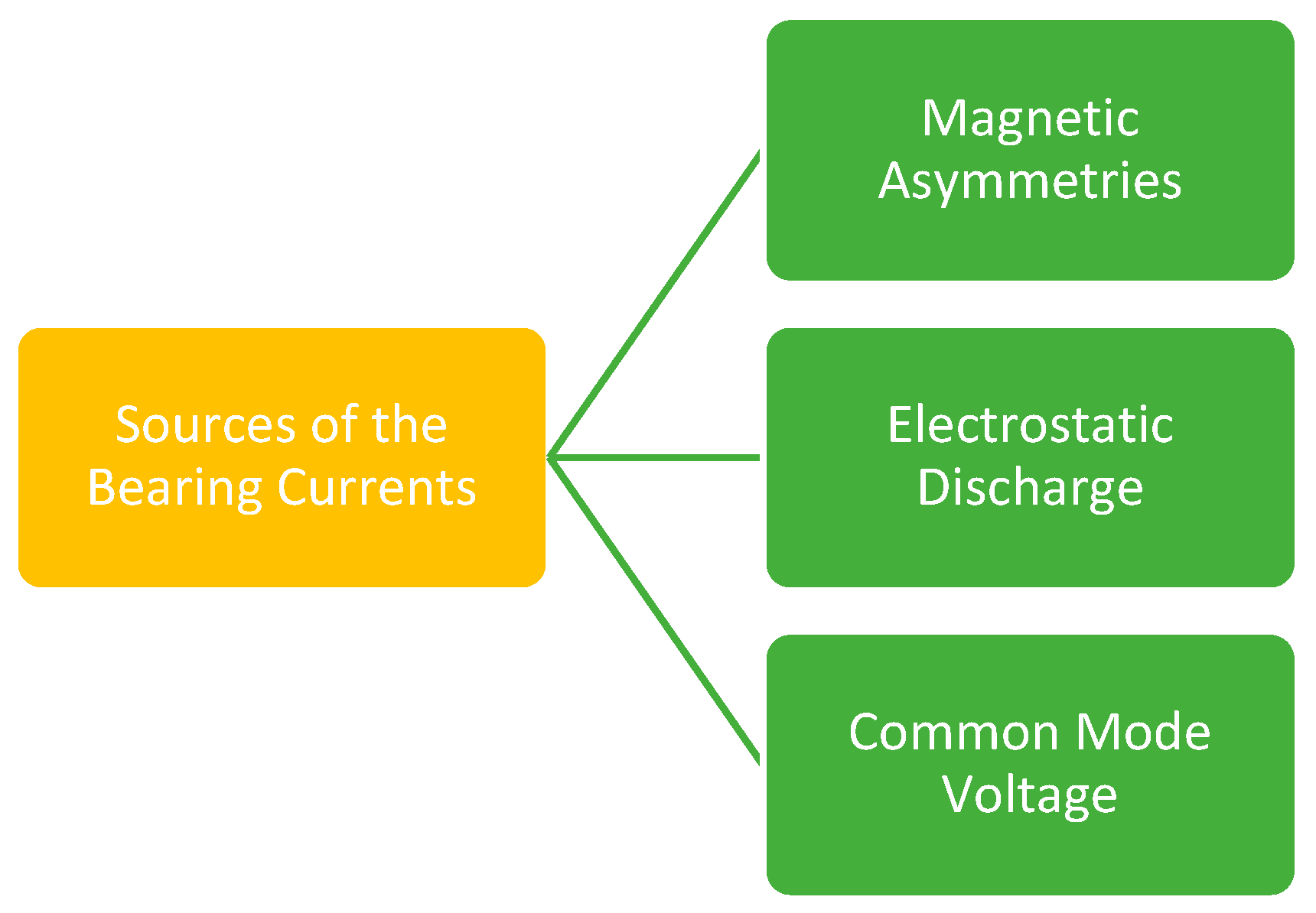
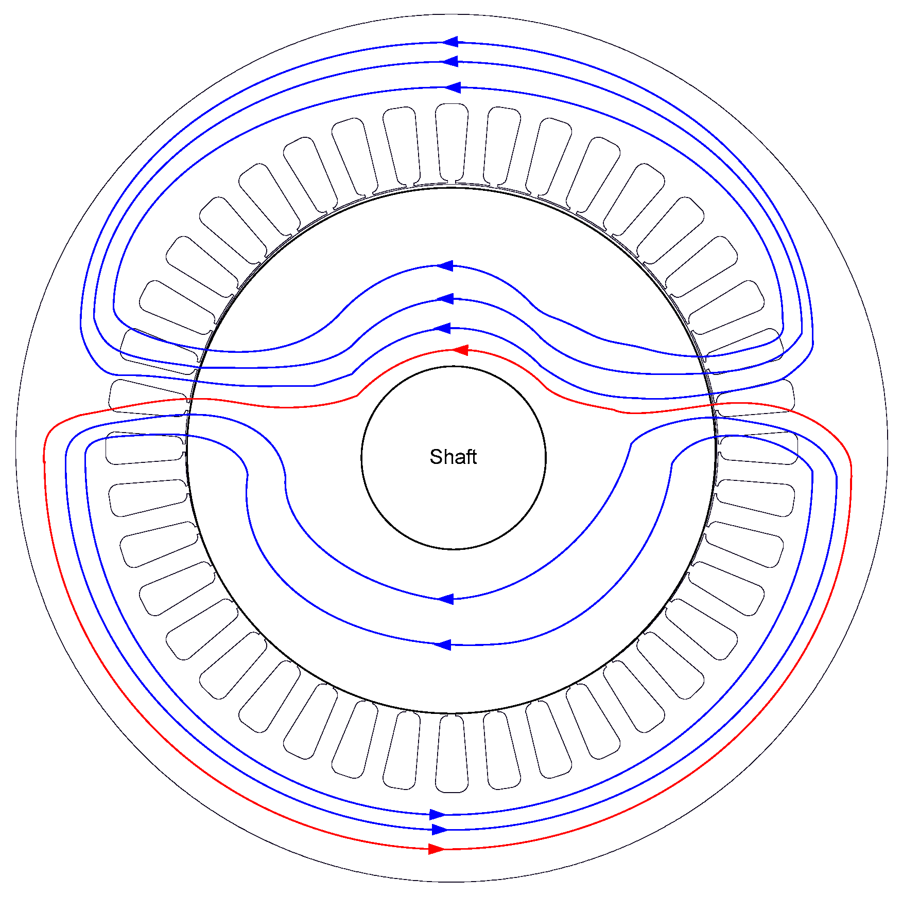
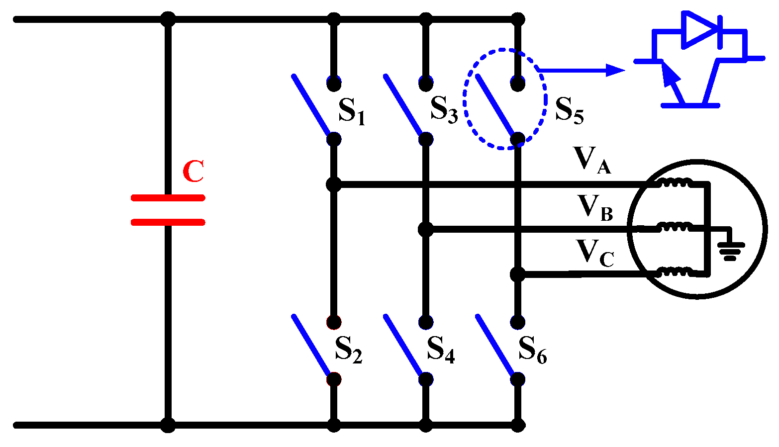
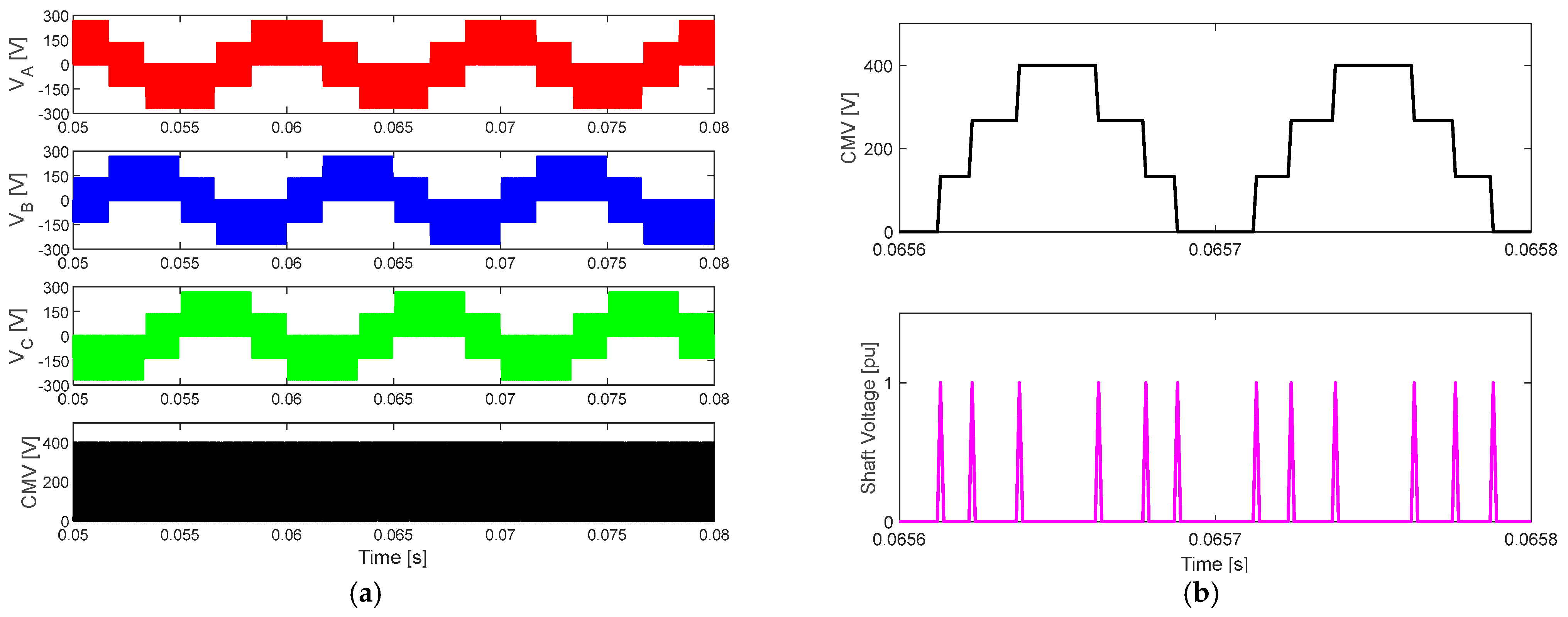
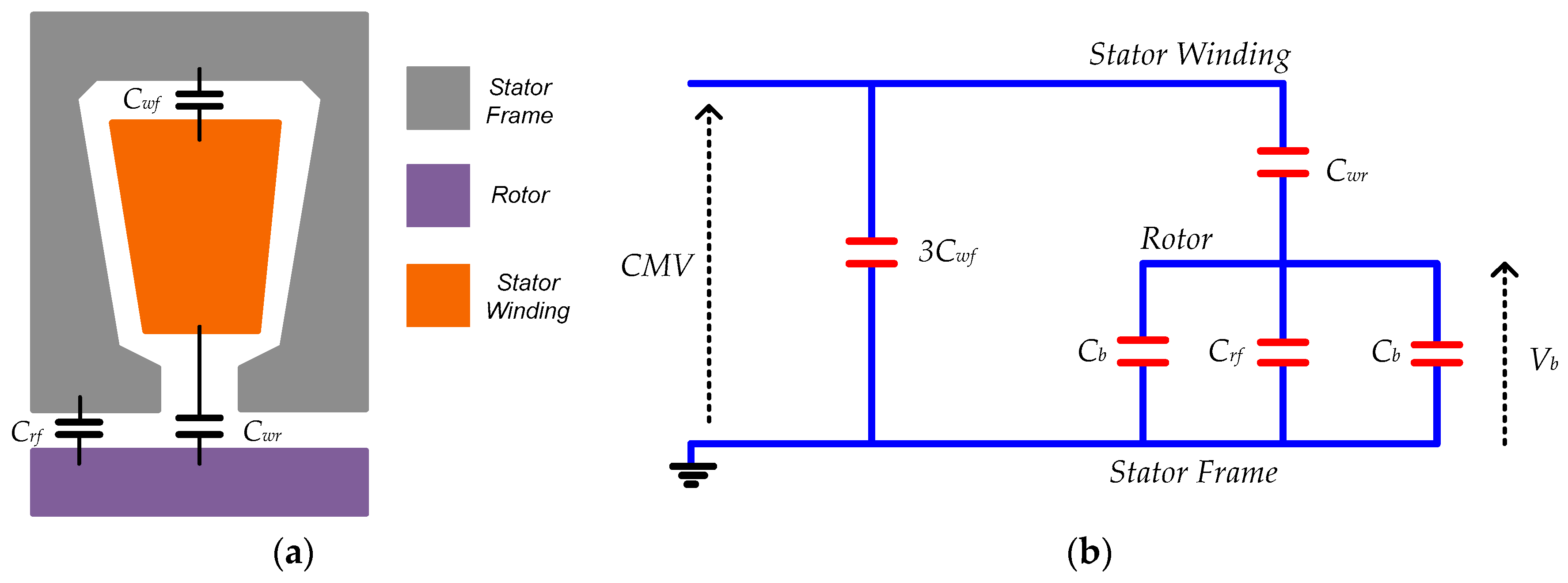
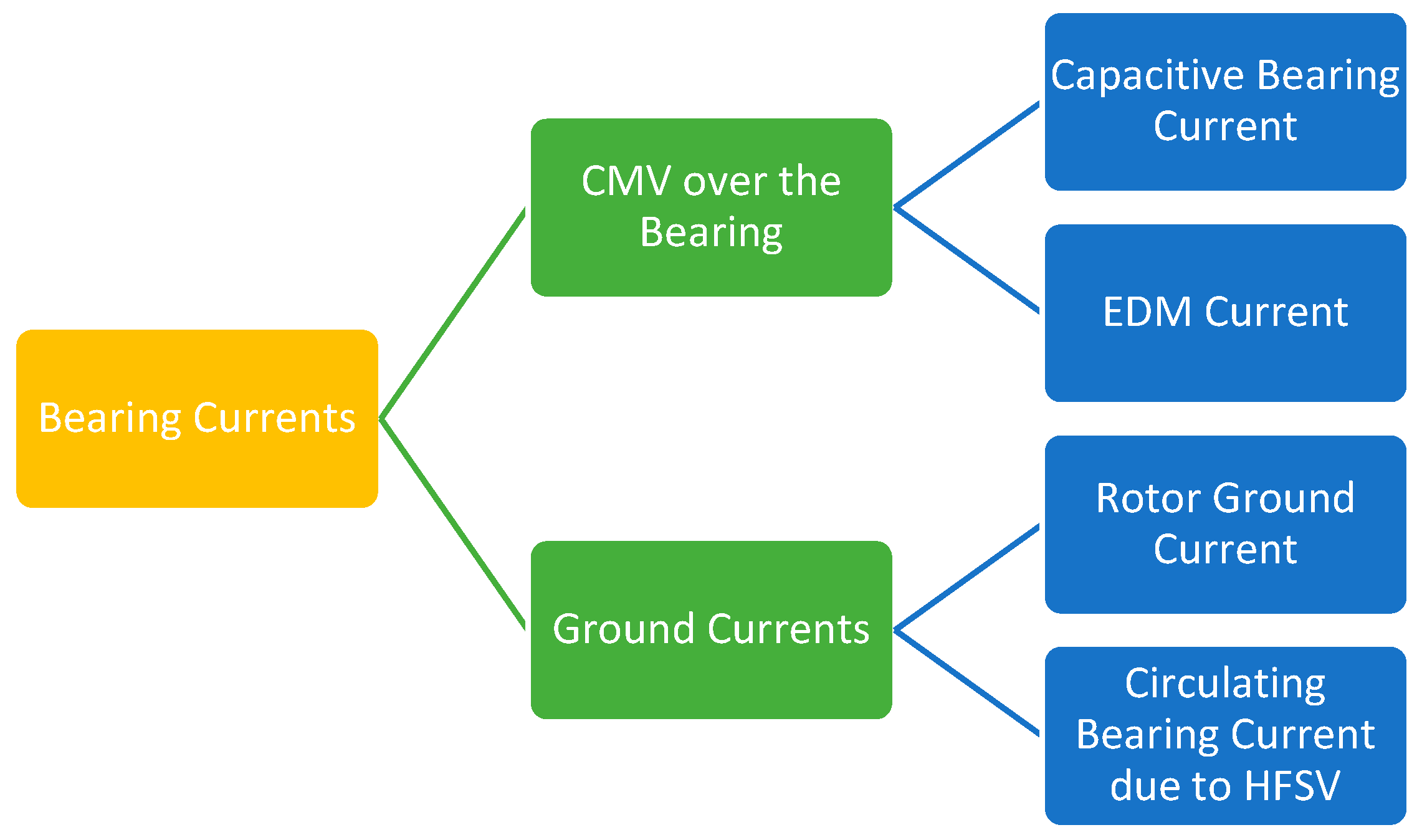
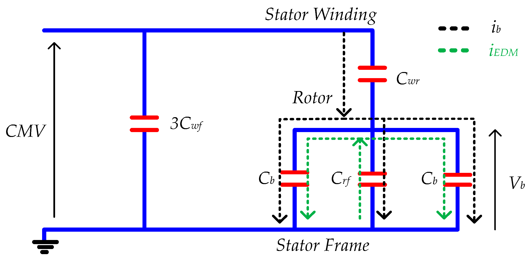
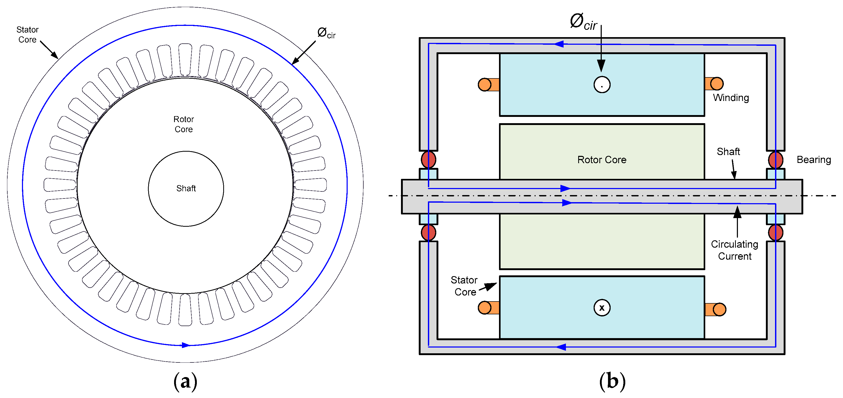
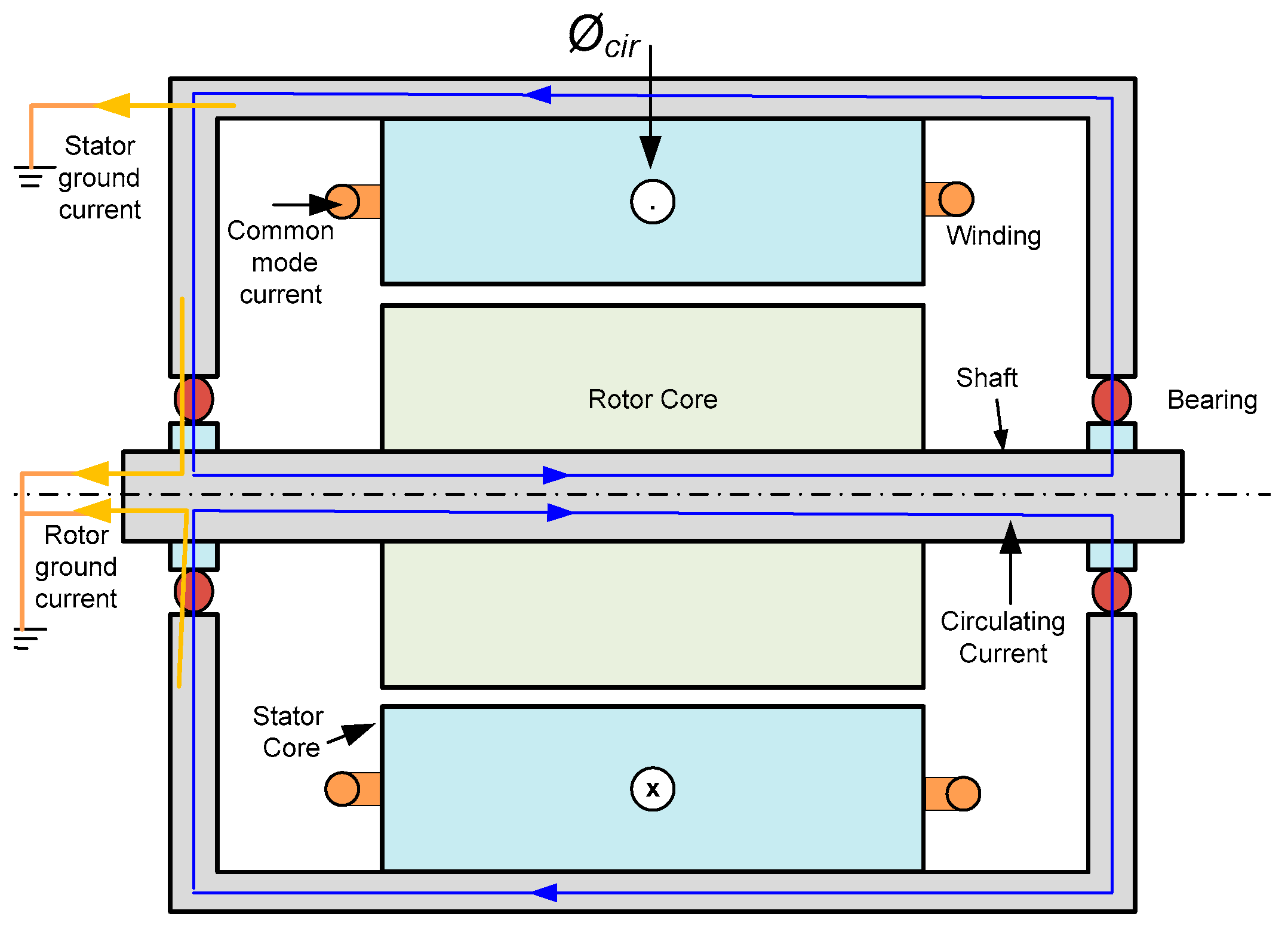
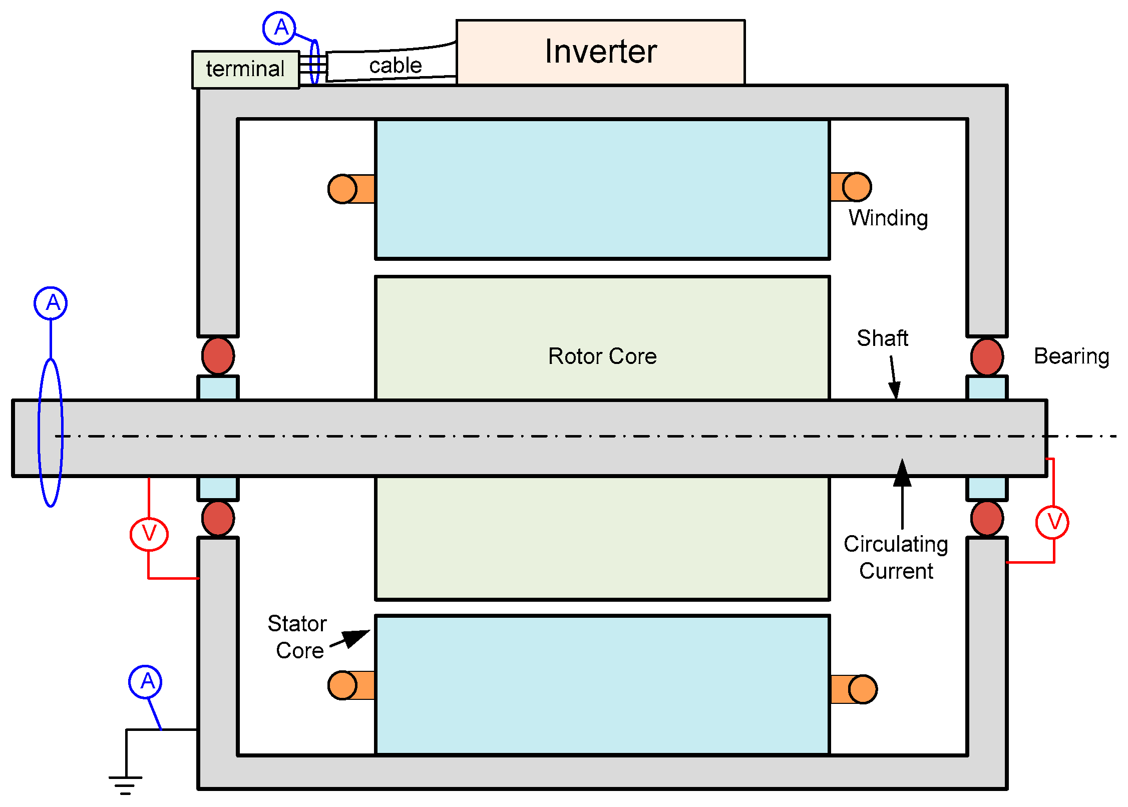
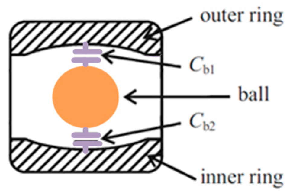
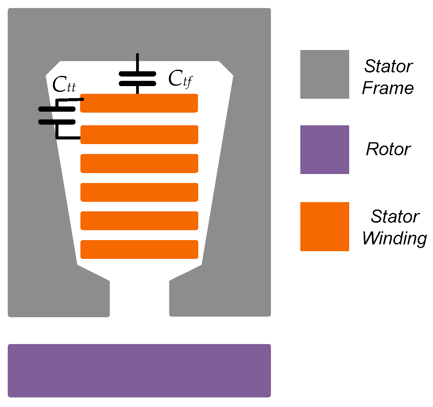
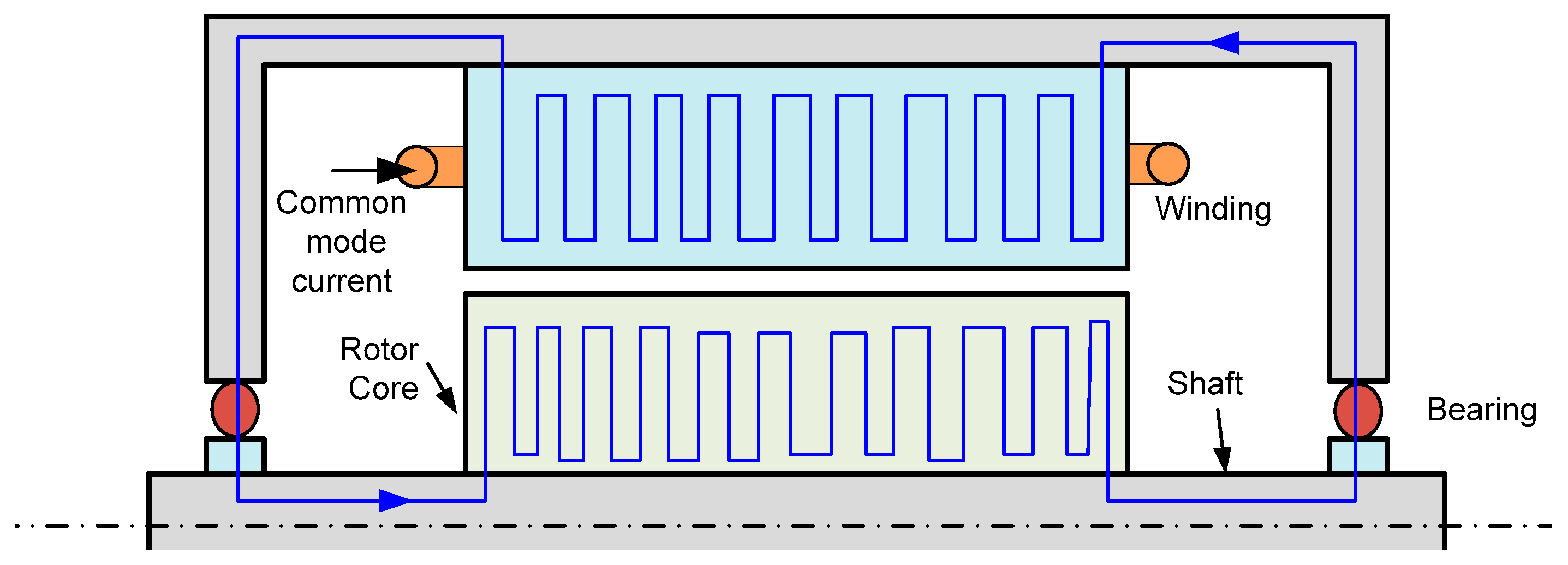
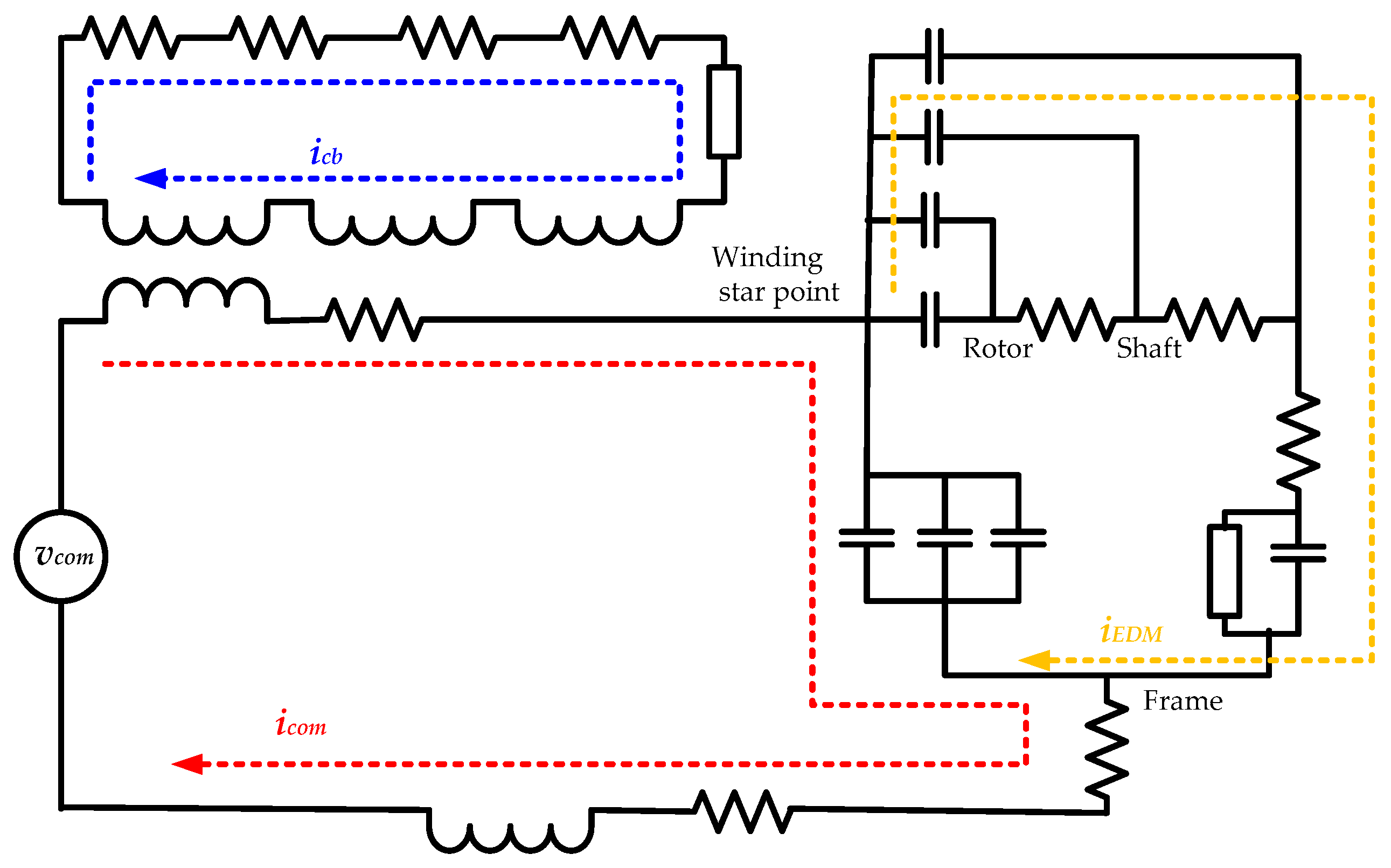
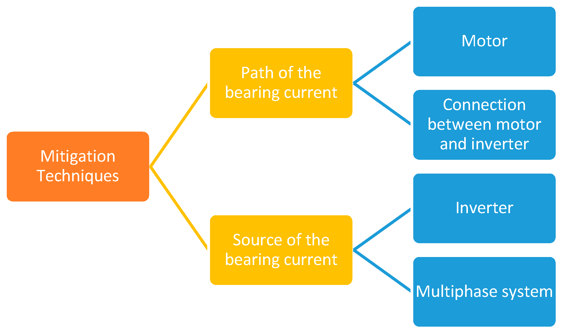
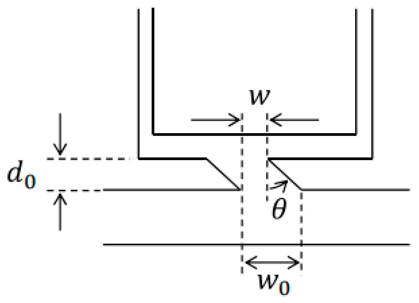
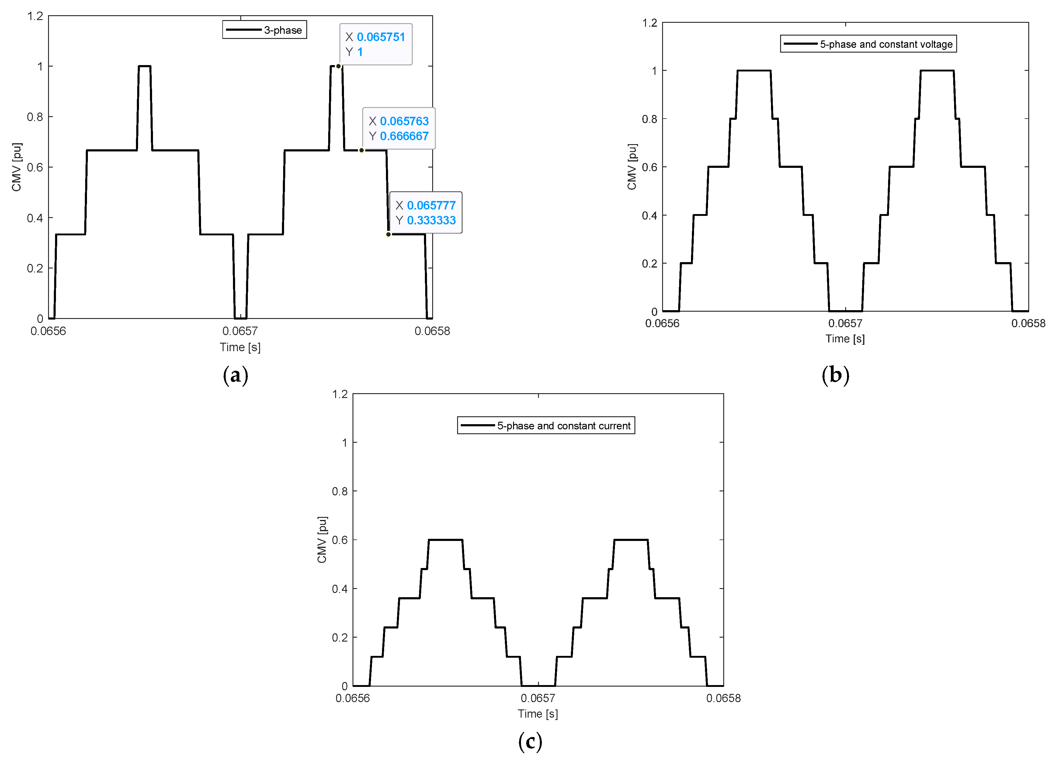
| Failure Mode | IEEE Study | EPRI Study | Average (%) | ||
|---|---|---|---|---|---|
| Failure Contribution | (%) | Failure Component | (%) | ||
| Mechanical failure | High vibration | 15.5 | Sleeve bearings | 16 | |
| Poor lubrication | 15.2 | Antifriction bearings | 8 | ||
| - | - | Trust bearings | 5 | ||
| - | - | Rotor shaft | 2 | ||
| - | - | Rotor core | 1 | ||
| Total | 30.7 | Total | 32 | 31.35 | |
| Electrical failure | Normal deterioration | 26.4 | Stator ground insulation | 23 | |
| Persistent overload | 4.2 | Turn insulation | 4 | ||
| - | - | Bracing | 3 | ||
| - | - | Cage | 5 | ||
| - | - | Core | 1 | ||
| Total | 30.6 | Total | 36 | 33.3 | |
| Environmental and other reasons | High ambient temperature | 3 | Bearing seals | 6 | |
| Abnormal moisture | 5.8 | Oil leakage | 3 | ||
| Abnormal voltage | 1.5 | Frame | 1 | ||
| Abnormal frequency | 0.6 | Wedge | 1 | ||
| Abrasive chemicals | 4.2 | - | - | ||
| Poor ventilation cooling | 3.9 | - | - | ||
| Other reasons | 19.7 | Other components | 21 | ||
| Total | 38.70 | Total | 32.00 | 35.35 | |
| Rogowski Coil | High-Frequency Voltage Probe | Radio Frequency Antenna | |
|---|---|---|---|
| EDM current | There is no detection. | Detection of events with a suitable threshold. | Detection of events with a suitable threshold. |
| Circulating current | This current can be detected if the coil is placed inside the machine. | There was no detection at the industrial stage. Lately, detection began at the research stage. | There was no detection at the industrial stage. Lately, detection began at the research stage. |
| Rotor ground current | This current can be detected if the coil is placed outside the machine. | There was no detection at the industrial stage. Lately, detection began at the research stage. | There was no detection at the industrial stage. Lately, detection began at the research stage. |
| Comment | Extremely intrusive. | Relatively intrusive Sensitive to electromagnetic interference. | Non-intrusive. Sensitive to electromagnetic interference. |
Table 3.
Comparative analysis of CMV and THD of current in different inverter topologies.
| Topology | Number of Switches | %THD (Ia, Ib, Ic) | Peak to Peak of CMV | dv of the CMV |
|---|---|---|---|---|
| Two-level inverter | 6 | 1.34, 1.34, 1.34 | /3 | |
| Three-level NPC | 12 | 0.62, 0.62, 0.62 | /4 | /6 |
| [138] | 7 | 1.38, 1.38, 1.38 | /3 | /3 |
| [141] | 7 | 1.38, 1.38, 1.38 | /3 | /3 |
| [143] | 8 | 1.34, 1.34, 1.34 | /3 | /3 |
| [140] | 8 | 1.34, 1.34, 1.34 | /3 | /3 |
| [142] | 8 | 1.34, 1.34, 1.34 | /3 | /3 |
| [145] | 8 | 1.38, 1.38, 1.38 | /3 | /3 |
| [144] | 8 | 1.34, 1.34, 1.34 | /3 | /3 |
| [154] | 8 | 1.34, 1.34, 1.34 | /3 | /3 |
| [155] | 8 | 1.87, 1.87, 1.87 | /3 | /3 |
| [152] | 8 | 0.98, 1.33, 1.33 | /3 | /6 |
Table 4.
Comparative analysis of CMV in three- and five-phase systems (in per unit and three-phase system is the reference).
Table 4.
Comparative analysis of CMV in three- and five-phase systems (in per unit and three-phase system is the reference).
| 3-Phase System | 5-Phase System with Constant Voltage | 5-Phase System with Constant Voltage | |
|---|---|---|---|
| DC voltage | 1.0 | 1.0 | 0.6 |
| Motor rated voltage | 1.0 | 1.0 | 0.6 |
| Motor rated current | 1.0 | 0.6 | 1.0 |
| Rated speed | 1.0 | 1.0 | 1.0 |
| Peak to peak CMV | 1.0 | 1.0 | 0.6 |
| dv/dt of CMV | 1.0 | 0.6 | 0.36 |
Disclaimer/Publisher’s Note: The statements, opinions and data contained in all publications are solely those of the individual author(s) and contributor(s) and not of MDPI and/or the editor(s). MDPI and/or the editor(s) disclaim responsibility for any injury to people or property resulting from any ideas, methods, instructions or products referred to in the content. |
© 2023 by the authors. Licensee MDPI, Basel, Switzerland. This article is an open access article distributed under the terms and conditions of the Creative Commons Attribution (CC BY) license (https://creativecommons.org/licenses/by/4.0/).
Share and Cite
MDPI and ACS Style
Tawfiq, K.B.; Güleç, M.; Sergeant, P. Bearing Current and Shaft Voltage in Electrical Machines: A Comprehensive Research Review. Machines 2023, 11, 550. https://doi.org/10.3390/machines11050550
AMA Style
Tawfiq KB, Güleç M, Sergeant P. Bearing Current and Shaft Voltage in Electrical Machines: A Comprehensive Research Review. Machines. 2023; 11(5):550. https://doi.org/10.3390/machines11050550
Chicago/Turabian StyleTawfiq, Kotb B., Mehmet Güleç, and Peter Sergeant. 2023. "Bearing Current and Shaft Voltage in Electrical Machines: A Comprehensive Research Review" Machines 11, no. 5: 550. https://doi.org/10.3390/machines11050550
Note that from the first issue of 2016, this journal uses article numbers instead of page numbers. See further details here.