
Integration of sEMG-Based Learning and Adaptive Fuzzy Sliding Mode Control for an Exoskeleton Assist-as-Needed Support System


Department of Mechanical Engineering, Wichita State University, Wichita, KS 67260, USA
*
Author to whom correspondence should be addressed.
Machines 2023, 11(7), 671; https://doi.org/10.3390/machines11070671
Submission received: 19 May 2023
/
Revised: 9 June 2023
/
Accepted: 18 June 2023
/
Published: 21 June 2023
(This article belongs to the Special Issue State-of-the-Art in Service and Rehabilitation Machines)
Abstract
:This paper presents an adaptive Fuzzy Sliding Mode Control approach for an Assist-as-Needed (AAN) strategy to achieve effective human–exoskeleton synergy. The proposed strategy employs an adaptive instance-based learning algorithm to estimate muscle effort, based on surface Electromyography (sEMG) signals. To determine and control the inverse dynamics of a highly nonlinear 4-degrees-of-freedom exoskeleton designed for upper-limb therapeutic exercises, a modified Recursive Newton-Euler Algorithm (RNEA) with Sliding Mode Control (SMC) was used. The exoskeleton position error and raw sEMG signal from the bicep’s brachii muscle were used as inputs for a fuzzy inference system to produce an output to adjust the sliding mode control law parameters. The proposed robust control law was simulated using MATLAB-Simulink, and the results showed that it could instantly adjust the necessary support, based on the combined motion of the human–exoskeleton system’s muscle engagement, while keeping the state trajectory errors and input torque bounded within rads and N.m, respectively.
1. Introduction
In recent years, rehabilitative exoskeletons have been researched, developed, and tested for providing aid to patients with muscular disorders [1]. Elderly patients who suffer from motor impairments and paralysis due to disorders such as stroke have increased the demand for rehabilitative exoskeletons [2]. Studies have shown that patients who undergo rehabilitation exercises that increase the intensity over time see more improvement in the recovery process [3]. As such, research has been conducted on rehabilitative exoskeletons that can provide a stable and repetitive therapy session that steadily increases in intensity. However, a proper interaction between the exoskeleton and the patient must be established to ensure an efficient and effective therapeutic intervention. A rehabilitative exoskeleton must have an active monitoring system that encourages patients to utilize their body’s muscles as opposed to simply relying on the exoskeleton to provide assistance; one common solution is to implement an Assist-as-Needed (AAN) strategy [4]. This approach uses feedback from the user to control the exoskeleton, and it only provides a certain level of assistance based on the patient’s needs and behaviors. This will encourage patients to perform the rehabilitation exercise by themselves and improve the recovery process.
The AAN strategy has been implemented by researchers with differing methods. One of these methods is the impedance control strategy [5], where a relationship between a desired position and a force is modeled with a mass-spring-damper system. Yang et al. [6] implemented this strategy in their work, where they sought to have a rehabilitative robot guide a human wrist along a planned trajectory in two planes in order to train the elbow and shoulder joints. In their work, the forces applied by the patient are estimated using the mass-spring-damper system relationship, which is then fed back to the control unit of the robot.
One limitation of such an approach is that different impedance parameters must be determined for each patient during a tuning process, depending on the severity of the user’s injuries. This implies longer rehabilitation sessions as the tuning and adaptation require training data. Other strategies implemented by researchers to estimate the amount of torque provided by the actuators within the joints include the adaptive Radial-Basis Function Network (RBFN) [7] and model predictive control [8]. RBFN is used to estimate the active torque provided by the fingers in a finger-exoskeleton system, based on the actual system configuration. In model predictive control, surface EMG (sEMG) is utilized to estimate the active torque at the elbow joint. Even though these methods provide a solution, the trials and time required to tune these strategies are not feasible for clinical trials. The majority of existing AAN algorithms have limitations such as relying on partial limb movement, predefined models, or therapist intervention [9,10]. Challenges arise due to the limited muscle activity and restricted ranges of motion observed in stroke patients, which affect the accuracy of personalized treatment and the speed of patient recovery. Moreover, depending solely on prior collected data can introduce bias and may not yield effective results. These factors, among others, have led most existing AAN algorithms to remain in the research and development phases.
The implementation of artificial intelligence into rehabilitative exoskeletons has offered a solution. Implementing a combination of sEMG and force control to measure muscle activity has shown to be effective in teaching rehabilitative exoskeletons how to predict user’s movements [11,12,13]. Stroke patients suffering from extreme cases of spasticity may not be able to produce strong muscle movement [13,14]. In such cases, the exoskeleton must be able to recognize the user’s intentions using small quantities of data. Patients’ weak muscle activity can be measured using sEMG signals, which are then converted to forces. Those forces are then compared to the forces measured by the actuators in the exoskeleton. From there, the actuators provide a certain amount of torque, just enough to assist the user.
Researchers have also explored implementing a fuzzy logic-based control strategy into their rehabilitative exoskeletons [15]. Fuzzy logic is a method of computing that is based on the idea of having multiple variations of an outcome, as opposed to a binary “true or false” Boolean logic [16]. For instance, a Boolean logic-based system will present two functions: True or False. Fuzzy logic, however, presents differing levels of truth: Completely False, Somewhat True, Probably True, Likely True, Absolutely True, etc. Depending on the data, the program will yield an outcome of varying degrees of “Truth” [16]. Fuzzy logic is useful when dealing with systems where the data are constantly changing and cannot easily be modeled. This makes it especially attractive when dealing with human behavior [17].
Since human behavior rarely follows a strict model, fuzzy logic can be useful in making rehabilitative exoskeletons adapt to the behavior of the patient and their specific needs. The behavior of the user should dictate how the exoskeleton operates, rather than the other way around [15]. Researchers often combine fuzzy logic with traditional means of control such as EMG or Proportional-Integral-Derivative (PID) controllers. Control systems, such as those employing electromyography (EMG) to discern the user’s actions, utilize fuzzy logic to determine the extent of support delivered by the exoskeleton [17].
Combining these two strategies allows these control systems to adapt to human behavior, which is often nonlinear and nonuniform [15]. As patients progress through their rehabilitation programs, they will likely require less assistance from the exoskeleton as time goes on [18]. Because of this, rehabilitative exoskeletons must be able to adapt to patients’ recovery progress and the level of assistance needed at a moment’s notice. Combining traditional methods of the AAN strategy with fuzzy logic is effective in creating adaptive exoskeletons that prioritize user rehabilitation, safety, and comfort [15,17]. Fuzzy logic also alleviates a common concern amongst patients that rehabilitative exoskeletons often feel as if the exoskeleton is dictating their movement [19].
Studies have shown that patients who adhere to exoskeleton rehabilitation programs experience improvement in their motor functions; adherence to these programs has been found to correlate with effective rehabilitation [18]. So long as the programs and exercises are safe, comfortable, engaging, and efficient, patients should expect improvements in performance and rehabilitation [20,21]. Research has also shown that personalized treatment based on a patient’s specific needs is most effective in rehabilitating patients [22,23].
However, despite rehabilitative exoskeletons demonstrating positive results for patients, adherence to these rehabilitation programs is low [24]. Several factors dictate whether or not a patient will participate in and finish a rehabilitative program. These include but are not limited to, lack of autonomy while wearing the exoskeleton, limits in completing tasks of daily living, pain while wearing the exoskeleton, or simply not feeling comfortable with wearing a robotic exoskeleton [25].
To ensure effective rehabilitation, medical exoskeleton developers must consider both efficient performance and overall user comfort [26]. Oftentimes, the two are interlinked, as patients who feel comfortable are better equipped to utilize the exoskeleton’s full capabilities [26,27]. Exoskeletons that provide a level of assistance that can adjust to a patient’s needs are in high demand for these reasons [22].
Patients have expressed concerns that wearing exoskeletons feels unnatural, describing the process as feeling more as if the exoskeleton was moving them, rather than them being in control [19]. This work offers a solution to these concerns, utilizing an AAN strategy through an adaptive sEMG-based muscle effort calculation.
In this study, a fuzzy inference system is employed to adjust the aggressiveness of a Sliding Mode Control Law, based on adaptive surface Electromyography (sEMG)-derived muscle effort. This adaptation allows for modifying the level of assistance provided by an exoskeleton, enabling users to experience more natural motion during rehabilitation exercises. The utilization of sEMG is justified by its correlation with the force or effort exerted by the muscles, as indicated by its root mean square. To address the variability of sEMG signals, an algorithm is proposed to estimate the current muscle effort with minimal training time. The key contributions of this work are: an assist-as-needed control strategy that dynamically updates the assistance according to the user’s requirements, and a dynamic assistance level that relies solely on current measurements from the system without the need for extensive training sessions.
The rest of this paper is organized as follows: in Section 2, a description and the mathematical model of the exoskeleton used for the study are presented. In Section 3, the low-level control law used to command the exoskeleton is stated. Section 4 presents the proposed algorithm to determine the level of muscle effort, as well as the AAN strategy and how it is used to modify the parameters of the low lever control law to obtain the desired behavior. The results of the application of the AAN proposed in Section 3 are exhibited in Section 4, as well as its findings. Lastly, the conclusion and future works of the study are presented in Section 6.
2. Description of the Exoskeleton
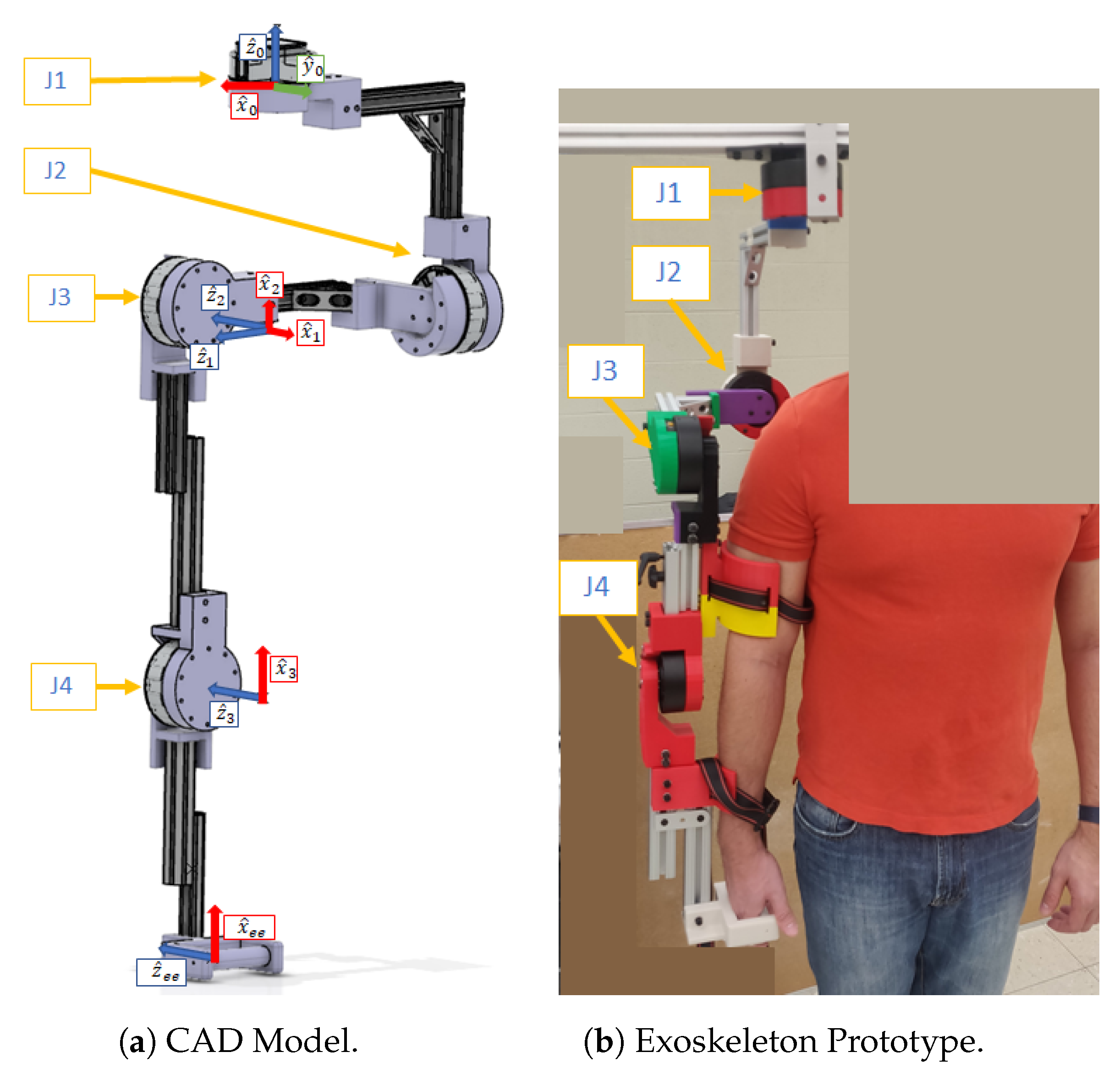
The exoskeleton (Figure 1) possesses four active revolute joints; three in the shoulder and one in the elbow. The shoulder joint is modeled using three intersecting axes. The elbow joint is modeled as a hinge joint, a 1-degree-of-freedom (DOF) revolute joint. The actuator used in each joint is an RMD-X8 Servo Motor with a nominal torque rating of 9 N.m. The kinematic model of the system is described using Denavit–Hartenberg (DH) parameters [28]. Reference joints with their frames are shown in Figure 1, and their respective DH parameters are given in Table 1.
The dynamics of the robot are represented by the following differential equation:
where is a generalized vector of joint coordinates, is the symmetric positive-definite mass matrix, is the coriolis and centripetal matrix, is the vector of forces due to gravity, is the Jacobian matrix, is the wrench of forces and moments applied on the environment from the robot at the end-effector coordinates, is the vector of torque and forces exerted by each joint, and n is the number of DOFs. Sometimes, it is more convenient to express the summation as . The dynamics of the robot can then be expressed in Equation (2).
The dynamics can be derived by using either the Euler-Lagrange method [29] or the Recursive Newton-Euler Algorithm (RNEA) [30]. Euler-Lagrange uses the kinetic and potential energy of the robot to obtain the equation of motion. Typically, it yields a simple set of equations. However, as the number of DOFs or joints increases, so does the complexity of the procedure. This makes it unfeasible for a multi-DOF rehabilitative exoskeleton. The RNEA method calculates each link’s twist (a spatial velocity vector containing linear and angular velocity) and each link’s wrench (a spatial force vector made of forces and moments). RNEA is computationally more efficient to implement for robots with many DOFs. Regardless of which method is used, the closed-form dynamic Equation (2) can be derived.
In this study, the Recursive Newton-Euler method is implemented. The implementation of this method is based on an algorithm having two different iterations, named the forward and backward iterations. In the forward iteration, given a robot with attached frames from the base to the end-effector and the actual configuration of the robot, for the twist of each link starting at the base frame, is calculated using Newton’s laws of motion. In the backward iteration, the wrench exerted on each link is calculated, starting at the end-effector and going backwards to the base frame. The actual configuration of the robot, the inertia matrices, , of each link, and the link masses, , are also required. These parameters need to be defined with respect to the local coordinate frame where the twist of each link is calculated. In [31], the implementation of this algorithm is explained in further detail. The presented algorithm is formulated using Spatial Vector Algebra, which is based on Plücker Coordinates [32]. With this representation, it is possible to combine the linear and rotational dynamics of a robot. The equation of motion of a single rigid body in spatial coordinates is presented in Equation (3).
where is the spatial velocity twist in Body b, is the screw vector in Body b coordinates that maps joint rates to joint velocities, is the spatial velocity of the parent of Body b but in b coordinates, is the spatial inertia matrix, is the transpose of the adjoint representation of , the bracket operator represents the skew symmetric matrix of a vector , and is the identity matrix. Given this information, the RNEA can be formulated as in Algorithm 1,
where the subscripts and refer to the parent and child of body i in i coordinates, respectively. The presented RNEA algorithm can be used to obtain different components of Equation (2). As an example, if the vector of the forces and torques is desired, then the inputs and are set as equal to 0.
| Algorithm 1: RNEA as in [31] |
Forward Iteration
Backward Iteration
|
Inertia Parameters of the Exoskeleton
3. Sliding Mode Control Law
The equation of motion of the robot yields a nonlinear system of differential equations; they must be linearized in order to apply linear time-invariant (LTI) control system strategies. One strategy used to linearize the robot’s dynamics is to use feedback linearization or computed-torque control (CTC) [31,33,34]. However, this approach assumes that the characteristics of the system are precisely known in order to cancel the nonlinear terms of the equation of motion of the system. This is highly unlikely in a real prototype of the system, due to manufacturing imperfections. Therefore, another control strategy that is robust with system uncertainties is preferred. Another control law strategy for nonlinear systems with such characteristics is Sliding Mode Control (SMC) [35,36]. This control law forces the state trajectories to reach and lie in a finite amount of time of some given function, usually called sliding surface, using a discontinuous decision function (switching gain). The stability of the SMC is guaranteed in the Lyapunov sense. The robustness of the SMC law makes it ideal for the control strategy for the four-joint exoskeleton presented in this work.
Control Law Derivation:
This work exploits the characteristics of the equation of the motion of a robot to derive the SMC law of the given system, as presented by Slotine in [35]. The mass matrix and the Coriolis matrix of Equation (2) are not independent; they are related by the constraint of . Since is symmetric, must be skew-symmetric [35,37]. The SMC law is derived using the candidate Lyapunov function , where is the vector of sliding surfaces, such that when , the control target is achieved. Therefore, the state trajectories are assured to converge to zero.
where is the trajectory error, is the desired state trajectory, can be viewed as a virtual desired velocity trajectory, and is a positive-definite matrix that contains the parameters that determine how fast the state trajectories reach the desired targets once they are on the sliding surfaces. Using Lyapunov’s stability criterion, for to reach zero, must be negative definite. Differentiating :
Solving for in (2) in substituting it in :
The control input is defined as to make , where is the best estimate of the robot dynamics and is the vector of the gains of components . Then, Equation (8) turns into Equation (10).
The gain vector K can be derived as follows:
where is a constant value that is greater than 0, , , and are the bounded uncertainties of the mass matrix, Coriolis matrix, and vectors of gravity and external forces, respectively.
In practice, the discontinuous sign function induces chattering in the control signal, which might excite the high-frequency dynamics of the system [38]. In order to avoid this, the discontinuous function must be smoothed out. One commonly used function to smooth the discontinuous term is the saturation function [35,39]. Applying the substitution to the control input yields Equation (12). Under this circumstance, the system will converge and stay within a boundary layer around the sliding surface; the width of the boundary layer depends on the variable . As a result, the chattering is controlled, but the tracking error is affected negatively.
4. A Proposed AAN Control Strategy
In this section, the proposed AAN control strategy is described. A Fuzzy Logic Controller (FLC) is proposed to increase or decrease the aggressiveness of the SMC law to reach the desired tracking trajectories. The positive-definite matrix in Equation (5) determines how exponentially fast the state trajectories, , will reach the desired trajectories, . This fact is exploited in this work to decrease how aggressive the SMC law will be around , creating a boundary region where the wearer needs to apply some effort in order to reduce the position error, . Therefore, two candidate inputs for the FLC are proposed, the current , and the effort being provided by the wearer. The former is obtained by subtracting the current joint positions by the target positions , and the latter is estimated by using an adaptive muscle effort algorithm based on sEMG. The proposed FLC yields the corresponding components of . For simplicity, in this work, is a diagonal matrix; this will allow us to control the SMC law aggressiveness for each one of the exoskeleton’s joints. The proposed closed-loop diagram for the presented ANN control strategy is shown in Figure 2. The inner loop of the control system consists of the Sliding Mode Control (SMC) law, which serves as the low-level control logic. It operates by comparing the desired trajectories with the actual state trajectories of the robot, resulting in the error dynamics, denoted as . On the other hand, the outer loop comprises the Fuzzy Logic Controller (FLC), which takes both the error dynamics of the system and the extracted muscle effort from the wearer’s muscle activities as inputs.
In the following subsections, the proposed strategy to estimate the muscle effort and the configuration of the FLC are presented.
4.1. Adaptive Muscle Effort Level Algorithm
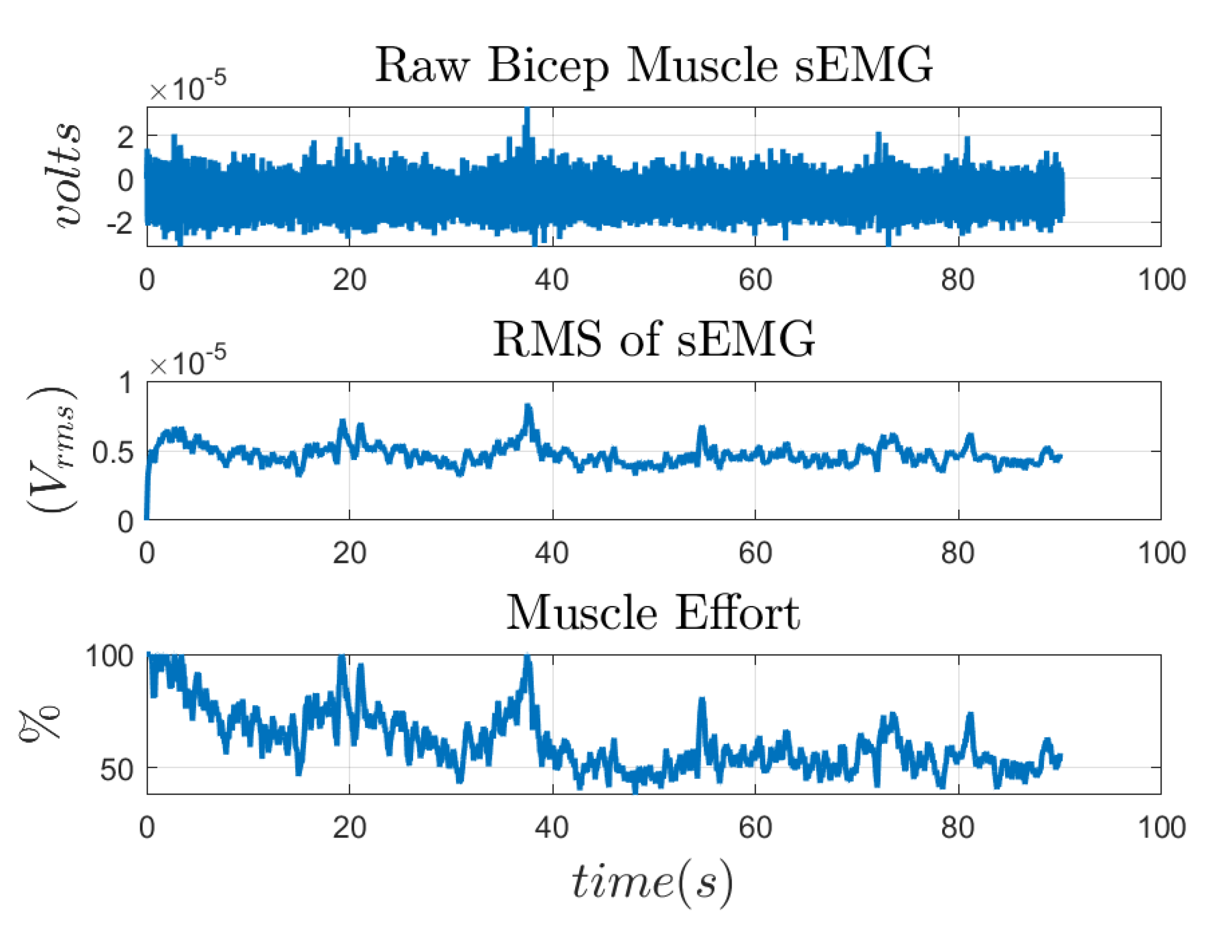
In this study, an instance-based adaptive muscle effort based on sEMG to calibrate the aggressiveness by which the SMC law changes the amount of torque provided by the exoskeleton’s joints is proposed. Usually, the exoskeleton is pre-programmed with a given routine—for example, elbow flexion—and then it carries the subject’s limb during the exercise. One drawback of this approach is that the subject may become dependent on the exoskeleton and may not put enough effort to complete the exercise; therefore, the recovery speed will be delayed. Thus, real-time user feedback is needed to adjust the amount of torque/force provided by the exoskeleton. In this work, we proposed to use sEMG to provide such feedback. Researchers commonly use the Root Mean Square (RMS) value of the sEMG, Equation (13), as an indicator of muscle health as it reflects the mean power of a signal [41].
In the current work, the elbow flexion exercise and the sEMG level of the bicep’s brachii muscle are selected for the implementation of the instance-based adaptive muscle effort as an input to a Fuzzy Inference System (FIS) to regulate the torque provided by the exoskeleton. There is evidence that there is a linear relationship between the RMS of the sEMG and the contraction force of the bicep brachii [42]. The proposed algorithm obtains the maximum RMS value of the first 10 s of data collection for sEMG from the subject’s muscle, while the robot performs the pre-programmed trajectory; this value is updated if, during the rest of the rehabilitation section, another maximum RMS calculation is found. Then, the muscle effort is updated as the ratio of the already found maximum RMS value with respect to the coming RMS calculations of the coming sEMG; Equation (14).
where and are the coming RMS calculations of the coming sEMG and the maximum RMS calculation of the current training section. An example of the proposed threshold calculation is shown in Figure 3.
By following this strategy, the muscle effort, , is the acceptable maximum effort (AME) and will always range from to . Furthermore, this strategy avoids the issue of obtaining the Maximum Voluntary Contraction (MVC) of a muscle since from the medical point of view, this quantity cannot be determined if a person is currently suffering from a disability [43].
4.2. Fuzzy SMC Law
In this work, a Mamdani FIS [44] is used to generate the component of that affects the SMC law output for joint 4 of the exoskeleton. This FIS is a nonlinear model that applies if-else statements or rules to produce an output that is based on qualitative knowledge instead of quantitative analysis. This means that it is not necessary to know the actual model of a physical system, but with enough experience on how it works, it is sufficient to generate control inputs to obtain a desired behavior. In our problem, perhaps it is desired to make the SMC law less aggressive if the position error, , and the muscle effort, are high, or perhaps if the current is too high, then the controller should be more aggressive independently of the muscle effort. Therefore, the Mamdani FIS model is suitable for our problem.
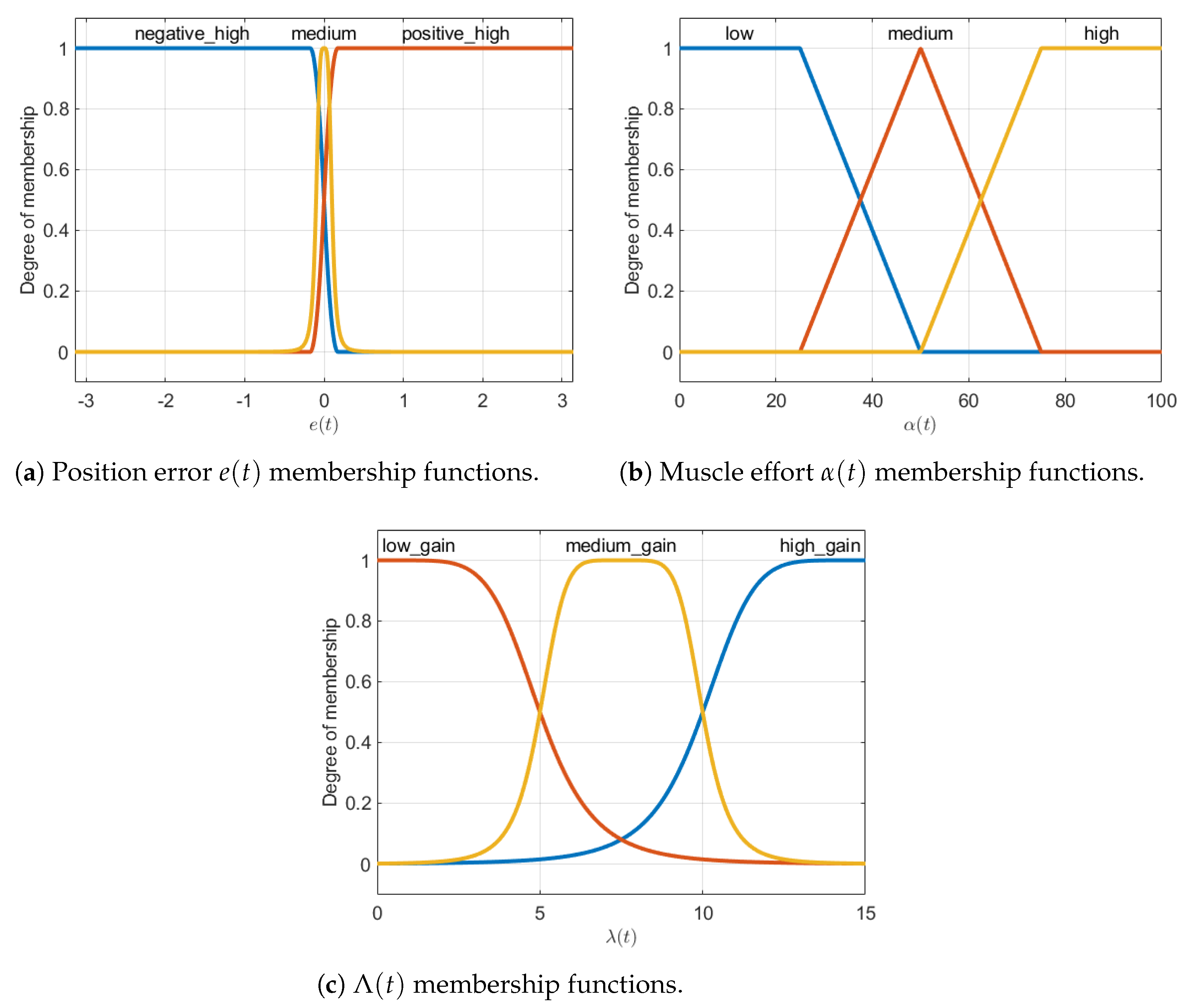
The configuration of the Mamdani FIS with two inputs and one output is made in MATLAB. The two inputs are defined as the position error, , and the muscle effort, , with a range of to and 0 to , respectively. On the other hand, the output is the component of matrix that affects joint 4 on the exoskeleton, which will be known as for the rest of the work, and it ranges from 0 to 15. Each input and the output are mapped into fuzzy sets using three membership functions for each; these functions are shown in Figure 4. For , its three membership functions are defined as a z-shape open to the left, and a bell-shape and s-shape open to the right for negative high, medium, and positive high values of position errors, respectively; Figure 4a. On the other hand, the membership functions for the input are defined as being trapezoidal, where each one of them represents low, medium, and high values of muscle effort; Figure 4b. Lastly, the membership functions of the output are defined as bell-shaped functions to represent low gain, medium gain, and high gain values; Figure 4c.
The if-then rules of the proposed FIS are based on the reasoning that the SMC law must be more or less aggressive, based on the current position error, and the muscle effort, is the following:
- If is positive high, then is high.
- If is negative high, then is high.
- If is medium and is high, then is low.
- If is medium and is medium, then is medium.
- If is medium and is low, then is high.
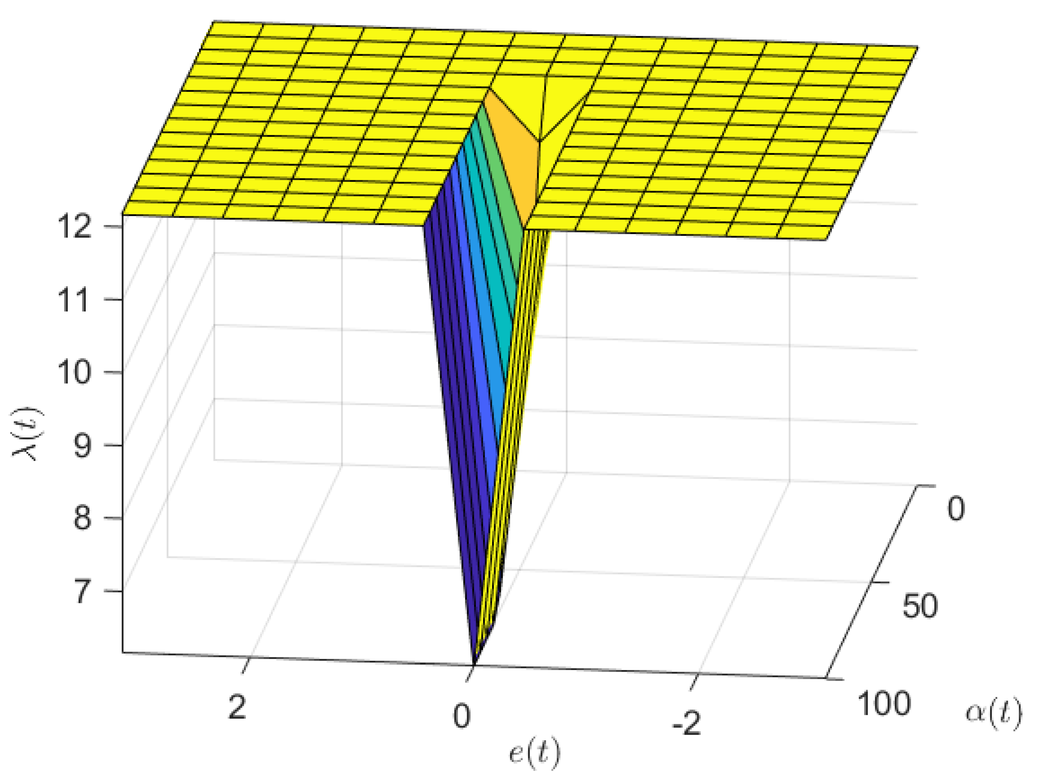
Based on the above if−then rules, the control surface that determines the value of given and is shown in Figure 5. From the figure, it is shown how the values of are saturated to 15 when the current error, , is outside of the allowable range of error independently of . On the other hand, if is maintained inside an allowable range, the value of changes with respect to and .
5. Results and Discussion
5.1. Implementation without Assistance
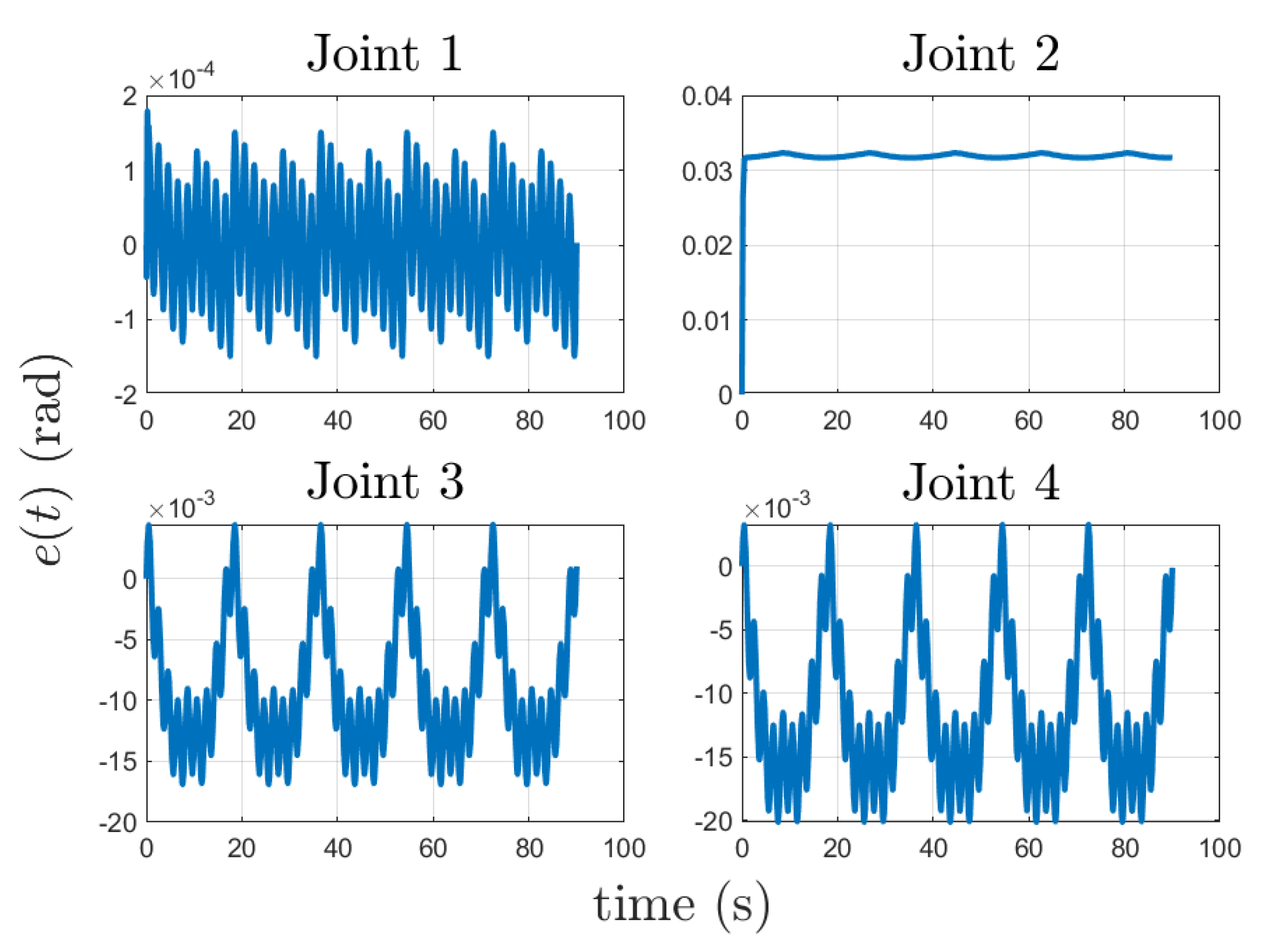
The SMC is implemented to verify its stability and to showcase the efficiency of the SMC law. The error dynamics of the state trajectories are bounded as established in Section 3. The system parameter uncertainty is . The parameters for the SMC are defined as the diagonal matrix , , and in the simulation to calculate the controller gain and the actual torque , using Equations (11) and (12), respectively. The desired trajectories, , are 0 for joints 1 through 3, and joint 4 will vary from 0 to . This motion follows a trapezoidal motion profile [31,45], with a maximum velocity and acceleration of 0.24 rad/s and 1 rad/s, respectively. The elbow flexion-extension motion is performed for approximately 90 s. Furthermore, a sinusoidal disturbance torque with an amplitude of 0.5 N.m with a period of 2 s is applied to joint 4. The implementation of the SMC was performed in Simulink and MATLAB; the simulation diagram is shown in Figure 6. The desired trajectory, , the error dynamics of each joint, , and the required input torques are shown in Figure 7, Figure 8 and Figure 9, respectively. From these results, it can be observed that the error dynamics given by are bounded. Specifically, the position error at joint 4 is bounded between and rads during the task, while requiring a feasible amount of bounded torque between −0.5 and 1.5 N.m.
5.2. Implementation with Assistance
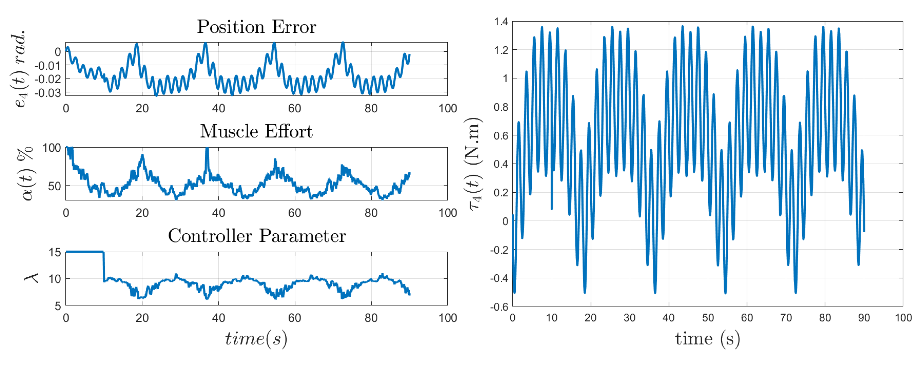
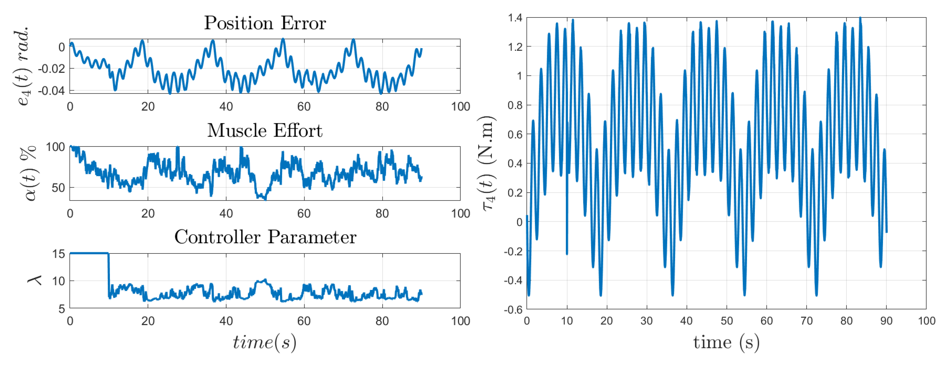
Surface EMG signals were collected from four healthy subjects aged between 18 and 25 years. The Delsys Trigno Wireless EMG system was used to collect data at a sampling rate of 2000 Hz. In order to avoid any artifact coming from the motion, the mean of the sEMG data was subtracted, since its mean value must be zero [43]. Additionally, the sEMG signal was filtered with a fifth-order Butterworth bandpass filter with cutoff frequencies at 20 Hz and 150 Hz. This process was performed before extracting the RMS value of the signal, defined by Equation (13). Then, simulations were performed as well with each individual sEMG information and with the FLC SMC Law. Figure 10, Figure 11, Figure 12 and Figure 13 show the inputs and outputs of the FIS for each subject, where each individual presents different levels of position error, muscle effort, and controller parameter . Subject 1, Figure 10, presented a muscle effort between the low and medium range, as well as an absolute value of the position error at joint 4 less than 0.04 rad, which is considered as a medium value; as result, the controller parameter was maintained in the medium range. A similar result can be inferred from subject 2, Figure 11. In this case, there are low peaks on the controller parameter due to the high values of muscle effort . For subject 3, Figure 12, the controller parameter was maintained on the low range, since most of the time, the subject presented a medium to high firing activity on while maintaining the position error in the medium range. Lastly, Subject 4, Figure 13, presented similar results as Subject 3.
In addition, the control input torque for joint 4 has presented feasible values, which can be achieved by the servo motor presented in Section 2. The torque input values account for a range from N.m to 1.4 N.m, and the torque curve did not present undesirable chattering, which is desirable.
6. Conclusions and Future Work
In this study, an adaptive muscle effort based on sEMG that serves as an input to a fuzzy inference system that modifies the aggressiveness of the SMC law that controls the exoskeleton was provided. The proposed control was used as an Assist-as-Needed (AAN) control strategy to provide assistance to a wearer while performing an elbow flexion task while adapting its parameters, based on the current joint position error and subject-varying muscle effort. The results showed that the controller was capable of maintaining the position error bound for each subject while requiring feasible torque inputs. Additionally, it demonstrates its usefulness for this type of application, where different subjects can wear the exoskeleton for rehabilitation, and it can automatically adjust itself to provide assistance without needing long training sections to train an algorithm. Future works will explore the involvement of other muscles on different joints of the upper arm such as the shoulder, in order to feed the proposed fuzzy SMC Law.
Author Contributions
Conceptualization, P.D. and Y.Y.; methodology, P.D. and Y.Y.; software, P.D.; validation, P.D. and Y.Y.; formal analysis, P.D.; investigation, P.D., N.G. and Y.Y.; resources, Y.Y.; data curation, P.D.; writing—original draft preparation, P.D.; writing—review and editing, N.G. and Y.Y.; supervision, Y.Y.; funding acquisition, Y.Y. All authors have read and agreed to the published version of the manuscript.
Funding
This work was supported by the National Science Foundation under grant no. CBET-1915872. The content is solely the authors’ responsibility.
Data Availability Statement
Data are available upon request.
Conflicts of Interest
The authors declare no conflict of interest.
Special Symbols
The following Special Symbols are used in this manuscript:
| Vector of torque and forces exerted by joints | |
| Sliding surfaces vector | |
| Positive-definite matrix of decaying exponential rate of the state trajectory errors | |
| Decaying exponential rate of the state trajectory error | |
| Signum operation | |
| Saturation operation | |
| Boundary layer value to smooth out the switching operation in the SMC | |
| Current surface EMG values | |
| Current maximum surface EMG values | |
| Calculated muscle effort |
References
- Krebs, H.; Volpe, B.; Aisen, M.; Hogan, N. Increasing productivity and quality of care: Robot-aided neuro-rehabilitation. J. Rehabil. Res. Dev. 2000, 37, 639–652. [Google Scholar] [PubMed]
- Benjamin, E.J.; Blaha, M.J.; Chiuve, S.E.; Cushman, M.; Das, S.R.; Deo, R.; Floyd, J.; Fornage, M.; Gillespie, C.; Isasi, C.; et al. Heart disease and stroke statistics-2017 update: A report from the American Heart Association. Circulation 2017, 135, e146–e603. [Google Scholar]
- Klamroth-Marganska, V.; Blanco, J.; Campen, K.; Curt, A.; Dietz, V.; Ettlin, T.; Felder, M.; Fellinghauer, B.; Guidali, M.; Kollmar, A.; et al. Three-dimensional, task-specific robot therapy of the arm after stroke: A multicentre, parallel-group randomised trial. Lancet Neurol. 2014, 13, 159–166. [Google Scholar] [CrossRef] [PubMed]
- Cai, L.L.; Fong, A.J.; Liang, Y.; Burdick, J.; Edgerton, V.R. Assist-as-needed training paradigms for robotic rehabilitation of spinal cord injuries. In Proceedings of the 2006 IEEE International Conference on Robotics and Automation (ICRA 2006), Orlando, FL, USA, 15–19 May 2006; pp. 3504–3511. [Google Scholar]
- Hogan, N. Impedance control: An approach to manipulation: Part I—Theory. J. Dyn. Syst. Meas. Control 1985, 107, 1–7. [Google Scholar] [CrossRef]
- Yang, Y.; Wang, L.; Tong, J.; Zhang, L. Arm rehabilitation robot impedance control and experimentation. In Proceedings of the 2006 IEEE International Conference on Robotics and Biomimetics, Kunming, China, 17–20 December 2006; pp. 914–918. [Google Scholar]
- Agarwal, P.; Deshpande, A.D. Subject-specific assist-as-needed controllers for a hand exoskeleton for rehabilitation. IEEE Robot. Autom. Lett. 2017, 3, 508–515. [Google Scholar] [CrossRef]
- Teramae, T.; Noda, T.; Morimoto, J. EMG-based model predictive control for physical human–robot interaction: Application for assist-as-needed control. IEEE Robot. Autom. Lett. 2017, 3, 210–217. [Google Scholar] [CrossRef]
- Mehdi, H.; Boubaker, O. Stiffness and impedance control using Lyapunov theory for robot-aided rehabilitation. Int. J. Soc. Robot. 2012, 4, 107–119. [Google Scholar] [CrossRef]
- George, J.A.; Gunnell, A.J.; Archangeli, D.; Hunt, G.; Ishmael, M.; Foreman, K.B.; Lenzi, T. Robust torque predictions from electromyography across multiple levels of active exoskeleton assistance despite non-linear reorganization of locomotor output. Front. Neurorobot. 2021, 15, 700823. [Google Scholar] [CrossRef]
- Vélez-Guerrero, M.A.; Callejas-Cuervo, M.; Mazzoleni, S. Artificial intelligence-based wearable robotic exoskeletons for upper limb rehabilitation: A review. Sensors 2021, 21, 2146. [Google Scholar] [CrossRef]
- Fleischer, C.; Wege, A.; Kondak, K.; Hommel, G. Application of EMG Signals for Controlling Exoskeleton Robots; Walter de Gruyter: New York, NY, USA, 2006. [Google Scholar]
- Hameed, H.K.; Hassan, W.Z.W.; Shafie, S.; Ahmad, S.A.; Jaafar, H. A review on surface electromyography-controlled hand robotic devices used for rehabilitation and assistance in activities of daily living. JPO J. Prosthetics Orthot. 2020, 32, 3–13. [Google Scholar] [CrossRef]
- Lambelet, C.; Lyu, M.; Woolley, D.; Gassert, R.; Wenderoth, N. The eWrist—A wearable wrist exoskeleton with sEMG-based force control for stroke rehabilitation. In Proceedings of the 2017 International Conference on Rehabilitation Robotics (ICORR), London, UK, 17–20 July 2017; pp. 726–733. [Google Scholar]
- Zhong, B.; Cao, J.; Guo, K.; McDaid, A.; Peng, Y.; Miao, Q.; Xie, S.; Zhang, M. Fuzzy logic compliance adaptation for an assist-as-needed controller on the Gait Rehabilitation Exoskeleton (GAREX). Robot. Auton. Syst. 2020, 133, 103642. [Google Scholar]
- Fuzzy logic systems for engineering: A tutorial. Proc. IEEE 1995, 83, 345–377. [CrossRef] [Green Version]
- Al Rezage, G.; Tokhi, M. Fuzzy PID control of lower limb exoskeleton for elderly mobility. In Proceedings of the 2016 IEEE International Conference on Automation, Quality and Testing, Robotics (AQTR), Cluj-Napoca, Romania, 19–21 May 2016; pp. 1–6. [Google Scholar]
- Louie, D.R.; Mortenson, W.B.; Durocher, M.; Schneeberg, A.; Teasell, R.; Yao, J.; Eng, J.J. Efficacy of an exoskeleton-based physical therapy program for non-ambulatory patients during subacute stroke rehabilitation: A randomized controlled trial. J. Neuroeng. Rehabil. 2021, 18, 1–12. [Google Scholar]
- Vaughan-Graham, J.; Brooks, D.; Rose, L.; Nejat, G.; Pons, J.; Patterson, K. Exoskeleton use in post-stroke gait rehabilitation: A qualitative study of the perspectives of persons post-stroke and physiotherapists. J. Neuroeng. Rehabil. 2020, 17, 1–15. [Google Scholar]
- Chen, H.; Ou, H.; Chen, H. A Method for Rehabilitation of Hand Dysfunction by Cyber Glove. In Proceedings of the 2015 International Conference on Advanced Engineering Materials and Technology, Guangzhou, China, 22–23 August 2015; Atlantis Press: Paris, France, 2015; pp. 393–396. [Google Scholar]
- Mocan, M.; Vlaicu, S.I.; Farcaș, A.D.; Feier, H.; Dragan, S.; Mocan, B. Cardiac rehabilitation early after sternotomy using new assistive VR-enhanced robotic exoskeleton—study protocol for a randomised controlled trial. Int. J. Environ. Res. Public Health 2021, 18, 11922. [Google Scholar] [PubMed]
- Qian, Z.; Bi, Z. Recent development of rehabilitation robots. Adv. Mech. Eng. 2015, 7, 563062. [Google Scholar]
- Pan, Y.T.; Kang, I.; Joh, J.; Kim, P.; Herrin, K.R.; Kesar, T.M.; Sawicki, G.S.; Young, A.J. Effects of bilateral assistance for hemiparetic gait post-stroke using a powered hip exoskeleton. Ann. Biomed. Eng. 2023, 51, 410–421. [Google Scholar]
- Graf, E.; Wirz, M.; Pauli, C.; Bauer, C. Ankle kinematics during walking with a soft exoskeleton in people with dropfoot–a case series. In Proceedings of the XXVIII Congress of the International Society of Biomechanics, Online, 25–29 July 2021. [Google Scholar]
- Chiș, L.C.; Copotoiu, M.; Moldovan, L. Different types of exoskeletons can improve the life of spinal cord injury’s patients—A meta-analysis. Procedia Manuf. 2020, 46, 844–849. [Google Scholar]
- Du Plessis, T.; Djouani, K.; Oosthuizen, C. A review of active hand exoskeletons for rehabilitation and assistance. Robotics 2021, 10, 40. [Google Scholar]
- Sarkisian, S.V.; Ishmael, M.K.; Lenzi, T. Self-aligning mechanism improves comfort and performance with a powered knee exoskeleton. IEEE Trans. Neural Syst. Rehabil. Eng. 2021, 29, 629–640. [Google Scholar] [CrossRef]
- Denavit, J.; Hartenberg, R.S. A kinematic notation for lower-pair mechanisms based on matrices. J. Appl. Mech. 1955, 22, 215–221. [Google Scholar]
- Zefran, M.; Bullo, F. Lagrangian dynamics. In Robotics and Automation Handbook; Citeseer: Gaithersburg, MD, USA, 2005; pp. 5–1. [Google Scholar]
- Khalil, W. Dynamic modeling of robots using newton-euler formulation. In Informatics in Control, Automation and Robotics; Springer: Berlin/Heidelberg, Germany, 2011; pp. 3–20. [Google Scholar]
- Lynch, K.M.; Park, F.C. Modern Robotics; Cambridge University Press: Cambridge, MA, USA, 2017. [Google Scholar]
- Featherstone, R. Plucker basis vectors. In Proceedings of the 2006 IEEE International Conference on Robotics and Automation (ICRA 2006), Orlando, FL, USA, 15–19 May 2006; pp. 1892–1897. [Google Scholar]
- Kelly, R.; Davila, V.S.; Loría, A. Computed-Torque Control and Computed-Torque+ Control. In Control of Robot Manipulators in Joint Space; Springer: London, UK, 2005; pp. 227–241. [Google Scholar]
- Ullah, M.I.; Ajwad, S.A.; Islam, R.U.; Iqbal, U.; Iqbal, J. Modeling and computed torque control of a 6 degree of freedom robotic arm. In Proceedings of the 2014 International Conference on Robotics and Emerging Allied Technologies in Engineering (iCREATE), Islamabad, Pakistan, 22–24 April 2014; pp. 133–138. [Google Scholar]
- Slotine, J.J.E.; Li, W. Applied Nonlinear Control; Prentice Hall Englewood Cliffs: Hoboken, NJ, USA, 1991; Volume 199. [Google Scholar]
- Edwards, C.; Spurgeon, S. Sliding Mode Control: Theory and Applications; CRC Press: Boca Raton, FL, USA, 1998. [Google Scholar]
- Slotine, J.J.E.; Li, W. On the adaptive control of robot manipulators. Int. J. Robot. Res. 1987, 6, 49–59. [Google Scholar]
- Young, K.D.; Utkin, V.I.; Ozguner, U. A control engineer’s guide to sliding mode control. IEEE Trans. Control Syst. Technol. 1999, 7, 328–342. [Google Scholar]
- Rahman, M.H.; Saad, M.; Kenné, J.P.; Archambault, P.S. Control of an exoskeleton robot arm with sliding mode exponential reaching law. Int. J. Control Autom. Syst. 2013, 11, 92–104. [Google Scholar]
- Echeandia, S.; Wensing, P.M. Numerical methods to compute the coriolis matrix and christoffel symbols for rigid-body systems. J. Comput. Nonlinear Dyn. 2021, 16, 091004. [Google Scholar]
- Sabut, S.K.; Sikdar, C.; Kumar, R.; Mahadevappa, M. Improvement of gait & muscle strength with functional electrical stimulation in sub-acute & chronic stroke patients. In Proceedings of the 2011 Annual International Conference of the IEEE Engineering in Medicine and Biology Society, Boston, MA, USA, 30 August–3 September 2011; pp. 2085–2088. [Google Scholar]
- Fukuda, T.Y.; Echeimberg, J.O.; Pompeu, J.E.; Lucareli, P.R.G.; Garbelotti, S.; Gimenes, R.O.; Apolinário, A. Root mean square value of the electromyographic signal in the isometric torque of the quadriceps, hamstrings and brachial biceps muscles in female subjects. J. Appl. Res. 2010, 10, 32–39. [Google Scholar]
- Konrad, P. The abc of emg. In A Practical Introduction to Kinesiological Electromyography; Noraxon Inc.: Scottsdale, AZ, USA, 2005; Volume 1, pp. 30–35. [Google Scholar]
- Mamdani, E.H.; Assilian, S. An experiment in linguistic synthesis with a fuzzy logic controller. Int. J.-Man-Mach. Stud. 1975, 7, 1–13. [Google Scholar]
- Heo, H.J.; Son, Y.; Kim, J.M. A trapezoidal velocity profile generator for position control using a feedback strategy. Energies 2019, 12, 1222. [Google Scholar]
Figure 1.
Four-Joint Exoskeleton.

Figure 2.
Closed-loop diagram of the proposed AAN Control Strategy.

Figure 3.
Instance−based adaptive muscle effort based on sEMG for the bicep muscle during a 90 s session of elbow flexion.
Figure 3.
Instance−based adaptive muscle effort based on sEMG for the bicep muscle during a 90 s session of elbow flexion.

Figure 4.
Input and output membership functions for the Fuzzy Inference System.

Figure 5.
Control surface for the Fuzzy Inference System, based on the input and output membership functions.
Figure 5.
Control surface for the Fuzzy Inference System, based on the input and output membership functions.

Figure 6.
Simulation Diagram of the System in Simulink, MATLAB.

Figure 7.
Desired trajectory, (a) and (b) .

Figure 8.
Error dynamics, , during the Elbow Flexion-Extension Exercise.

Figure 9.
Required Torque, , during the Elbow Flexion-Extension Exercise.

Figure 10.
Joint 4 position error and Torque, adaptive sEMG-Based Effort, and Controller Parameter for subject 1.
Figure 10.
Joint 4 position error and Torque, adaptive sEMG-Based Effort, and Controller Parameter for subject 1.

Figure 11.
Joint 4 position error and Torque, adaptive sEMG-Based Effort, and Controller Parameter for subject 2.
Figure 11.
Joint 4 position error and Torque, adaptive sEMG-Based Effort, and Controller Parameter for subject 2.

Figure 12.
Joint 4 position error and Torque, adaptive sEMG-Based Effort, and Controller Parameter for subject 3.
Figure 12.
Joint 4 position error and Torque, adaptive sEMG-Based Effort, and Controller Parameter for subject 3.

Figure 13.
Joint 4 position error and Torque, adaptive sEMG-Based Effort, and Controller Parameter for subject 4.
Figure 13.
Joint 4 position error and Torque, adaptive sEMG-Based Effort, and Controller Parameter for subject 4.


Table 1.
DH Parameter Table.
| Link | ||||
|---|---|---|---|---|
| 1 | 0 | −0.275 | ||
| 2 | 0 | 0 | ||
| 3 | −0.413 | 0 | 0 | |
| 4 | −0.297 | 0 | 0 |
Table 2.
Inertia Parameters, expressed in kg and kg· m.
| Link | 1 | 2 | 3 | 4 |
|---|---|---|---|---|
| Mass | 1.398 | 1.264 | 1.306 | 0.425 |
| Ixx | 0.076 | 0.013 | 0.028 | 0.008 |
| Iyy | 0.165 | 0.035 | 0.198 | 0.029 |
| Izz | 0.089 | 0.023 | 0.172 | 0.022 |
| Ixy | 0.0002 | 0.002 | 0.008 | 0.002 |
| Ixz | −0.078 | −0.006 | 0.063 | −0.011 |
| Iyz | 0.0000882 | 0.00026 | −0.003 | −0.001 |
Disclaimer/Publisher’s Note: The statements, opinions and data contained in all publications are solely those of the individual author(s) and contributor(s) and not of MDPI and/or the editor(s). MDPI and/or the editor(s) disclaim responsibility for any injury to people or property resulting from any ideas, methods, instructions or products referred to in the content. |
© 2023 by the authors. Licensee MDPI, Basel, Switzerland. This article is an open access article distributed under the terms and conditions of the Creative Commons Attribution (CC BY) license (https://creativecommons.org/licenses/by/4.0/).
Share and Cite
MDPI and ACS Style
Delgado, P.; Gonzalez, N.; Yihun, Y. Integration of sEMG-Based Learning and Adaptive Fuzzy Sliding Mode Control for an Exoskeleton Assist-as-Needed Support System. Machines 2023, 11, 671. https://doi.org/10.3390/machines11070671
AMA Style
Delgado P, Gonzalez N, Yihun Y. Integration of sEMG-Based Learning and Adaptive Fuzzy Sliding Mode Control for an Exoskeleton Assist-as-Needed Support System. Machines. 2023; 11(7):671. https://doi.org/10.3390/machines11070671
Chicago/Turabian StyleDelgado, Pablo, Nathan Gonzalez, and Yimesker Yihun. 2023. "Integration of sEMG-Based Learning and Adaptive Fuzzy Sliding Mode Control for an Exoskeleton Assist-as-Needed Support System" Machines 11, no. 7: 671. https://doi.org/10.3390/machines11070671
Note that from the first issue of 2016, this journal uses article numbers instead of page numbers. See further details here.