
Investigation on the Design of Double-Stage Scissor Lifts Based on Parametric Dimension Technique

1
Faculty of International Training, Thai Nguyen University of Technology, Thai Nguyen 250000, Vietnam
2
Faculty of Mechanical Engineering, Thai Nguyen University of Technology, Thai Nguyen 250000, Vietnam
*
Author to whom correspondence should be addressed.
Machines 2023, 11(7), 684; https://doi.org/10.3390/machines11070684
Submission received: 10 May 2023
/
Revised: 17 June 2023
/
Accepted: 27 June 2023
/
Published: 28 June 2023
(This article belongs to the Section Machine Design and Theory)
Abstract
:Scissor lifts are widely used in industry. The selection of a configuration of lift table system plays an important role since this depends on the working requirements of the systems and also the type of lift object. In this paper, based on the parametric dimension technique, the mathematical model of the configuration and the load calculation for the double-stage scissor lifts, which depends on the design parameters, were investigated in order to enhance the operation of scissor lift systems (e.g., lifting height, loading, and stability). A 2D-model of the system was constructed and simulated in the Working Model software to verify the accuracy of the proposed method. The results obtained from the simulation indicate that by adjusting the mounting positions of cylinders, the elevation of the platform and reactions on joints of the components can be calculated, which assists in improving the performance of the system. Furthermore, the results also prove the practical significance in the calculating process and dimensional design of scissor lifts, especially for double-stage structures.
1. Introduction
Scissor lifts are specific aerial platforms that elevate people, equipment, or materials to a higher level. These devices are utilized for various industrial areas, including construction, maintenance, and manufacturing because they provide safe access to hard-to-reach places without ladders or scaffolding by employing a folding mechanism resembling scissor-like shapes. Although the early devices were manually operated by using hand cranks, along with the development of technology, later versions of the scissor can be powered by electricity, pneumatic, or hydraulics, which makes devices much easier and more efficient in the operation process.
Depending on the required capacity, scissor lifts can come in various sizes and configurations, from portable platforms that can be easily moved around to large industrial ones that can reach 15 m [1] or a lifting load of up to 1.0 tons [2]. Many studies have been conducted on scissor lifts to analyze the operation of the systems. From constructed 3D model and the FEA simulation, İzzet et al. [3] innovated and successfully manufactured a single-stage scissor lift with a capacity of up to 25 tons. With the use of a frequency inverter for hydrostatic systems, the platform can operate fluently without sudden transitions, which ensures the ramped operation of the motor and improves the safety of the device. Soma Raghavendra et al. [4] and Tian Hongyu [5] proposed the calculation and design of a scissor lift by using Pro/E and analysis in Ansys. Using finite element analysis for improving the stability of the scissor lifting platform is investigated in [6,7]. In these researches, Abaqus and Autodesk Fusion software are used to analyze the deformation of worktable. By constructing a 3D model of a double-stage structure in SolidWorks and employing finite element analysis, Karagülle et al. [8] presented the determination of internal loads on each component and evaluate the system’s rigidity and dynamic stability. Spackman [9] applied mathematical techniques to analyze the mechanism of n-layer scissor lifts. This study not only analyzed the reactions in the scissor members but also presented some design issues related to actuator placement, member strength, and rigidity. Kirsanov [10] derived a precise and relatively simple general formula set to calculate the deflection of a flat cantilever using an n-stage scissor mechanism. By considering the shape of the cross-section and the material of the structure arm for accurate design, the proposed equation enables the calculation of both longitudinal and flexural deformation of the mechanism.
To understand the tip-over mechanisms and analyze the stability of the systems, Dong et al. [11] conducted modeling approaches combined with experimental on a four-stage scissor lift. The study points out that the ground slope and speed of the lift should be concerned to prevent the tip-over. The research also indicates that severely worn joints or damaged structures also reduce the stability of these systems. The simulation process is applied to calculate the size design and determine the control parameters of the scissor lift cylinder in order to improve the system’s efficiency. In solving static problems for single-stage scissor lifts, Dang et al. [12] suggested using dimensional parameters to analyze the influence of the cylinder’s orientation in the operation of the model. Results from the study reveal that if the lift’s height is fixed, the thrush force of the cylinder is constant, regardless of the position of cargo on the platform. A general force used for any actuator position of scissor lifts is investigated in [13]. Cornel Ciupan [14] proposed an algorithm to calculate a scissor lifting platform, which uses Mathcad program. The results of this work allow to choose a scissor lifting platform with one, two or three scissors.
Instead of surveying or analyzing the movement of scissor arms to improve the equipment’s efficiency, other studies focus on adjusting the operation cylinder and hydraulic system. Based on the comparison result of total energy consumption between the lifting and lowering procedure of low-lifting capacity scissor lifts, Stawiński [15] proposed using an electro-hydraulic drive for energetic savings of up to 64%, which enhances propulsion systems carrying big loads. With the use of a frequency inverter and simple controller to control the stroke of the cylinder in a single-stage system, a new hydraulic model has been developed by Stawiński [16]. This allows for precisely controlling the velocity of the platform, which makes not only increased efficiency but also decreased acceleration and vibration-free transportation. Due to this, the new system improves the capability, especially in heavy industry.
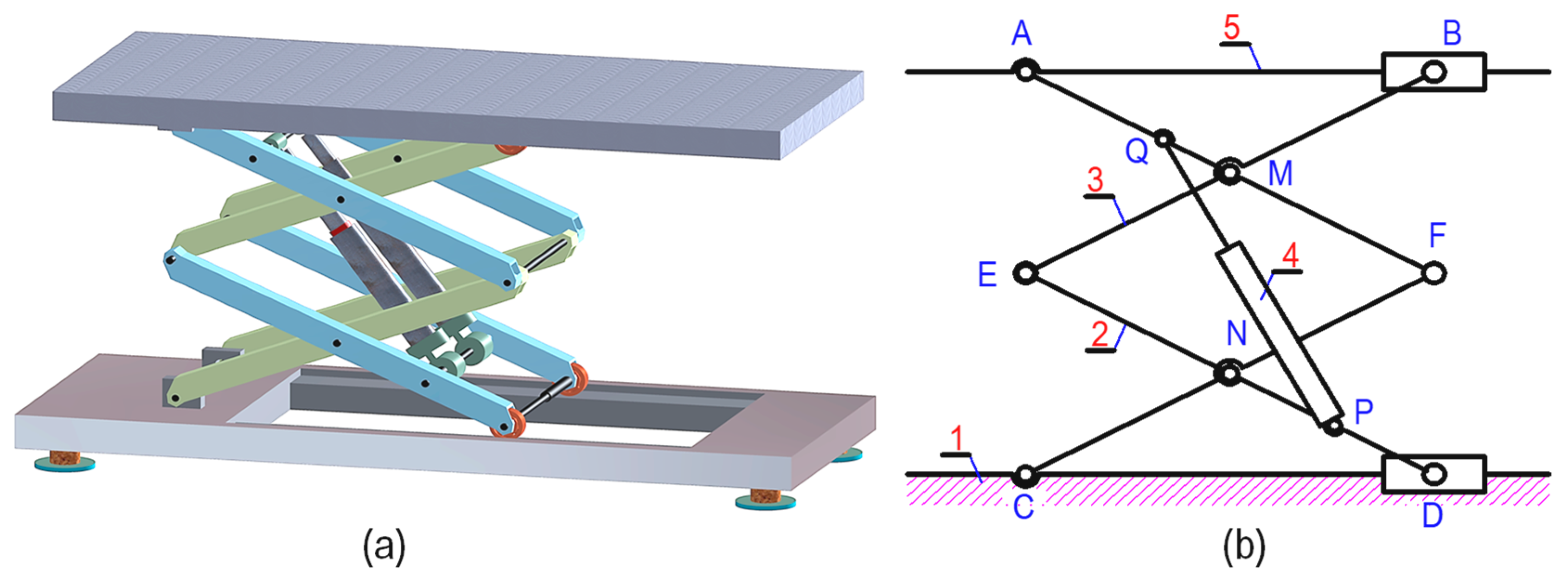
According authors’ knowledge, previous works studied lift table structures with the hydraulic cylinder positioned between adjacent arms. This paper focuses on analyzing a specific structure of the double-stage scissors lift, which arranges two cylinders between parallel arms as shown in Figure 1. Compared to earlier researches, the proposed method consists of merits and novelties as follows:
- The parametric dimension technique is proposed to analyze both the geometry and loads of the double-stage scissors lift as functions that depends on the design parameters. This means that instead of using finite element analysis, the loads on joints and geometries of the system can be determined through functions, which can reduce the time required for model construction and simulation;
- Working Model software is applied to evaluate the accuracy of the proposed method;
- Based on the evaluation of the design parameters, designers simply determine a suitable configuration of the double-stage scissors lift, which meets the working requirements of the system, i.e., optimal lifting height, maximum load, the type of lift object, and stability of the system.
The remained sections are the following. Section 2 presents the mathematical model by using parametric dimension technique for the double-stage scissors lift. In Section 3, the computation of loads for the scissor lift is investigated. The experimental testing by using the Working Model software to verify the accuracy of the proposed method is given out in Section 4. Section 5 describes application examples for the design of the double-stage scissors lift. Finally, conclusions are drawn in Section 6.
2. Mathematical Model for Double-Stage Scissor Lift Analysis
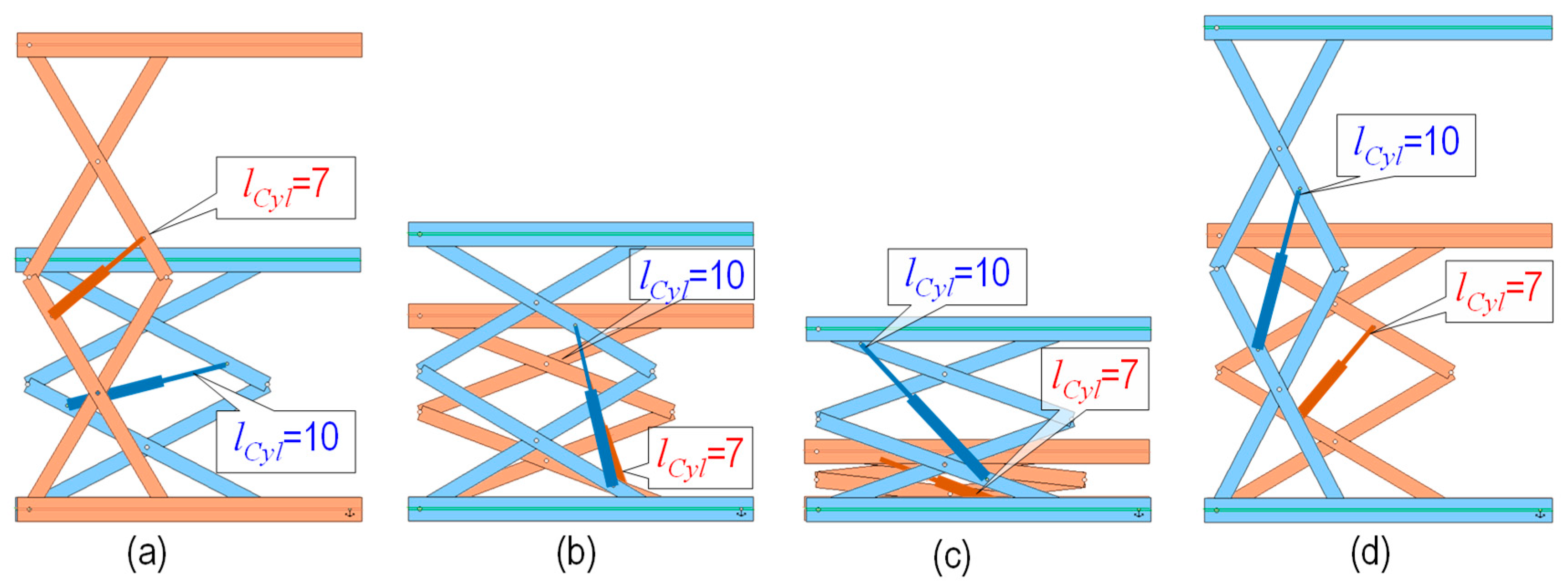
Observing the operation of different types of structures reveals that when the cylinder extends or retracts, the platforms will accordingly move up or down to the corresponding height h. Depending on the orientation of the cylinder (positions of points P and Q on arms), height of the platform will be varied corresponding to the change of cylinder length (PQ, or lCyl). Figure 2 illustrates different orientations of the same cylinder with an arm length of AF = CF = DE = BE = 10 m. It can be observed that although the cylinder only moves in the range of lCyl min = 7 m and lCyl max = 10 m, the displacements of the platforms are different with distinct orientations. Moreover, the change in angles between arms at joints E, F and the distance l between supports A and B also affects the stability of the platform (c.f. Figure 3), which limits the working of the device and the cylinder. Not to mention the load on each joint, which varies during operation, directly depends on the orientation of the cylinders. These small changes also affect the entire system, making it challenging to construct accurate testing models for fabrication.
To investigate the influence of the cylinders’ orientation on the movement of platforms, arrangement dimensions are assigned with design parameters proportionally to the arm’s length. If the length of one arm is denoted by , these design parameters will correspond as
The cylinder length can be set by
in which and (with lCyl max and lCyl min are the longest and shortest length of cylinders).
Through analyzing the structures as shown in Figure 2, the authors found that when changing the position of the mounting joints P and Q of the cylinders on parallel arms, there are two situations related to the operation of the system, including (a) (platform lower when cylinder extends, Figure 2a) and (b) (platform raises when cylinder extends, Figure 2b–d). The calculation process for these cases can be processed with the following steps.
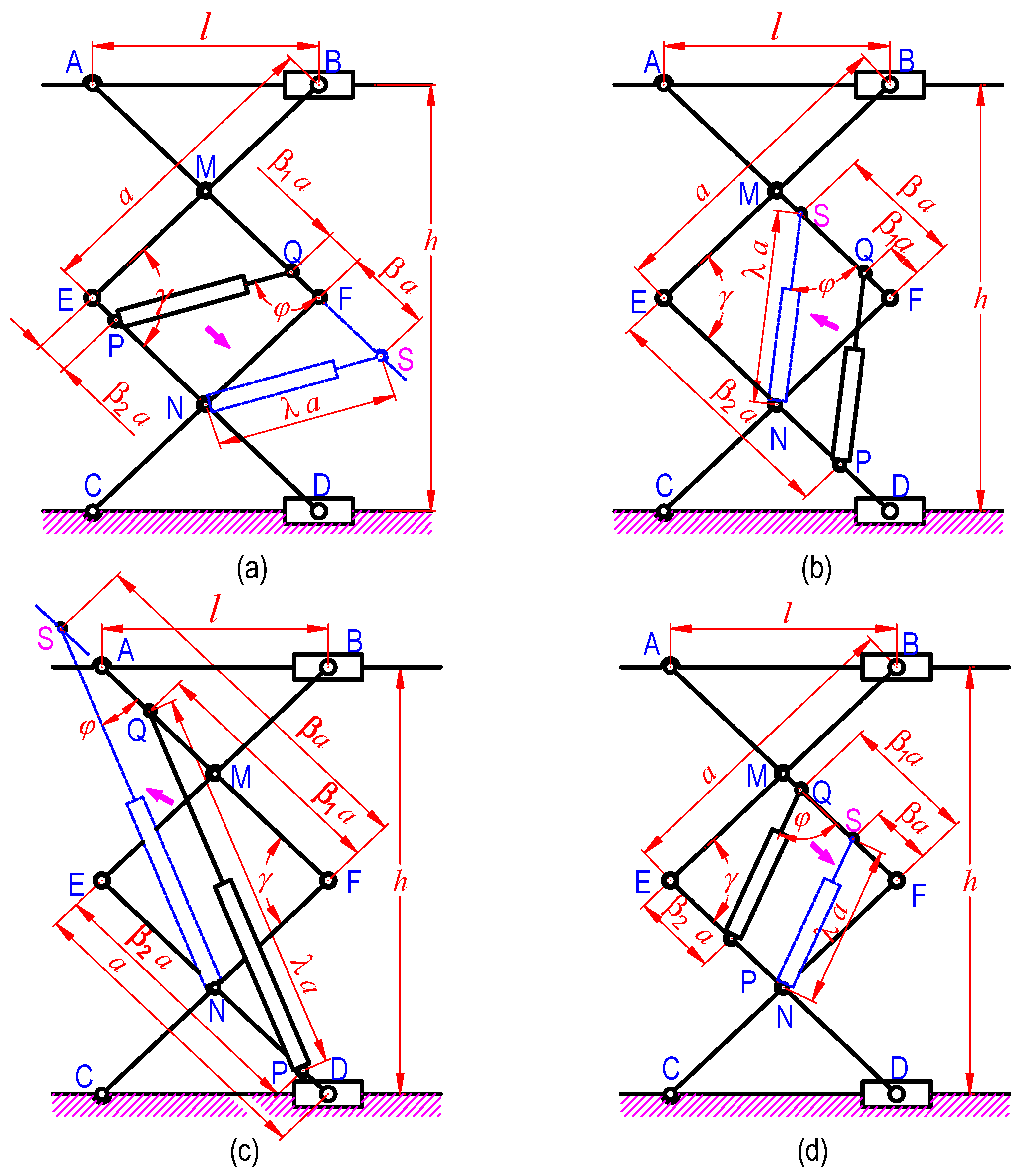
According to the given structure of the system, because the cylinders are arranged in parallel arms AF and ED, they can be relocated so as connecting joint P overlaps with point N without affecting the motion characteristics of the system. Figure 3 describes the resulting structures of four cases from Figure 2 with cylinders PQ parallel moved to NS.
After relocated, the new positions of point Q will be S with
The angle in triangular SFN can be calculated as
Substitute Equation (4) into Equation (5), we get
The platform height, denoted by , can be determined as
When the cylinder extends from lCyl min to lCyl max, the height of the platform correspondingly changes with a distance . This distance is computed by
This distance is also a function depending on parameters, i.e., and . It is assigned as the lifting ratio , which is a significant characteristic of the lifting system. The lifting ratio is calculated by
Along with the movement of the platform, the distance l between supports A and B affects the stability of the system and changes according to the relationship of them. l is calculated from Figure 3 as
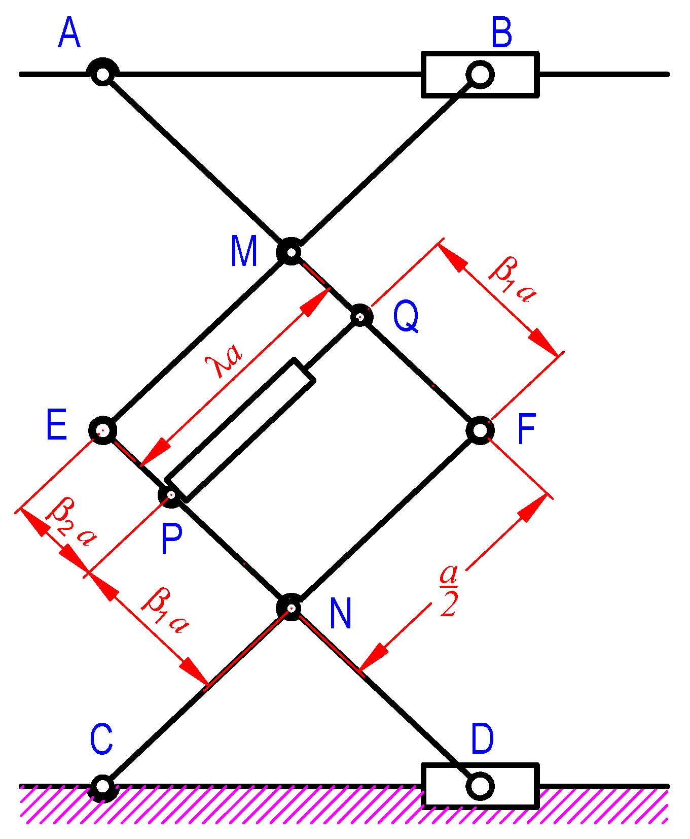
It should be noted that, for the case , the structure becomes as shown in Figure 4. Due to the construction of the device, opposite arms move in parallel direction. For this, NP is always parallel with FQ; therefore, . This is contradictory because PQ is the cylinder of which the length is varied. The operation of cylinders (extending or retracting) in this case will have resulted in damaged arms and even broken the whole devices. For this reason, this configuration must be avoided in design and manufacturing.
3. Computation of Loads
The force analysis is very essential in the scissor lift design because this easily determine the change of loads on every component in different positions of the device, which depends on the operation of the cylinder. This process also assists in selecting bearings at joints and determining the appropriate size for the arms to avoid deformations due to overload or excess strength, which increases the weight and cost of manufacturing.
Since the device is symmetric (two cylinders and eight arms divided into the front and the back mechanisms, c.f. Figure 1), determining reactions at each joint and the thrush force of cylinders is investigated for one side of the structure. The lift weight of the objects/people is called P, and the weight of the platform is denoted by Wp. The total load, denoted as PG, is determined by
where point G is the centroid of total load.
To be more specific for the calculation process, some parameters are added, including the load of the arms W, the distance lG between G and fixed support A (lG can be negative if G is on the left of point A, and lG > l if the platform is raised too high that support B moves to the left side of G, see Figure 5). Assuming the platform is raised slowly so that the effect of inertia forces in the system can be neglected, and considering no resistance in the joints’ motion, which disregards the influence of friction, the calculation procedure can be carried out with static analysis.
Releasing connections at supports A, B, C and D, the reactions at these joints can be determined by moment equilibrium equations as follows:
Replacing the cylinder with thrust force FCyl and releasing the connection at joints, i.e., M, N, E, and F into directional component reactions in the x- and y-axis, the free-body diagram in each arm of the mechanism is presented in Figure 6.
Equilibrium equations for moment and forces are applied for each arm (see Figure 6).
For arm BE
For arm CF
For arm AF
For arm DE
Combining Equations (17), (19), (21) and (23), we get
Drawing the relation between RMx and RNx from Equations (18) and (20) is
Substituting Equations (10), (12)–(14) into Equation (24), the thrush force of the cylinder is computed as
From Figure 3, the relation between and can be determined as
Thus,
For is the angle between vectors and , this angle can be derived from relation in triangular SNF (see Figure 3)
Equation (29) can be expressed as
Substituting Equations (6), (28) and (30) into Equation (26), we get
In Equation (31), the negative sign (-) with presents the retracting of cylinders to raise the platform (see Figure 2a).
It can be observed that in Equation (31) the coefficient lG is omitted; thus, the thrust force of cylinders does not depend on the position of the total load PG. However, since this parameter is still presented in the reaction at other joints, especially at the main supports (A, B, C and D), the change of distance lG affects to the load on each arm and directly affects to the stability of the lift.
The reactions at revolution joints M, N, E and F can be conducted as following steps:
Combining Equations (17) and (21), we get
Substituting Equations (6), (12), (13), (16) and (31) into Equation (32), REx is
Combining Equations (19) and (23), we have
Substituting Equations (6), (14), (15), (18) and (31) into Equation (34), RFx is
Drawing RMy from Equation (17)
Substituting Equations (6), (10), (12) and (35) into Equation (36), we get
Likewise, RNy is calculated from Equation (19)
Substituting Equations (6), (10), (15) and (35) into Equation (38)
Substituting Equations (6), (10), (12) and (33) into Equation (40), we get
Likewise, substituting Equations (6), (10), (15) and (35) into Equation (42), we get
The reactions in component joints then can be obtained from directional components as follows:
4. Numerical Simulation of the Model
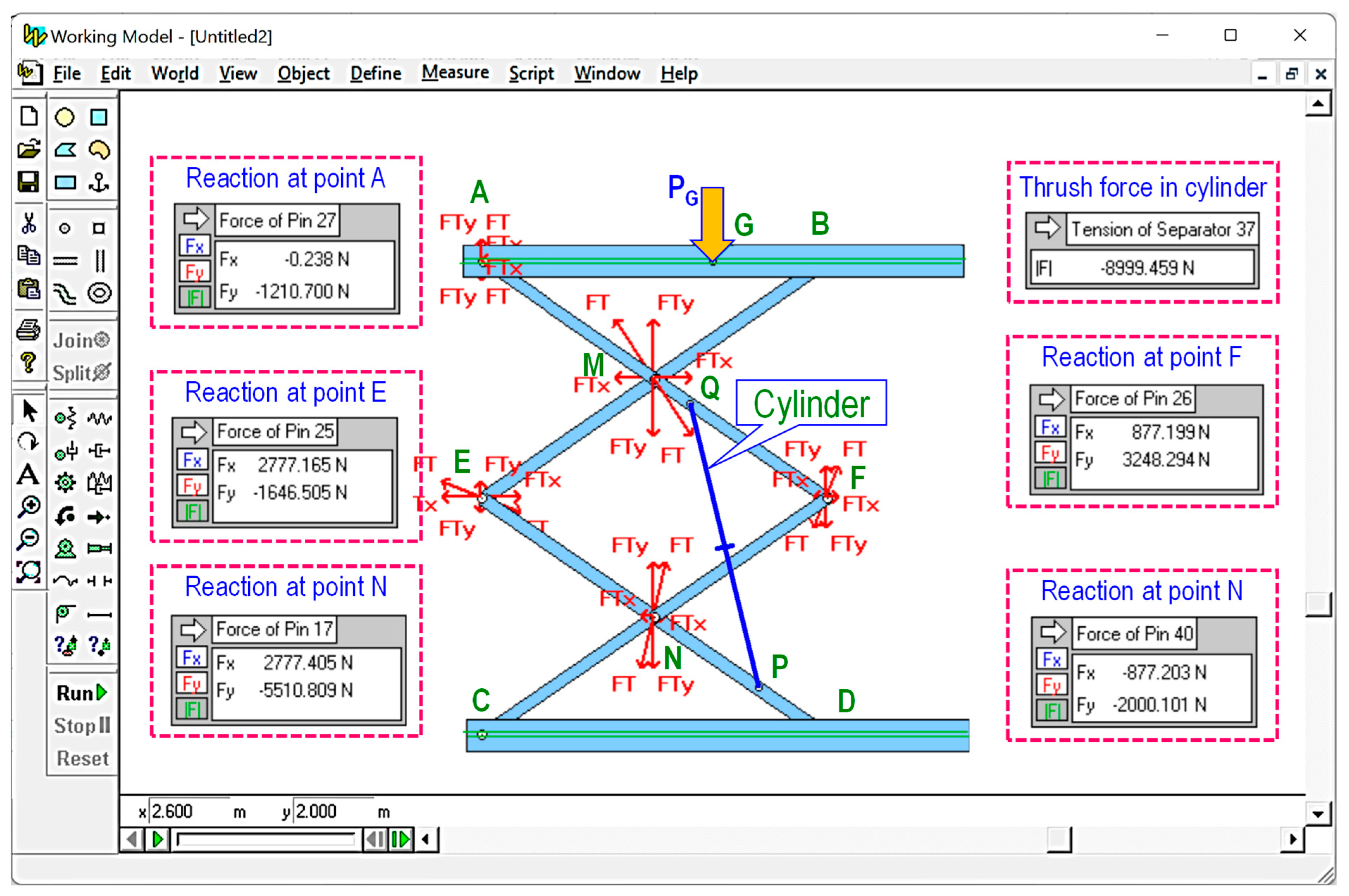
To verify the accuracy of the calculation method, 2D physical models were constructed in Working Model software for comparing reactions at joints. The cylinder was replaced with a separator element whose length can be adjusted to verify the platform’s height. By assigning external force PG = 5000 N and arms’ weight W = 75 N (corresponding to features from industrial devices, solid steel bars of 20 × 40 mm), loading on every joint and thrush force of the cylinder can be acquired from the physical model using the “Measure” option as presented in Figure 7. By changing the orientation of cylinders and cylinder’s length in the model, the reactions are measured and stored for comparing with those obtained by the proposed method, as summarized in Table 1.
The difference of reaction between the parametric method and the simulation model can be expressed as
in which F1 is reaction measured from Working Model; F2 is reaction obtained by the calculation in Equations (31), (33), (35), (37), (39), (41) and (43).
The first two models in Table 1 describe measurements from the same structure with the cylinder’s length of 0.59 and 0.45 m, respectively. The remaining configurations in Table 1 present the configurations of the system with some random orientations of cylinders. As seen that the differences are less than 0.3%. The results prove the accuracy of the proposed calculation method in determining the reaction within the mechanism. These errors also indicate the existence of some environmental factors that affect the modeling result (friction, physical contact in joints, or even dynamic forces between parts). The deviation errors Δ also show that we can directly determine loads in the structure without constructing the system in virtual models, which take a long time to create, as well as simulate.
5. Application Examples
This section presents the application examples in the design of double-stage scissor lifts for two cases: (1) design with the best lifting height and maximum load, (2) design with choosing the appropriate cylinder.
5.1. Designing Double-Stage Scissor Lifts with Optimal Lifting Height and Maximum Load
Designers can determine the suitable configuration for the system, which is selecting the orientation of cylinders with given parameters (minimum length, total strokes, and maximum thrust force) to obtain the optimal lifting height and maximum load properties. They can also accurately choose the cylinders from the market to meet the operation required for the system.
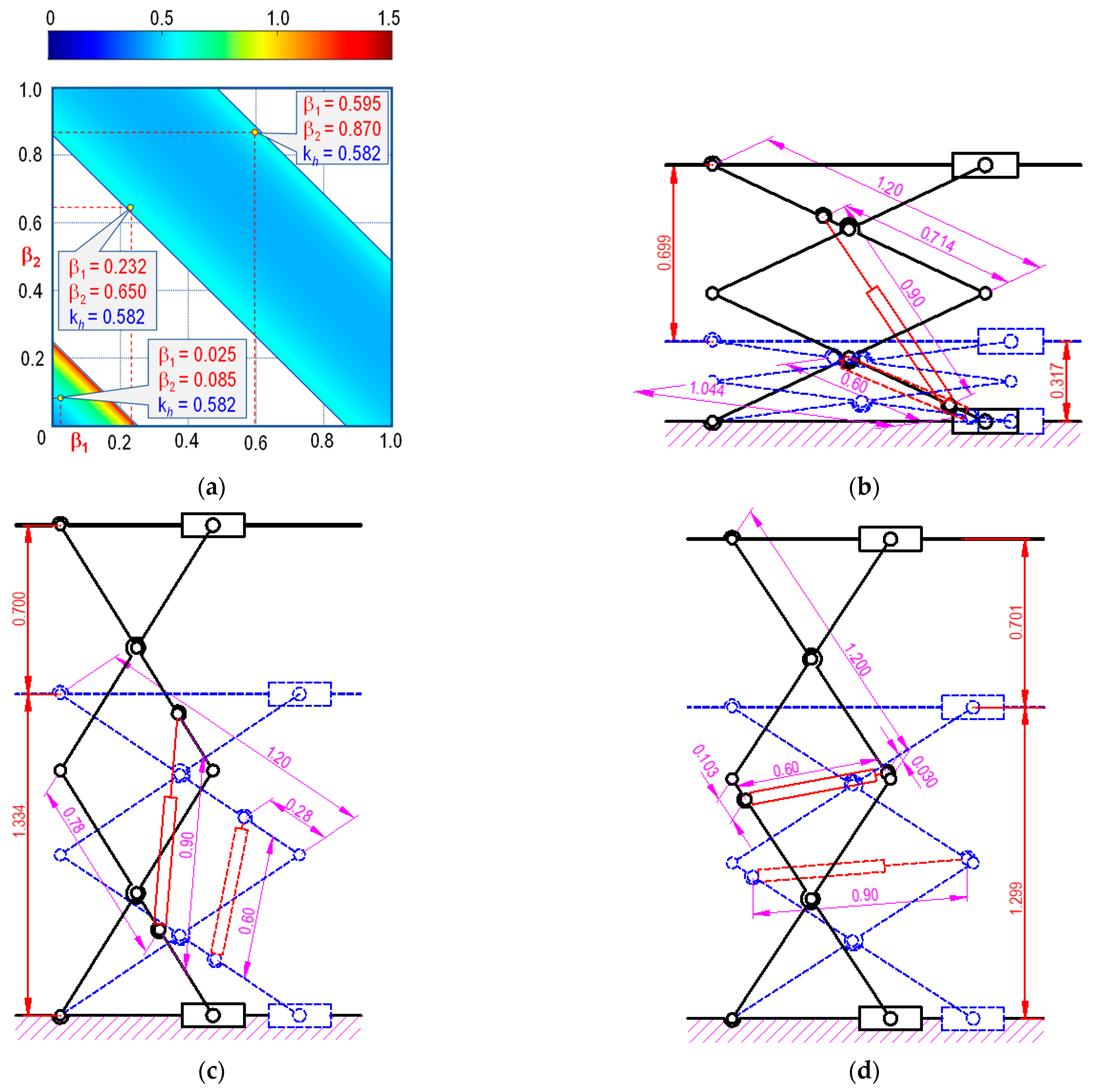
For example, from a given double-stage structure with rigid arm length a = 1.2 m and two cylinders whose parameters are known (lCyl min = 60 cm; Stroke s = 30 cm and maximum thrust force FCyl = 10 kN), the lifting ratio kH for different orientations of the cylinder can be calculated, using Equation (6). To improve the structure stability, initial constraints like the range of angular arm ( and ), and the working conditions of the device were added for the calculation. Figure 8 presents the varying of kh according to and , corresponding to the operating range of cylinders.
For detail analysis, three structures with the same kh value representing different cylinder orientation cases (, and ) were compared. The limiting positions of these cases, illustrated in Figure 8b–d, indicate that although having the same platform displacement, the lowest position from the first case is the most compact, while the initial heights in other configurations are nearly the same (1.334 and 1.299 m).
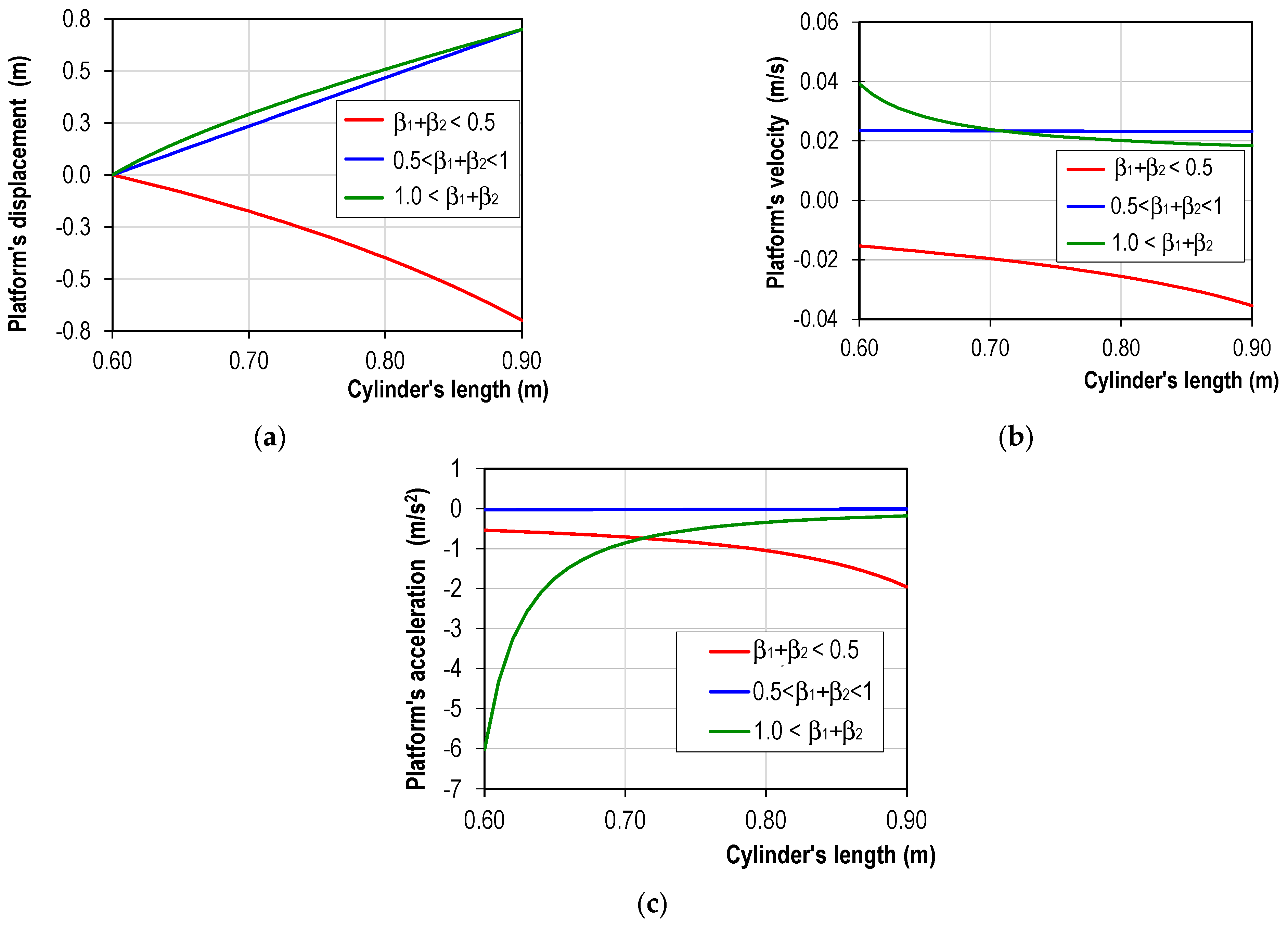
In evaluating the raising rate of the device, since the elevation of platform h can be calculated by the function of , , and , the raising velocity of this component can be derivated from the displacement graph of the cylinders. By taking the derivative of the cylinder displacement in Equation (7), the velocity of the platform corresponding to the cylinder displacements can be expressed using the following equations:
In which is the displacement rate of cylinder and is the retract/extend speed of the cylinder.
We can also calculate the acceleration of the platform by deriving the velocity as follows:
We assume cylinders from the three cases are operated with the same rate of 0.008; this means that cylinders are extended/retracted with constant velocity . Substituting the velocity of cylinders to Equations (49) and (50), the detail movements of the platforms corresponding to displacements of cylinders in the three mentioned cases from Figure 8 are presented in Figure 9.
It can be seen that while the platforms in models 1 and 3 have curved displacements, resulting in variable velocity and acceleration oscillating within the range of 0.02 m/s and up to 0.006 m/s2. Otherwise, the movement of model 2 exhibits linear motion, with a small velocity oscillation of 4 × 10⁻⁴ m/s, and the acceleration is approximate to zero, i.e., 2 × 10⁻⁵ m/s2. These graphs also demonstrate that for the same requirement of vertical displacement of the platform, the second design provides higher stability (with virtually no presence of inertial acceleration).
Based on these characteristics, different applications can be proposed to exploit each type of the device. For example, the third model is recommended for raising sand molds in the casting foundry to avoid impacts during movement. The second model is beneficial for environments that require zero vibration and accurate movement of objects with a constant velocity. On the other hand, since the first configuration still retains the advantage of high lifting capability and compactness, the cylinder must be equipped with a precise pumping controller to ensure slow operation and prevent impacts between parts due to the high speed and acceleration of the platform.
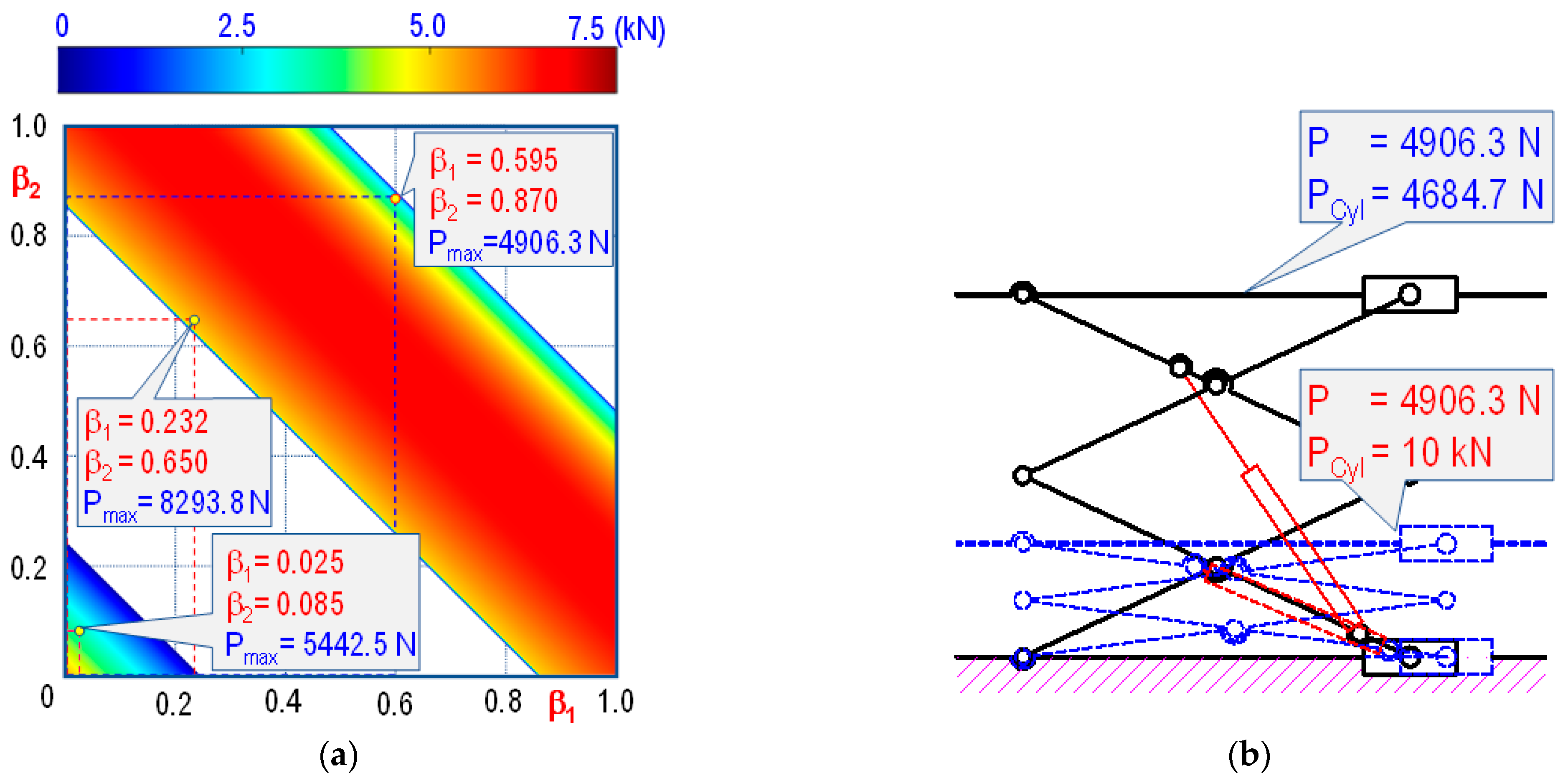
From the equation of cylinder thrush force, we can determine the maximum load for different layouts. Assuming the weight of each arm in the device W = 30 N (stainless steel hollow bar, 20 × 40 mm), and of the platform Wp = 80 N, the lifting load P on the device can be calculated from the thrust force of the cylinder, drawn from Equations (7) and (25)
Since the requirement of thrush force reduces when lifting an object from the lowest to the highest positions, the maximum load Pmax is calculated based on hmin, or minimum length of cylinders () for and maximum lengths () for . Figure 10 presents the varying maximum load according to the different orientations of and by using the given cylinders. Three configurations in Figure 8 were chosen to verify the calculation result, as shown in Figure 10. To further investigate the effect of these loads on the operation of the cylinder, the highest and lowest positions of the structures are included in the analysis (see Figure 10b–d).
The detailed results comparing three configurations in the Figure 10 shows that the maximum load of the second configuration can raise much larger than the others (approximately 80% of the capability of cylinders). On the other hand, although the first structure is the most compact than others, its allowable load is only 45% of the capability of cylinders.
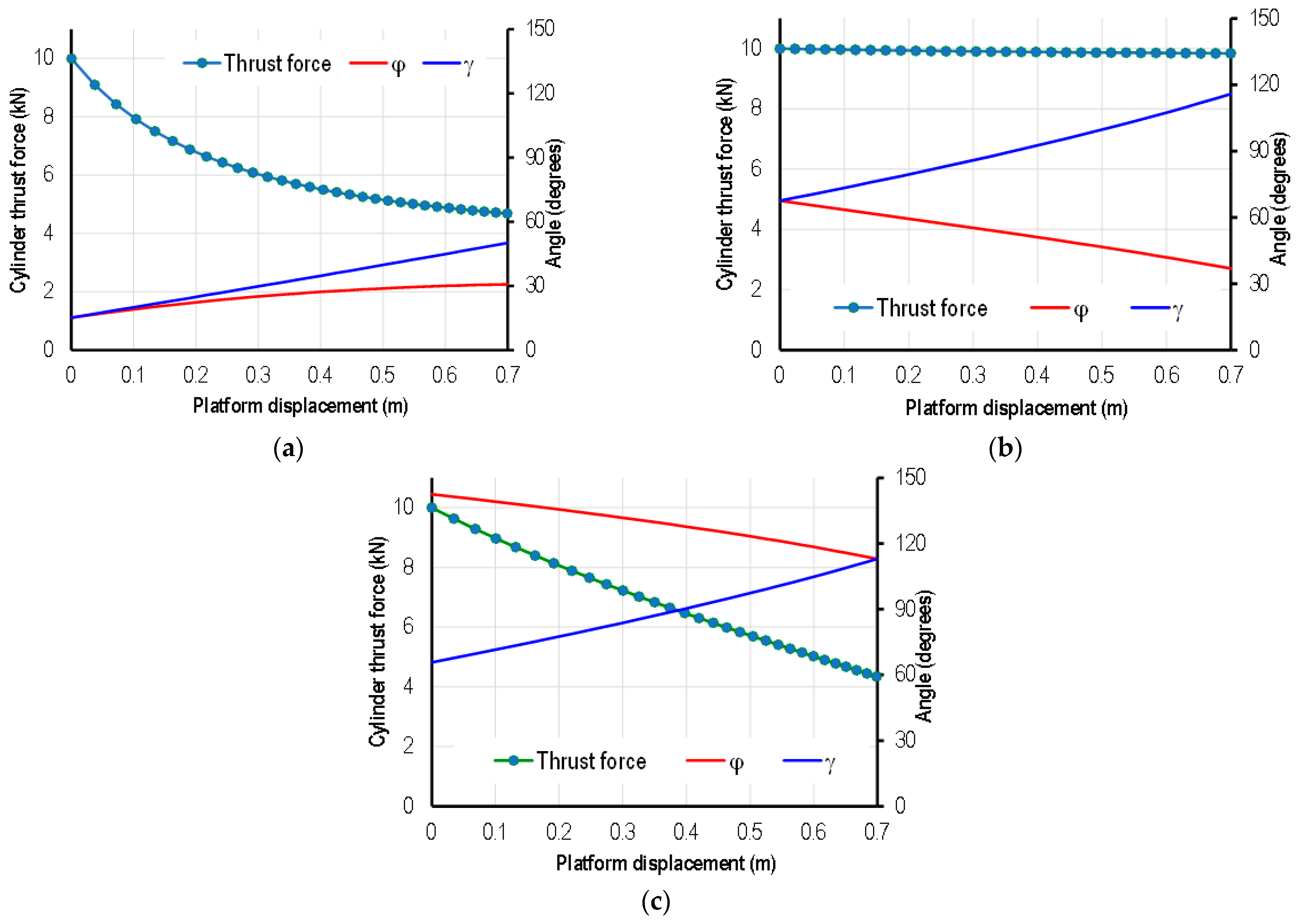
The results from Figure 10 also indicate that even though the initial load is constant, the required thrust force for raising the platform to higher positions of the cylinder is significantly reduced (up to 57% in the first configuration and 52% in the third, but about 0.2% in the second configuration). A possible explanation for this feature is that when the platform is raised, the angle γ between arms, and the angle φ between cylinder and arm varies, which changes reactions from axial directions into tangential directions and increases the impact of the thrust force on the bending moment of arms. Not to mention that although three structures share the same platform’s displacement (0.7 m), the difference of γ also influences the magnitude of the reaction in cylinders. Figure 11 presents the change of minimum thrust force corresponding to the maximum load and angles γ and φ in each configuration.
5.2. Designing Double-Stage Scissor Lifts for Selecting the Appropriate Cylinder
Another application of the parametric method is to select the appropriate cylinder in case the position of the cylinder is given. For example, if the dimensions for the cylinders’ arrangement are , and maximum load is FCyl= 10.0 kN, the structure of cylinder (length, stroke and force) can be calculated and summarized as presented in Figure 12.
According to the structure stability’s requirement, since the angular γ between arms should be adjusted between 10° and 120°, the operation length of the cylinder must be ranged from 0.50 to 1.46 m.
From the diagram in Figure 12, if the platform is required to be raised 0.5 m, we can either select cylinders with a 0.67-m initial length and 0.26-m stroke (corresponding to hmin = 0.7 and hmax = 1.2 m) with a maximum load of 10.8 kN or select other ones with a 1.10-m initial length and 0.30-m stroke (hmin = 1.5 and hmax = 2.0 m) with a maximum loading of 8.4 kN (has longer stroke but require smaller thrust force).
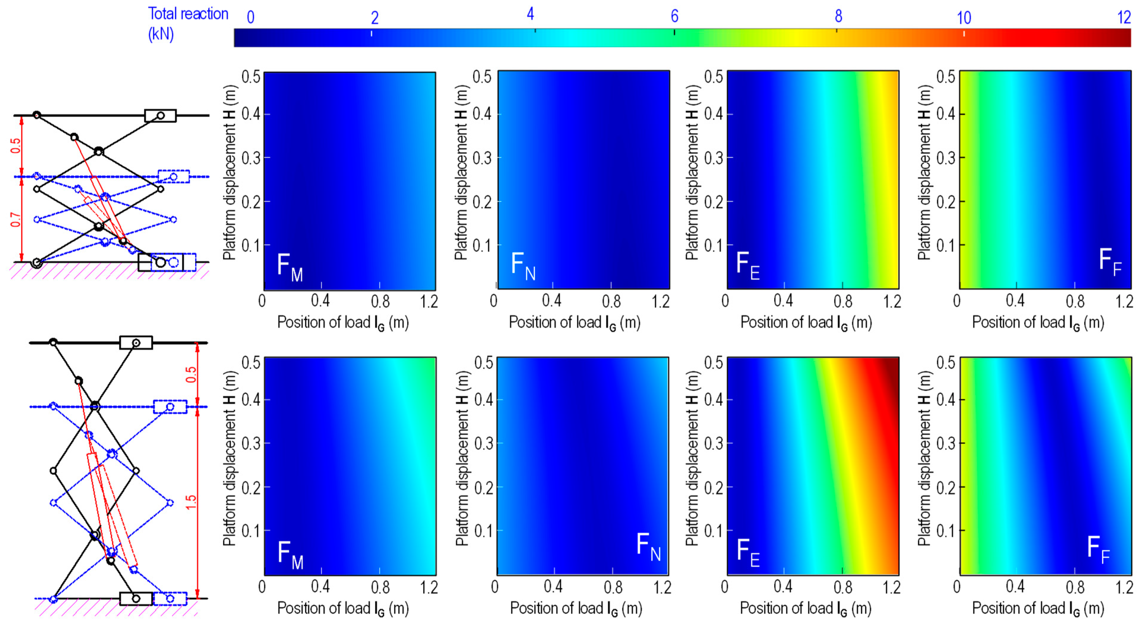
In addition, for selecting the appropriate cylinders, the acquired expressions also allow the determination of limited load for designing connecting joints. For more detailed analysis, the two types of selected cylinders are used to inspect the change in reaction at other revolution joints, i.e., M, N, E, and F. Assuming the platform width is 1.2 m (equal to the length of one arm) to allow lifting object moving along the platform (0 < lG < 1.2) during the operation of the system, Figure 13 presents the change of reaction at joints for the selected scissor lifts. It can be observed that while the first configuration requires higher cylinder thrust force, reaction at joints in this case is much smaller (only 4.7 kN, comparing with the maximum reaction in the second configuration, i.e., 13 kN). Moreover, since the first configuration has lower initial height, the change of distance l between support A and B and platform’s height is also smaller than the second one, which makes more stable for this structure.
6. Conclusions
This study proposes applying the parametric dimension technique in designing double-stage scissor lifts with the cylinders arrange on parallel arms. The mathematic model of the configuration and load computation of the scissor lifts are proposed. The results of the proposed method bring the great significance in designing scissor. In addition, using this method can recommend designers to choose the optimal configuration for each lifting object. From the obtained results, conclusions are drawn as follows:
- -
- By assigning dimensional parameters for the arrangement of cylinders, the information of the system (platform’s height, stability of platforms, and reaction on joints) can be accurately calculated. This allows the selection of components without the need to construct 3D models for complicate inspections or experiments;
- -
- From design requirements, the appropriate information of the lift system can be efficiently and robustly constructed. Designers can select the cylinder to assembly in the given position, or choose the orientation for cylinders that satisfy the operation of platform;
- -
- From the obtained reactions and information of the designed lift, the detailed structure of the system can be optimized, which reduces the manufacturing cost and even calculation time;
- -
- The accuracy of the proposed method is verified by using the Working Model software.
Author Contributions
A.-T.D.: Conceptualization, methodology, investigation, resources, software, writing-original draft. T.T.N.N.: Conceptualization, methodology, investigation, resources, writing-original draft, writing-review and editing, supervision. All authors have read and agreed to the published version of the manuscript.
Funding
This research received no external funding.
Data Availability Statement
Not applicable.
Acknowledgments
The author would like to thank Thai Nguyen University of Technology, Vietnam for supporting this research.
Conflicts of Interest
The authors declare no conflict of interest.
Nomenclature
| a | Length of one scissor’s arm |
| Design parameters | |
| Cylinder’s length | |
| Coefficient of cylinder’s length | |
| Angle between adjacent arms of the double-stage lift | |
| Angle between cylinder and the scissor arm | |
| h | Elevation of the platform |
| Velocity of the platform | |
| Acceleration of the platform | |
| Δh | Height of the platform |
| Lifting ratio | |
| l | Distance between supports A and B on the platform |
| lG | Position of total load PG on the platform |
| Velocity of the cylinder | |
| P | Lift weight of the objects/people |
| Wp | Weight of the platform |
| W | Weight of an scissor arm |
References
- Pan, C.S.; Chiou, S.S.; Kau, T.Y.; Wimer, B.M.; Ning, X.; Keane, P. Evaluation of postural sway and impact forces during ingress and egress of scissor lifts at elevations. Appl. Ergon. 2017, 65, 152–162. [Google Scholar] [CrossRef] [PubMed]
- Paramasivam, V.; Tilahun, S.; Kerebih Jembere, A.; Selvaraj, S.K. Analytical investigation of hydraulic scissor lift for modular industrial plants in Ethiopia. Mater. Today Proc. 2021, 46, 7596–7601. [Google Scholar] [CrossRef]
- Solmazyiğit, İ.; Başkurt, R.C.; Ovalı, İ.; Tan, E. Design and Prototype Production of Scissor Lift Platform 25 Tons Capacity. Eur. J. Res. Dev. 2022, 2, 326–337. [Google Scholar] [CrossRef]
- Soma Raghavendra, C.; Raghunath Reddy, B.; Tech Student, M. Design and Analysis of an Aerial Scissor Lift. Int. J. Eng. Sci. Comput. 2017, 7, 13890–13903. [Google Scholar]
- Hongyu, T.; Ziyi, Z. Design and Simulation Based on Pro/E for a Hydraulic Lift Platform in Scissors Type. Procedia Eng. 2011, 16, 772–781. [Google Scholar] [CrossRef] [Green Version]
- Arunkumar, G.; Kartheeshwaran, R.; Siva, J. Investigation on design, analysis and topological optimization of hydraulic scissor lift. J. Phys. 2021, 2054, 012081. [Google Scholar] [CrossRef]
- Choe, H.; Kwon, Y.; Jo, J.; Ri, K.; Jang, H.; Xing, T. A method to Improve the Stability of Scissor Lifting Platform by using Finite Element Analysis. Int. J. Sci. Res. Sci. Eng. Technol. 2022, 9, 314–322. [Google Scholar]
- Karagülle, H.; Akdağ, M.; Bülbül, İ. Design Automation of a Two Scissors Lift. Eur. J. Res. Dev. 2022, 2, 178–191. [Google Scholar] [CrossRef]
- Spackman, H.M. Mathematical Analysis of Scissor Lifts; Naval Ocean Systems Center: San Diego, CA, USA, 1989. [Google Scholar]
- Kirsanov, M.N. Parallelogram mechanism with any number of sections. Russ. Eng. Res. 2018, 38, 268–271. [Google Scholar] [CrossRef]
- Dong, R.G.; Pan, C.S.; Hartsell, J.J.; Welcome, D.E.; Lutz, T.; Brumfield, A.; Harris, J.R.; Wu, J.Z.; Wimer, B.; Mucino, V.; et al. An investigation on the dynamic stability of scissor lift. Open J. Saf. Sci. Technol. 2012, 2, 8–15. [Google Scholar] [CrossRef] [Green Version]
- Dang, A.T.; Nguyen, D.N.; Nguyen, D.H. A Study of Scissor Lifts Using Parameter Design. In Proceedings of the International Conference on Engineering Research and Applications, ICERA 2020, Thai Nguyen, Vietnam, 1–2 December 2020; pp. 75–85. [Google Scholar]
- Saxena, A. Deriving a Generalized, Actuator Position-Independent Expression for the Force Output of a Scissor Lift. arXiv 2016, arXiv:1611.10182. [Google Scholar]
- Ciupan, C.; Ciupan, E.; Pop, E. Algorithm for Designing a Hydraulic Scissor Lifting Platform. In MATEC Web of Conferences; EDP Sciences: Ulis, France, 2019; Volume 299. [Google Scholar]
- Stawinski, L.; Zaczynski, J.; Morawiec, A.; Skowronska, J.; Kosucki, A. Energy Consumption Structure and Its Improvement of Low-Lifting Capacity Scissor Lift. Energies 2021, 14, 1366. [Google Scholar] [CrossRef]
- Stawinski, L.; Kosucki, A.; Morawiec, A.; Sikora, M. A new approach for control the velocity of the hydrostatic system for scissor lift with fixed displacement pump. Arch. Civ. Mech. Eng. 2019, 19, 1104–1115. [Google Scholar] [CrossRef]
Figure 1.
Structure of the system: (a) the 3D model and (b) 2D model of the mechanism 1. Ground, 2. Cylinder-connected arm, 3. Cylinder-free arm, 4. Cylinder, 5. Platform.
Figure 1.
Structure of the system: (a) the 3D model and (b) 2D model of the mechanism 1. Ground, 2. Cylinder-connected arm, 3. Cylinder-free arm, 4. Cylinder, 5. Platform.

Figure 2.
Illustrate the influences of cylinder arrangement on the operability of the platform. (a) Model 1; (b) Model 2; (c) Model 3; (d) Model 4.
Figure 2.
Illustrate the influences of cylinder arrangement on the operability of the platform. (a) Model 1; (b) Model 2; (c) Model 3; (d) Model 4.

Figure 3.
Relocating cylinders from Figure 2 to new positions. (a) Model 1; (b) Model 2; (c) Model 3; (d) Model 4.
Figure 3.
Relocating cylinders from Figure 2 to new positions. (a) Model 1; (b) Model 2; (c) Model 3; (d) Model 4.

Figure 4.
Schematic diagram of the system for the case .

Figure 5.
Releasing connections on the ground (CD) and platform (AB).
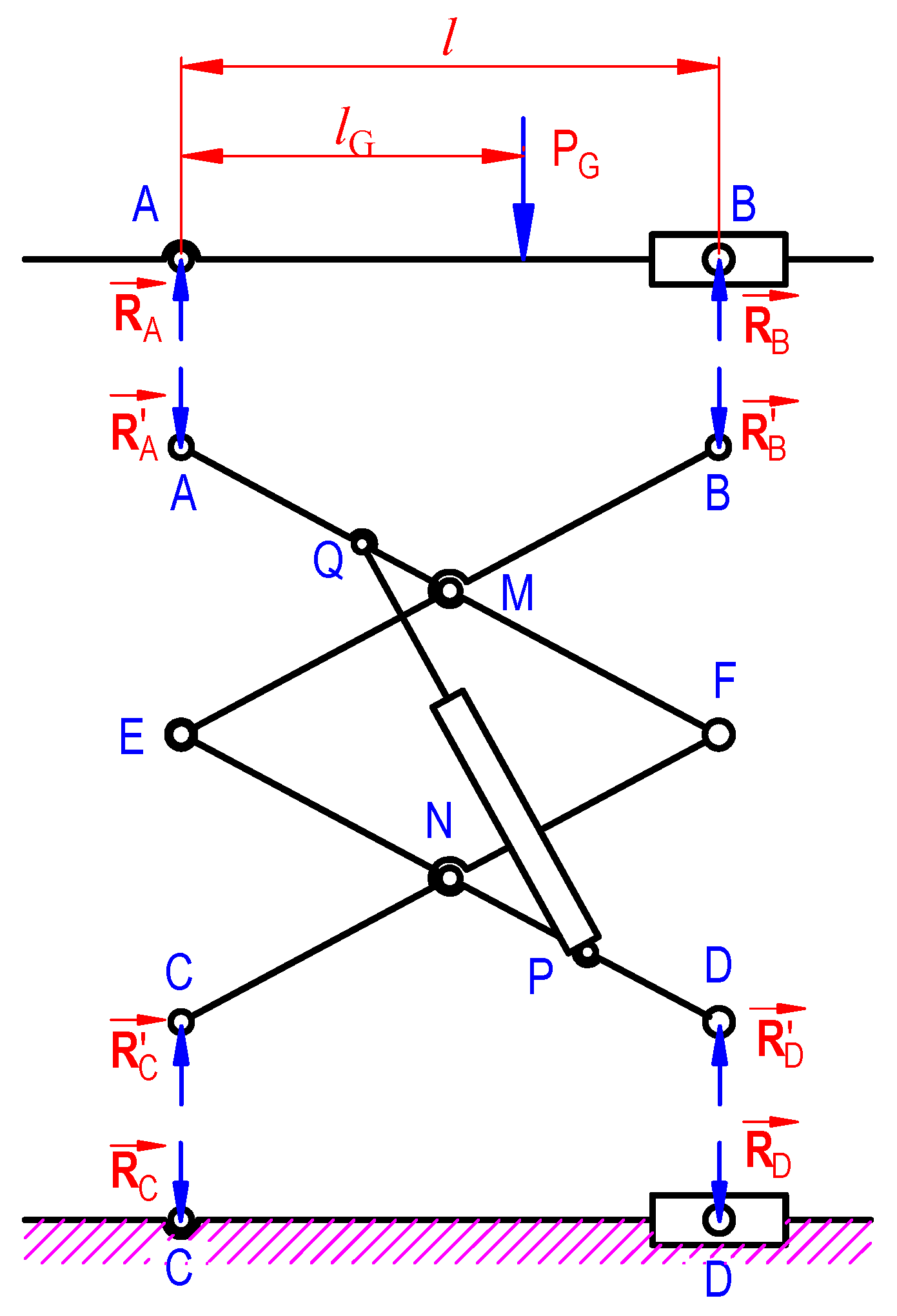
Figure 6.
Releasing connecting joints in the component arms.
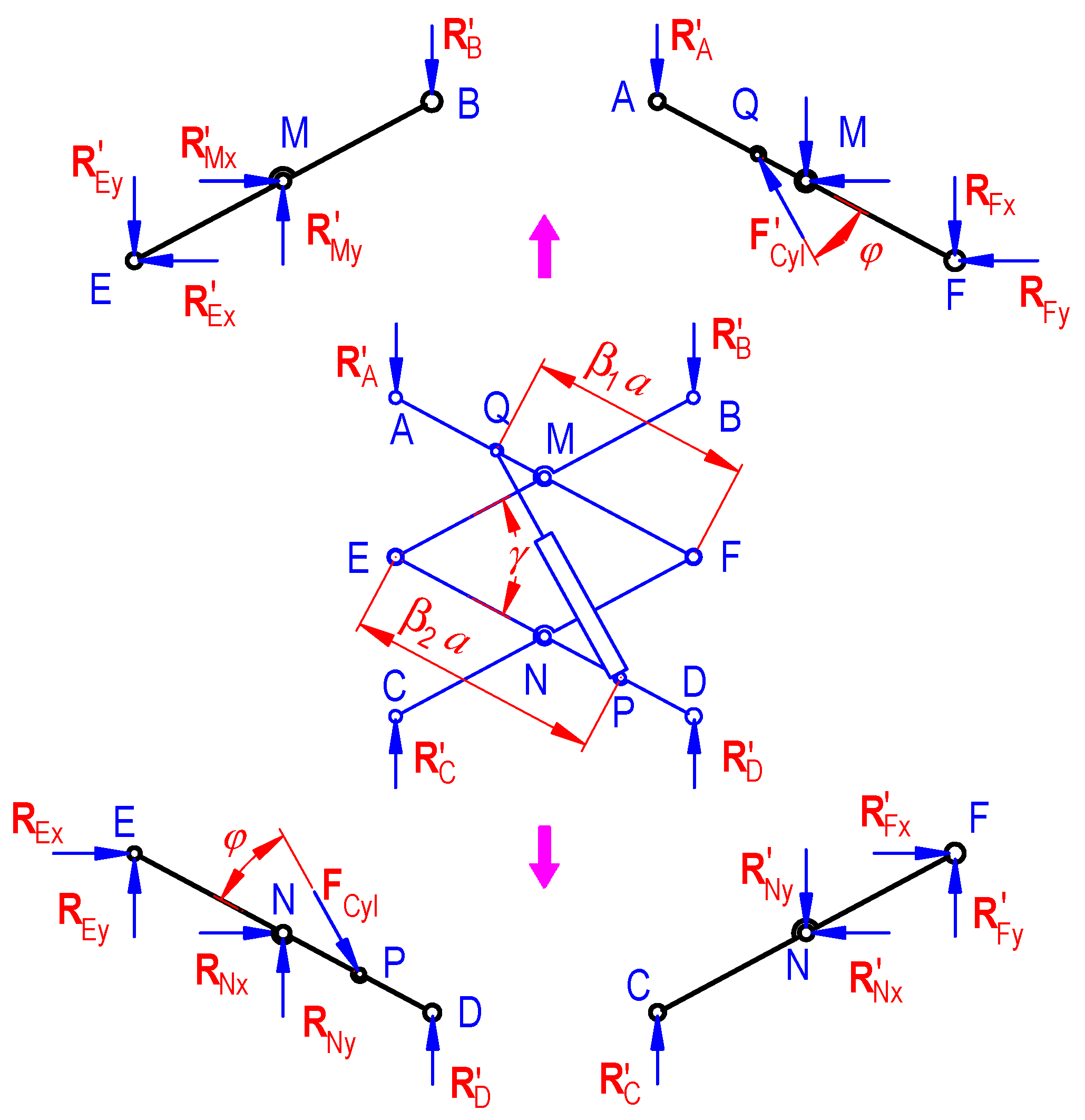
Figure 7.
Extract reactions at joints using Working Model (a = 1 m, β1 = 0.4, β2 = 0.8, λ = 0.75, W = 75 N, PG = 5000 N, lG = 0.6).
Figure 7.
Extract reactions at joints using Working Model (a = 1 m, β1 = 0.4, β2 = 0.8, λ = 0.75, W = 75 N, PG = 5000 N, lG = 0.6).

Figure 8.
Configurations of the scissor lifts from the given data set (lCyl max, lCyl min): (a) lifting ratio kh; and three configurations using the graph data representing (b) , (c) , and (d) (Unit: m).
Figure 8.
Configurations of the scissor lifts from the given data set (lCyl max, lCyl min): (a) lifting ratio kh; and three configurations using the graph data representing (b) , (c) , and (d) (Unit: m).

Figure 9.
Kinematic of the platform in three cases from Figure 8 during the operation of the cylinder: (a) displacement, (b) velocity, and (c) acceleration.
Figure 9.
Kinematic of the platform in three cases from Figure 8 during the operation of the cylinder: (a) displacement, (b) velocity, and (c) acceleration.

Figure 10.
(a) Determination of maximum load Pmax on the platform; (b–d) the change of cylinder thrush force in three selected cases for W = 30 N and Wp = 80 N.
Figure 10.
(a) Determination of maximum load Pmax on the platform; (b–d) the change of cylinder thrush force in three selected cases for W = 30 N and Wp = 80 N.

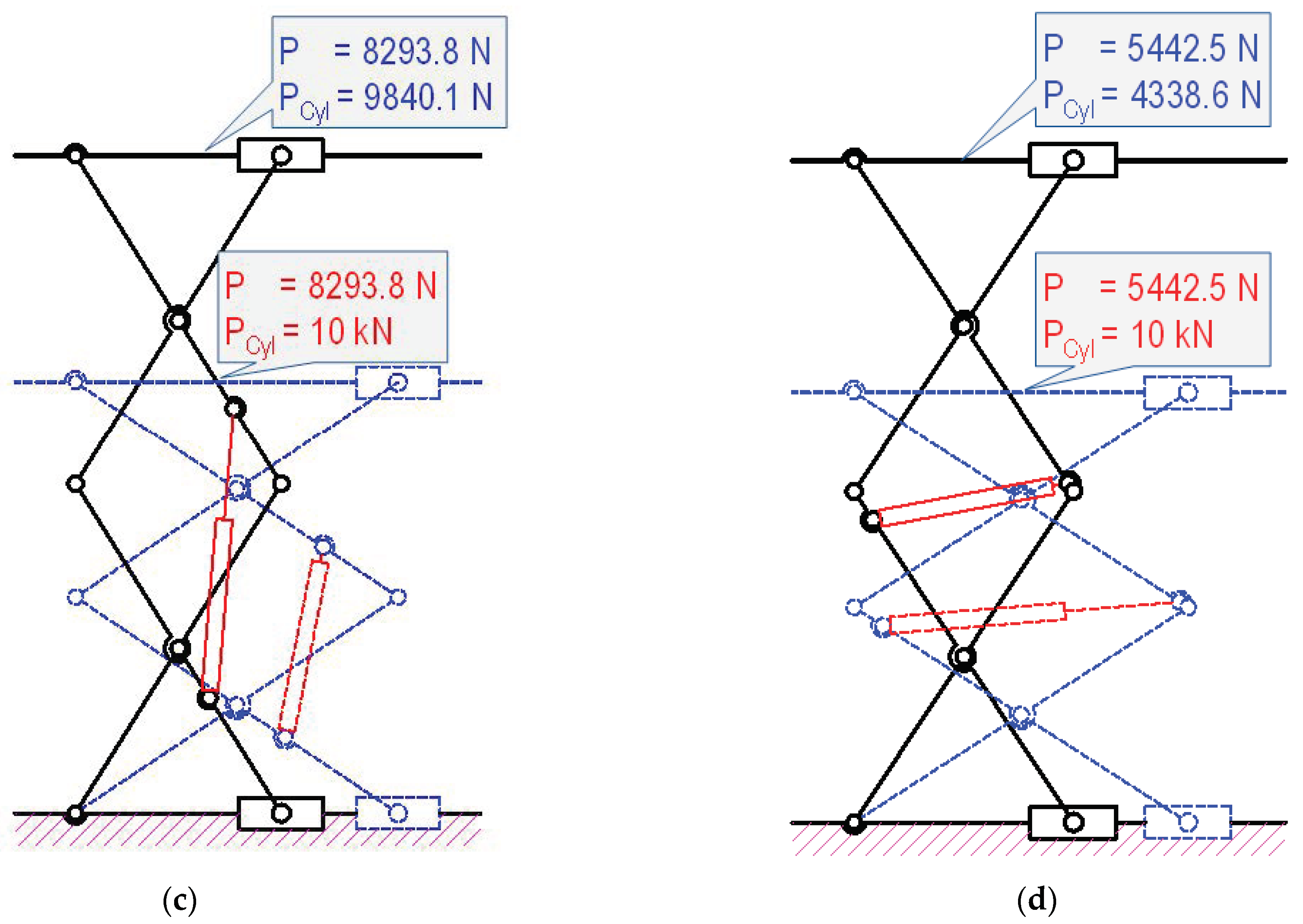
Figure 11.
The change of thrust force and angular between arms in different configuration: (a) model 1, (b) model 2, and (c) model 3.
Figure 11.
The change of thrust force and angular between arms in different configuration: (a) model 1, (b) model 2, and (c) model 3.

Figure 12.
Selecting cylinder corresponding to the raising height and loading requirement (a = 1.2 m; ; P = 10 kN, W = 30 N).
Figure 12.
Selecting cylinder corresponding to the raising height and loading requirement (a = 1.2 m; ; P = 10 kN, W = 30 N).
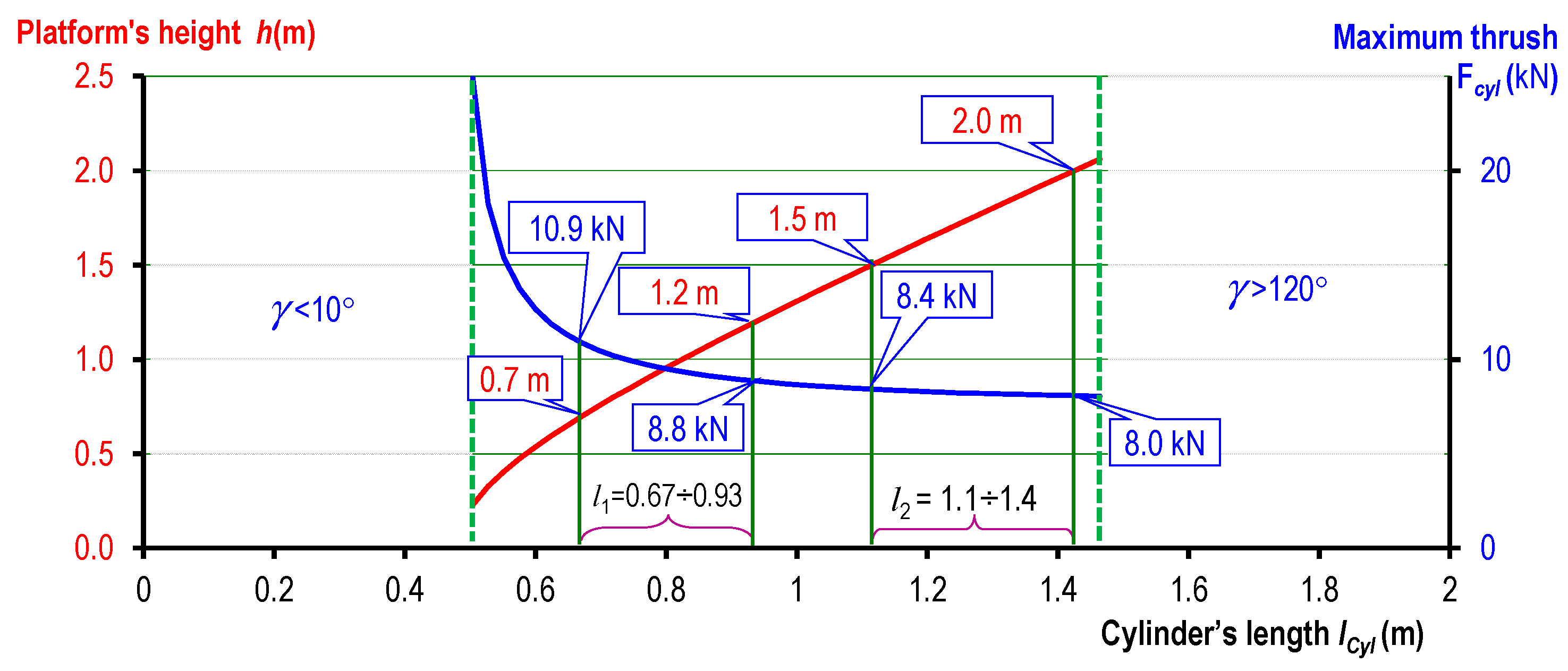
Figure 13.
The change of reactions at joints during the operation of the selected systems.


Table 1.
Comparing reactions between the calculation method and the simulation model.
| a = 1 m; W = 75 N PG = 5000 N | lG = 0.1 m | lG = 0.5 m | |||||
|---|---|---|---|---|---|---|---|
| F1 (N) | F2 (N) | F1 (N) | F2 (N) | ||||
| FCyl | 124,566.36 | 124,565.07 | 0.00 | 124,566.36 | 124,566.94 | 0.00 | |
| FMx | 61,127.42 | 61,122.84 | 0.01 | 61,127.42 | 61,112.33 | 0.02 | |
| FMy | 14,268.85 | 14,278.06 | 0.06 | 10,144.26 | 10,161.17 | 0.17 | |
| FNx | 61,723.78 | 61,717.87 | 0.01 | 61,723.78 | 61,708.80 | 0.02 | |
| FNy | 6331.15 | 6346.54 | 0.24 | 10,455.74 | 10,484.27 | 0.27 | |
| FEy | 14,859.43 | 14,873.10 | 0.09 | 12,797.13 | 12,813.08 | 0.12 | |
| FFy | 10,890.57 | 10,931.50 | 0.37 | 12,952.87 | 12,982.33 | 0.23 | |
| FCyl | 26,115.27 | 26,114.77 | 0.00 | 26,115.27 | 26,117.07 | 0.01 | |
| FMx | 7986.74 | 7983.42 | 0.04 | 7986.74 | 7984.82 | 0.02 | |
| FMy | 13,130.70 | 13,129.67 | 0.01 | 4453.48 | 4449.83 | 0.08 | |
| FNx | 8064.66 | 8064.48 | 0.00 | 8064.66 | 8064.90 | 0.00 | |
| FNy | 7469.30 | 7470.02 | 0.01 | 16,146.52 | 16,151.73 | 0.03 | |
| FEy | 14,290.35 | 14,289.76 | 0.00 | 9951.74 | 9950.31 | 0.01 | |
| FFy | 11,459.65 | 11,459.93 | 0.00 | 15,798.26 | 15,801.26 | 0.02 | |
| FCyl | 17,291.62 | 17,297.80 | 0.04 | 17,291.62 | 17,291.80 | 0.00 | |
| FMx | 11,805.09 | 11,805.20 | 0.00 | 11,805.09 | 11,805.20 | 0.00 | |
| FMy | 1632.62 | 1632.74 | 0.01 | 2473.26 | 2473.13 | 0.01 | |
| FNx | 23,260.18 | 23,260.05 | 0.00 | 23,260.18 | 23,306.05 | 0.30 | |
| FNy | 14,585.65 | 14,585.80 | 0.00 | 10,479.77 | 10,480.00 | 0.00 | |
| FEy | 2220.86 | 2220.94 | 0.00 | 167.92 | 168.00 | 0.05 | |
| FFy | 10,023.89 | 10,024.00 | 0.00 | 7970.95 | 7971.08 | 0.00 | |
| FCyl | 8011.80 | 8011.79 | 0.00 | 8011.80 | 8011.80 | 0.00 | |
| FMx | 1000.35 | 1000.37 | 0.00 | 1000.35 | 1000.38 | 0.00 | |
| FMy | 433.85 | 433.80 | 0.01 | 6719.24 | 6719.15 | 0.00 | |
| FNx | 1124.10 | 1124.10 | 0.00 | 1124.10 | 1124.10 | 0.00 | |
| FNy | 7291.15 | 7291.19 | 0.00 | 1005.76 | 1005.85 | 0.01 | |
| FEy | 426.83 | 426.85 | 0.00 | 2715.87 | 2715.82 | 0.00 | |
| FFy | 3001.83 | 3001.84 | 0.00 | 140.87 | 140.83 | 0.03 | |
| FCyl | 18,357.97 | 18,359.20 | 0.01 | 18,357.97 | 18,359.70 | 0.01 | |
| FMx | 2354.19 | 2356.25 | 0.09 | 2354.19 | 2356.10 | 0.08 | |
| FMy | 7734.32 | 7733.72 | 0.01 | 17,471.61 | 17,469.00 | 0.01 | |
| FNx | 1126.41 | 1127.38 | 0.09 | 1126.41 | 1127.48 | 0.09 | |
| FNy | 10,290.68 | 10,291.90 | 0.01 | 553.39 | 554.03 | 0.12 | |
| FEy | 6442.16 | 6442.09 | 0.00 | 11,310.81 | 11,309.70 | 0.01 | |
| FFy | 6432.84 | 6433.57 | 0.01 | 1564.19 | 1566.28 | 0.13 | |
Disclaimer/Publisher’s Note: The statements, opinions and data contained in all publications are solely those of the individual author(s) and contributor(s) and not of MDPI and/or the editor(s). MDPI and/or the editor(s) disclaim responsibility for any injury to people or property resulting from any ideas, methods, instructions or products referred to in the content. |
© 2023 by the authors. Licensee MDPI, Basel, Switzerland. This article is an open access article distributed under the terms and conditions of the Creative Commons Attribution (CC BY) license (https://creativecommons.org/licenses/by/4.0/).
Share and Cite
MDPI and ACS Style
Dang, A.-T.; Nguyen, T.T.N. Investigation on the Design of Double-Stage Scissor Lifts Based on Parametric Dimension Technique. Machines 2023, 11, 684. https://doi.org/10.3390/machines11070684
AMA Style
Dang A-T, Nguyen TTN. Investigation on the Design of Double-Stage Scissor Lifts Based on Parametric Dimension Technique. Machines. 2023; 11(7):684. https://doi.org/10.3390/machines11070684
Chicago/Turabian StyleDang, Anh-Tuan, and Thi Thanh Nga Nguyen. 2023. "Investigation on the Design of Double-Stage Scissor Lifts Based on Parametric Dimension Technique" Machines 11, no. 7: 684. https://doi.org/10.3390/machines11070684
Note that from the first issue of 2016, this journal uses article numbers instead of page numbers. See further details here.