

Design and Experiments of Electro-Hydrostatic Actuator for Wheel-Legged Robot with Fast Force Control Response
1
School of Mechanical Engineering, Beijing Institute of Technology, Beijing 100081, China
2
Institute of Advanced Technology, Beijing Institute of Technology, Jinan 250300, China
*
Author to whom correspondence should be addressed.
Machines 2023, 11(7), 685; https://doi.org/10.3390/machines11070685
Submission received: 12 May 2023
/
Revised: 9 June 2023
/
Accepted: 12 June 2023
/
Published: 29 June 2023
(This article belongs to the Special Issue Advanced Control of Electro-Hydraulic Systems in Industrial Area)
Abstract
:The wheel-legged robot combines the functions of wheeled vehicles and legged robots: high speed and high passability. However, the limited performance of existing joint actuators has always been the bottleneck in the actual applications of large wheel-legged robots. This paper proposed a highly integrated electro-hydrostatic actuator (EHA) to enable high-dynamic performance in giant wheel-legged robots (>200 kg). A prototype with a high force-to-weight ratio was developed by integrating a micropump, a miniature spring accumulator, and a micro-symmetrical cylinder. The prototype achieves a large output force of more than 9400 N and a high force-to-weight ratio of more than 2518 N/kg. Compared with existing EHA-based robots, it has a higher force-to-weight ratio and can bear larger loads. A detailed EHA model was presented, and controllers were designed based on sliding mode control and PID methods to control the output position and force of the piston. The model’s accuracy is improved by identifying uncertain parameters such as friction and leakage coefficient. Finally, both simulations and experiments were carried out. The results verified the fast response of force control (step response within 50 ms, the force tracking control frequency about 6.7 Hz) and the developed EHA’s good potential for future large wheel-legged robots.
1. Introduction
The wheel-legged robot has become an important direction for the ground unmanned platforms due to the combination of the rapid traveling function of wheeled vehicles and the high passability of legged bionic robots [1,2,3]. Similar to the quadruped robot, its leg joints also need to have a high force-to-weight ratio and compact features to reduce the weight of the legs and obtain a higher output force. However, the fast forward function of wheel-legged robots relies on wheel hub motors to drive the wheels and does not require rapid movement of leg joints to achieve a running gait like quadruped robots. Therefore, the dynamic response characteristics of leg joint actuators are reduced.
In recent years, many wheel-legged robots have emerged, including ANYmal on Wheel [4], Centauro [5], WLMR [6], Handle, WLR-II [7], and Micro Hydraulic Toolkit [8]. The fully torque-controlled quadrupedal robot ANYmal is equipped with four non-steerable, torque-controlled wheels. Additionally, the robot’s wheels are equipped with chains to traverse the muddy terrain. CENTAURO, a wheel-legged quadruped with a humanoid upper body, can perform a walking gait with automatic footstep placement. However, ANYmal and CENTAURO use electric actuators to cause them to bear the minimal load. The handle can lift up to 100 lbs of heavy objects, quickly descend stairs, slide in the snow, and jump. This is due to its powerful hydraulic joint actuator system. Therefore, designing a high-performance joint actuator system has been one of the most critical tasks in robotics research. Especially, the assembly-free joints of robots have become possible with recent advances in 3D printing fabrication [9,10,11].
As the key component of the wheel-legged robot, the joint actuator determines the load capacity, dynamic performance, cruise time, and other important indicators of such robots. Currently, the joint actuators used in robots worldwide are divided into three categories: electric actuators, pneumatic actuators, and hydraulic actuators. The electric actuators, including series elastic actuators (SEA) [12,13] and proprioceptive actuators [14], are simple and convenient but restricted by the high-torque motor technology, which has insufficient output torque density and poor load-bearing capacity for heavy robots. Consequently, it is mostly only suitable for tiny biped or quadruped robot mobile platforms and cannot meet the needs of large wheel or leg robots. Pneumatic actuators are usually used in bionic hand joints with the natural flexibility of air medium but can’t be controlled precisely [15,16]. Recently, hydraulic actuators applied as joint actuators of legged robots are mainly servo valve-controlled cylinders; Even though they have a high force-to-weight ratio and fast action response [17], their transmission efficiency is less than 30%, resulting in the robot’s cruising time to be extremely limited.
In recent years, electro-hydrostatic actuators (EHA) have been extensively used in heavy-duty electromechanical systems, such as the rudder control of aerospace vehicles and servo drives in industrial fields [18,19,20]. Since there is no throttling loss of the servo valve, the transmission efficiency can reach more than 70% [21]. The research of applying the EHA to robot systems was first proposed in [22], in which a hydrostatic joint actuator was presented to enable large speed reductions and corresponding torque amplification. Many studies recently (such as [23,24]) showed that the EHA has the potential to be an actuator in robotic applications. The humanoid robot Hydra adopted EHA in the joint drive to realize high backdrivability. Nonetheless, its maximum force is just 1500 N, which is too small to get good locomotion performance under a heavy load [25]. The 6-DOF robot manipulator Hydracer was developed to gain high output torque by adopting electro-hydrostatic actuators. However, it had several problems because of the fragility of ceramics components [26]. Zhejiang University developed an EHA system for an exoskeleton robot; however, its driving capacity was not high because the −3 dB frequency was 0.21 Hz [27].
As the main contribution of this paper, a highly integrated electro-hydrostatic actuation system was proposed to satisfy the demand for joint drives of the large wheel-legged robots, and a prototype was developed with a high force-to-weight ratio (2518 N/kg) based on the proposed EHA. The simulation and experiments verified that the high-dynamic performance of the EHA applied to the large wheel-leg robots.
The remainder of this paper is organized as follows. The system description and modeling described in Section 2 embody the principles of the EHA. While Section 3 details the design of the EHA applied in the wheel-legged robots, including the mechanical design and controller design. A compact and modular EHA prototype was created using a high-power density motor pump integrated package. Some work about prototype identification was implemented in Section 4 to provide the uncertain parameter for the model. Simulation results from the physical model and comparisons to experimental measurements are presented in Section 5. Finally, Section 6 summarizes the main conclusions and relevant discussion.
2. System Description and Model
2.1. System Description
The electro-hydrostatic actuator used for the knee joint of the wheel-legged robot is a highly integrated hydraulic actuation system that can obtain long-stroke action and large output torque. The EHA system illustrated in Figure 1 consists of a servo DC motor, a fixed displacement bidirectional pump, an accumulator, a symmetrical hydraulic cylinder, and some valves. The motor rotor is rigidly connected to the hydraulic pump rotating shaft. In the hydrostatic closed circuit, the two chambers of the hydraulic cylinder are directly connected to the two ports of the hydraulic pump. The accumulator and check valve are implemented to avoid cavitation and to compensate for the difference in oil flow between the two chambers of the hydraulic cylinder. Additionally, the pressure limiting valve is applied to prevent excessive oil pressure from building up in the pump. The pump’s output flow is adjusted by controlling the speed of the servo motor and then controlling the speed of the piston rod of the hydraulic cylinder. Similarly, the output force of the piston rod can be controlled by implementing the desired current of the motor. There is no servo valve throttling loss in the electro-hydraulic actuator. As a result, the transmission efficiency is much higher than the valve-controlled hydraulic cylinder.
2.2. EHA Modeling
Electro-hydrostatic actuator systems involve mechanical, electrical, and hydraulic fields. According to the working principle, the EHA model can be divided into three parts: the motor-driven pump model, the pump-driven hydraulic cylinder model, and the hydraulic cylinder-driven external load model.
First, considering the motor-driven pump model, the relationship between the motor output current and torque is generally linear, represented in Equation (1):
where is the torque of the motor; is the torque constant of the motor; and is the supplied current, which is regulated by a closed-loop control system managed by the driver.
Since the electric motor shaft is rigidly coupled with the pump shaft, the dynamics of the motor and pump can be specified by a standard model based on the mechanical torque balance considering the viscous damping and coulomb friction, represented in Equation (2):
where is the total inertia of the motor and pump; is the angular acceleration of the motor; is the friction torque related to speed, represented in Equation (3), based on the Stribeck model; is the displacement of the pump; and and are, respectively, the pressures in pump’s outlet and inlet port.
where is static friction torque and is the Coulomb friction torque. is the coefficient of viscous friction. is the angular speed and is the Stribeck angular velocity.
The hydraulic actuator adopts a symmetrical cylinder to ensure the flow balance between the actuator and the pump. Its two chambers are directly connected to the inlet and outlet ports of the pump with short pipes with negligible pressure drop; therefore, the pressure of oil-in chamber and the oil-out chamber of the actuator could be considered equal to the outlet port pressure and inlet port pressure of the pump, respectively. Equations (4) and (5) could be introduced without considering the external leakage of the cylinder.
where is the effective bulk modulus of hydraulic oil; x is the position of the piston rod; and are the initial volumes of the oil-in chamber and oil-out chamber of the actuator, respectively; and is the total internal oil-leakage coefficient including pump and cylinder.
The dynamics equation of the hydraulic cylinder can be expressed as Equation (6).
where is the piston surface area; is the load mass applied to the actuator; and are the viscous friction coefficient and coulomb friction of the rod; and is the external force applied to the actuator.
Let , and Equations (1)–(6) can be re-written as a fourth order dynamical system, as represented in Equation (7). There are three main assumptions: (a) the motor dynamics are negligible, which means that the motor torque is directly proportional to the current; (b) idealized linear models were used for leakage; and (c) the external leakage of the pump and cylinder is disregarded.
2.3. Knee Joint with EHA Modeling
The knee joint with EHA of the wheel-legged robot can be simplified to a linkage shown in Figure 2. According to the geometric theorem, the relationship between the change of joint angle and the piston displacement could be formulated, as represented in Equation (8).
where is the distance between the center of the knee joint rotation and the hinge point of the hydraulic cylinder, which is a constant; is the distance between the knee joint rotation center and the hinge point of the piston rod, which is also constant; is the initial distance between the two ends of the hydraulic cylinder, and c changes with the piston displacement : .
Since the hydraulic cylinder is a linear actuation and its output force direction is along the cylinder, the output torque is related to the moment arm shown in Figure 2. Accordingly, the output torque of the knee joint with EHA can be derived as Equation (9).
where can be formulated, as represented in Equation (10).
3. Design of EHA
3.1. Mechanical Design
The EHA for the knee joint of the wheel-legged robot is designed by integrating a bidirectional motor, a bidirectional pump, and a symmetrical cylinder. As shown in Figure 3, the structure of the electro-hydrostatic actuator consists of two parts: the hydraulic cylinder and the valve block, including the servo motor, micro hydraulic pump, microvalves, and accumulator. The brushless and frameless motor achieves flexible arrangements and reduces unnecessary volume. The motor rotor and pump rotor share a shaft, and they all are immersed in the oil tank to form one part called the motor pump module, eliminating the pipeline volume. Not only is it beneficial to the motor coil’s heat dissipation, but there is also no need to install an oil seal on the shaft, which reduces the starting friction to improve the dynamic performance. The accumulator is a miniature spring accumulator integrated into the tank, and the motor pump module is arranged in parallel with the hydraulic cylinder. The pressure limiting and flow limiting valves are designed to be integrated into the manifold to use the internal space fully. Finally, a solenoid valve was installed between the two ports of the pump to switch the working mode at the top of the valve block.
3.2. Controller Design
- A.
- Pressure controller design
As shown in Figure 4, the pressure controller adopts the proportional-integral (PI) control with feedforward to improve the dynamics. Due to the oil leakages, erratic fluctuations in pressure occurred on the high-pressure side of the actuator when the target pressure difference was constant, leading to fluctuations in output force. When the actual pressure difference reaches a peak, the rotor of motor and pump holds stationary until the pressure drops too low to balance the input torque of the motor; then the rotor will turn again to raise the pressure. To reduce these fluctuations, the speed feedback compensator was employed. Defining the pressure tracking error as then the control law can be derived as Equation (11).
where is the current I in Equation (1), is the desired pressure difference across the actuator. With this control law, the desired pressure difference corresponding to is input to the pressure controller, and the actual pressure difference is quickly driven to the desired value; and are the feedforward gain and the speed feedback gain respectively; and are the PI control coefficient.
- B.
- Position controller design
The EHA system is considered a nonlinear system due to the leakage and friction of the pump and cylinder. When considering the actual plant, model uncertainties and disturbances can lead to inaccuracy or instability in the control system. Therefore, these nonlinear terms must be considered when designing the controller to minimize the effects of uncertainties and disturbances. A sliding mode control (SMC) can overcome the uncertainty of the nonlinear system and has strong robustness to disturbances and unmodeled dynamics [28]. In this part, a sliding mode control strategy was proposed in the outer loop of the EHA position control, and a proportional-integral (PI) control was used for the inner loop of the EHA speed control (shown in Figure 5).
In the inner loop of EHA speed control, w is the input to the PI controller, and then the PI controller output the current I to the driver which can control the motor to run according to desired trajectory.
The design of SMC can be divided into two steps: the design of a sliding surface and the development of a control law. Firstly, EHA can be rewritten as a third-order system, as represented in Equation (12), if is taken as the input .
where , and could be defined as
Secondly, defining the position tracking error between the reference position input and output as: . Where is according to the conversion from the reference joint angle .
The sliding surface is given as:
The rate of change of is derived as:
Equation (18) can be given by substituting Equations (12) and (16) into Equation (17).
Thirdly, the reaching law is designed as:
The control low can be derived by substituting Equation (12) into Equation (19).
4. Parameter Identification
4.1. Experimental Set Up
To verify the proposed EHA mechanism, an EHA prototype was developed as shown in Figure 6. The EHA prototype is a hydrostatic closed circuit composed of a plunger pump, a miniature spring accumulator, a servo motor, a symmetrical hydraulic cylinder, and a valve manifold. These components are integrated into a modular actuator with mechanical and electrical interfaces. The mechanical interface mounts the joint actuator on the leg, and the electrical interface is connected to an electric drive to provide power and communicate with the host computer. Additionally, there is another interface to power the solenoid valve that could connect the two ports of the hydraulic cylinder. Some physical characteristics of the EHA prototype are shown in Table 1. Its size parameters are 288 × 83 × 163 mm, its weight is 3.692 kg, and the peak pressure of the plunger pump is 30 MPa, resulting in its peak output force being 9400 N. Therefore, the force-to-weight ratio of the prototype is 2518 N/kg, which is greater than the existing EHA applied to robot joints shown in Table 2.
To verify the performance of the EHA’s application to a wheel-legged robot, the one-legged test bench was built as shown in Figure 7. The test bench consists of the single-legged rigid body with a wheel, the heavy load, a simulated road, the EHA prototype, and the control hardware. Two hydraulic pressure sensors are integrated into the EHA valve block and connected to two ports of the hydraulic cylinder. The angular displacement sensor is mounted on the knee joint, and the force sensors are mounted under the simulated road to measure the foot end force. Load masses could be adjusted by mounting various disks on the top.
4.2. Open-Loop Experiments and Parameter Identification
Before simulating the EHA system, the parameters used in the mathematical model are required. Some parameters could be known from the manufacturer’s specifications, such as the pump displacement and the actuator stroke. However, other parameters, such as friction or leakage coefficients, must be identified experimentally. In order to determine these parameters, several open-loop experiments were carried out on the test bench.
- a.
- Locking the piston tests
To identify , , and , the piston of the actuator was locked at the middle of the stroke. By applying a constant current I to the motor driver, which creates constant torque on the pump rotor, the resulting differential pressure of the actuator was obtained. An interesting behavior was observed, as Figure 8b shows. Erratic fluctuations in pressure occurred on the high-pressure side of the actuator caused by the leakage of the pump and cylinder. After a peak in pressure, the static friction holds the rotor stationary (, ) until the pressure drops low enough for the constant input torque to drive the pump to rotate once again. At critical speed, the static friction is maximum. Equation (2) could be simplified as Equation (21) since and .
After recording the differential pressure values at the critical speed caused by different input currents, a plot of I versus was made as Figure 8a. The slope gave the constant , and the intercept is the value of .
Since the piston of the actuator was locked (, ), Equation (22) could be derived from Equation (4). By recording the differential pressure and its change over time between a peak and trough in pressure, the identification curve was fitted as shown in Figure 8b, and could be identified.
- b.
- Connecting two ports of hydraulic cylinder test
To identify and , the solenoid valve connecting the two ports of the cylinder was opened to equalize the pressures on both ports (i.e., ). By applying constant current I to the motor driver, which creates different constant torque on the pump rotor, the result would be 0 and would be a constant when the system reached a steady state. Furthermore, Equation (2) could be simplified as Equation (23). After recording experimental data, a plot of versus I was made as shown in Figure 8c. The fitted curve was given by the least square method.
The values of the parameters identified from the open-loop experiments and the known ones from the manufacturer’s specifications for the models are listed in Table 3.
5. Simulation and Experimental Results
In order to verify the characteristics and the dynamic performance of the proposed EHA system, the EHA was modeled in Simulink, and the resulting simulation was executed compared with the experimental results.
5.1. Pressure Tracking Performance
First, pressure step commands of 15 MPa, 20 MPa, and 30 MPa were applied at 0.001 s to reach the output force of 4700 N, 6267 N, and 9401 N, respectively. As Figure 9 shows: the simulation and experiment curves are similar to prove the simulation model accuracy, and the step response times are about 39 ms, 43 ms, and 50 ms, corresponding to the steady-state pressure difference 15 MPa, 20 MPa, and 30 MPa, respectively. In addition, it is straightforward to show from the experiment curves that the instantaneous peak pressure of the electro-hydrostatic actuator can be close to 40 MPa. Accordingly, the actual peak output force can be larger than 9401 N, and the actual maximum force-to-weight ratio of the prototype is more than 2518 N/kg. To maintain the levels of pressure difference, the motor needs to be supplied the currents of 11 A, 15.8 A, and 24 A, respectively, which can be regarded as linear about the relation between the output force and motor current approximately.
Figure 10 demonstrates the response of the pressure controller for sinusoidal commands input of 20 MPa and 30 MPa amplitude applied at a frequency of 6.7 Hz. The experimental and simulated plots show that a good tracking effect was achieved after the initial delay. The delay at the beginning is mainly due to the deviation between the initial system pressure and the target pressure.
5.2. Position Tracking Performance
Angle control of knee joint experiment and simulation was carried out to verify the application of EHA in the knee joint and the performance of the position controller. Figure 11 shows the experimental and simulated response of the knee joint angle implementing the position controller. It is shown that the step response time was 0.6 s from 50 to 120 degrees in Figure 11a, and a good tracking effect was achieved for sinusoidal commands from 60 to 120 degrees applied at a frequency of 1 Hz in Figure 11b–d demonstrate the speed of the motor corresponding to the step and sinusoidal response, respectively. In the step response curve, the steady-state error is so tiny that it can be ignored, which confirms the solid robustness for disturbances and unmodeled dynamics of the controller.
6. Conclusions
This paper proposed an electro-hydrostatic actuator for the joint application of a sizeable leg-wheel robot (>200 kg) to meet its core performance requirements, such as a high force-to-weight ratio, high efficiency, and high dynamic force control. The actuator uses the servo motor-pump block to drive the hydraulic cylinder directly without the servo valve. Based on the EHA model, the physical prototype was designed and produced by integrating the micro-accumulator, valves, hydraulic cylinder, and the motor-pump block into a highly compact module whose size parameters are 288 × 83 × 163 mm and weight is just 3.692 kg. It is smaller and lighter than the other electro-hydrostatic actuators with similar capabilities. A one-legged test bench was built to verify the characteristics, and the dynamic performance of the EHA prototype, and simulations and experiments were carried out. Experiments show that the prototype achieves a large output force of more than 9400 N and a high force-to-weight ratio of more than 2518 N/kg. Compared with existing robot joints, it has a higher force-to-weight ratio.
The experiments and simulation results also proved the fast response of force control, that the force control step response time is within 50 ms, and the force tracking control frequency can reach 6.7 Hz following the target sinusoid with an amplitude of 30 MPa, which is enough to enable the leg-wheel robot to withstand high dynamic loads. In addition, the effectiveness of the electro-hydrostatic actuator application for large leg-wheel robots was verified by the one-legged test bench. It realizes a massive stroke of the knee joint from 50 to 120 degrees, and its dynamic response capability can satisfy the primary robot gait frequency. The present work is significant as the framework for developing a new joint actuator in future large robots.
Author Contributions
J.Z. conceived the idea. H.Z. performed the experiment and simulation. The main paper was written by H.Z. And S.M. processed the experimental data and participated in the revision of the manuscript. S.D. assisted the experiments and analysis. H.L. and L.H. provided the financial support. All authors have read and agreed to the published version of the manuscript.
Funding
This work was supported by the National Key Laboratory of Vehicular Transmission of China under number 202320301119.
Data Availability Statement
All data generated or analyzed used to support the findings of this study are included within the article.
Conflicts of Interest
The authors declare no conflict of interest.
References
- Kim, Y.S.; Jung, G.P.; Kim, H.; Cho, K.J.; Chu, C.N. Wheel transformer: A wheel-leg hybrid robot with passive transformable wheels. IEEE Trans. Robot. 2014, 30, 1487–1498. [Google Scholar] [CrossRef]
- Du, W.; Fnadi, M.; Benamar, F. Rolling based locomotion on rough terrain for a wheeled quadruped using centroidal dynamics. Mech. Mach. Theory 2020, 153, 103984. [Google Scholar] [CrossRef]
- Liu, D.; Wang, J.; Wang, S. Coordinated motion control and event-based obstacle-crossing for four wheel-leg independent motor-driven robotic system. Mechatronics 2022, 81, 102697. [Google Scholar] [CrossRef]
- Bjelonic, M.; Sankar, P.K.; Bellicoso, C.D.; Vallery, H.; Hutter, M. Rolling in the deep–hybrid locomotion for wheeled-legged robots using online trajectory optimization. IEEE Robot. Autom. Lett. 2020, 5, 3626–3633. [Google Scholar] [CrossRef] [Green Version]
- Kashiri, N.; Baccelliere, L.; Muratore, L.; Laurenzi, A.; Ren, Z.; Hoffman, E.M.; Kamedula, M.; Rigano, G.F.; Malzahn, J.; Cordasco, S.; et al. CENTAURO: A hybrid locomotion and high-power resilient manipulation platform. IEEE Robot. Autom. Lett. 2019, 4, 1595–1602. [Google Scholar] [CrossRef]
- Suzumura, A.; Fujimoto, Y. Real-time motion generation and control systems for high wheel-legged robot mobility. IEEE Trans. Ind. Electron. 2013, 61, 3648–3659. [Google Scholar] [CrossRef] [Green Version]
- Li, X.; Zhou, H.; Zhang, S.; Feng, H.; Fu, Y. WLR-II, a hose-less hydraulic wheel-legged robot. In Proceedings of the 2019 IEEE/RSJ International Conference on Intelligent Robots and Systems (IROS), Macau, China, 3–8 November 2019; pp. 4339–4346. [Google Scholar]
- Wong, C.Y.; Turker, K.; Sharf, I.; Beckman, B. Posture Reconfiguration and Navigation Maneuvers on a Wheel-Legged Hydraulic Robot. In Field and Service Robotics, Proceedings of the 9th International Conference on Field and Service Robotics FSR, Brisbane, Australia, 9–11 December 2013; Springer: Berlin, Germany, 2013. [Google Scholar]
- Tamburrino, F.; Graziosi, S.; Bordegoni, M. The influence of slicing parameters on the multi-material adhesion mechanisms of FDM printed parts: An exploratory study. Virtual Phys. Prototyp. 2019, 14, 316–332. [Google Scholar] [CrossRef]
- Stano, G.; Ovy, S.M.A.; Percoco, G.; Zhang, R.Y.; Lu, H.B.; Tadesse, Y. Additive Manufacturing for Bioinspired Structures: Experimental Study to Improve the Multimaterial Adhesion between Soft and Stiff Materials. 3D Print. Addit. Manuf. 2023; ahead of print. [Google Scholar] [CrossRef]
- Lussenburg, K.; Sakes, A.; Breedveld, P. Design of non-assembly mechanisms: A state-of-the-art review. Addit. Manuf. 2021, 39, 101846. [Google Scholar] [CrossRef]
- Tsagarakis, N.G.; Caldwell, D.G.; Negrello, F.; Choi, W.; Baccelliere, L.; Loc, V.G.; Noorden, J.; Muratore, L.; Margan, A.; Cardellino, A.; et al. Walk-man: A high-performance humanoid platform for realistic environments. J. Field Robot. 2017, 34, 1225–1259. [Google Scholar] [CrossRef]
- Hutter, M.; Gehring, C.; Höpflinger, M.A.; Blösch, M.; Siegwart, R. Toward combining speed, efficiency, versatility, and robustness in an autonomous quadruped. IEEE Trans. Robot. 2014, 30, 1427–1440. [Google Scholar] [CrossRef]
- Wensing, P.M.; Wang, A.; Seok, S.; Otten, D.; Lang, J.; Kim, S. Proprioceptive actuator design in the MIT cheetah: Impact mitigation and high-bandwidth physical interaction for dynamic legged robots. IEEE Trans. Robot. 2017, 33, 509–522. [Google Scholar] [CrossRef]
- Rus, D.; Tolley, M.T. Design, fabrication and control of soft robots. Nature 2015, 521, 467–475. [Google Scholar] [CrossRef] [Green Version]
- Wang, Z.; Torigoe, Y.; Hirai, S. A prestressed soft gripper: Design, modeling, fabrication, and tests for food handling. IEEE Robot. Autom. Lett. 2017, 2, 1909–1916. [Google Scholar] [CrossRef]
- Lee, Y.H.; Lee, Y.H.; Lee, H.; Kang, H.; Lee, J.H.; Phan, L.T.; Jin, S.; Kim, Y.B.; Seok, D.-Y.; Lee, S.Y.; et al. Development of a quadruped robot system with torque-controllable modular actuator unit. IEEE Trans. Ind. Electron. 2020, 68, 7263–7273. [Google Scholar] [CrossRef]
- Chao, Q.; Zhang, J.; Xu, B.; Huang, H.; Pan, M. A review of high-speed electro-hydrostatic actuator pumps in aerospace applications: Challenges and solutions. J. Mech. Des. 2019, 141, 050801. [Google Scholar] [CrossRef] [Green Version]
- Chao, Q.; Zhang, J.; Xu, B.; Chen, Y.; Ge, Y. Spline design for the cylinder block within a high-speed electro-hydrostatic actuator pump of aircraft. Meccanica 2019, 53, 395–411. [Google Scholar] [CrossRef]
- Shang, Y.; Li, X.; Qian, H.; Wu, S.; Pan, Q.; Huang, L.; Jiao, Z. A novel electro hydrostatic actuator system with energy recovery module for more electric aircraft. IEEE Trans. Ind. Electron. 2019, 67, 2991–2999. [Google Scholar] [CrossRef]
- Habibi, S.; Goldenberg, A. Design of a new high-performance electrohydraulic actuator. IEEE ASME Trans. Mechatron. 2000, 5, 158–164. [Google Scholar] [CrossRef]
- Bobrow, J.E.; Desai, J. Modeling and Analysis of a High-Torque, Hydrostatic Actuator for robotic Applications. In Experimental Robotics I, Proceedings of the First International Symposium Montreal, Montreal, QC, Canada, 9–21 June 1989; Springer: Berlin/Heidelberg, Germany, 1989. [Google Scholar]
- Kaminaga, H.; Ono, J.; Nakashima, Y.; Nakamura, Y. Development of back drivable hydraulic joint mechanism for knee joint of humanoid robots. In Proceedings of the 2009 IEEE International Conference on Robotics and Automation, Kobe, Japan, 12–17 May 2009. [Google Scholar]
- Neubauer, B.; Durfee, W. Preliminary design and engineering evaluation of a hydraulic ankle–foot orthosis. J. Med. Devices 2016, 10, 041002. [Google Scholar] [CrossRef]
- Ko, T.; Murotani, K.; Yamamoto, K.; Nakamura, Y. Whole-body compliant motion by sensor integration of an EHA-Driven humanoid hydra. Int. J. Hum. Robot. 2021, 18, 2150002. [Google Scholar] [CrossRef]
- Komagata, M.; Imashiro, Y.; Yamamoto, K.; Nakamura, Y. Preferred oil and ceramics options for EHA drive systems and computed torque control of an EHA-Driven Robot manipulator. In Proceedings of the 2021 30th IEEE International Conference on Robot & Human Interactive Communication (RO-MAN), Vancouver, BC, Canada, 8–12 August 2021; pp. 540–545. [Google Scholar]
- Lee, T.; Lee, D.; Song, B.; Baek, Y.S. Design and control of a polycentric knee exoskeleton using an electro-hydraulic actuator. Sensors 2019, 20, 211. [Google Scholar] [CrossRef] [PubMed] [Green Version]
- Zhang, H.; Liu, X.; Wang, J.; Karimi, H.R. Robust H∞ sliding mode control with pole placement for a fluid power electrohydraulic actuator (EHA) system. Int. J. Adv. Manuf. Technol. 2014, 73, 1095–1104. [Google Scholar] [CrossRef] [Green Version]
Figure 1.
Principle of EHA System.

Figure 2.
The structure joint with EHA.
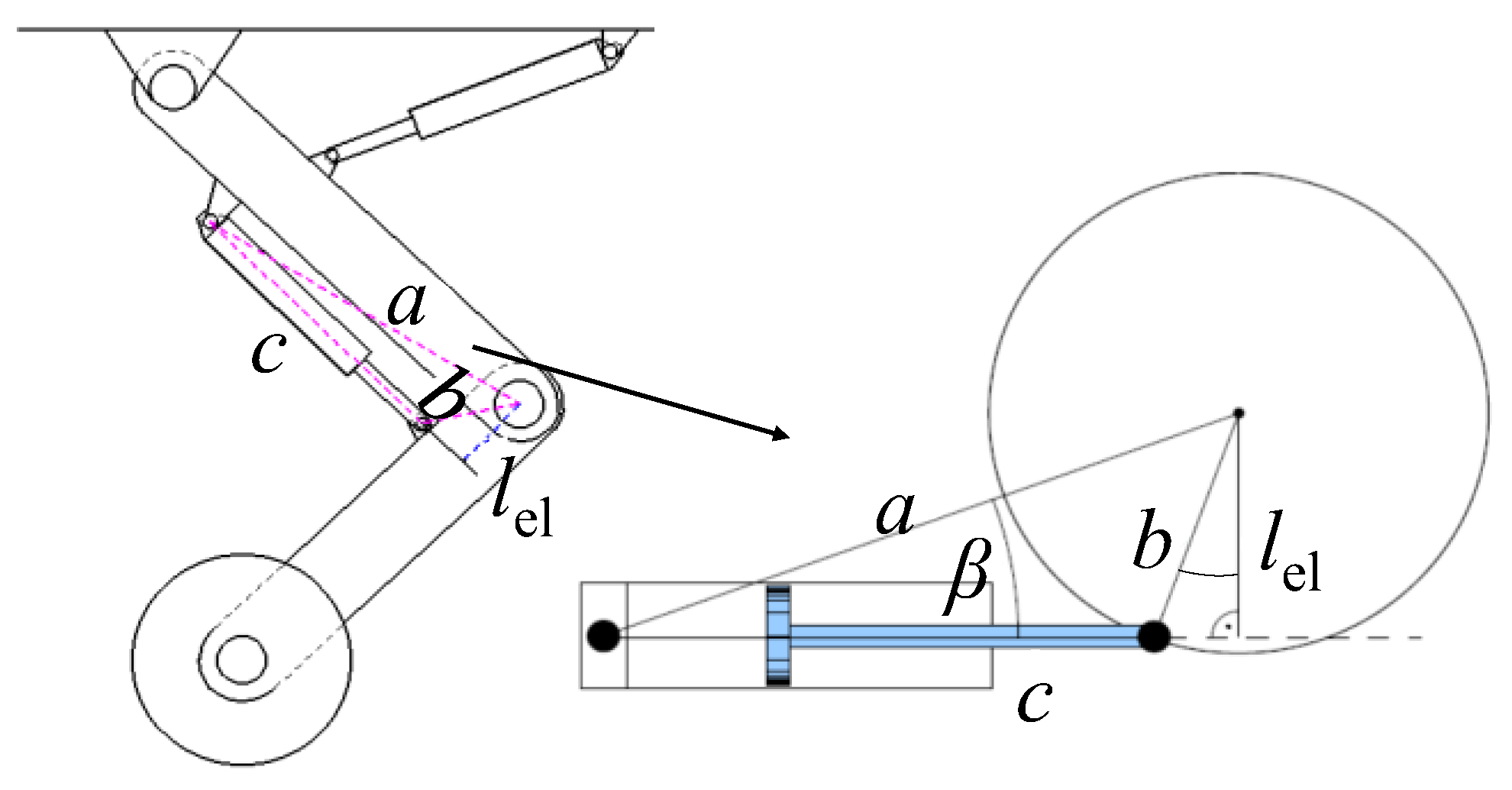
Figure 3.
Mechanical structure of EHA.
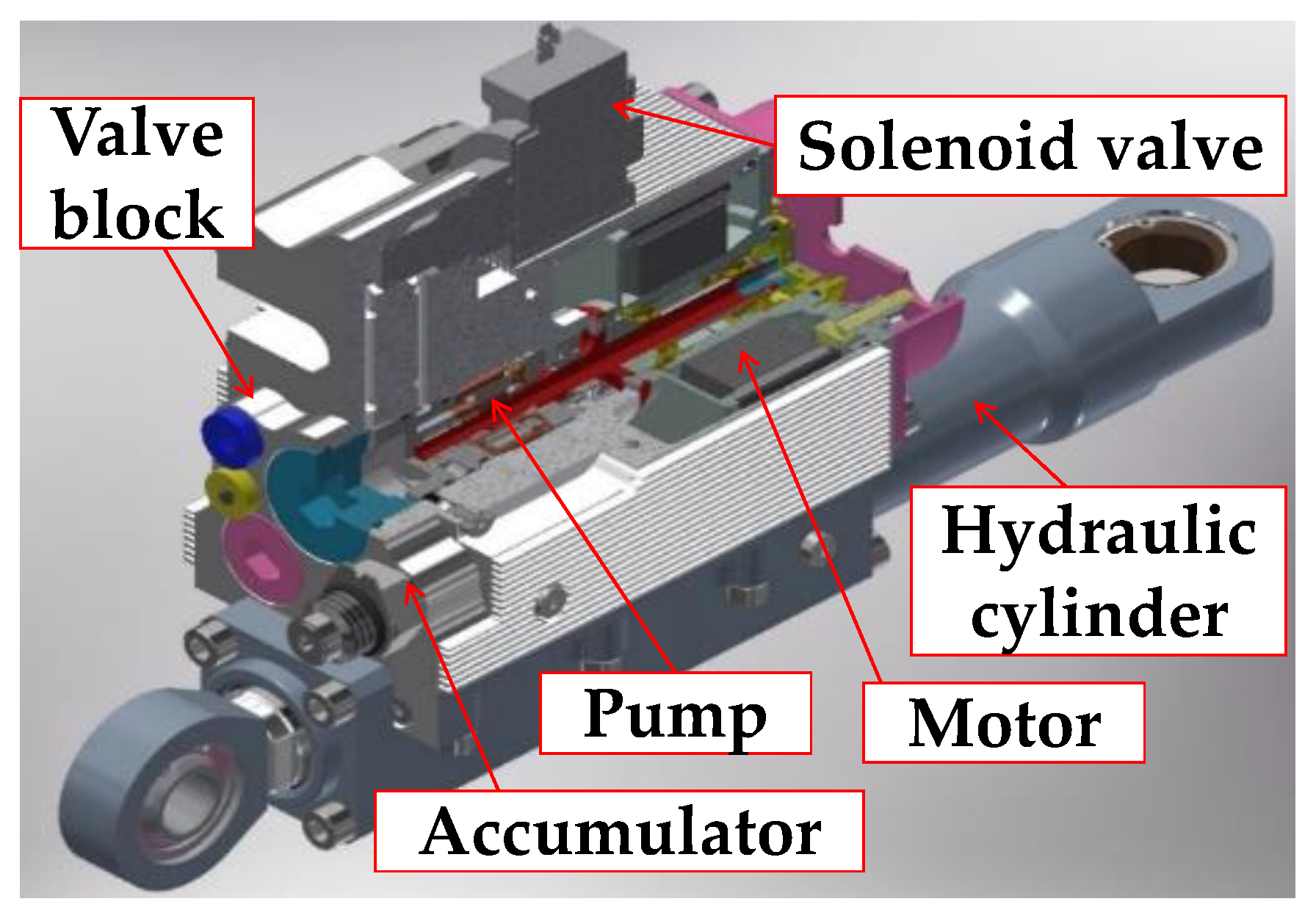
Figure 4.
Control block diagram of pressure controller.

Figure 5.
Control block diagram of position controller.
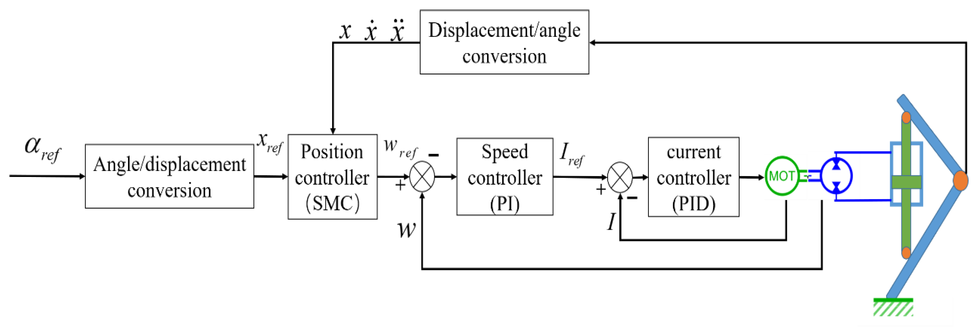
Figure 6.
EHA prototype.

Figure 7.
Test bench.
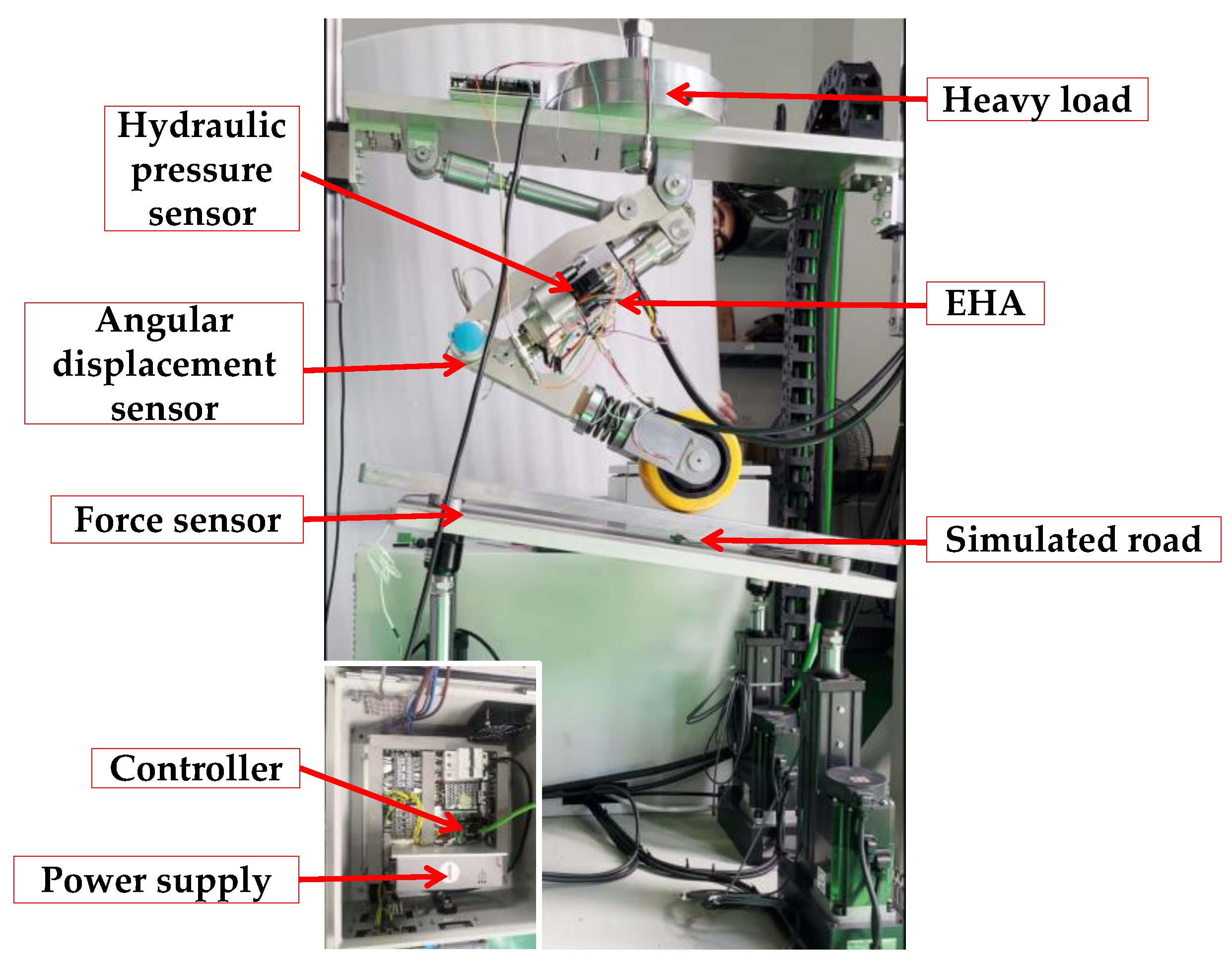
Figure 8.
Experiment and identification results.
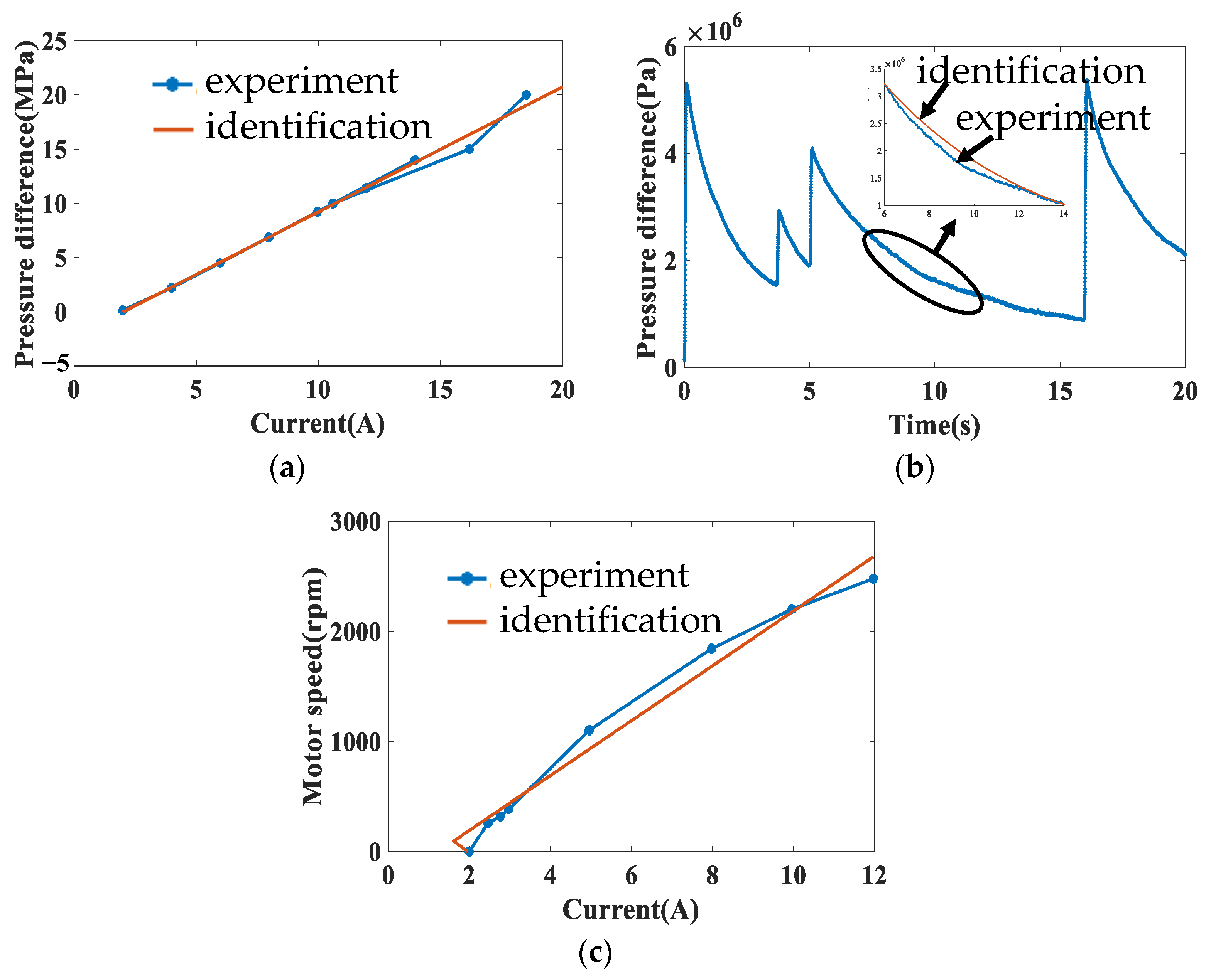
Figure 9.
Experimental and simulated step response of the pressure control system.(a) Step response of pressure 15 MPa; (b) motor current response with pressure 15 MPa; (c) step response of pressure 20 MPa; (d) motor current response with pressure 20 MPa; (e) step response of pressure 30 MPa; (f) motor current response with pressure 30 MPa.
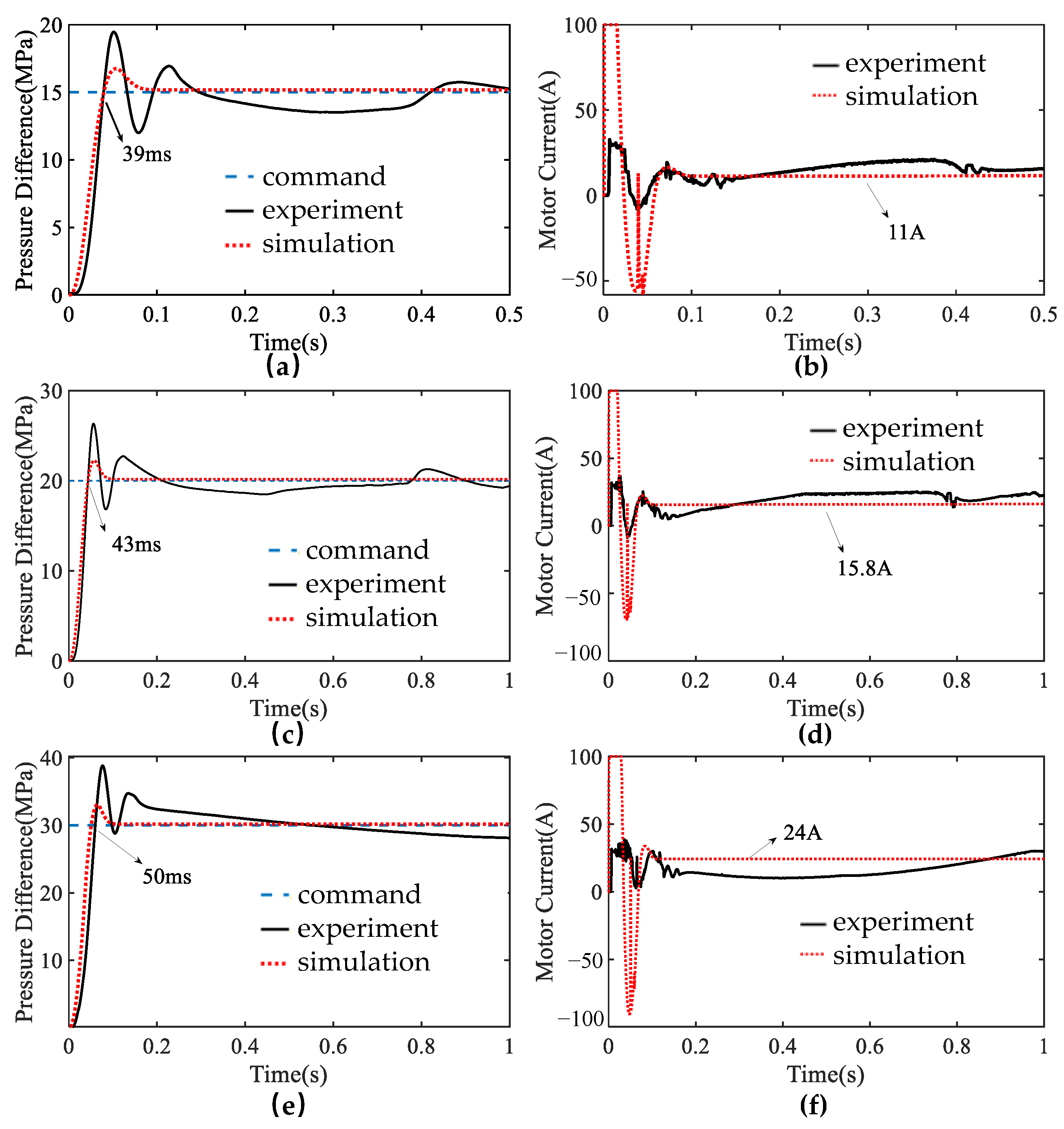
Figure 10.
Experimental and simulated sinusoidal response of the pressure control system. (a) Sinusoidal response of pressure amplitude 20 MPa and frequency 6.7 Hz; (b) motor current response with pressure amplitude 20 MPa and frequency 6.7 Hz; (c) sinusoidal response of pressure amplitude 30 MPa and frequency 6.7 Hz; (d) motor current response with pressure amplitude 30 MPa and frequency 6.7 Hz.

Figure 11.
Experimental and simulated response of the position control system. (a) Step response of angular displacement from 50° to 120°; (b) motor speed response with angular displacement from 50° to 120°; (c) sinusoidal response of angular displacement from 50° to 120° and frequency 1 Hz; (d) motor speed response with angular displacement from 50° to 120° and frequency 1 Hz.


Table 1.
Physical characteristics of the EHA prototype.
| Feature | Value | Unit |
|---|---|---|
| Weight | 3.694 | |
| Length | 290 | |
| Width | 170 | |
| Height | 70 |
Table 2.
Comparison of force-to-weight ratio with other EHA of robots.
| EHA of Robots | Force-to-Weight Ratio |
|---|---|
| This article | 2518 |
| Hydra | 1424 |
| Kaleido | 1500~2000 |
Table 3.
Identified model parameter values.
| Variable | Value | Unit |
|---|---|---|
| 0.13 | ||
| 0.003 | ||
| 0.00498 | ||
| 0.16 | ||
| 0.2537 | ||
| 2.0084 × 10⁻¹⁵ | ||
| 0.69 | ||
| 900 | ||
| 1.2535 × 10⁻⁵ | ||
| 1.2535 × 10⁻⁵ | ||
| 3.1337 × 10⁻⁵ | ||
| 9400 | ||
| 320.8 | mm | |
| 46.2 | mm | |
| 280 | mm |
Disclaimer/Publisher’s Note: The statements, opinions and data contained in all publications are solely those of the individual author(s) and contributor(s) and not of MDPI and/or the editor(s). MDPI and/or the editor(s) disclaim responsibility for any injury to people or property resulting from any ideas, methods, instructions or products referred to in the content. |
© 2023 by the authors. Licensee MDPI, Basel, Switzerland. This article is an open access article distributed under the terms and conditions of the Creative Commons Attribution (CC BY) license (https://creativecommons.org/licenses/by/4.0/).
Share and Cite
MDPI and ACS Style
Zhao, H.; Zhou, J.; Ma, S.; Du, S.; Liu, H.; Han, L. Design and Experiments of Electro-Hydrostatic Actuator for Wheel-Legged Robot with Fast Force Control Response. Machines 2023, 11, 685. https://doi.org/10.3390/machines11070685
AMA Style
Zhao H, Zhou J, Ma S, Du S, Liu H, Han L. Design and Experiments of Electro-Hydrostatic Actuator for Wheel-Legged Robot with Fast Force Control Response. Machines. 2023; 11(7):685. https://doi.org/10.3390/machines11070685
Chicago/Turabian StyleZhao, Huipeng, Junjie Zhou, Sanxi Ma, Shanxiao Du, Hui Liu, and Lijin Han. 2023. "Design and Experiments of Electro-Hydrostatic Actuator for Wheel-Legged Robot with Fast Force Control Response" Machines 11, no. 7: 685. https://doi.org/10.3390/machines11070685
Note that from the first issue of 2016, this journal uses article numbers instead of page numbers. See further details here.