

Study of the Transmission Characteristics of the Cycloid Gear Based on a Multi-Objective Optimization Modification
School of Mechanical Engineering, Dalian Jiaotong University, Dalian 116028, China
*
Author to whom correspondence should be addressed.
Machines 2023, 11(8), 775; https://doi.org/10.3390/machines11080775
Submission received: 27 June 2023
/
Revised: 18 July 2023
/
Accepted: 24 July 2023
/
Published: 25 July 2023
(This article belongs to the Special Issue Research on Rotor Dynamics and Vibration Control)
Abstract
:Due to the advantages of high transmission accuracy and high impact resistance, cycloid-pin gear drives are widely used in precision machinery. In the actual manufacturing and use process, a suitable clearance must be left between the cycloid gear and the pin teeth to meet the requirements of assembly lubrication, so the cycloid gear needs to be modified. In order to improve the performance of the cycloid-pin gear drive, this paper proposes a multi-objective optimization modification method which takes into account the maximum transmission error of the cycloid drive on the basis of the compound modification. Firstly, a compound modification function is constructed based on the equations of the cycloid gear. Tooth contact analysis is carried out on the cycloid gear to obtain the equations for calculating the transmission error and return error of the cycloid pinion drive and to solve for the transmission error and return error of a single cycle with different modification coefficients. Then, a multi-objective optimization model is constructed, and the optimum coefficients are solved by genetic algorithm. By analyzing the forces on the cycloid gear under load, the range, the number and the contact force of meshing teeth are calculated for different modification methods. At the end, the cycloid gear is modeled and finite element analyzed after multi-objective optimization modification and compound modification according to the optimal modification coefficients. By finite element analysis, the correctness of the theoretical calculation of the contact force of the modified cycloid gear and the loading transmission error is solved. The contact forces and transmission error of the multi-objective optimization modification are less than the compound modification. The theoretical calculation and finite element analysis indicate that the cycloid profile with the multi-objective optimization modification is better than the profile with the compound modification.
1. Introduction
The cycloid drive is widely applied to the high-precision reducer, which has the characteristics of high transmission precision and long service life. Because a cycloid drive has the advantages of a large reduction ratio, rigid and compact construction, high transmission accuracy and high shock-resistant ability, the application of a cycloid drive in industrial robots, machine tools and wind power has attracted more and more attention [1,2,3]. As a key part of the RV reducer, the cycloid gear has a vital effect on the transmission accuracy, efficiency, service life and other performance of the entire reducer. In the manufacturing and use process, it is necessary to leave a reasonable gap between the cycloid gear and the pin teeth in order to facilitate disassembly and lubrication [4]. Therefore, the cycloid gear should be modified.
Many scholars have conducted relevant research on the tooth modification of cycloid gears. Guan [5] proposed a compound modification method of negative pin position modification and positive pin radius modification to obtain the optimal modified tooth profile, and they deduced the equation of optimal modification amount. Ding et al. [6] proposed a cycloid gear profile modification method based on the compound modification method of negative pin position modification and positive pin radius, homogenizing tooth contact stresses while maintaining transmission accuracy, which can effectively improve the service life of the RV reducer. Ren et al. [7] proposed a new method for cycloid gear tooth modification. The main idea is to design modification clearance curves to adapt different modification targets. Zhang et al. [8] proposed a compound modification method of eccentricity, pin position and pin radius, and they confirmed its feasibility. These methods use a combination of modification methods, including pin position modification, pin radius modification and rotation angle modification. In addition to the compound modification method, some scholars have also made more attempts on complex cycloid profile designs. Based on the parabolic modification method, An et al. [9] adopted the reverse active modification method with tooth contact analysis and obtained a tooth profile that is more in line with engineering. Jiang et al. [10] proposed a vector correction method to achieve single-point partial correction instead of correcting all tooth profile points at the same time. Chen et al. [11] proposed an exponential function modification method based on the idea of segmental modification, which can improve the strength and meshing stiffness of the cycloid gear while ensuring the stability and accuracy of meshing. Zhang et al. [12] constructed a new topological modification method by dividing the tooth profile into working and non-working sections, using a combination of rotation angle modification and variable pin radius modification. Its rationality was verified from several perspectives. Gong et al. [13] proposed a modification method based on CNC form grinding technology, which fits the conjugate tooth profile better than the conventional method. Sun et al. [14] proposed a method based on parabola modification, which considered the transmission error and used the particle swarm optimization algorithm to solve the optimization coefficients. For cycloid gear profile modification, the idea of segmental modification can be used to avoid the problem that the compound modification method has large coefficients of modification and thus increases the transmission error. However, it is more difficult to machine the cycloid gear profile. The machining process has a large impact on the performance of the part [15,16,17].
In addition to researching new modification methods, analysis of the cycloid drive performance is also required. Many scholars have conducted research on the transmission errors and contact conditions of cycloid gears. Lei et al. [18] carried out finite element analysis on RV reducers and Spinea reducers in an attempt to reveal the static characteristics due to the different structures. Yu et al. [19] used a non-Hertzian elastic contact method to establish an equation based on the elastic deformation of the gear teeth and the flexibility of the load distribution to calculate the load distribution of the tooth profile more accurately. Liang et al. [20] constructed a gear tooth contact analysis model of the cycloid drive, by which they solved the instantaneous meshing state and meshing area of the cycloid drive under the conventional modification method. The transmission error curve and return error curve are also obtained. Li et al. [21] proposed an improved load distribution model of the mismatched cycloid-pin gear pair with ring pin position deviations for a component-level analysis, verified the correctness of the proposed model, and demonstrated the impact of ring pin position deviation on the mismatched cycloid-pin gear pair. Xu et al. [22] proposed a model of cycloid drive dynamics considering bearings in order to analyze contact positions and calculate contact loads. Bo et al. [23] analyzed the maximum normal contact load on the teeth of cycloid gears on RV reducers with different modifications, developed a hybrid lubrication model and discussed the effects of normal load at the point of engagement, radius of curvature, radius of fillet and speed on lubrication conditions. Lin et al. [24] proposed an algorithm for tooth contact analysis of cycloid gear reducers based on the discretization of the cycloid gear profile, investigated the effect of tolerances on motion errors and optimized the tolerances of the design parameters. Yang and Blanche [25] analyzed the relationship between machining tolerances, drive parameters and transmission performance parameters. Li et al. [26] proposed a model for analyzing the performance of cycloid-pin reducers that can predict the loads on the various components of the reducer in the presence of clearance and eccentricity errors. Lin et al. [27] designed a new cycloidal reducer and analyzed the transmission errors using tooth contact analysis after modification and gave quantitative results caused by different compound modifications. Han et al. [28] carried out a global sensitivity analysis of the transmission accuracy of the RV gearbox drive mechanism and thus identified the effect of various errors on transmission accuracy. He et al. [29] developed a quasi-static load distribution model considering four tooth profile modification methods, and they demonstrated that the meshing backlash has a significant influence on the performance of cycloid drive.
Most of the modification methods proposed by these scholars are to ensure that the modified cycloid tooth profile is closer to the conjugate tooth profile by adapting a new tooth profile to ensure transmission accuracy, without solving the modification coefficients directly by transmission performance parameters, and some of the modification methods ignore the actual machining methods. The optimization algorithm is applied to tooth profile modification, which greatly reduces the difficulty of calculation and also provides new ideas for tooth profile optimization. The choice of a suitable modification method has a relatively important influence on its transmission performance. Compound modification methods aim to fit the tooth profile and cannot directly select the optimum modification coefficients by the main transmission performance parameters to ensure a smaller transmission error and better load-carrying capacity of the cycloid gear. Therefore, a multi-objective optimization modification method is proposed based on the compound modification of pin radius and pin position. The method is optimized for the compound modification and transmission error to reduce the cycloid transmission error and contact force after modification. The solution is solved by the multi-objective genetic algorithm. Finite element analysis is used to verify the contact force and engagement range of the modified cycloid gear and to solve for the loaded cycloid drive error. The results of the multi-objective optimization and the compound modification method are analyzed and discussed to illustrate the feasibility of multi-objective optimized modification.
2. Tooth Profile Equation and Modification of Cycloid Gear
The standard cycloid is conjugate to the pin tooth profile and has no clearance during engagement; the cycloid gear engages half of the pin tooth without clearance.
The main parameters of the cycloid profile equation are shown in Figure 1. The equation for a standard cycloid profile is as follows [16]:
The variable S is:
where rp is the radius of the center circle of the pin tooth, rrp is the radius of the pin tooth, zp is the number of pin teeth, zc is the number of teeth of the cycloid gear, iH is the relative transmission ratio of the cycloid gear and the pin gear, iH = zp/zc, φ is the angle of one pin tooth relative to the rotating arm, a is the eccentricity, and K1 is the short width coefficient of the cycloid gear, K1 = azp/rp. For the actual application of the cycloid drive system, in order to compensate for manufacturing errors, facilitate disassembly and ensure lubrication, there must be clearance between the cycloid and pin. Thus, we cannot use the standard tooth profile: the cycloid gear needs to be modified. At present, there are three main kinds of cycloid gear modification method. The modification of a rotated angle involves modifying the cycloid profile by turning the cycloid blank around its center at a slight angle. The rotation angle method is closer to the conjugate tooth profile, but it cannot leave a reasonable clearance in the tooth top and root position, so the commonly modification method is commonly used to adapt the profile of rotation angle modification by adding a small quantity of pin radius modification ∆rrp and pin position modification ∆rp. The tooth profile equation of compound modification is:
It is important to note that when the tooth profile equation has pin position modification, the short width coefficient K1 is azp/(rp + ∆rp).
Replace iHφ in Equations (1) and (2) with (iHφ + δ) to obtain the tooth profile equation of the rotation angle modification method, and the modification coefficient of rotated angle is δ. The equation for a cycloid profile with rotation angle modification is as follows:
2.1. Compound Modification Coefficients
For the purpose of leaving a reasonable clearance and maintaining the conjugate tooth profile, the compound modification coefficients are ∆rp and ∆rrp. The compound modification tooth profile should fit the profile of the rotation angle modification as closely as possible. The rotation angle modification coefficient ∆φ of 0.0005 rad was chosen as the target for the compound modification method to fit.
2.2. Constructing the Objective Function
Since the coefficient of rotation angle modification is already given, then the rotation angle modification profile can be determined. According to the tooth profile equation, the two curves are divided equally into m parts from the interval [0, π], so that m + 1 sets of coordinate points are obtained, and the closeness of the two curves is described by the average of the relative position deviations of all the corresponding coordinate points. Then, the objective function f1 can be obtained:
When f1(∆rp, ∆rrp) is the smallest, the optimum coefficients can be obtained.
2.3. Range of Variable Constraints
According to the literature [5], the radial clearance is ∆r = ∆rp + ∆rrp, and the best tooth profile can be obtained with a compound modification of “negative pin position modification + positive pin radius modification”. In this paper, ∆r is calculated as 0.005 mm, ∆rp < 0 and ∆rrp > 0. Also, as too much coefficient will increase the cycloid side clearance and thus affect the transmission accuracy, the pin radius modification ∣∆rrp∣ is limited to <0.2 mm [30].
3. The Theoretical Foundation of the Multi-Objective Optimization Method
The compound modification method is used to obtain the optimal profile coefficients by adapting the tooth profile. However, it is also necessary to calculate the transmission performance parameters of the profile to compare the advantages and disadvantages of the methods. The multi-objective optimization method takes the transmission error as the optimization objective to improve transmission accuracy. The equations for the calculation of transmission error are then obtained through theoretical analysis.
TCA is a computational approach for the position of the gear teeth when they are engaged in the drive without load, which was a concept first proposed by Gleason Works in the 1960s in the USA. This method can be used to calculate the change in the position of the cycloid gear during the drive of the cycloid when analyzing the drive of the pin gear as a means of analyzing the transmission error of the mechanism.
The literature [14,24] describes the equations of the cycloid-pin gear transmission. As is shown in Figure 2, the transmission model is established according to the motion relationship between the cycloid gear and pin teeth.
Here, the pin gear coordinate system is Sp and the cycloid coordinate system is Sc. If the coordinate system in which the pin gear is located is a fixed coordinate system and the coordinate system in which the cycloid is located changes position with motion, then the transformation of Sc into Sp has the transformation matrix Mcp.
Here, φci is the cycloid output angle and φin is the crank shaft input angle. The coordinate system in which the pin tooth is located is the default coordinate system, and the tooth profile equation in the coordinate system Sp can be expressed as:
The unitized normal vector equation for the pin tooth profile Equation (10) np(θpi) can be obtained by differentiating the pin tooth profile equation Rp(θpi), then crossing normal vector k of XOY plane and unitizing it. The equation is as follows:
where Rp is the pin tooth profile equation, and k is the unit normal vector of the XOY plane; k = [0,0,1]. The tooth profile equation of the cycloid gear in the coordinate system Sc can be expressed as:
Equation (12) is the standard equation for the cycloid gear and θci is the parametric angle of the cycloid gear, which takes values in the range (0, 2π). It should be noted that when the cycloid gear is modified, the tooth profile equation in Rc(θci) should be replaced by the corresponding tooth profile equation.
By differentiating the cycloid tooth profile Rc(θci), intersecting it with the XOY plane normal vector k and unitizing it, the unitized normal vector equation for the cycloid tooth profile equation nc(θci) can be obtained:
where Rc is the equation for the profile of the cycloid gear and k is the unit normal vector of the XOY plane, k = [0,0,1].
By transforming the coordinates, the points on the cycloid gear in the Sc coordinate system can be expressed as points in the Sp coordinate system. They can be written as:
where Lcp takes the 3 × 3 submatrix in the upper left corner of Mcp.
If the cycloid gear and pin tooth are meshing, then there exists a point both on the cycloid tooth profile and on the pin tooth profile. Since it is a no-load situation, there is only one contact point on the pair of meshing teeth, so the system of equations can be constructed:
The first formula in Equation (15) can be projected onto the x-axis and y-axis in the coordinate system Sp, from which two scalar equations can be obtained. Because the normal vector ncp and the normal vector np are both unitized, a normal vector projection equation on x-axes can be obtained. Thus, the system of equations in Equation (15) consists of three equations. Given one of the parameters, the other three unknowns parameters can be solved by the system of Equation (15).
In the process of solving, since the transmission error of the cycloid-pin gear has a period, the size is 2π/zp [12]. The cycloid drive error has a period of size 2π/zp [14]. The equation of the cycloid gear expresses only one tooth. In this paper, the x-coordinate of the pinto equation is translated by a distance along the negative direction of the x-axis in order to facilitate calculations. The distance size is eccentric distance a. This makes it easier to determine the meshing range of the cycloid gear with the pin tooth. If so, the displacement transformation of the coordinate transformation matrix Mcp in the direction of the x-axis also requires translation by a displacement of one eccentric distance a in the negative direction of the x-axis.
The transmission error is the difference between the actual output angle and the theoretical output angle. Reducing the transmission error improves the transmission accuracy. The output angle is needed to calculate the transmission error, and the angular parameters of the cycloid and pin tooth profile at the point of engagement cannot be determined. The cycloid angle φout at each moment of engagement can be solved by giving the crank shaft input angle φin a certain number of steps. When solving Equation (15), it is important to note that there are cases where the solution results in interference between the cycloid and the pin teeth, which can be avoided by adjusting the initial value of the solution to the system of equations several times.
The transmission error TE can be calculated using Equation (16):
where φout is the actual output angle, i.e., the cycloid output angle φci, and r is the reduction ratio, r = zc.
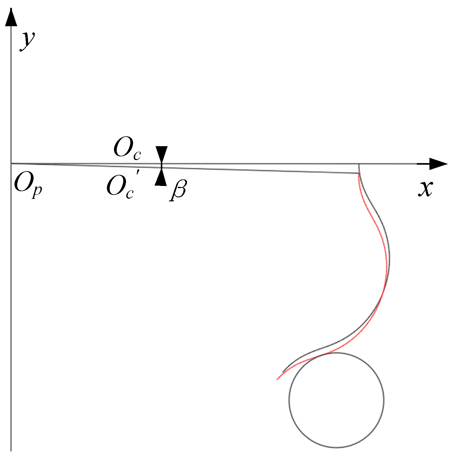
When calculating the transmission error, the moment when the cycloid gear enters into engagement needs to be considered. There is no clearance between the standard cycloid gear and the pin tooth mesh. The crankshaft needs to be turned through a certain angle to overcome the clearance and engage the cycloid with the pin tooth. Make an assumption based on TCA. If the crankshaft drives the modified cycloid under no load, when the cycloid is not yet in contact with the pin tooth, the crankshaft and the cycloid turn through the same angle, so that β is the angle of rotation of the cycloid from its initial position to enter engagement, as shown in Figure 3, and the red curve is the profile of the cycloid tooth that overcomes the clearance to just engage the pin tooth. When the cycloid gear is just engaged with the pin tooth, Equation (15) has a solution and φin = φci = β.
When the cycloid gear reverses its rotation, it also needs to overcome the clearance in order to engage the cycloid gear with the pin teeth, and the angle through which the cycloid gear turns in this process is referred to as the return error [31]. The cycloid gear rotates in reverse in its initial position and theoretically will also have an angle β to make it just overcome the clearance to engage the pin teeth, so the magnitude of the return error in this paper is taken as 2β.
4. Multi-Objective Optimization of Modification and Optimization Algorithms
The machining process for the compound modification method is more mature, and the coefficients of modification determine the machining parameters. The compound modification is based on pin radius modification and pin position modification, with the objective of fitting the profile of rotation angle modification. The main objective is to maintain a conjugate tooth profile on the tooth side and to leave a reasonable clearance at the root and top of the tooth. When comparing modification methods, it is usually based on transmission performance parameters. There is a wide range of solutions using genetic algorithms compared to empirical formulas. And it can better ensure that the solution set of the multi-objective optimization has diversity. The use of a multi-objective optimization algorithm to solve for the profile coefficients can further ensure the accuracy of the modified cycloid-pin gear, which is calculated on the basis of compound modification methods and transmission errors.
4.1. Constructing Optimization Functions
The equations for the transmission error and the compound modification profile of the pin tooth of the cycloid are known. When constructing the multi-objective optimization function, the maximum transmission error and the profile of angular rotation modification are taken as the optimization objectives. The multi-objective optimization function f2 is:
where the maximum transmission error TEmax and the compound modification function f1 are mutually constrained and cannot be taken to be the minimum of both at the same time. The optimization coefficients are ∆rp and ∆rrp.
4.2. Constraint Conditions
This multi-objective optimization modification method is constructed on the basis of the compound modification method. Therefore, the constraints are the same as for the compound modification method to control the radial clearance and facilitate comparison between the two methods. The radial clearance ∆r = ∆rp + ∆rrp, which is calculated by taking ∆r = 0.005 mm. In order to prevent excessive modification coefficients, pin radius modification ∣∆rrp∣ < 0.2 mm.
4.3. Optimization Algorithm
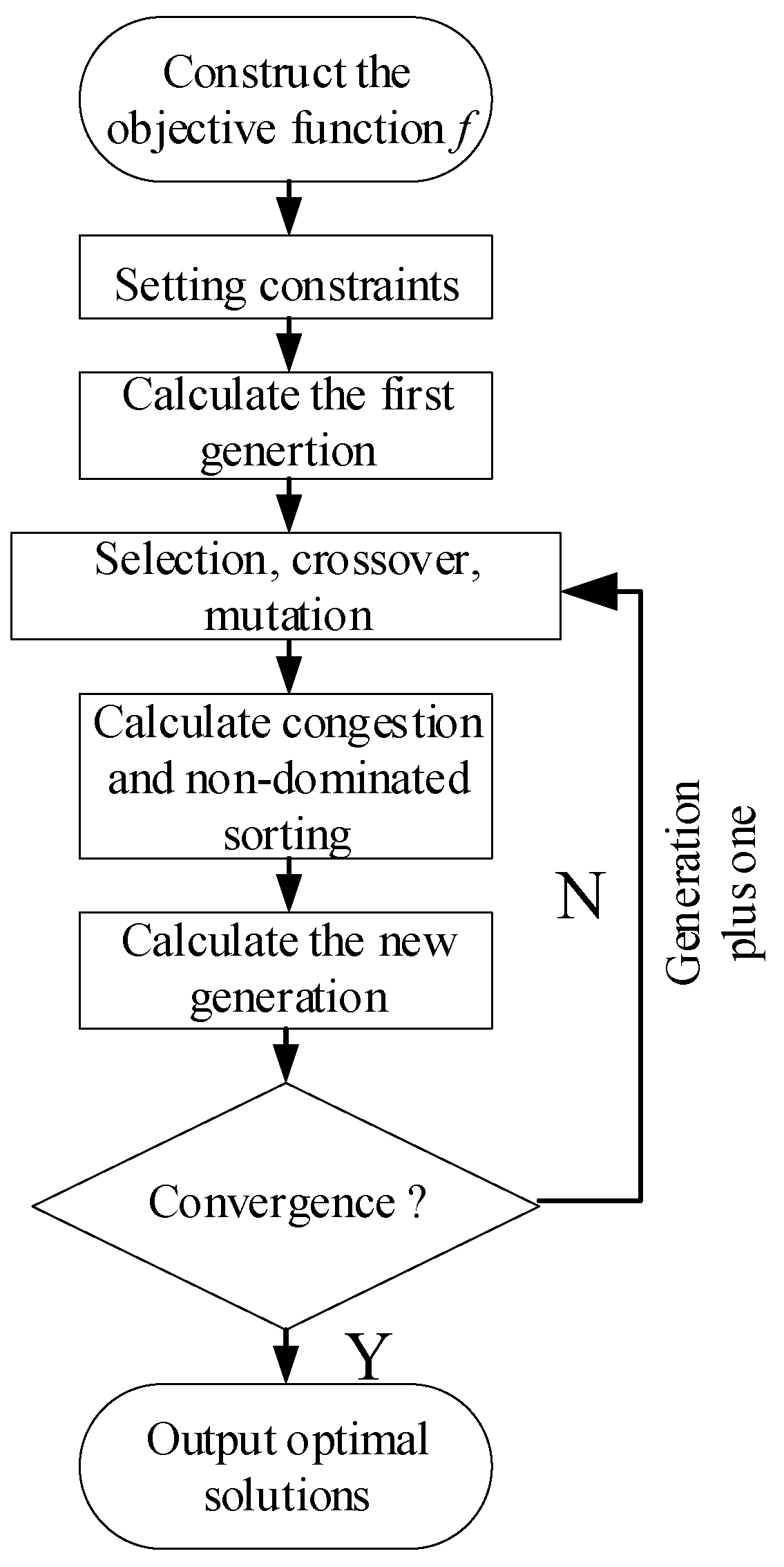
Genetic algorithms are a method of finding optimal solutions that mimic the evolution of natural organisms and can find optimal solutions in a global search relatively quickly. The genetic algorithm solution is not necessarily the same every time, and the optimal solution can be determined by solving multiple times. In this paper, a multi-objective genetic algorithm is used to solve for the optimal modification coefficients. The multi-objective genetic algorithm uses the operator of crowding to ensure the diversity of the solution set. The parameters for the solution of the multi-objective optimization algorithm in this paper are set as follows: the population size is 100, the optimal individual coefficient is 0.4, the maximum number of generations is 100, the crossover rate is 0.8, and the mutation rate is 0.1. The flow chart of the algorithm is shown in Figure 4. The compound modification uses a single-objective genetic algorithm, and the optimization process does not have the operator of crowding.
4.4. Optimization Example
The parameters of the cycloid gear analyzed in this paper are shown in Table 1.
To solve for the modification coefficients using the empirical formula [5], the equation can be referred to as follows:
According to Equations (18) and (19), ∆rrp = 0.0157 mm and ∆rp = −0.0107 mm can be obtained. And according to the genetic algorithm, ∆rrp = 0.0081 mm and ∆rp = −0.0031 mm, which is smaller than the modification coefficients of empirical formula. This is beneficial for improving the transmission accuracy. So, in this paper, the combined trimming and multi-objective optimized trimming coefficients are derived from the genetic algorithm.
Case a. The compound modification method with the objective of adapting the modification profile of the rotated angle is solved by the genetic algorithm. The objective function is Equation (8) f1(∆rp, ∆rrp).
Case b. The multi-objective optimization modification method with the objective of maximum transmission error and maximum contact force is solved by the genetic algorithm. The objective function is Equation (30) f2(∆rp, ∆rrp).
As is shown in Figure 5, the compound modification is relatively fast, converging after approximately 10 generations using the genetic algorithm, and satisfying the stopping condition in approximately 50 generations. The result obtained from Case b is a set of Pareto solutions. A pair of these modifying coefficients is selected in Table 2. Figure 6 shows a plot of the Pareto optimal solutions obtained by Case b.
The Pareto optimal solution should be a point diagram with an overall uniform distribution in general. The graph shows that the contact force and transmission error are mutually constrained: as one becomes smaller, the other must become larger. The uniform distribution of the scattered points indicates that the multi-objective optimization results are reliable.
Figure 7 shows a comparison of the modification profiles. It can be seen that the profiles of Cases a and b have a good fit with the profile of the rotation angle modification. The difference in normal clearance between the two methods is not significant, and a certain amount of radial clearance is left at the top and root of the tooth. The tooth profiles obtained by two cases are similar in position, but the profile of Case a is closer to the profile of the rotation angle modification. Case b is better than Case a in terms of transmission errors and contact forces. This shows that the closeness of a cycloid profile to the rotation angle profile does not necessarily mean better transmission performance. The advantages and disadvantages of the methods should also be compared according to the specific transmission performance parameters.
Excluding the effect of errors, solving Equation (15) for the modified cycloid gear profiles and then bringing the result into Equation (16) can find one period of transmission error for a single tooth, and by translating the angle of one period 2π/zc [27], the transmission error curve for one period under no load can be obtained. The change in transmission error as the crankshaft turns through one revolution is usually taken as a small period of the cycloid-pin drive. As shown in Figure 8, Figure 8a can be obtained by translating Figure 8b.
In Figure 8b, the intersection of the cycle curves gives the minimum value of the transmission error. The absolute value of the minimum transmission error for multi-objective optimization is 0.2374′ and that of compound modification is 0.2936′. The absolute value of the minimum transmission error reduces 19.1% compared to the compound modification. According to Equation (16), the return errors of the multi-objective optimization and the compound modification are, respectively, 1.15′ and 1.92′. The return error of multi-objective optimization reduces 19.5% compared to the compound modification.
5. Cycloid-Pin Gear Contact Force and Engagement Range
5.1. Theoretical Force Model
The contact forces between the cycloid gear and the pin teeth affect the performance of the cycloid-pin drive in terms of load-carrying capacity, service time, etc. The multi-objective optimization modification in this paper needs to consider the maximum contact force during the cycloid-pin drive. The contact forces between the cycloid gear and the pin teeth are shown in Figure 9, and the figure shows the standard cycloid gear.
The modified cycloid tooth profile no longer engages half of the pin teeth at the same time. In the case of no load, when one of the pin teeth is in contact with the cycloid, there is an initial clearance between the other pin teeth and the cycloid. When loaded, the tooth profile of the cycloid is deformed so that it engages with more pin teeth. We compare the initial clearance with the deformation of the cycloid tooth. When the cycloid gear tooth deformation δ is greater than the initial clearance, then the tooth is engaged under force; otherwise, there is no engagement. According to the literature [32], the initial gap ∆(φ)i of the cycloid gear is:
where φi is the rotation angle of the i-th pin tooth relative to the rotating arm OcOp. The pin tooth number can.be referred to Figure 9.
When the cycloid drive system works under load, let the maximum pair of cycloid contact deformation Wmax and the bending deformation of the pin teeth fmax sum up to δmax; then, the contact deformation of the i-th tooth is δi as:
where is the radius of the cycloid pitch circle, and li is the distance from the common normal of the i-th pin tooth engagement point or the normal of the point to be engaged to the center of the cycloid gear Oc. li can be expressed as:
When the contact deformation δi is greater than the initial gap ∆(φi), the i-th tooth is in meshing.
Assume that the force between the i-th pair of teeth is Fi, proportional to the actual deformation δi − ∆(φi) of the teeth in meshing, so:
Fmax is the contact force of the tooth with the highest force among the meshing teeth, which can be obtained from the moment balance equation:
where Tc is the torque on a single cycloid gear, and the torque magnitude is the same as the output torque of the cycloid gear. Taking Fi into equation Tc, Fmax is:
where Tc is 0.55T and T is the torque applied to the output shaft.
The total contact deformation δmax of the most stressed pair of meshing teeth under the force Fmax is:
Under the effect of Tc, the maximum contact deformation is Wmax, which is calculated by the equation as follows:
where v is the Poisson’s ratio of the material. For bearing steel, v is 0.3; E is the modulus of elasticity of the material, E = 2.06 × 10⁵ MPa. c is the axial clearance between the cycloid gear and the pin tooth casing. ρ is the radius of curvature of the cycloid gear profile, and it can be calculated by equations as follows:
fmax is the maximum contact deformation of the pin tooth and is calculated by the equation as follows:
where J is the moment of inertia of the section, L is the distance between the two pivot points of the pin, and the equation for calculating J is:
where dsp is the diameter of the pin tooth. In this paper, the pin tooth contact deformation fmax is ignored, taking into account the calculation model.
Equation (21) shows that it is necessary to know δmax and the mesh tooth number to solve Fmax, and according to Equations (25)–(27), it is necessary to know Fmax to solve δmax. δmax and Fmax are mutually known variables, so it is necessary to give the initial value of Fmax firstly. The initial value Fmax0 is:
Substitute Fmax0 into the equation to solve δ0, then solve Fmax1. Iterate until the Fmaxk obtained in the k-th iteration satisfies the condition ∣Fmaxk-Fmax(k−1)∣ < 0.1%Fmaxk; then, take Fmax = 1/2(Fmaxk + Fmax(k−1)) as the exact value to use. For the iteration flow chart, refer to Figure 10.
5.2. Calculation Example
The initial clearance and deformation of the cycloid gear can be obtained by substituting the modification coefficients of the multi-objective optimization and compound modification into the equation and calculating them according to the iterative process in Figure 10. Figure 11 shows the initial clearance and deformation curves for the two modification methods. The intersection of the initial clearance and deformation curves can be used to determine the meshing range of the modified tooth profile. The maximum deformation of the multi-objective optimized profile is greater than that of the compound modification profile, and the initial clearance is less than that of the compound modification profile.
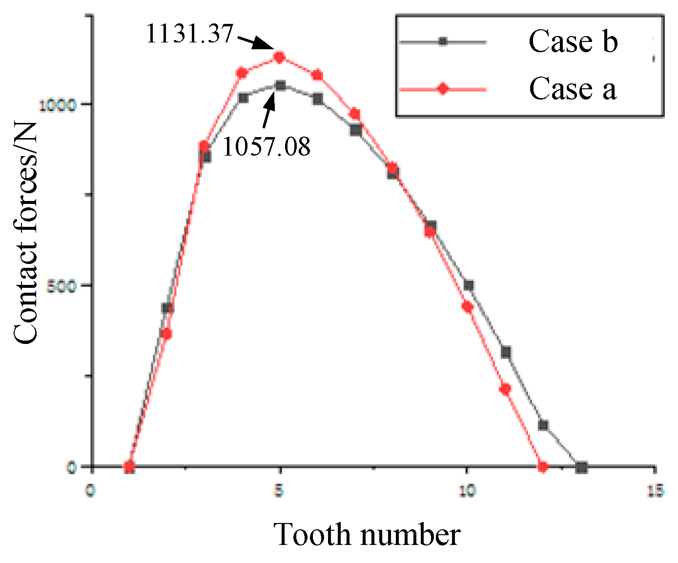
According to the range of teeth engaged, the contact force is calculated for the contact pair in the engagement range. The comparison of the contact forces between the two methods is shown in Figure 12.
Here, the multi-objective optimized profile has a higher number of teeth in contact and therefore a lower maximum contact force. The maximum contact force is 1057.08 N for the multi-objective optimized profile and 1131.37 N for the compound modification profile, showing a reduction of 6.6% in the maximum contact force.
6. Finite Element Analysis
6.1. Establishment of the Static Model
The contact forces of the cycloid drive can be verified with a static finite element model. The model mesh is shown in Figure 13. Only one piece of the cycloid gear is retained in the static analysis model, and the width of the cycloid gear is the same as the length of the pin teeth. In this paper, we mainly analyze the contact area of the cycloid gear. While the cycloid drive process is a dynamic process, for all pin teeth, as soon as they enter the engagement interval, they become the first contact teeth [33]. For this process, only one particular position in the drive needs to be analyzed to view the contact forces during the drive. The analysis in this paper is of the position where the cycloid gear overcomes the gap and just makes contact with the pin tooth under the action of the torque. The material of both the cycloid gear and the pin tooth is set to bearing steel, with a material modulus of elasticity E = 2.06 × 10¹¹ MPa, Poisson’s ratio of 0.3 and a density of 7850 kg/m3. According to the principle of motion of the cycloid-pin gear drive, the motion process can be approximated as a moment in which the cycloid gear rotates freely along the circumference of the eccentric axis, the pin tooth is fixed, and the cycloid gear rotates in contact with the pin tooth and transmits the motion [33]. The transmission load acts on the cycloid gear, and the model applies a transmission torque T = 420 Nm.
6.2. Establishment of the Dynamic Model
The drive error after loading the cycloid can be obtained by dynamic finite element analysis with the parts and mesh of the model shown in Figure 14. The pin teeth are set as rigid bodies to save calculation time. The input speed of the crank shaft is increased from 0 to 10 rad/s at 0–1 s and kept constant at 10 rad/s at 1–2 s. The load on the output end cap is 420 Nm. The material is set to bearing steel with an elastic modulus E = 2.06 × 10¹¹ MPa, Poisson’s ratio of 0.3 and density of 7850 kg/m3. The error of the loaded cycloid drive can be obtained by extracting the angle of rotation of the crank shaft and the cycloid gear during the movement.
6.3. Analysis of Optimization Results
The contact forces obtained from the static analysis are extracted, and a comparison of the contact forces obtained by the two methods is shown in Figure 15. Figure 15a,b show the comparison of the theoretical contact forces and the finite element method contact forces for the two modification methods, respectively. This reflects the number of tooth pairs that were meshed after loading the tooth profile obtained by modification. Case a simultaneously engages 10 pairs of teeth from tooth numbers 2 to 11. Case b engages 11 pairs of teeth from 2 to 12. The higher contact forces for both methods are concentrated on teeth 4, 5 and 6, with the maximum contact forces for Case b being somewhat lower. The overall trend of the results is similar to the theoretical calculation results, so the correctness of the theoretical calculation results can be verified.
Figure 16 shows the contact stress clouds for the multi-objective optimization and the compound modification, respectively. The contact stress magnitudes are 375.78 MPa and 389.45 MPa, respectively, with a small difference in contact stresses. The positions of the higher contact stresses are on the three contact pairs 3, 4 and 5, where it can be seen that the contact stresses are relatively continuous and uniform. In the marginal parts of the engagement such as teeth 11 and 12, however, it can be seen that the contact stresses are no longer partially continuous and uniform. This indicates that the errors associated with the FEA are magnified during the iterative calculations, but the overall figure reflects the number of simultaneous engagements of the cycloid during the drive and the position of the first teeth involved in the transmission.
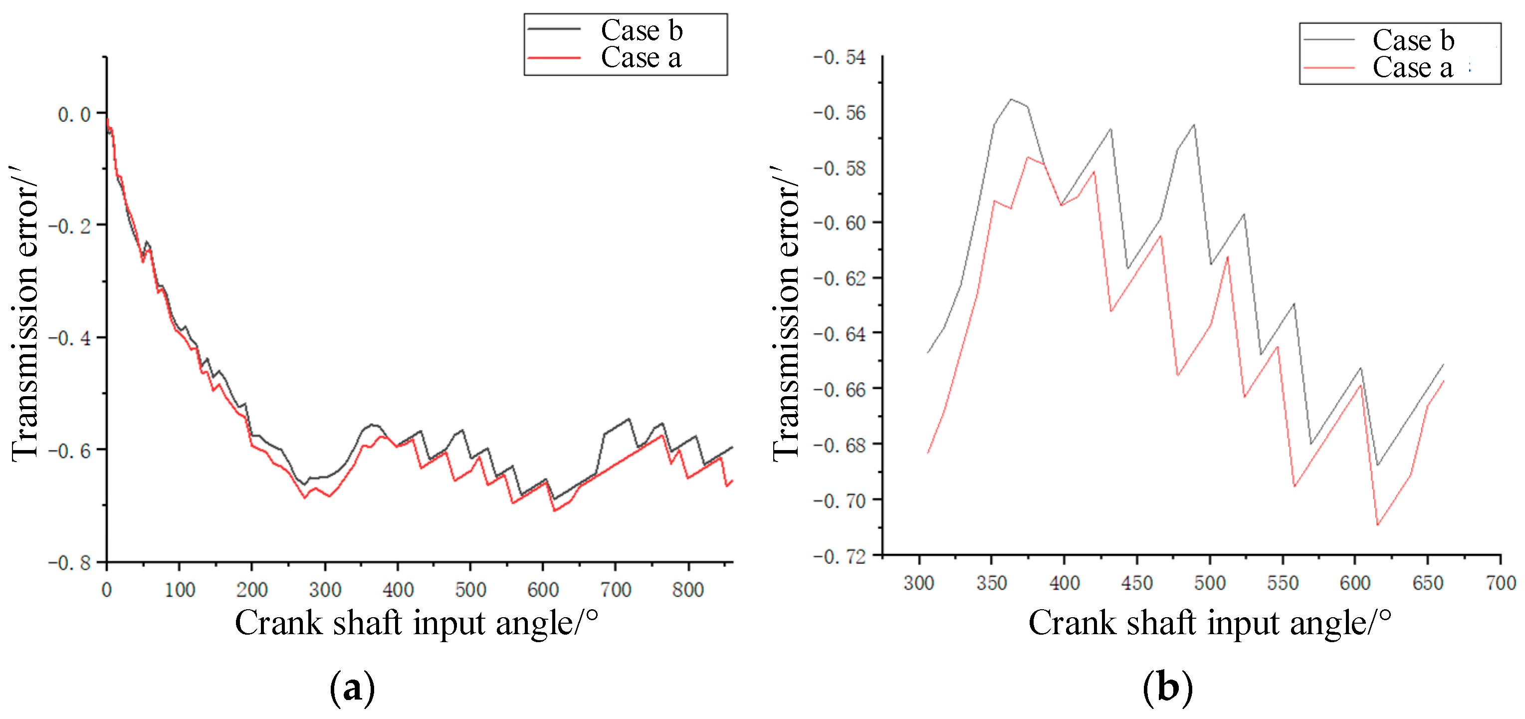
Deriving the angular displacement variations of the cycloid and crank shaft during the FEM dynamic analysis and calculating the transmission error according to Equation (16), the loading transmission error can be obtained as shown in Figure 17. Figure 17a is the transmission error by FEA.
Here, the speed of the crank shaft increases from 0 to 573.25°/s in 0–1 s and remains constant at 573.25°/s in 1–2 s. The mean value of transmission error was −0.608′ for the multi-objective optimization and −0.635′ for the compound modification in 1–2 s, with the mean transmission error for the multi-objective optimization being smaller in absolute value, reducing by 4.25%.
Table 3 shows the transmission performance parameters for two cases.
The return error and maximum contact force of the multi-objective optimization modification are smaller. The transmission errors of the multi-objective optimization modification are both less than 1′, so the results are reliable. Overall, Case b is better than Case a.
7. Conclusions
This paper presents a multi-objective optimization modification method that reduces the transmission error of the cycloid gear and increases the load-carrying capacity compared to compound modification. The multi-objective optimization modification method uses a genetic algorithm to solve the optimal modification coefficients, ensuring the diversity of the solution set. From this research, some conclusions can be summarized:
(1) The multi-objective optimized coefficients are solved by a multi-objective genetic algorithm on the basis of compound modification. The multi-objective optimization genetic algorithm solution set is homogeneous and is not influenced by the weight distribution of the optimization objectives.
(2) The modified profile of multi-objective optimization reduces the return error by 19.5%, the maximum contact force by 6.6% and the transmission error at no load by 19.1% compared to the compound modification, which is overall better than the compound modification.
(3) The finite element analysis results verify the theoretical contact force and engagement range, with similar trends in contact force and small differences in engagement range. The loading transmission error of the multi-objective optimization modification is overall smaller than that of the compound modification, and the average transmission error is reduced by 4.25% when the motion is stable.
(4) The modification coefficients and constraints are the same for the multi-objective optimization and the compound modification. The multi-objective optimized tooth profile has a better transmission performance. However, the compound modification profile is closer to the conjugate profile. This indicates that under certain conditions, the closeness to the conjugate profile does not necessarily mean higher transmission accuracy.
Author Contributions
Conceptualization, X.S.; methodology, X.S. and Y.C.; data curation, Y.C. and J.Y.; writing—original draft preparation, X.S. and Y.C.; writing—review and editing, X.S. and J.Y.; supervision, X.S., Y.C. and J.Y. All authors have read and agreed to the published version of the manuscript.
Funding
This work was supported by the National Natural Science Foundation of China (grant no. 51605069).
Data Availability Statement
The data used to support the findings of this study are included within the article.
Conflicts of Interest
The authors declare no conflict of interest.
References
- Sensinger, J.W. Unified approach to cycloid drive profile, stress, and efficiency optimization. J. Mech. Des. 2010, 132, 024503. [Google Scholar] [CrossRef]
- Wang, H.; Shi, Z.Y.; Yu, B.; Xu, H. Transmission performance analysis of RV reducers influenced by profile modification and load. Appl. Sci. 2019, 9, 4099. [Google Scholar] [CrossRef] [Green Version]
- Zhang, T.; Li, X.; Wang, Y.; Sun, L. A semi-analytical load distribution model for cycloid drives with tooth profile and longitudinal modifications. Appl. Sci. 2020, 10, 4859. [Google Scholar] [CrossRef]
- Wei, B.; Zhou, G.W.; Yang, R.S.; Zhou, H.J. Comparison Between Different Modification Model of Cycloidal Gear Used in RV Reduce. Mach. Des. Res. 2016, 32, 5. [Google Scholar]
- Guan, T.M. The Optimum Profile Modification on Cycloid Disks in the Cycloid Gearing Mechanism with Small Teeth Difference. China Mech. Eng. 2002, 10, 7–10+3. [Google Scholar]
- Ding, G.L.; Qin, Y.; Ming, T.B.; Zhao, D.X.; Yu, Y. Modification Method of Cycloid Gears Based on Contact Stress Equalization. China Mech. Eng. 2019, 30, 1081–1089. [Google Scholar]
- Ren, Z.Y.; Mao, S.M.; Guo, W.C.; Guo, Z. Tooth modification and dynamic performance of the cycloidal drive. Mech. Syst. Signal Process. 2017, 85, 857–866. [Google Scholar] [CrossRef]
- Zhang, F.S.; Yang, X.X.; Liu, J.T.; Li, P.F. Method of Cycloid Gear Tooth Profile Modification of RV Reducer. J. Mech. Transm. 2017, 41, 7–10. [Google Scholar]
- An, X.T.; Li, T.X.; Xing, C.R.; Wang, G.; Tian, M. Reverse Active Modification Method of Tooth Profile for RV Reducer Cycloidal Gear. J. Mech. Transm. 2019, 43, 81–86+165. [Google Scholar]
- Jiang, N.; Wang, S.; Xie, X.; Yuan, X.; Yang, A.; Zhang, J. A vectorial modification methodology based on an efficient and accurate cycloid tooth profile model. Precis. Eng. 2022, 73, 435–456. [Google Scholar] [CrossRef]
- Chen, X.W.; Zhu, M.; Wang, Q.L. Study on Contact Force and Transmission Accuracy of Cycloidal Wheel with exponential Modification. J. Mech. Transm. 2020, 44, 32–37. [Google Scholar]
- Zhang, L.F.; Su, J.X.; Shi, E.B.; Cheng, C. Study on topological modification of tooth profile of cycloid gear of RV reduce. Mach. Tool Hydraul. 2021, 49, 11–14. [Google Scholar]
- Gong, L.H.; Zuo, J.M. Piecewise Modification Methods of Cycloidal Gear in RV Reducer Based on the Form Grinding Technology. J. Mech. Strength 2020, 42, 5. [Google Scholar]
- Sun, X.; Han, L.; Wang, J. Tooth modification and loaded tooth contact analysis of China Bearing Reducer. Arch. Proc. Inst. Mech. Eng. Part C J. Mech. Eng. Sci. 1989–1996 2019, 233, 095440621985818. [Google Scholar] [CrossRef]
- Sun, Y.; Zheng, M.; Jiang, S.; Zhan, D.; Wang, R. A State-of-the-Art Review on Chatter Stability in Machining Thin−Walled Parts. Machines 2023, 11, 359. [Google Scholar] [CrossRef]
- Neugebauer, R.; Drossel, W.; Wertheim, R.; Hochmuth, C.; Dix, M. Resource and energy efficiency in machining using high-performance and hybrid processes. Procedia CIRP 2012, 1, 3–16. [Google Scholar] [CrossRef]
- Nguyen, D.N.; Dao, T.P.; Prakash, C.; Singh, S.; Pramanik, A.; Krolczyk, G.; Pruncu, C.I. Machining parameter optimization in shear thickening polishing of gear surfaces. J. Mater. Res. Technol. 2020, 9, 5112–5126. [Google Scholar] [CrossRef]
- Song, L.; Liang, S.; Li, W.; Chen, F. Comparison of the Key Structures Between RV Reducer and Spinea Reducer Based on Finite Element Method. In Application of Intelligent Systems in Multi-Modal Information Analytics; Springer International Publishing: Cham, Switzerland, 2019; pp. 1369–1374. [Google Scholar]
- Yu, H.L.; Yi, J.H.; Hu, X.; Shi, P. Study on teeth profile modification of cycloid reducer based on non-Hertz elastic contact analysis. Mech. Res. Commun. 2013, 48, 87–92. [Google Scholar] [CrossRef]
- Liang, S.F.; Deng, X.Z.; Li, T.X.; Wang, C.; Yang, J. Tooth Contact Analysis of Cycloidal Pinwheel Drive in RV Reducer of Robot. J. Mech. Transm. 2017, 41, 17–22. [Google Scholar]
- Li, X.; Tang, L.; He, H.; Sun, L. Design and Load Distribution Analysis of the Mismatched Cycloid-Pin Gear Pair in RV Speed Reducers. Machines 2022, 10, 672. [Google Scholar] [CrossRef]
- Xu, L.X.; Chen, B.K.; Li, C.Y. Dynamic modelling and contact analysis of bearing-cycloid-pinwheel transmission mechanisms used in joint rotate vector reducers. Mech. Mach. Theory 2019, 137, 432–458. [Google Scholar] [CrossRef]
- Wei, B.; Wang, J.X.; Zhou, G.W.; Yang, R.; Zhou, H.; He, T. Mixed lubrication analysis of modified cycloidal gear used in the RV reducer. Proc. Inst. Mech. Eng. Part J J. Eng. Tribol. 2016, 230, 121–134. [Google Scholar]
- Lin, K.S.; Chan, K.Y.; Lee, J.J. Kinematic error analysis and tolerance allocation of cycloidal gear reducers. Mech. Mach. Theory 2018, 124, 73–91. [Google Scholar] [CrossRef]
- Yang DC, H.; Blanche, J.G. Design and application guidelines for cycloid drives with machining tolerances. Mech. Mach. Theory 1990, 25, 487–501. [Google Scholar] [CrossRef]
- Li, X.; Li, C.; Wang, Y.; Chen, B. Analysis of a cycloid speed reducer considering tooth profile modification and clearance-fit output mechanism. J. Mech. Des. 2017, 139, 033303. [Google Scholar] [CrossRef]
- Lin, W.S.; Shih, Y.P.; Lee, J.J. Design of a two-stage cycloidal gear reducer with tooth modifications. Mech. Mach. Theory 2014, 79, 184–197. [Google Scholar] [CrossRef]
- Han, L.; Guo, F. Global sensitivity analysis of transmission accuracy for RV-type cycloid-pin drive. J. Mech. Sci. Technol. 2016, 30, 1225–1231. [Google Scholar] [CrossRef]
- He, H.; Li, X.; Zhang, T. Multi-Tooth Contact Analysis and Tooth Profile Modification Optimization for Cycloid Drives in Industrial Robots. Teh. Vjesn. 2023, 30, 93–101. [Google Scholar]
- Zhang, Z.Y.; Liu, L.; Luo, L.M.; Li, G.P.; Mo, X.L. Combined Modification an Optimization of Cycloid Wheel of RV Reducer. J. Ningbo Univ. (Nat. Sci. Eng. Ed.) 2022, 35, 5. [Google Scholar]
- Wu, Y.K.; Zheng, J.Y.; Chen, T.Q.; He, W.D. The Analysed Calculation of Geometric Lost Motion Cycloid Gear. J. Dalian Jiaotong Univ. 1999, 2, 28–32. [Google Scholar]
- Zhu, X.L. Handbook of Gear Design; Chemical Industry Press: Beijing, China, 2010; pp. 559–562. [Google Scholar]
- Lei, L.; Shi, X.C.; Guan, T.M. Finite Element Analysis for Cycloid Gear and pin Teeth of FA Cycloid Drive Based on ANSYS. Appl. Mech. Mater. 2012, 215–216, 1197–1200. [Google Scholar] [CrossRef]
Figure 1.
Cycloid-pin gear with equation parameters.

Figure 2.
Coordinate systems for tooth contact analysis.

Figure 3.
Return error of cycloid-pin gear drive.

Figure 4.
Genetic algorithm flow chart.

Figure 5.
Iteration diagram of the compound modification.

Figure 6.
Iteration diagram of the multi-objective optimization algorithm.

Figure 7.
Comparison of cycloid tooth profiles.

Figure 8.
Transmission error at no load: (a) Transmission error of a small period for cycloid-pin drive; (b) Part of the small period.
Figure 8.
Transmission error at no load: (a) Transmission error of a small period for cycloid-pin drive; (b) Part of the small period.

Figure 9.
Analysis diagram of contact force of cycloid gear.

Figure 10.
Flow chart of contact force iteration.

Figure 11.
Deformations and initial clearances: (a) Compound modification; (b) Multi-objective optimization modification.
Figure 11.
Deformations and initial clearances: (a) Compound modification; (b) Multi-objective optimization modification.

Figure 12.
Comparison of contact force.

Figure 13.
Finite element of the cycloid-pin gear.

Figure 14.
Dynamic analysis model for cycloid-pin gear: (a) Parts of dynamic finite element analysis; (b) Assembly model and mesh generation.
Figure 14.
Dynamic analysis model for cycloid-pin gear: (a) Parts of dynamic finite element analysis; (b) Assembly model and mesh generation.

Figure 15.
Comparison of contact forces for modified cycloid gears: (a) Compound modification; (b) Multi-objective optimization modification.
Figure 15.
Comparison of contact forces for modified cycloid gears: (a) Compound modification; (b) Multi-objective optimization modification.

Figure 16.
Contact stresses for modified cycloid gears: (a) Compound modification; (b) Multi-objective optimization modification.
Figure 16.
Contact stresses for modified cycloid gears: (a) Compound modification; (b) Multi-objective optimization modification.

Figure 17.
Comparison of loaded transmission error: (a) Transmission error by FEA; (b) Transmission error of a small period.
Figure 17.
Comparison of loaded transmission error: (a) Transmission error by FEA; (b) Transmission error of a small period.


Table 1.
Parameters table for cycloid gears.
| Parameter | Value | Unit |
|---|---|---|
| Pin center circle radius rp | 82 | mm |
| Pin radius rrp | 4 | mm |
| Eccentric distance a | 1.5 | mm |
| Cycloid gear teeth number zc | 39 | / |
| Pin number zp | 40 | / |
| Width of cycloid gear bc | 15 | mm |
Table 2.
Optimization coefficients of two case.
| Modification Method | Modification Coefficient ∆rp (mm) | Modification Coefficient ∆rrp (mm) |
|---|---|---|
| Case a | −0.0031 | 0.0081 |
| Case b | −0.0014 | 0.0073 |
Table 3.
Transmission performance parameters for the two modification methods.
| Modification Method | Return Error (Arcmin) | Maximum Contact Force (N) | No-Load Minimum Transmission Error (Arcmin) | Loaded Average Transmission Error (Arcmin) |
|---|---|---|---|---|
| Case a | 2.30 | 1131.37 | −0.25 | −0.64 |
| Case b | 1.92 | 1057.08 | −0.18 | −0.61 |
Disclaimer/Publisher’s Note: The statements, opinions and data contained in all publications are solely those of the individual author(s) and contributor(s) and not of MDPI and/or the editor(s). MDPI and/or the editor(s) disclaim responsibility for any injury to people or property resulting from any ideas, methods, instructions or products referred to in the content. |
© 2023 by the authors. Licensee MDPI, Basel, Switzerland. This article is an open access article distributed under the terms and conditions of the Creative Commons Attribution (CC BY) license (https://creativecommons.org/licenses/by/4.0/).
Share and Cite
MDPI and ACS Style
Song, X.; Chen, Y.; Yang, J. Study of the Transmission Characteristics of the Cycloid Gear Based on a Multi-Objective Optimization Modification. Machines 2023, 11, 775. https://doi.org/10.3390/machines11080775
AMA Style
Song X, Chen Y, Yang J. Study of the Transmission Characteristics of the Cycloid Gear Based on a Multi-Objective Optimization Modification. Machines. 2023; 11(8):775. https://doi.org/10.3390/machines11080775
Chicago/Turabian StyleSong, Xueping, Yang Chen, and Jianming Yang. 2023. "Study of the Transmission Characteristics of the Cycloid Gear Based on a Multi-Objective Optimization Modification" Machines 11, no. 8: 775. https://doi.org/10.3390/machines11080775
Note that from the first issue of 2016, this journal uses article numbers instead of page numbers. See further details here.