Abstract
This paper proposes a stator core design to achieve variable-flux characteristics enhanced by magnetic saturation in fractional-slot concentrated winding (FSCW) permanent-magnet (PM) motors without additional excitation systems, complicated structures, or active controls. Magnetic saturation induced at suitable locations can enhance variable-flux characteristics because the PM flux linkage is variable with the magnetic saturation in cores. In distributed winding configurations, magnetic saturation is induced symmetrically for each rotor pole by the fundamental that is dominant in the spatial distribution of the air-gap flux density. The magnetic saturation at each rotor pole can enhance variable-flux characteristics. In FSCW configurations, magnetic saturation is not induced symmetrically for each rotor pole because of several dominant space harmonics. The magnetic saturation at several rotor poles cannot enhance variable-flux characteristics. In the proposed design, the stator core has thin tooth tips for inducing magnetic saturation. The magnetic saturation in the stator core achieves the variable-flux characteristics that are effective for expanding the operating region or decreasing electromotive force and increasing torque. The efficacy of the proposed design is determined by estimating motor performance through a finite element method analysis and demonstrating the actual motor performance of a prototype.
1. Introduction
Variable-flux characteristics have been investigated as a design concept to achieve motor drives over a wide operating range of torque and speed in permanent-magnet (PM) motors [1]. High-torque, low-speed operation requires a high PM flux linkage to achieve high-torque production under an input current limit. Low-torque, high-speed operation requires a low PM flux linkage to achieve high-speed rotation under an input voltage limit. The variability of PM flux linkage in operation is realized through many design methods [1] such as field winding excitation [2,3], adjustable magnetization [4,5], and mechanical flux regulation [6,7,8]. However, these design methods require additional excitation systems, complicated structures, or active controls.
Variable leakage-flux motors have been proposed to achieve variable-flux characteristics without additional excitation systems, complicated structures, or active controls [9,10,11]. Such motors positively induce magnetic saturation in iron cores to vary the PM flux linkage of armature windings. The magnetic saturation is indirectly controlled with the q-axis current that is controlled for torque production. In high-torque operation, the magnetic saturation appears to enhance the PM flux linkage with a large q-axis current. In low-torque operation, the magnetic saturation does not appear to suppress the PM flux linkage with a small q-axis current. To realize these phenomena, magnetic paths, referred to as leakage-flux bypasses in [10], are established between adjacent PM poles for the leakage flux of PMs in the rotors. In high-torque operation, the large input current induces magnetic saturation around the leakage-flux bypasses. This leads to the suppression of the PM flux through the bypasses to enhance the PM flux linkage. In low-torque operation, the leakage-flux bypasses do not receive any influence, namely, magnetic saturation, because of the small input current. This allows for the PM flux to pass through the leakage-flux bypasses to suppress the PM flux linkage. The PM flux passing through the leakage-flux bypasses is regarded as the leakage of the PM flux. Therefore, such motors simply vary the PM flux linkage and expand the operating region without additional excitation systems, complicated structures, or active controls. This implies that magnetic saturation induced at suitable locations can enhance variable-flux characteristics.
Fractional-slot concentrated winding (FSCW) configurations have attracted much attention with the aim to achieve lower cogging torque, lower copper loss, and shorter axial length design than integral-slot distributed winding configurations in PM motors [12,13,14,15,16,17,18,19]. In FSCW configurations, the magnetic field, due to the armature windings, includes several dominant space harmonics. One of them produces drive torque. The others give rise to undesirable effects that increase iron loss in cores and eddy-current loss in PMs without contributing to torque production [20,21,22,23,24]. These dominant space harmonics induce magnetic saturation asymmetrically for each pole in rotor cores because of the different periodicities in the spatial distribution of the air-gap flux density.
This paper proposes a stator core design to achieve variable-flux characteristics enhanced by magnetic saturation in FSCW PM motors. Variable leakage-flux motors have been proposed in distributed winding configurations that generate a dominant space harmonic or fundamental [9,10,11]. The dominant space harmonic induces symmetrical magnetic saturation for each pole in the rotor cores. The magnetic saturation in the rotor cores contributes to the variable leakage-flux characteristics. For this reason, FSCW configurations with several dominant space harmonics do not effectively achieve the variable leakage-flux characteristics because magnetic saturation is induced asymmetrically for each pole in the rotor cores. In this paper, variable-flux characteristics are achieved through magnetic saturation in the stator core for a PM motor with a 12-slot 10-pole concentrated winding (CW) configuration as one of FSCW configurations. Therefore, the proposed design expands the operating region or decreases electromotive force (EMF) and increases torque without additional excitation systems, complicated structures, or active controls. The efficacy of the design concept is determined by estimating the PM flux linkage of armature windings, torque for q-axis current, and motor performance through a finite-element method (FEM) analysis and demonstrating the actual motor performance of a prototype.
2. A Leakage-Flux Bypass CW Motor
This section describes that variable leakage-flux characteristics are not effective for expanding the operating region of FSCW PM motors that employ a specific space harmonic except the fundamental for torque production in contrast to that of distributed winding PM motors. A 12-slot 10-pole CW motor whose rotor has leakage-flux bypasses, for example, is examined with respect to variable leakage-flux characteristics through an FEM analysis. Figure 1a and Figure 1b, respectively, show the cross sections of analyzed motors, namely, a 12-slot 10-pole CW motor with a conventional rotor, which is designated as CONV for comparison, and the motor with leakage-flux bypasses, which is designated as LFBP. The dimensions of the analyzed motors are presented in Table 1. The dimensions of the stator tooth tips are determined to suppress magnetic saturation at those locations. The thickness of the leakage-flux bypasses governs the no-load PM flux linkage or the no-load d-axis flux linkage and the variable leakage-flux characteristics. In this paper, a leakage-flux bypass thickness of is selected for comparison with CONV and the proposed design. The stator and rotor cores are constructed of electrical steel sheets 50JN470. The rotor PMs are made of neodymium magnet material NMX-44CH. The variable leakage-flux characteristics are determined from the d-axis flux linkage and torque for the q-axis current in reference to [10,11].
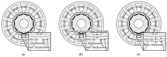
Figure 1.
Cross sections of 12-slot 10-pole PM motors that have (a) a conventional stator and a conventional rotor (CONV), (b) a conventional stator and a rotor with leakage-flux bypasses (LFBP), and (c) a proposed stator and a conventional rotor (PROP).

Table 1.
Dimensions of analyzed motors.
The leakage-flux bypasses ineffectively achieve variable leakage-flux characteristics in CW motors in contrast to distributed winding motors. Figure 2a shows the d-axis flux linkage for the q-axis current in CONV for comparison, where the q-axis current is calculated with the armature current and the current phase : . Each thin line denotes the d-axis flux linkage for the current phase , where the d-axis current is defined as at each armature current . The dashed line, which is designated as , indicates the value of d-axis flux linkage without armature current. The d-axis flux linkage slightly increases with the q-axis current at a current phase of or in the zero d-axis current operation. The maximum q-axis current increases the d-axis flux linkage by approximately . Figure 3a shows the d-axis flux linkage for the q-axis current in LFBP. The d-axis flux linkage increases with the q-axis current in the zero d-axis current operation. The maximum q-axis current increases the d-axis flux linkage by approximately . The motor LFBP exhibits a larger increase ratio of the d-axis flux linkage to the q-axis current than CONV. The larger increased ratio of the d-axis flux linkage is attributed to the PM flux linkage of armature windings enhanced by the magnetic saturation around several leakage-flux bypasses in LFBP. The increased d-axis flux linkage contributes to the enhancement in torque production in comparison with the situation without magnetic saturation. At the no-load condition or , the d-axis flux linkage of LFBP is lower than that of CONV by approximately . The leakage-flux bypasses significantly decrease the PM flux linkage of armature windings at the no-load condition. The PM flux partially passes through the leakage-flux bypasses not to pass through the armature winding coils. Even in CONV or a motor without the leakage-flux bypasses, the d-axis flux linkage slightly increases with the q-axis current because the rotor has flux paths corresponding to narrow leakage-flux bypasses near the air gap.
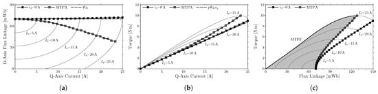
Figure 2.
Variable-flux characteristics of CONV: (a) d-axis flux linkage, (b) torque for q-axis current, and (c) torque for flux linkage.
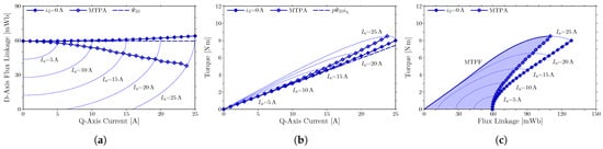
Figure 3.
Variable-flux characteristics of LFBP: (a) d-axis flux linkage, (b) torque for q-axis current, and (c) torque for flux linkage.
Figure 2b shows the torque for the q-axis current in the zero d-axis current operation in CONV. Each thin line denotes the torque for current phase at each armature current . In addition, the torque production without magnetic saturation, which is estimated using the number of pole pairs p, the no-load d-axis flux linkage as
is denoted by the dashed line. The comparison between these lines shows that the torque production is slightly enhanced by magnetic saturation with a large q-axis current. The maximum q-axis current increases the torque by approximately in comparison to the situation without magnetic saturation. Figure 3b shows the torque for the q-axis current in the zero d-axis current operation in LFBP. The comparison between the torques in the actual situation and in the situation without magnetic saturation shows that the torque production is enhanced by magnetic saturation with a large q-axis current. The maximum q-axis current increases the torque by approximately in comparison to the situation without magnetic saturation. The motor LFBP exhibits a larger enhancement in torque production by the q-axis current than CONV. Thus, the leakage-flux bypasses realize the so-called variable leakage-flux characteristics. However, the leakage-flux bypasses significantly decrease the PM flux linkage of armature windings and the torque production.
The variable leakage-flux characteristics are not effective for expanding the operating region in the CW motor LFBP. For motor drives over a wide range of torque and speed, motors should be operated to expand the operating region under an input current and voltage limit. The actual operating region of the motors CONV and LFBP is enclosed by the curve corresponding to the maximum torque per ampere (MTPA) operation, the curve corresponding to the maximum torque per flux-linkage (MTPF) operation, and the line for zero torque [25], as shown in Figure 2c and Figure 3c. Here, the flux linkage of armature windings is substituted for the rotational speed to clarify the MTPF operation curve. Because the flux linkage is hardly dependent on the rotational speed, the operating regions shown in Figure 2c and Figure 3c are calculated at a rotational speed of . The MTPA operation maximizes torque for an input current. The MTPF operation maximizes torque for a given flux linkage under an input current limit. The zero d-axis current operation is not included in the actual operating region. Therefore, the efficacy of the variable leakage-flux characteristics is determined from the actual operating regions in this paper. Figure 4 shows the actual operating regions in the flux linkage and torque of the motors CONV and LFBP. The variable-flux characteristics can be compared for these motors by matching the maximum torque. The operating region of LFBP is enlarged to to match the maximum torque with the motor CONV at an armature current of . This enlargement corresponds to the increase in the stack length from to in the machine design in LFBP. The actual operating regions of these motors appear in an almost identical area. Thus, the variable leakage-flux characteristics are not effective for expanding the actual operating region in the CW motor LFBP in spite of the large increased ratio of the d-axis flux linkage to the q-axis current.
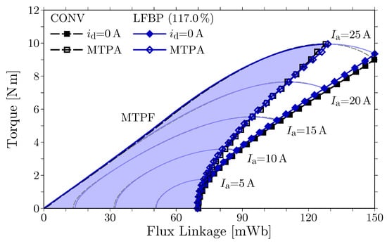
Figure 4.
Actual operating regions in the flux linkage and torque of CONV and LFBP.
The ineffectiveness in the variable leakage-flux characteristics is caused by non-identical magnetic saturation for each leakage-flux bypass. Figure 5 shows the distribution of magnetic flux density in the MTPA operation with and in LFBP. In FSCW configurations, the leakage-flux bypasses do not face an equivalent armature winding arrangement. The non-equivalent armature winding arrangements give magnetically different phenomena to leakage-flux bypasses. This causes differences in magnetic saturation at leakage-flux bypasses. The leakage-flux bypasses designated as A, B, and C are magnetically saturated end to end. Magnetic saturation appears at one end of the leakage-flux bypasses designated as D and E. These phenomena imply that the leakage fluxes of PMs through these leakage-flux bypasses are different from each other. In this situation, the leakage-flux bypasses do not effectively achieve the variable leakage-flux characteristics or expand the actual operating region.
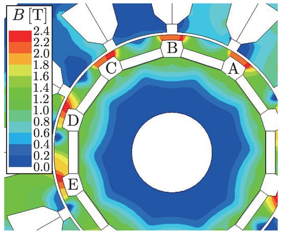
Figure 5.
Magnetic flux density distribution in the MTPA operation with an armature current of in LFBP.
3. A Saturation-Induced Variable-Flux CW Motor
Magnetic saturation is appropriately induced in stator cores to enhance variable-flux characteristics. The variable leakage-flux characteristics achieve variable-flux characteristics by passively controlling flux through magnetic circuits that consist of rotor magnets, stator windings, and cores with magnetic saturation. The variable leakage-flux characteristics in distributed winding configurations are achieved through magnetic saturation in rotor cores [9,10,11]. Therefore, variable-flux characteristics similar to the variable leakage-flux characteristics in distributed winding configurations can be achieved through magnetic saturation in stator cores. Based on the concept, a CW motor, designated as PROP, is proposed, as shown in Figure 1c, to achieve variable-flux characteristics induced by magnetic saturation. The stator core of the motor has tooth tips that are thin from the base to the end for inducing magnetic saturation. The stator slot opening is narrower than that of CONV. Hence, the width of stator tooth tips is wider than that of CONV to establish magnetic paths for the leakage flux of PMs in the stator. The stator tooth tips saturated magnetically suppresses the leakage flux of PMs and increases the d-axis flux due to PMs. The variation in the d-axis flux due to PMs can be confirmed with a conceptual magnetic circuit, as shown in Figure 6. The magnetic circuit focuses a part of the d-axis magnetic circuit that is most strongly affected by magnetic saturation. In the figure, the rotor rotates in a counterclockwise direction. Magnetic saturation shifts to the adjacent stator teeth in the clockwise direction as the rotor rotates. Therefore, similar magnetic saturation persists with the rotation of the motor.The PMs are modeled as the series-connected magnetomotive force and magnetic reluctance . The d-axis winding current produces the magnetomotive force . The magnetic reluctances of the air gap, stator core, and rotor core are denoted as , , and , respectively. In particular, the magnetic reluctance of the stator tooth tip, in which magnetic saturation appears, is expressed as . The d-axis flux due to the PMs corresponds to the flux at . The flux can be obtained from the magnetic circuit as
where . The magnetic reluctance of the stator tooth tip increases with magnetic saturation. It is confirmed that the flux increases with the magnetic reluctance by
which is the derivative of the d-axis flux due to PMs with respect to the magnetic reluctance . Therefore, the d-axis flux due to the PMs increases with magnetic saturation at the stator tooth tips. An FEM analysis is performed to determine the efficacy of PROP in this section. The dimensions of the analyzed motor are presented in Table 1. The dimensions of the stator tooth tips are determined to positively induce magnetic saturation at those locations and to achieve almost the same torque production as CONV.
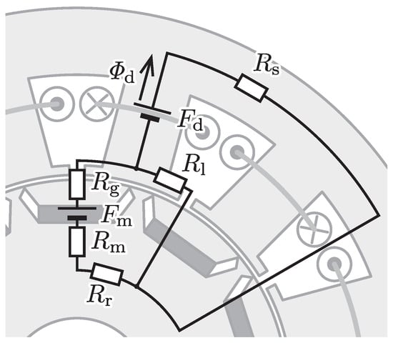
Figure 6.
Conceptual diagram of the d-axis magnetic circuit in PROP.
3.1. Magnetic Flux Density Distribution
Figure 7 shows the distribution of magnetic flux density in the MTPA operation with and in CONV and in PROP. The rotor shows a similar distribution of magnetic saturation. On the other hand, the distribution of magnetic saturation is different in the stators. In the stator of CONV, magnetic saturation rarely appears, as shown in Figure 7a. In the stator of PROP, magnetic saturation appears prominently in the bases of the stator tooth tips, as shown in Figure 7b. In particular, magnetic saturation at the stator and the rotor blocks the magnetic path in the circle of Figure 7b. The blocked magnetic path corresponds to the magnetic reluctance in the magnetic circuit shown in Figure 6. Therefore, the influence of magnetic saturation on the magnetic circuit is confirmed with the FEM analysis.
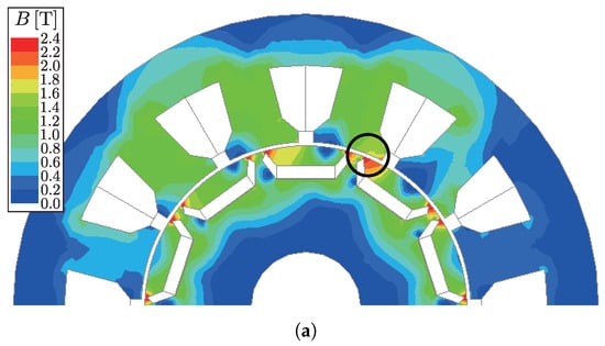
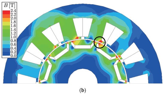
Figure 7.
Magnetic flux density distribution in the MTPA operation with an armature current of in (a) CONV and (b) PROP.
3.2. Variable-Flux Characteristics
Figure 8a shows the d-axis flux linkage for the q-axis current in PROP. Each thin line denotes the d-axis flux linkage for current phase at each armature current . The d-axis flux linkage slightly increases with the q-axis current in the zero d-axis current operation. The maximum q-axis current increases the d-axis flux linkage by approximately . The d-axis flux linkage without armature current is slightly decreased from CONV by the proposed stator. Figure 8b shows the torque for the q-axis current in PROP. The torque without magnetic saturation is estimated with (1), as shown by the dashed line. The comparison between the torques in the situations with and without magnetic saturation shows that the torque production is enhanced by magnetic saturation with a large q-axis current. The maximum q-axis current increases the torque by approximately in comparison to the situation without magnetic saturation. The motor PROP exhibits a larger enhancement in torque production through magnetic saturation with a large q-axis current than CONV and a smaller enhancement than LFBP. Therefore, the motor PROP does not exhibit the variable leakage-flux characteristics more strongly than LFBP.
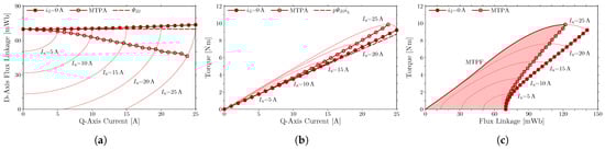
Figure 8.
Variable-flux characteristics of PROP: (a) d-axis flux linkage, (b) torque for q-axis current, and (c) torque for flux linkage.
Figure 8c shows the actual operating region, which is enclosed by the curve corresponding to the MTPA operation, the curve corresponding to the MTPF operation, and the line for zero torque at a rotational speed of . Figure 9 shows the actual operating regions in motors CONV and PROP. Here, the motor CONV is selected for the comparison because the motor CONV has an identical rotor structure with PROP and exhibits an almost identical operating region to that of LFBP, whose stack length is increased. The region of PROP is enlarged to to match the maximum torque at an armature current of . This enlargement corresponds to the increase in the stack length from to in the machine design. The actual operating region of PROP appears in the area with lower flux linkage than that of CONV. Hence, the motor PROP produces an identical torque with lower flux linkage or lower EMF than CONV. At the maximum armature current in the MTPA operation, the flux linkage decreases with the proposed stator by approximately . The proposed stator expands the operating region toward a high speed range. Therefore, the motor PROP exhibits more effective variable-flux characteristics than CONV.
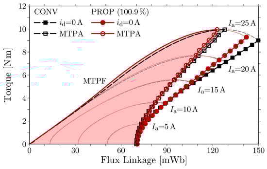
Figure 9.
Actual operating regions in the flux linkage and torque of CONV and PROP.
3.3. Motor Performances
No-load EMF is affected little by the proposed stator. Figure 10 shows the waveforms of no-load line EMF in CONV and PROP at a rotational speed of . These no-load EMFs exhibit an almost identical waveform. The fundamental amplitudes of the no-load EMFs are for CONV and for PROP. Therefore, the proposed stator affects the motor characteristics little without magnetic saturation induced by armature current.
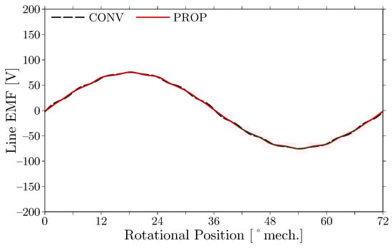
Figure 10.
No-load line EMF at a rotational speed of in CONV and PROP.
EMF is decreased by the proposed stator in the situation of magnetic saturation. Figure 11 shows the waveforms of line EMF in the MTPA operation in CONV and PROP at an armature current of and a rotational speed of . In the MTPA operation, the current phases are set at 21° in CONV and 18° in PROP. The current input causes the difference in the waveforms of the EMFs. The fundamental amplitudes of the EMFs are in CONV and in PROP. The proposed stator decreases the fundamental line EMF in the MTPA operation by approximately . This corresponds to the decrease in the flux linkage, as shown in Figure 9.
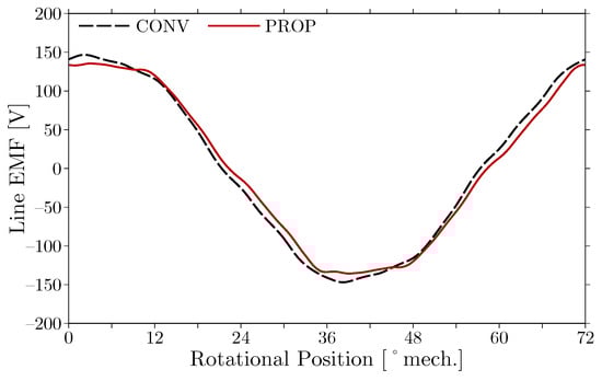
Figure 11.
Line EMF in the MTPA operation with an armature current of and a rotational speed of in CONV and PROP.
Torque production is slightly affected by the proposed stator. Figure 12 shows the waveforms of torques in the MTPA operation in CONV and PROP at an armature current of . The average torques are in CONV and in PROP. The proposed stator decreases the average torque in the MTPA operation by approximately . The torque ripple is slightly increased by the proposed stator. This is caused by the increased width of the stator tooth tips in the proposed design. Therefore, the proposed stator produces an almost identical torque in spite of the active induction of magnetic saturation.
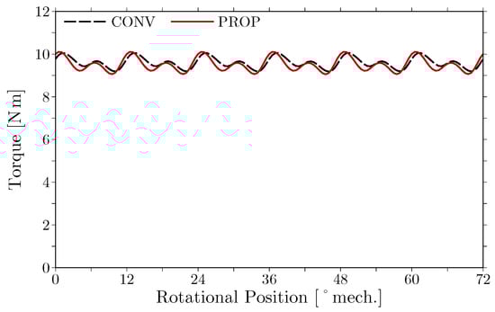
Figure 12.
Torque in the MTPA operation at an armature current of in CONV and PROP.
The operating region of the torque and speed is expanded for the constant power region by the proposed stator. Figure 13 shows the maximum torque for rotational speed or the operating region envelope of torque and speed under the conditions of a maximum armature current of and a maximum line voltage of in CONV and PROP. In the constant torque region, the torque or the operating region is decreased by approximately . In the constant power region, the proposed stator increases the torque or the operating region by more than . Therefore, the proposed stator expands the operating region by effectively inducing magnetic saturation.
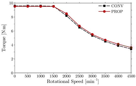
Figure 13.
Maximum torque for rotational speed under the conditions of a maximum armature current of and a maximum line voltage of in CONV and PROP.
4. Experimental Verification
The variable-flux characteristics induced by magnetic saturation in the proposed motor is verified experimentally. A prototype has been constructed for PROP, as shown in Figure 14. The dimensions are presented in Table 1. The stator coils have been wound with four conductors whose diameter is in parallel. Figure 15 shows the experimental setup. The prototype is connected with a hysteresis brake through a torque transducer. No-load EMF, static torque, and variable-flux characteristics are measured and compared with those obtained in the FEM analysis.
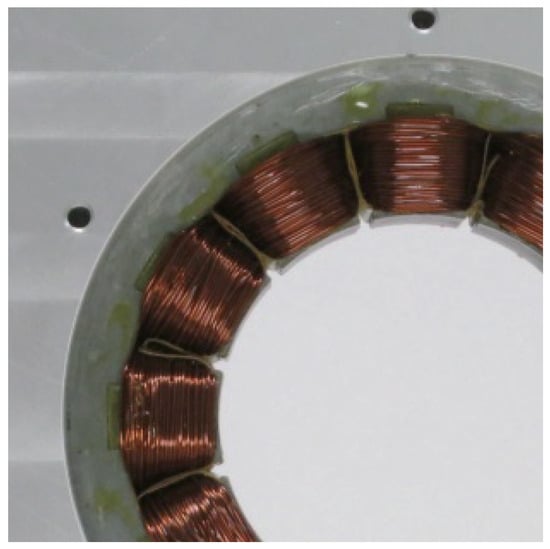
Figure 14.
Stator of the prototype.
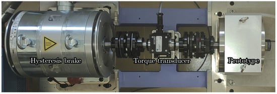
Figure 15.
Experimental setup.
Fundamental characteristics without magnetic saturation obtained with the FEM analysis is verified experimentally. No-load EMF has been measured by rotating the prototype with an induction motor at a rotational speed of . Figure 16 shows the waveform of the no-load line EMF. The waveform calculated through the FEM analysis is shown for comparison. The FEM analysis accurately predicts the actual no-load line EMF of the prototype. Static torque of the prototype has been measured at each rotor position at a q-axis current of . Figure 17 shows the measured torque with the torque calculated through the FEM analysis. The calculated torque coincides with the measured one.
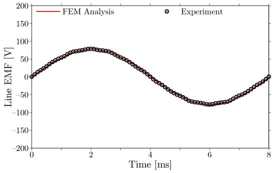
Figure 16.
No-load line EMF induced by the prototype at a rotational speed of .
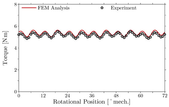
Figure 17.
Static torque produced by the prototype at a q-axis current of .
The variable-flux characteristics of the prototype are confirmed with the torque production and the induced voltage for armature current at a rotational speed of . Average torque of the prototype has been measured for armature current in the zero d-axis current operation and in the MTPA operation, as shown in Figure 18a. This figure includes the average torque calculated through the FEM analysis for comparison. In the FEM analysis, each indicated torque is obtained by subtracting a no-load torque from the corresponding electromagnetic torque because the FEM analysis cannot include the influence of the no-load torque. The no-load torque is estimated with the torque measured by rotating the prototype without armature current and the iron loss in cores and the eddy-current loss in PMs calculated through the FEM analysis at each rotational speed. The measured value of the no-load torque is at . The actual average torque can be predicted by the FEM analysis. The prototype can produce the maximum torque at the current phase predicted by the FEM analysis for each armature current. Average torque is associated with the line voltage for armature current in the zero d-axis current operation and in the MTPA operation, as shown in Figure 18b. The results calculated through the FEM analysis are shown for comparison. The line voltage is indicated as the effective or root-mean-squared value. The voltage drop across the armature winding is included in the line voltage. However, the FEM analysis cannot calculate the voltage corresponding to the iron loss in cores and the eddy-current loss in PMs. In addition, the influence of switching in an inverter for input is not included in the FEM analysis. For these reasons, the FEM analysis slightly underestimates the line voltage of the prototype. Therefore, the FEM analysis can predict the variable-flux characteristics of the prototype with a sufficient degree of accuracy.
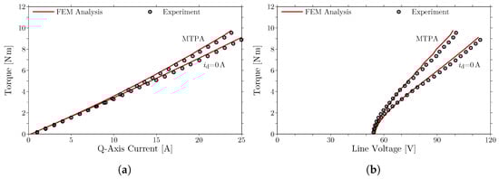
Figure 18.
Variable-flux characteristics of the prototype at a rotational speed of : (a) torque for q-axis current and (b) torque for line voltage.
The variable-flux characteristics have been verified through the comparison of the measured and calculated results for no-load EMF, static torque, and variable-flux characteristics. These results are consistent with each other. The prototype demonstrates the feasibility of the variable-flux characteristics induced by magnetic saturation. The FEM analysis validated by this comparison establishes the efficacy of the variable-flux characteristics.
5. Conclusions
A stator core design is proposed to achieve variable-flux characteristics enhanced by magnetic saturation in FSCW PM motors based on variable leakage-flux motors. The previously proposed variable leakage-flux motors with distributed winding configurations generate a dominant space harmonic or fundamental. The dominant space harmonic induces symmetrical magnetic saturation for each pole in the rotor cores. The magnetic saturation in the rotor cores contributes to the variable-flux characteristics that are effective for expanding the operating region without additional excitation systems, complicated structures, or active controls. However, magnetic saturation is not induced symmetrically for each pole in rotor cores for FSCW configurations with several dominant space harmonics. The asymmetric magnetic saturation does not contribute to effective variable-flux characteristics. For a 12-slot 10-pole configuration, the proposed stator, which has thin tooth tips for inducing magnetic saturation, achieves effective variable-flux characteristics with magnetic saturation in the stator core without additional excitation systems, complicated structures, or active controls. The proposed stator decreases the flux linkage or EMF with an identical torque and increases torque with an identical EMF. The efficacy of the proposed method has been determined numerically and experimentally. Magnetic saturation induced at suitable locations can enhance variable-flux characteristics in FSCW configurations.
Author Contributions
Conceptualization, Y.Y. and T.H.; Methodology, Y.Y.; Software, Y.Y.; Validation, Y.Y.; Formal analysis, Y.Y.; Investigation, Y.Y.; Resources, Y.Y.; Data curation, Y.Y.; Writing—original draft, Y.Y.; Writing—review & editing, Y.Y. and T.H.; Visualization, Y.Y.; Supervision, Y.Y.; Project administration, Y.Y.; Funding acquisition, Y.Y. All authors have read and agreed to the published version of the manuscript.
Funding
This research was partially supported by Nagamori Foundation Research Grant and JSPS KAKENHI Grant Number JP18K13745.
Institutional Review Board Statement
Not applicable.
Informed Consent Statement
Not applicable.
Data Availability Statement
Not applicable.
Acknowledgments
The authors would like to thank T. Yamada for fruitful discussions on the design of the prototype and Y. Murakami for assistance with the experiments. The permanent magnets of the prototype were provided by Hitachi Metals, Ltd. (Tokyo, Japan).
Conflicts of Interest
The authors declare no conflict of interest.
Abbreviations
The following abbreviations are used in this manuscript:
| CW | Concentrated winding |
| EMF | Electromotive force |
| FEM | Finite element method |
| FSCW | Fractional-slot concentrated winding |
| MTPA | Maximum torque per ampere |
| MTPF | Maximum torque per flux-linkage |
| PM | Permanent magnet |
References
- Owen, R.L.; Zhu, Z.Q.; Wang, J.B.; Stone, D.A.; Urquhart, I. Review of variable-flux permanent magnet machines. In Proceedings of the International Conference on Electrical Machines and Systems, Beijing, China, 20–23 August 2011; pp. 1–6. [Google Scholar]
- Luo, X.; Lipo, T.A. A synchronous/permanent magnet hybrid AC machine. IEEE Trans. Energy Convers. 2000, 15, 203–210. [Google Scholar]
- Fodorean, D.; Djerdir, A.; Viorel, I.A.; Miraoui, A. A double excited synchronous machine for direct drive application—design and prototype tests. IEEE Trans. Energy Convers. 2007, 22, 656–665. [Google Scholar] [CrossRef]
- Ostovic, V. Memory motors—A new class of controllable flux PM machines for a true wide speed operation. In Proceedings of the IEEE Industry Applications Society Annual Meeting, Chicago, IL, USA, 30 September–4 October 2001; Volume 4, pp. 2577–2584. [Google Scholar]
- Ostovic, V. Memory motors. IEEE Ind. Appl. Mag. 2003, 9, 52–61. [Google Scholar] [CrossRef]
- Oga, S.; Ishii, T.; Nonaka, T.; Ohto, M. Manufacturing and testing the prototype of variable magnetic flux motor. In Proceedings of the IEE-Japan Industry Applications Society Conference, Yamaguchi, Japan, 17–18 August 2013; Volume 3–32, pp. 201–206. (In Japanese). [Google Scholar]
- Nonaka, T.; Oga, S.; Ohto, M. Consideration about the drive of variable magnetic flux motor. IEEJ Trans. Ind. Appl. 2015, 135, 451–456. (In Japanese) [Google Scholar] [CrossRef]
- Ishii, T.; Nonaka, T.; Oga, S.; Ohto, M. Manufacturing and control of a variable magnetic flux motor prototype with a mechanical adjustment method. IEEJ Trans. Ind. Appl. 2016, 136, 328–335. (In Japanese) [Google Scholar] [CrossRef]
- Limsuwan, N.; Kato, T.; Akatsu, K.; Lorenz, R.D. Design and evaluation of a variable-flux flux-intensifying interior permanent-magnet machine. IEEE Trans. Ind. Appl. 2014, 50, 1015–1024. [Google Scholar] [CrossRef]
- Kato, T.; Minowa, M.; Hijikata, H.; Akatsu, K.; Lorenz, R.D. Design methodology for variable leakage flux IPM for automobile traction drives. IEEE Trans. Ind. Appl. 2015, 51, 3811–3821. [Google Scholar] [CrossRef]
- Hijikata, H.; Akatsu, K.; Kato, T. Experimental studies of variable leakage flux type IPMSM. IEEJ Trans. Ind. Appl. 2017, 137, 737–743. (In Japanese) [Google Scholar] [CrossRef]
- Cros, J.; Viarouge, P. Synthesis of high performance PM motors with concentrated windings. IEEE Trans. Energy Convers. 2002, 17, 248–253. [Google Scholar] [CrossRef]
- Magnussen, F.; Sadarangani, C. Winding factors and Joule losses of permanent magnet machines with concentrated windings. In Proceedings of the International Electric Machines and Drives Conference, Madison, WI, USA, 1–4 June 2003; Volume 1, pp. 333–339. [Google Scholar]
- Libert, F.; Soulard, J. Investigation on pole-slot combinations for permanent-magnet machines with concentrated windings. In Proceedings of the International Conference on Electrical Machines, Cracow, Poland, 5–8 September 2004; pp. 530–535. [Google Scholar]
- Bianchi, N.; Pré, M.D. Use of the star of slots in designing fractional-slot single-layer synchronous motors. IEE Proc.-Electr. Power Appl. 2006, 153, 459–466. [Google Scholar] [CrossRef]
- Bianchi, N.; Bolognani, S.; Pré, M.D.; Grezzani, G. Design considerations for fractional-slot winding configurations of synchronous machines. IEEE Trans. Ind. Appl. 2006, 42, 997–1006. [Google Scholar] [CrossRef]
- EL-Refaie, A.M.; Shah, M.R.; Qu, R.; Kern, J.M. Effect of number of phases on losses in conducting sleeves of surface PM machine rotors equipped with fractional-slot concentrated windings. IEEE Trans. Ind. Appl. 2008, 44, 1522–1532. [Google Scholar] [CrossRef]
- EL-Refaie, A.M. Fractional-slot concentrated windings synchronous permanent magnet machines: Opportunities and challenges. IEEE Trans. Ind. Electr. 2010, 57, 107–121. [Google Scholar] [CrossRef]
- Yokoi, Y.; Higuchi, T.; Miyamoto, Y. General formulation of winding factor for fractional-slot concentrated winding design. IET Electr. Power Appl. 2016, 10, 231–239. [Google Scholar] [CrossRef]
- Ishak, D.; Zhu, Z.Q.; Howe, D. Eddy-current loss in the rotor magnets of permanent-magnet brushless machines having a fractional number of slots per pole. IEEE Trans. Magn. 2005, 41, 2462–2469. [Google Scholar] [CrossRef]
- Bianchi, N.; Fornasiero, E. Index of rotor losses in three-phase fractional-slot permanent magnet machines. IET Electr. Power Appl. 2009, 3, 381–388. [Google Scholar] [CrossRef]
- Bianchi, N.; Bolognani, S.; Fornasiero, E. An overview of rotor losses determination in three-phase fractional-slot PM machines. IEEE Trans. Ind. Appl. 2010, 46, 2338–2345. [Google Scholar] [CrossRef]
- Li, J.; Choi, D.W.; Son, D.H.; Cho, Y.H. Effects of MMF harmonics on rotor eddy-current losses for inner-rotor fractional-slot axial flux permanent magnet synchronous machines. IEEE Trans. Magn. 2012, 48, 839–842. [Google Scholar] [CrossRef]
- Fornasiero, E.; Bianchi, N.; Bolognani, S. Slot harmonic impact on rotor losses in fractional-slot permanent-magnet machines. IEEE Trans. Ind. Electr. 2012, 59, 2557–2564. [Google Scholar] [CrossRef]
- Morimoto, S.; Tong, Y.; Takeda, Y.; Hirasa, T. Loss minimization control of permanent magnet synchronous motor drives. IEEE Trans. Ind. Electr. 1994, 41, 511–517. [Google Scholar] [CrossRef]
Disclaimer/Publisher’s Note: The statements, opinions and data contained in all publications are solely those of the individual author(s) and contributor(s) and not of MDPI and/or the editor(s). MDPI and/or the editor(s) disclaim responsibility for any injury to people or property resulting from any ideas, methods, instructions or products referred to in the content. |
© 2023 by the authors. Licensee MDPI, Basel, Switzerland. This article is an open access article distributed under the terms and conditions of the Creative Commons Attribution (CC BY) license (https://creativecommons.org/licenses/by/4.0/).