Article

Technology Modules Providing Solutions for Agile Manufacturing

by
Miha Deniša
1,*,
Aleš Ude
1,
Mihael Simonič
1,
Tero Kaarlela
2,
Tomi Pitkäaho
2,
Sakari Pieskä
2,
Janis Arents
3,
Janis Judvaitis
3,
Kaspars Ozols
3,
Levente Raj
4,
András Czmerk
4,
Morteza Dianatfar
5,
Jyrki Latokartano
5,
Patrick Alexander Schmidt
6,
Anton Mauersberger
6,
Adrian Singer
6,
Halldor Arnarson
7,
Beibei Shu
7,
Dimosthenis Dimosthenopoulos
8,
Panagiotis Karagiannis
8,
Teemu-Pekka Ahonen
9,
Veikko Valjus
9 and
Minna Lanz
5
add Show full author list remove Hide full author list
1
Humanoid and Cognitive Robotics Laboratory, Department of Automatics, Biocybernetics, and Robotics, Jožef Stefan Institute, 1000 Ljubljana, Slovenia
2
Department of Industrial Management, Centria University of Applied Sciences, 84100 Ylivieska, Finland
3
Institute of Electronics and Computer Science, LV-1006 Riga, Latvia
4
Department of Mechatronics, Optics and Mechanical Engineering Informatics, Faculty of Mechanical Engineering, Budapest University of Technology and Economics, H-1111 Budapest, Hungary
5
Faculty of Engineering and Natural Sciences, Tampere University, 33100 Tampere, Finland
6
Fraunhofer IWU, 09126 Chemnitz, Germany
7
Department of Industrial Engineering, Faculty of Engineering Science and Technology, UiT The Arctic University of Norway Campus Narvik, 8514 Narvik, Norway
8
Laboratory for Manufacturing Systems and Automation, Department of Mechanical Engineering and Aeronautics, University of Patras, 26504 Patras, Greece
9
Fastems Oy Ab, 33840 Tampere, Finland
*
Author to whom correspondence should be addressed.
Machines 2023, 11(9), 877; https://doi.org/10.3390/machines11090877
Submission received: 30 June 2023 / Revised: 25 August 2023 / Accepted: 26 August 2023 / Published: 1 September 2023
(This article belongs to the Section Advanced Manufacturing)

Abstract

:
In this paper, we address the most pressing challenges faced by the manufacturing sector, particularly the manufacturing of small and medium-sized enterprises (SMEs), where the transition towards high-mix low-volume production and the availability of cost-effective solutions are crucial. To overcome these challenges, this paper presents 14 innovative solutions that can be utilized to support the introduction of agile manufacturing processes in SMEs. These solutions encompass a wide range of key technologies, including reconfigurable fixtures, low-cost automation for printed circuit board (PCB) assembly, computer-vision-based control, wireless sensor networks (WSNs) simulations, predictive maintenance based on Internet of Things (IoT), virtualization for operator training, intuitive robot programming using virtual reality (VR), autonomous trajectory generation, programming by demonstration for force-based tasks, on-line task allocation in human–robot collaboration (HRC), projector-based graphical user interface (GUI) for HRC, human safety in collaborative work cells, and integration of automated ground vehicles for intralogistics. All of these solutions were designed with the purpose of increasing agility in the manufacturing sector. They are designed to enable flexible and modular manufacturing systems that are easy to integrate and use while remaining cost-effective for SMEs. As such, they have a high potential to be implemented in the manufacturing industry. They can be used as standalone modules or combined to solve a more complicated task, and contribute to enhancing the agility, efficiency, and competitiveness of manufacturing companies. With their application tested in industrially relevant environments, the proposed solutions strive to ensure practical implementation and real-world impact. While this paper presents these solutions and gives an overview of their methodologies and evaluations, it does not go into their details. It provides summaries of comprehensive and multifaceted solutions to tackle the evolving needs and demands of the manufacturing sector, empowering SMEs to thrive in a dynamic and competitive market landscape.

1. Introduction

To avoid the relocation of manufacturing plants to countries with low wages and lower production costs, the manufacturing sector needs to transition beyond the standard automation approaches. Changes in market demands and optimizations of supply chains also call for new paradigms in manufacturing processes. Moreover, the current trends are pushing the manufacturing sector towards high-mix low-volume production, which calls for collaborative and more flexible solutions and production systems. As a high percentage of manufacturing companies (approx. 80% in the EU) are small and medium-sized enterprises (SMEs), new paradigms must support the introduction of new production processes beyond those currently used in large manufacturing companies. In order to stay competitive and maintain efficiency, new manufacturing solutions for SMEs need to be low-cost and easy to integrate. The solutions presented in this paper fulfill these objectives and all strive towards one goal: increasing the robot-supported agile production. They implement methods that showed promise in laboratory settings but have not yet become standard in the manufacturing industry. While not all presented solutions have novel underlying methodologies, they strive towards industrial implementation through modularization, low cost, and industry-relevant evaluations and improvements. By designing the solutions as stand-alone, easy-to-integrate, and well-defined modules, they can be integrated as individual solutions or combined to solve a more complex task in industrially relevant environments, i.e., technology readiness level (TRL) 5 and above. The 14 presented solutions bring together different key novel robot technologies from various fields: from robot cell development to human–robot collaboration.
A significant part of the robot work cell development, especially in the automotive industry, is dedicated to ensuring a firm placement of workpieces. In manufacturing systems, fixturing jigs are usually used to firmly hold workpieces so that a robot can perform its operations reliably. As the variability of workpieces is increasing and the batches are becoming smaller [1], agile manufacturing must also address the construction and maintenance of fixturing systems. A vast majority of fixturing systems in industry are specifically designed and constructed for each workpiece. As an alternative to dedicated fixtures, reconfigurable fixtures can be used. They adapt to different workpieces either by internal actuators or external manipulation [2,3]. While reconfigurable fixtures have already been utilized by industry, mainly hand-adjustable tables are used for reconfiguration [4]. One of our presented solutions, “Optimal locations and postures of reconfigurable fixtures”, tackles passive fixturing systems that can be reconfigured by robots and enables the determination of optimal placement and configurations of a fixturing system for multiple workpieces. The proposed solution significantly reduces the cost of introducing reconfigurable fixturing systems into manufacturing processes.
The most essential component in the electronics sector is the printed circuit boards (PCBs). There are two primary types of PCBs, through-hole technology (THT) and surface mount device (SMD) PCBs [5]. THT PCBs have been used for decades as they are preferred for their durability, reliability, and ease of repair [6]. Automated assembly of THT PCBs has been a challenge for the electronics industry due to the manual labor required, leading to longer production times and increased errors. While there are automated solutions available, they are mostly used for SMD components. Automation for THT components needs extra steps in aligning the connection wires [7]. Thus, the automation is costly, limiting its accessibility to smaller manufacturers. Consequently, there is a growing concern about developing a low-cost automation solution for THT PCB assembly. In this paper, we present a low-cost automation solution that combines a high-precision robot with a vision system. It has the potential to improve the efficiency and accuracy of THT PCB assembly, making it an ideal option for small-scale production or manufacturers with varying order sizes. By integrating a robot and vision system, we have developed an affordable and accurate solution to address the challenges of manual THT PCB assembly.
Computer vision is a useful component for novel solutions in robot cell design. The next presented solution focuses on object detection, or, more precisely, on the data collection methods for object detection. Data collection and processing play an important role in machine-learning processes where on average, more than 80% of time is spent on the collection and processing of data [8]. Data-driven machine learning methods are important for robotics because they enable robots to anticipate events and prepare for them in advance, thus coping with dynamic conditions and unforeseen situations.Data collection techniques vary depending on the use case [9]. In the field of smart manufacturing, where product variety is large and precision should not be lost when the system is reconfigured for a new product, the re-usability of existing data sets is limited. Manual labeling methods are time-consuming, expensive, require expert knowledge, and can lead to human errors [10]. With the provided solution, synthetic data generation is used, which reduces the burden of manual labeling and data gathering in the manufacturing process.
Besides collecting training data for vision-based control, simulation can also be utilized to assess wireless sensor networks for Industrial Internet of Things (IIoT) in a 3D environment. Wireless sensor networks (WSNs) are networks of small, low-cost, low-power devices that communicate wirelessly to perform a specific task. They consist of nodes equipped with sensors that measure physical or environmental parameters, which communicate with each other to collect, process, and transmit data wirelessly. WSNs have a wide range of applications, including industrial control, environmental monitoring, healthcare, and home automation [11]. They are used when wired connections are not feasible or too expensive, such as in remote or hard-to-reach areas. The presented solution provides a WSN simulation in a virtual IIoT infrastructure in order to test the cybersecurity, and optimize the position of IIoT devices and orientations of the antennas.
While simulation can benefit assessing wireless sensor networks for IIoT, innovative IoT-based predictive maintenance can improve productivity, product quality, and overall effectiveness. This can be achieved by using the actual operating condition of the equipment to optimize the plant operation [12]. This implies relying on the data gathered from the plant about mechanical conditions, system efficiency, and other indicators to determine the actual time-to-failure instead of using average-life statistics. Zonta et al. [13] reason that the dissemination of IoT together with predictive maintenance-related research in Industry 4.0 is growing, yet the review of the actual sensor network deployments shows that from all the actually deployed sensor networks targeting the industry, only approximately one third are in the usable Technology Readiness Level of TRL 7 or higher. This suggests that there is a possible improvement for innovative IoT-based predictive maintenance solutions and their development. We provide a solution that enables both the initial predictive maintenance deployment as well as the possibility to improve and expand on the used techniques by using the “Infrastructure as a Service” approach.
An advanced simulation environment is also the core of another solution presented in this paper, “Virtualization of a robot cell for training and production prototyping”, which uses simulation for operator training. The increased requirements for system agility also set new requirements for operator understanding and planning. Currently, the training of the operators takes place on-premise with the associated production equipment, through the user interface of the system. This means that the production equipment is offline during the training and familiarization period resulting in a need to balance between operator training and reduced production capacity [14]. The proposed solution focuses on the control of a simulated manufacturing hardware using a real controller. The simulated hardware is represented in a real-time 3D-environment, which can be used for demonstrating actual system functionality, training employees, virtual commissioning, and for testing production operations for new parts.
As we have already mentioned, industrial production is currently undergoing a shift towards customization and personalized production, which requires a more frequent reconfiguration of manufacturing systems. This requires not only the development of new reconfigurable hardware for robotic cells but also new methods for the programming of robots. One of the solutions proposed to ease the task for robot programming by inexperienced workers is based on a virtual reality (VR) environment, which uses digital twin technologies and IIoT to provide an intuitive and safe method for programming robots.
Robot programming using a teach pendant can be cumbersome and even hazardous when the intended workpiece is a physically large object. Programming performed offline in a simulation or VR environment solves some issues of manual programming, but it requires a digital model of the environment, which can sometimes be difficult to obtain. By generating robot trajectories autonomously, i.e., “on-the-fly” by using inputs from a 3D scanner, we can avoid manual programming without using digital models. In the proposed solution, the digital shadow of the robot [15] is supplemented by a digital shadow of the workpiece during the process of scanning large objects.
Force-based tasks are another type of task where it is problematic to use digital models as it is often not possible to accurately simulate forces. We have therefore developed a new methodology for robot programming by demonstration where the programmer manually guides the robot through the desired tasks instead of coding. In the past, considerable effort has been dedicated to the automation of tasks such as polishing and grinding using industrial robots [16]. Methods based on a predefined skills library have also been proposed [17]. The solution proposed in this paper can be used to program force-based skills from scratch. It is based on the concept of virtual mechanisms and can replicate the forces and torques arising during the task demonstration by a human expert. The proposed approach was validated in a relevant environment (TRL 5) in collaboration with an industrial partner.
Human–robot collaboration is gaining ground in the manufacturing industry, not only as a way to ease the programming of robots but also to optimize task allocation and workflow management. As modern production systems incorporate human operators and robots [18], novel solutions are addressing the scheduling of tasks between human–robot collaborative teams [19,20]. However, these approaches lack online reconfiguration of task plans during task execution, limiting them to offline planning. The solution presented in this paper introduces a comprehensive framework that efficiently distributes work between humans and robots, adapts to changes (e.g., malfunctions) during production, and enables online workload reconfiguration.
When human–robot collaborative teams operate simultaneously in a shared workspace, humans have limited possibilities to follow static user interfaces or to use physical buttons [21]. In the case of complex and demanding assembly tasks, the operator must focus both on the actual task as well as the activities of the robot supporting the operator. Our solution for more effective human–robot collaboration uses a standard digital light processing (DLP) projector to present the operator with a graphical user interface (GUI) projected on the robot working area. Besides collaborative task instructions, the system also presents safety information to the operator.
As human–robot collaboration is being introduced to manufacturing halls, human safety is paramount. Two solutions presented in this paper focus on increasing human safety in a shared workspace. “Safe human detection in a collaborative work cell” is an open-source approach to safety in a flexible production cell. It utilizes sensor fusion of multiple, safety-certified monitoring devices. An additional indoor location system and a 360-degree camera enhance safety by tracking the movements of human workers and mobile robots. The proposed solution combines devices and approaches that have already been used by industry. For virtual safety training and risk assessment, a digital twin of the production cell is used. The second human safety module is not focused on human detection but rather deals with adaptive speed and separation monitoring. A multi-level distinction based on sharing physical workspace and sharing tasks with cognitive engagement [22] has been proposed. The first level involves sharing the workspace without contact or coordination, while the second level involves direct interaction through gestures, vocal instructions, and force application. This approach has been proposed in various use cases [23,24] where safety is addressed through mechanical, sensory, and control safety mechanisms.
While human–robot collaboration can increase the agility of the manufacturing process, so can a wider implementation of automated ground vehicles (AGVs). The last solution presented in this paper incorporates an AGV and other emerging technologies in the intralogistics domain. We have provided a module for optical line following and visual servoing of an omnidirectional mobile robot. Such functionalities are often required by manufacturing SMEs that need robots for smart assembly solutions.

2. Solutions for Agile Manufacturing

Fourteen various solutions designed as stand-alone easy-to-implement modules covering eleven different topics are presented in this section. Each solution aims to increase agility in the manufacturing sector by pushing beyond standard approaches or implementing ones being on the cusp of industrial implementation. Various stages of the manufacturing process are tackled in areas of robot cell development, computer vision, simulation, IoT, robot programming, VR, digital twins, human-robot collaboration, safety, and AGVs.

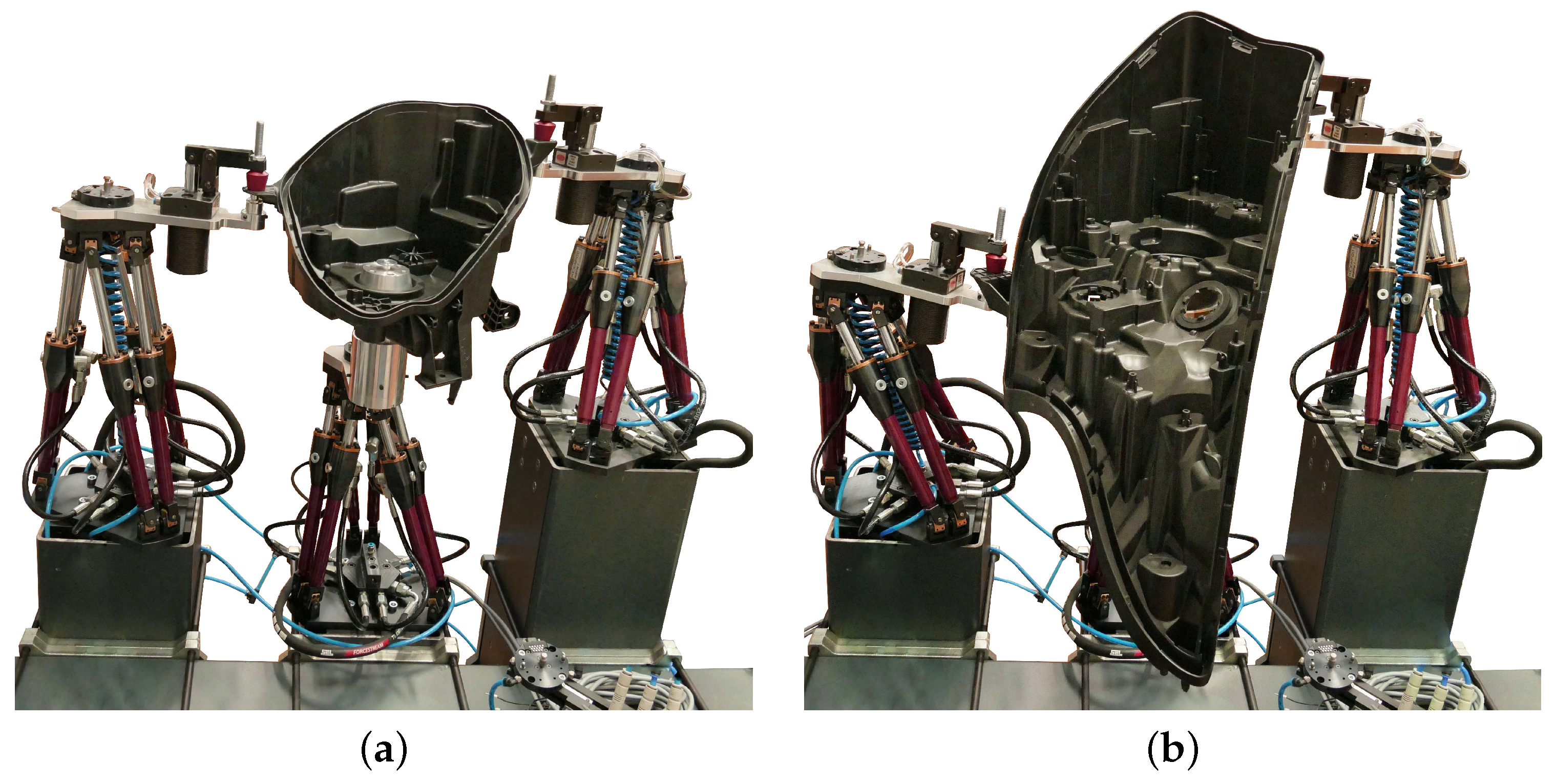
2.1. Optimal Locations and Postures of Reconfigurable Fixtures

The design of fixtures plays an important role in the area of robot cell development, as manufacturing production lines often call for firmly fixed workpieces in order to ensure reliable robot operations and proper tolerances. While traditional fixtures are specially designed and constructed for each workpiece, (passive) reconfigurable fixtures provide a more agile and affordable solution. Parallel mechanisms, e.g., Stewart platforms, are ideal components of fixturing systems as they excel in load-bearing properties while providing 6 degrees of freedom for fixturing points. Fixturing systems used in this module are based on Stewart platforms, which we call hexapods. They are passive, i.e., they have no actuators.
While the hexapod’s base is firmly mounted in the cell, the top plate can be moved once the brakes are released. The robot is used to move the top plates and thus reposition the fixture points. When deploying multiple hexapods to mount a set of different workpieces, it is necessary to determine optimal base locations and top plate postures. Determining such a layout can be a tedious and time-consuming task, which becomes especially difficult where multiple workpieces with multiple anchor points need to be firmly positioned in the work cell [25]. An example fixturing system with three hexapods holding two different workpieces can be seen in Figure 1.
This module provides an optimization procedure for the determination of an optimal layout of a fixturing system consisting of M hexapods for N different workpieces. For this purpose, we defined a nonlinear constrained optimization problem. By solving this optimization problem, we obtain the mounting locations of the hexapods in the cell b as well as the postures of the top plates p so that all N workpieces can be placed onto the fixturing system without re-positioning their bases. The computed postures of the top plates can then be established by a robot, which moves the platforms’ top plates without any human intervention.
To formulate an optimization problem, a suitable criterion function and constraints need to be defined. We define the criterion function as
c ( b i , p i ) = j = 1 N Δ w j + j = 1 N i = 1 M Δ p i , j ,
where Δ w j is the pose difference of the workpiece j with respect to its preferred pose and Δ p i , j the pose difference between the top plate of hexapod i and its natural pose. This criterion function thus prefers workpiece poses close to the ideal workpiece poses specified by the production process expert and hexapod postures that are close to the neutral posture of the hexapod. By preferring top plate poses close to their natural posture, we ensure that hexapods are as far as possible from their kinematic limits. To make certain that all workpieces can be mounted on the hexapods, we define a set of constraints. Every workpiece is attached to the top plates of all hexapods in the fixturing system at predefined anchor points. Thus, the locations and postures of all hexapods in a fixturing system must fulfill the constraint that the desired anchor points lie within the workspace of the hexapods. We also introduce additional constraints so that the base plates of the hexapods do not overlap. Finally, to prevent collisions between the legs of hexapods, which could occur if top plates rotate too much, the limits on the top plate orientations are set.
Additional constraints can be added to further define the desired solution.
An industrial use case study showed that the proposed optimization system can be used to compute the fixturing system layouts that enable the mounting of different automotive light housings (see Figure 1). To evaluate the proposed procedure more in depth, a modular workpiece with a different number of anchor points, thus requiring different numbers of hexapods for mounting, was designed in simulation. Computational times for different numbers of workpieces and different numbers of hexapods in the fixturing system were then studied. As expected, the computational time increases with the number of workpieces and hexapods included in the layout: from under 5 s for 3 hexapods and up to 40 s for a solution including 6 hexapods and 6 different workpieces.
The module described above provides the calculation of optimal layouts for reconfigurable fixturing systems that can hold multiple workpieces. The fixturing systems built from hexapods and the procedure for optimal layout calculation were evaluated in a practical industrial scenario and thus achieved TRL 6. The proposed solution is flexible and enables the consideration of different production aspects by adding constraints based on the current production demands.

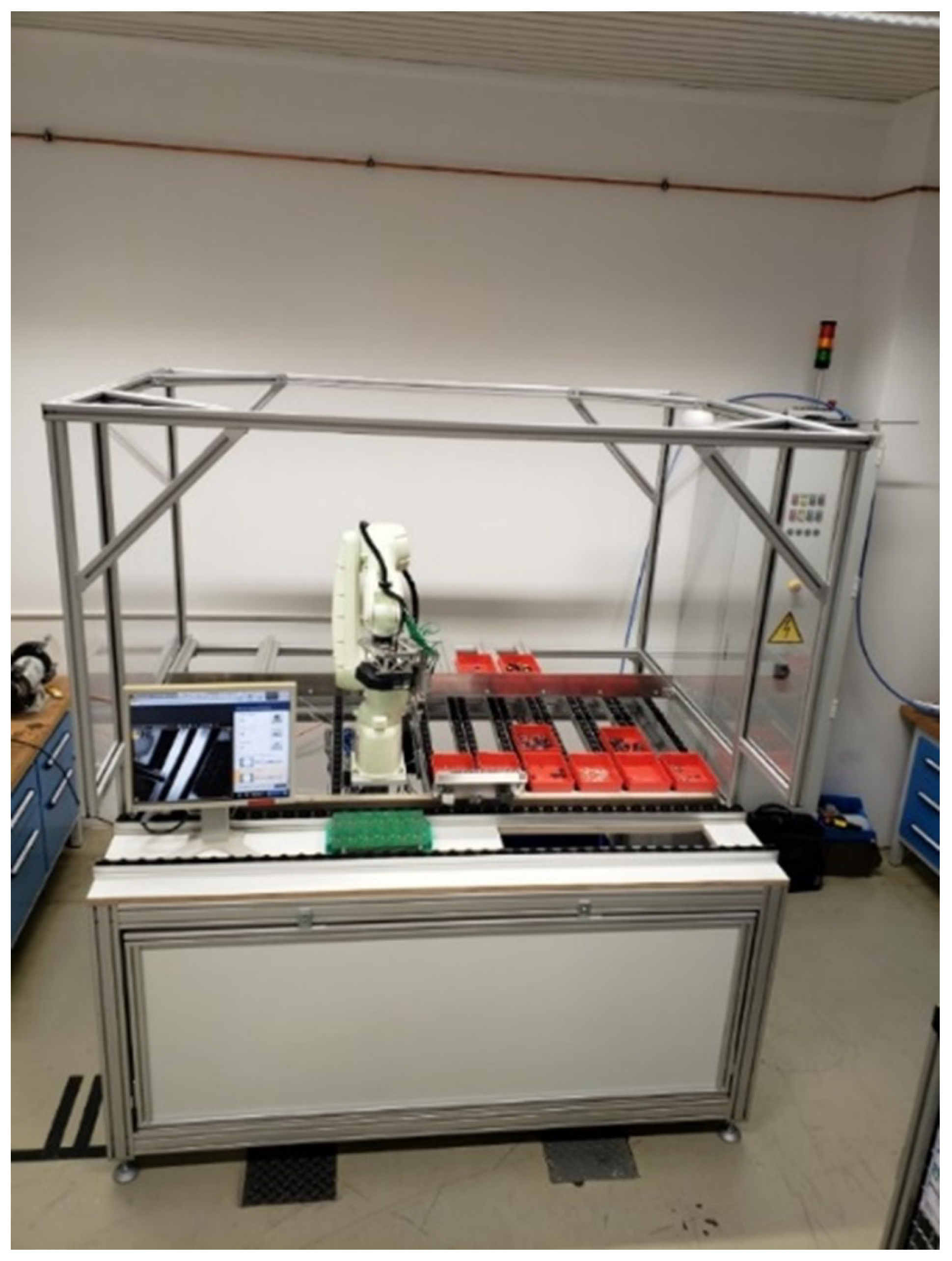
2.2. Assembly of Through-Hole Technology Printed Circuit Boards

Another robot cell development solution tackles the assembly of through-hole technology printed circuit boards (THT-PCBs), which is a common practice in the electronics industry. While there are possible solutions for fully automated assembly, they are often expensive and may not be cost-effective for smaller manufacturers. The assembly is thus typically performed manually, which can be time-consuming and error-prone [26]. Our solution uses a low-cost robot with high precision, combined with a vision system, to automatically assemble electronic components on THT-PCBs. The vision system allows the robot to locate the components in their containers and place them accurately in the corresponding positions on the THT-PCBs. A pre-existing software is used to recognize the components based on their contours and locate them accurately in their containers. The robot is programmed to pick up the components from their containers and place them in the corresponding positions on the THT-PCBs. A seamless integration of the robot, vision system, and software is ensured to achieve precise and efficient assembly.
The evaluation of the proposed solution was performed with various components and showed that the robot was able to pick up and place the components accurately on the THT-PCBs. The assembly station used for evaluation in a laboratory setting can be seen in Figure 2. The vision system was also able to locate the components in their containers correctly, ensuring precise placement on the THT-PCBs. The proposed assembly of THT-PCBs was further evaluated through three Key Performance Indicators (KPIs) to provide a comprehensive overview of the system’s capabilities, costs, and efficiency in comparison to traditional manual assembly methods. By evaluating the programming effort for the assembly set-up, we saw 2 months (318 h) for the full set-up, including all stages of programming and testing. Adding a new component post initial set-up requires a week (39 h) for reliable assembly. To provide a potential cost insight to users, we estimated the total hardware cost of the demonstrator at 60,000 €. To gauge the system’s potential, we compared robot assembly times to humans. Measurements focused on the first workstation components. Methods-time-measurement (MTM) was used to determine human worker times. Comparatively, the robot took 123 s for a single PCB’s components. Thus, it needs 434.12% of the time a human worker would take. Conversely, human workers take only 23% of the robot’s time. The evaluations showed that partial automation promises future benefits, including continuous work without breaks and operations outside regular shifts. Indirect benefits include potential automation of production line documentation and better integration into digital processes. Additionally, positive ergonomic impacts might enhance worker satisfaction and reduce absenteeism [27].

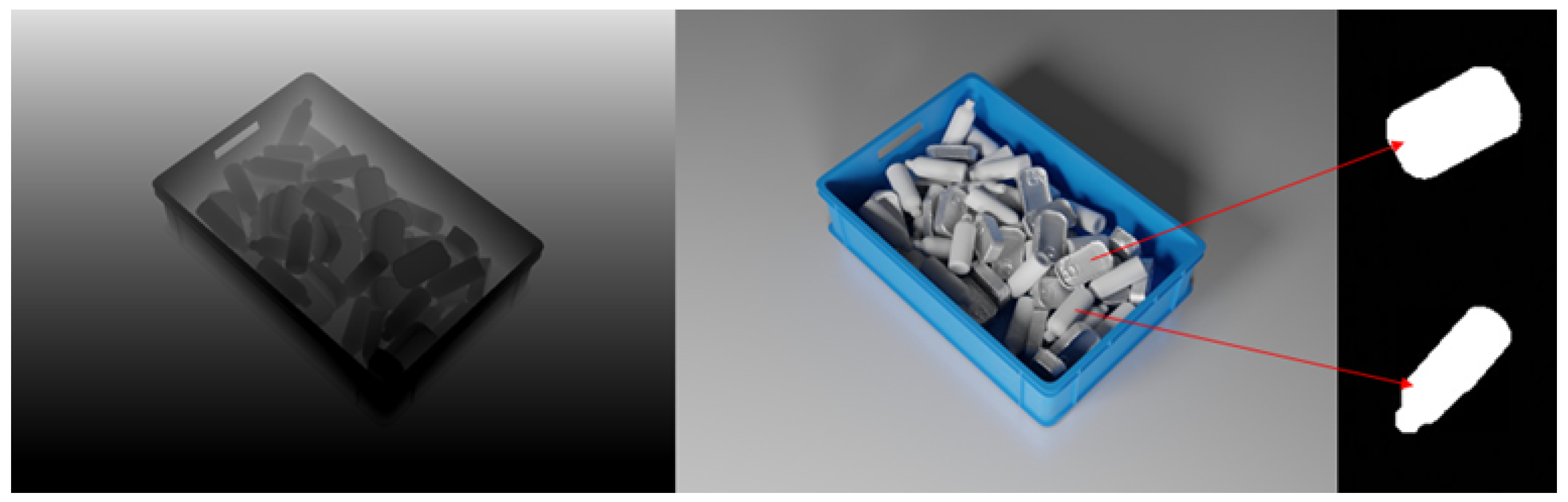
2.3. Object Detection

While standard off-the-shelf vision solutions offer benefits in automating assembly processes, exploring novel approaches in computer vision and simulation can bring further advantages to the manufacturing sector, enhancing its agility. This solution introduces a novel data preparation method that employs a simulation environment for a bin-picking scenario. In object detection tasks, manual labeling involves marking each object with a bounding box, while for segmentation, each pixel belonging to the object needs to be marked. Dynamic environments, particularly those with randomly piled objects, pose challenges due to uncertainties and varying environmental conditions. To meet precision requirements in a smart manufacturing environment, the training data set ideally should cover these diverse conditions. However, acquiring and labeling real data can be time-consuming and resource-intensive, especially when attempting to recreate all possible configurations.
To address these challenges and facilitate the application of modern computer vision methods in industry, the proposed solution centers around synthetic data generation. By employing a systematic rendering process that adjusts various image parameters, such as object, camera, and light positions, object color or texture, surface properties, brightness, contrast, and saturation, the approach produces highly realistic synthetic images that mimic the characteristics of real data. This synthetic data generation results in a diverse data set with varying levels of resolution and realism, tailored to specific requirements.
An essential advantage of the synthetic data generation approach is the automatic generation of labels and masks for the generated data (as shown in Figure 3), significantly reducing the manual effort needed for data gathering and labeling. This streamlining of the process makes it easier and more efficient to utilize state-of-the-art computer vision techniques in practical industrial applications.
The method presented allows for almost fully automated data generation, with only minimal manual adjustments required on a per-use-case basis. The reduction in manual effort compared to traditional data labeling is substantial. For the object detection task, the manual labeling of 2200 scenes took around 80 h, while the synthetic data generation process required only about 30 min, resulting in an impressive manual process reduction of approximately 99%.
However, despite the advantages of data generation in simplifying system reconfiguration, there are potential trade-offs in precision results due to differences between simulated and real-world data. To comprehensively assess the performance of the synthetic data generation approach, a series of experiments were conducted, and detailed results can be found in [28]. The study employed combinations of the generated data set, real data set, and various mixtures of both to train an object detector, which was subsequently evaluated on two distinct test data sets. In most cases, models trained with a higher ratio of real data outperformed those trained primarily on synthetic data in terms of precision. Nevertheless, even the models trained exclusively on synthetic images demonstrated sufficient precision for identifying suitable grasping candidates in the bin-picking scenario. Introducing synthetic images to diversify the training data set led to an increase in precision; however, surpassing a synthetic data ratio of 50% resulted in diminished precision.
Overall, the synthetic data generation framework integrated into the object detection module shows promising results for computer-vision-based robot control and serves as a valuable complement to real data, particularly when the available variation in real training data is limited. It is essential to find the optimal balance of real and synthetic data to achieve peak precision since an excessive reliance on synthetic images may lead to reduced accuracy. Emphasizing the data preparation process, which has reached TRL 6, the framework for data generation can be effectively utilized in various computer-vision-based robotic grasping tasks. Nonetheless, further developments are required to establish a comprehensive grasping pipeline tailored to the specific application scenario.

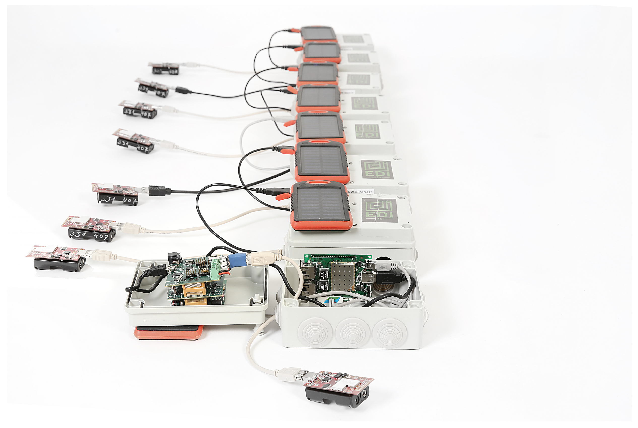
2.4. Industrial IoT Robustness Simulation Modules

More and more sensors are needed to monitor industrial processes and to continuously collect measurement data from industrial plants and devices, enabled and driven primarily by IoT [29]. As a basis for data exchange, WSNs are networks of small, low-cost devices with low power consumption that communicate wirelessly with each other to perform a specific task. They consist of nodes equipped with sensors that measure physical or environmental parameters, which communicate with each other to collect, process, and transmit data wirelessly. WSNs have a wide range of applications, including environmental monitoring, industrial control, healthcare, and home automation [11]. They are used when wired connections are not feasible or too expensive, such as in remote or hard-to-reach areas. The state-of-the-art for WSNs includes low-power wide-area networks (LPWANs), energy harvesting, edge computing, machine learning, and security techniques [30].
The Industrial IoT Robustness Simulation provides an extensible and highly configurable “discrete event simulator”. The current implementation of different simulation models realizes a simulation for wireless sensor networks in a 3D environment. The two modules that are the focus of this solution are “Network Device Positioning” and “Cyber-security Fallback Simulation”. Both new software artifacts extend the core functionality of a software project called d3vs1m-discrete events & development for network device simulation. The d3vs1m project is an open source library and simulation tool for simulating wireless sensor networks to support the integration process of such IIoT networks in the manufacturing environment. Due to the processes and logistical challenges, there are many mobile and stationary operating resources in production, such as mobile robots, edge devices, or automated guided vehicles (AGVs), that have to communicate in networks with each other. Such networks are vulnerable to physical changes in the environment and cyber attacks. This use-case simulates the behavior of WSNs in a virtual IIoT infrastructure. Today’s challenges need to be addressed in simulations; current limitations include the complexity of simulating large networks, the difficulty of accurately modeling real-world user behavior and network conditions, and the computational resources required to perform simulations. In addition, there may be issues with standardization and compatibility between different simulation tools and frameworks. Most importantly, access to open source products for the wireless networking domain is severely limited. During the simulation, the distances, the received signal strengths, and the relative orientation between the radio antennas are calculated as network characteristics. Within the d3vs1m simulation, the position of each device can be changed by the device simulation, so that mobile devices or moving parts can be simulated correctly. Changing the position leads to a recalculation of the relationships between all network participants. In addition, a new technology called Network and Intrusion Detection System (IDS) has been implemented, this provides fallback simulation and can be seen as an extension of the simulation core, specifically for mobile networks. The module provides a taxonomy of more than 45 cyber attacks for different types of networks or physical layers. The reference implementation focuses on battery-powered systems and implements a battery life exhaustion or energy drain attack that can be launched by attacking the physical layer or the application layer of the devices’ software. The simulation modules are developed completely in C# and based on the “.NET Standard 2.0”. This can be seen as the contract to multiple target environments that can execute the application logic. The provided runtime may be installed on Windows, Linux, Mac, or even mobile or industrial computers. The positioning of network devices is an easy text-based configuration. The positions of IIoT devices can be set within a 3D environment within a JavaScript object notation (JSON), Figure 4. The position is given as Cartesian coordinates where the Y directions represents the vertical height of the 3D environment.
WSN simulation still has challenges and limitations, such as accurate modeling of real-world conditions and computational requirements when simulating large networks. In the future, network simulation is expected to evolve in several areas. These include a greater emphasis on security and privacy [29], the integration of artificial intelligence (AI) and machine learning [31], the use of virtual and augmented reality [32], the development of 5G and beyond network simulations, and increased collaboration and standardization between researchers and industry [29].

2.5. Predictive Maintenance with IoT

One way to increase the agility of manufacturing processes is through predictive maintenance. This solution provides maintenance via IoT networks, as the complexity and cost of undergoing the standard digitalization process at a factory are quite cumbersome. In the traditional way, this requires the acquisition of new equipment supporting the digitized features leading to high costs in equipment purchase, human resource re-training with the new equipment, and lost revenue due to downtime of the factory while undergoing the upgrade process. The proposed solution tries to provide an alternative route by introducing digitalization in the factory while it is still running the original equipment, thus completely avoiding all the previously mentioned downsides of factory digitalization. This proposed solution for factory digitalization brings predictive maintenance to the non-digitized factory while minimizing costs and factory downtime by using an “infrastructure as a service” approach. Using the infrastructure as a service the sensors necessary for predictive maintenance can be seamlessly integrated and validated in the factory. We use the EDI TestBed, which provides the ability of large-scale sensor network deployment and additional debugging features such as energy consumption monitoring, power profiling, network testing, etc.
EDI TestBed [33] is an infrastructure as a service-based module that provides the user with remote access to WSN/IoT hardware distributed across the EDI office 7-floor building and outside of it located in Riga, Latvia. Although the hardware is located in EDI building remote access is provided for users to interact with the infrastructure. The EDI TestBed includes some outdoor nodes and some mobile nodes visible in Figure 5 capable of providing full testbed functionality anywhere with an internet connection using a private VPN. Such an approach enables factory deployments and controlled experiments, allowing users to evaluate the proposed solution in a real environment without relatively big investments necessary to purchase the equipment and pushing for faster and more agile prototyping.
The modules in this solution were validated and demonstrated at a TRL6 in an H2020 ECSEL JU project Arrowhead-Tools in a use case deployed in the Arçelik production line in Istanbul, Turkey providing a remote digital interface for testing and verification of power supplies. The use case demonstrated a reduction in engineering costs by 20% and design and approval process time by 25% with the introduction of a digitalized solution in the form of a remote automated interface.

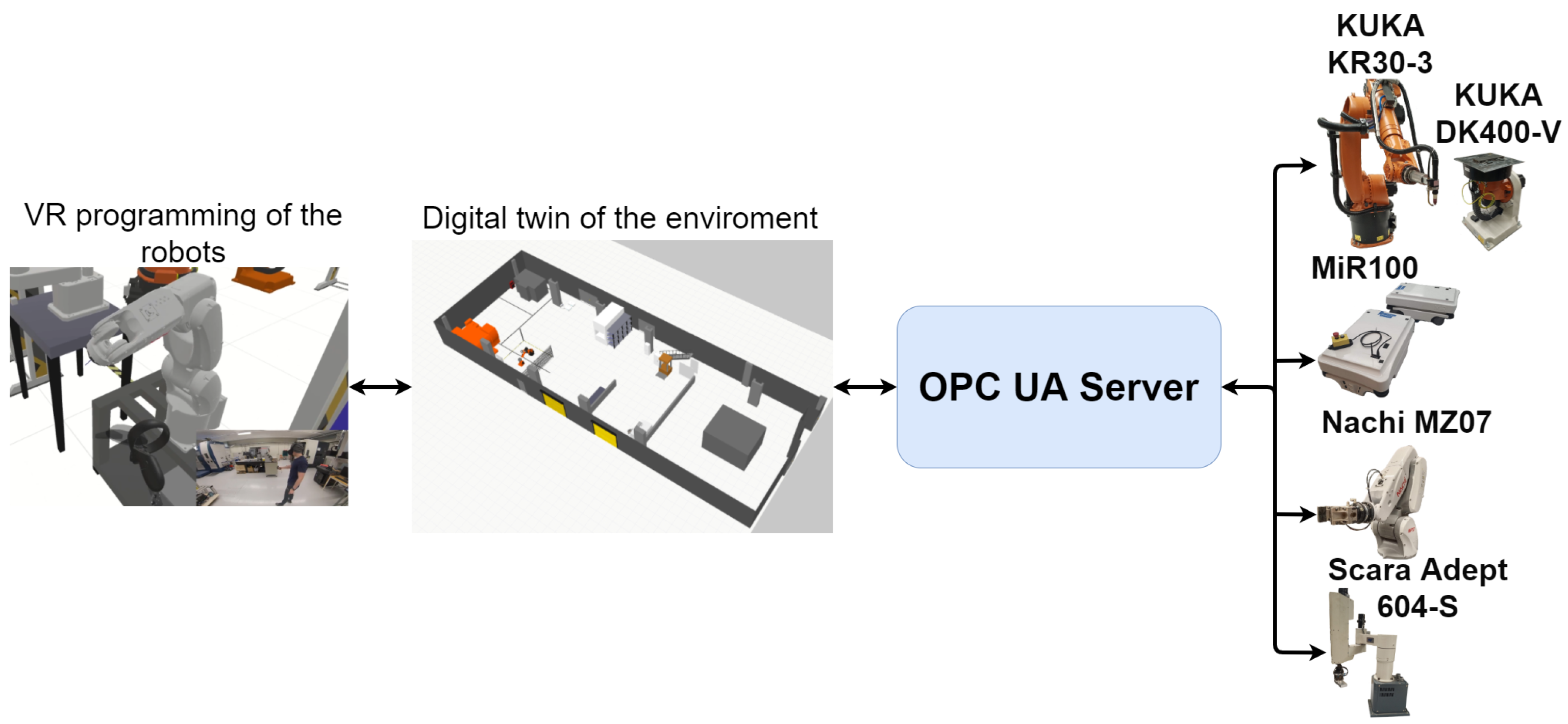
2.6. Virtualization of a Robot Cell for Training and Production Prototyping

While simulation is useful for synthetic data collection and evaluating IIoT networks, it can also be an integral part of training and production prototyping [34]. The solution titled virtualization of a robot cell for training and production prototyping focuses on the control of simulated manufacturing hardware using a real controller. The simulated hardware is represented in a real-time 3D-environment, which can be used for demonstrating actual system functionality, training employees, virtual commissioning, and testing production operations for new parts. These activities can be performed before the system even exists or after commissioning when they can be performed without disturbing the ongoing production. Since the control software used is identical to the real-world control software, all production master data created with the virtual system can be applied to the real one.
The Fastems cell controller, used for this solution, is an industrial PC that is used to host the manufacturing management software (MMS). It is identical to the one used to control real manufacturing hardware. The cell controller can also be housed inside a TouchOP human–machine interface (HMI-device), which provides the user with a screen, keyboard, and mouse that can be used to interact with the MMS user interface. Otherwise, a separate set of these peripherals is required. The cell controller also includes a Fastems specific connectivity solution, which allows the Fastems 8760 Support and user to connect to the system remotely. The 3D environment is run on a second PC and after the model is configured and running it does not require any additional user inputs. Therefore, only a screen is required for this PC. A virtual reality headset can be attached to allow the user to walk around the virtual system. There are no specific system requirements for the PC, but it must meet the minimum requirements for running Visual Components 4.2. Higher graphical fidelity and VR capabilities require a more powerful PC but are not required to utilize the module. Additionally, multiple PCs and screens can be connected to the system to view and interact with the MMS user interface. These PCs can be used to add and edit master data, view and create production orders, import numerical control programs, view the key performance indicators (KPIs), etc., locally or remotely. The screens allow the user to display the virtual model or, e.g., system KPIs to a larger audience. These screens are not considered to be a part of the module and are purely optional.
The key element of this solution is that the control software acts as if it is controlling a physical system. This way, the behavior of the system stays identical between the physical and virtual counterparts. It also means that all of the skills learned in the virtual environment will directly translate to the physical one and vice versa [35]. The module simulates production on a flow/process level and does not simulate the internal processes of machine tools or other similar devices in the system.
Three main KPIs were evaluated during the evaluation: re-configure time, training time, and labor safety. These KPIs were evaluated because they directly measure the ability to keep the system and personnel in productive use. Thus, the evaluated KPIs also indicate the business case viability for this module.
The re-configure time was defined as the time saved (%) when configuring the cell using a virtual counterpart instead of the physical cell. This can be measured in two datasets, in which the first is performed with the virtual cell and the latter is performed with a physical cell. The time saved is the difference in times between these two. The estimated result for this KPI was that around 20–25% of the required reconfigure time can be saved with this solution. The practical impact of this depends on the frequency of the system reconfiguration. In cases where there are frequent production changeovers and the introduction of new parts, the benefit can be substantial despite the relatively low KPI value. Training time was defined similarly to the re-configure time. It was defined as the production time saved when employees are trained with a virtual system instead of a physical one. This is measured as the amount of training time that can be carried out virtually. The result of this was estimated to be around 80%. Despite the high KPI value, there are always some minor topics that require physical interaction with the actual system. Since the productivity loss resulting from training is now reduced, the employees may be trained more often which leads to a more competent workforce. Labor safety was closely connected to the training time as it is the percentage of time that operators can do work outside of the factory floor or other hazardous environments with the virtual system. The majority of the benefits from this KPI come from the reduction in employee absences from productive use due to injuries or sick leave.
The module is already suitable for offline operator training in agile production environments but requires further development to improve its applicability in more complex robot system deliveries. According to the EU innovation radar [36] the proposed solution can be seen as being ‘Advanced on technology preparation’. This means that further development on system component-level optimizations is still needed to ensure the viability of the module business model before bringing it to market.

2.7. VR Programming of Manufacturing Cells

The agility of the manufacturing sector can be increased with simulated environments in multiple ways [37,38,39,40]. This module presents a solution for offline and remote robot programming by using digital twins, VR, and IoT. Robot programming can be time-consuming, requires expertise, and can be expensive. Furthermore, it can be dangerous for inexperienced workers to program and use industrial robots, and teaching new operators requires robots, which could occupy the ones in the manufacturing lines. The use of multiple robots from different brands presents another challenge, as each brand has its own system and programming methods, which can make it difficult for them to communicate with each other.
The presented solution first builds a digital twin of the environment and digital models of the used robots. In addition, a virtual control panel is added for each of the robots. By using VR, it is possible to move and drag the robot’s tool center point (TCP) to its desired position and program the robot. To program the robot arms, the VR controllers are used to pull the TCP point to the desired location and save the waypoint by pressing the button on the virtual control panel. There are also buttons on the virtual control panel for deleting/changing waypoints and gripping objects. Moreover, it is also possible to run the program with the virtual robot arms to see the movement. To program the mobile robot, the user moves through the virtual environment of the laboratory and uses the VR controller to add positions. When a position is added, a yellow marker is created to show where the mobile robot will move. The digital twin environment is connected to an IIoT server (OPC UA). Therefore, when the virtual robots have been programmed and the programs have been validated in the digital twin, the robot programs can be transferred to physical robots. Moreover, since the system uses IIoT, it is possible to program the robots remotely and then transfer them to the physical robot.
To demonstrate how this system works, three industrial robots and a mobile robot have been added to a digital twin, as shown in Figure 6. All of these robots can be programmed in the virtual environment separately or they can be programmed together. When the programs have been created, they can be transferred to the OPC UA server and directly executed on the robots. A video showcasing how all the robots can be programmed can be found at https://www.youtube.com/watch?v=wG8npG-Lxd0 (accessed on 28 June 2023).
In robotics, VR facilitates a cost-effective concept prototyping in safe environments, emphasizing safety and utilizing collision detectors to alert trainees to risks without real-world harm [41]. Building on this foundation, the system we have designed serves as a proof of concept that showcases how different technologies can be used together. We demonstrate how VR can be employed as a simple, intuitive, and safe method for robot programming in teaching. Additionally, the use of the OPC UA standard enables communication and control across different robot brands, fostering machine-to-machine communication. This can further allow the development of a control interface compatible with various robot arms, thus enhancing versatility and interoperability within the field.

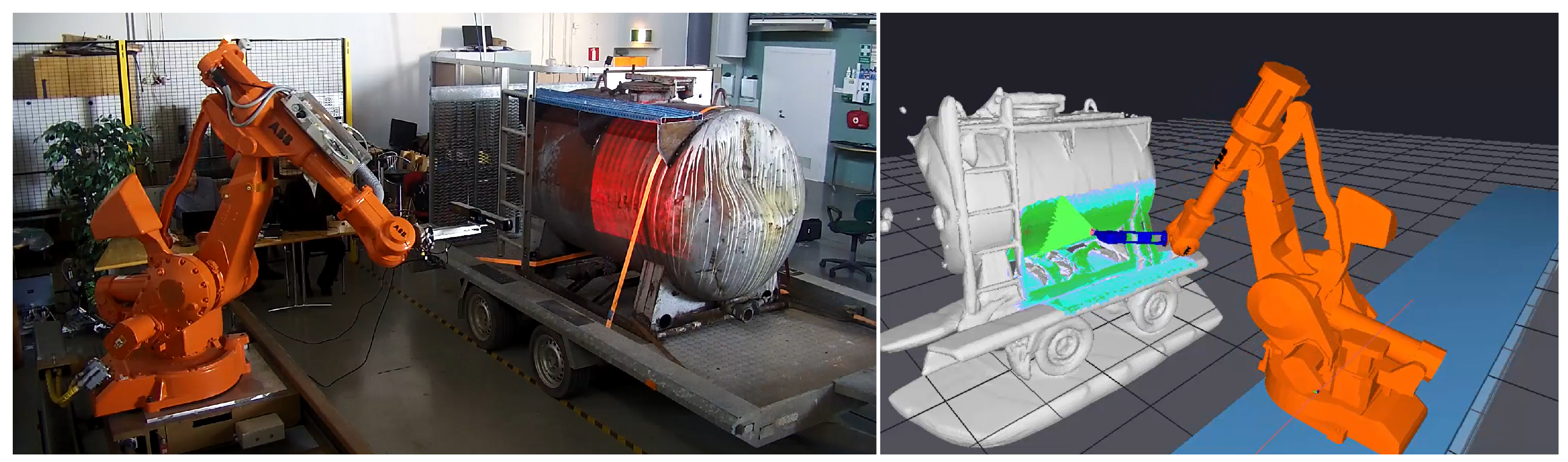
2.8. Online Trajectory Generation with 3D Camera for Industrial Robot

The next presented solution further expands robot programming in a VR environment by looking at physically large objects, such as heavy equipment or a major element of a building. Programming trajectories using a teach pendant requires the programmer to climb on the structures or to utilize a lift to visualize the object in order to record trajectories. Working on top of high objects exposes the programmer to physically hazardous situations; tripping and falling caused 18% of non-fatal work injuries in the US in 2020 [42]. While programming the trajectories, using offline simulation software removes the programmer from the dangerous environment. Offline programming requires either an existing digital model of the object being processed or manual scanning of the object. Drafting a digital model or manually scanning the existing product to create one is a time-consuming and unnecessary phase. To avoid exposing the programmer to hazardous situations and drafting a digital model of the existing work object, online trajectory generation input using the output of a 3D scanner is presented. In addition, the presented approach consists of reactive generation of robot trajectories saving time consumed on manual programming of the trajectories.
The demonstration setup for this proposed solution consists of a large-scale industrial robot, a 3D scanner mounted on the robot flange, a cylindrical reservoir as a work object, and a workstation PC. AUTOMAPPPS [43,44] reactive offline programming software is installed on the workstation PC to use the processed point cloud data from the 3D scanner as a digital model and generate the trajectories for the robot. The 3D scanner connects to the workstation PC using a USB connection, and the robot connects to the PC utilizing an Ethernet connection. The communication between the robot controller and the simulation software enables the digital shadow of the robot [15]. The interface to the scanner was implemented using a software development kit (SDK) by Photoneo [45]. The demonstration setup is presented in Figure 7.
The controlling software installed on the workstation PC initiates scanning of the object from the outer regions of the predefined working space to avoid collision between the camera and the scanned object. The idea is to systematically generate a point cloud of the object, moving from the features farthest away from the object’s center point to those closer to the object’s center point. As a result of the scanning process, a point cloud of the object is created, and the next phase is the 3D model creation followed by the reactive generation of the trajectories. In this setup, the aim is to generate trajectories to pressure wash the reservoir. Reactive generation maintains a pre-defined distance and angle to the object surface to achieve optimal cleaning results. Collision-free path planner also avoids typical obstacles such as ladders on the surface. After the reactive generation of the trajectories is complete, linear, circular, and point-to-point commands are uploaded to the robot controller, and the robotized pressure-washing process starts.
It is possible to utilize the presented online trajectory generation methods for similar industrial processes, such as sandblasting and painting. In addition, the presented solution can be scaled to physically larger objects such as trucks and earth-moving equipment. In Finland, an SME is piloting the solution to develop an autonomous drive-in heavy truck washing facility. The piloting facility is based on the presented approach and is currently in the test phase.
The presented solution includes a digital shadow of the robot station. In addition to the robot’s digital shadow, a digital shadow of the object being processed is created during the process. Including work object shapes in digital shadow or a twin with physically smaller objects has been presented previously by [46,47]. As quantitative metrics, the following key performance indicators have been measured in real-life robotized applications. The production lead time from the start to the manufacturing of the final product is reduced to 10–60 min if compared to conventional programming, which typically takes 60 to 240 min. Time reduction is dependent on the product’s complexity. With the proposed solution, the set-up time is reduced to 45–120 min compared to the conventional programming approach, which requires at least three days, depending on the complexity of the work object. In non-robotized washing applications, water consumption is typically thousands of liters with large objects, while water consumption is reduced to some hundreds of liters with the proposed solution. In addition, manual labor has been completely removed from hazardous environments.

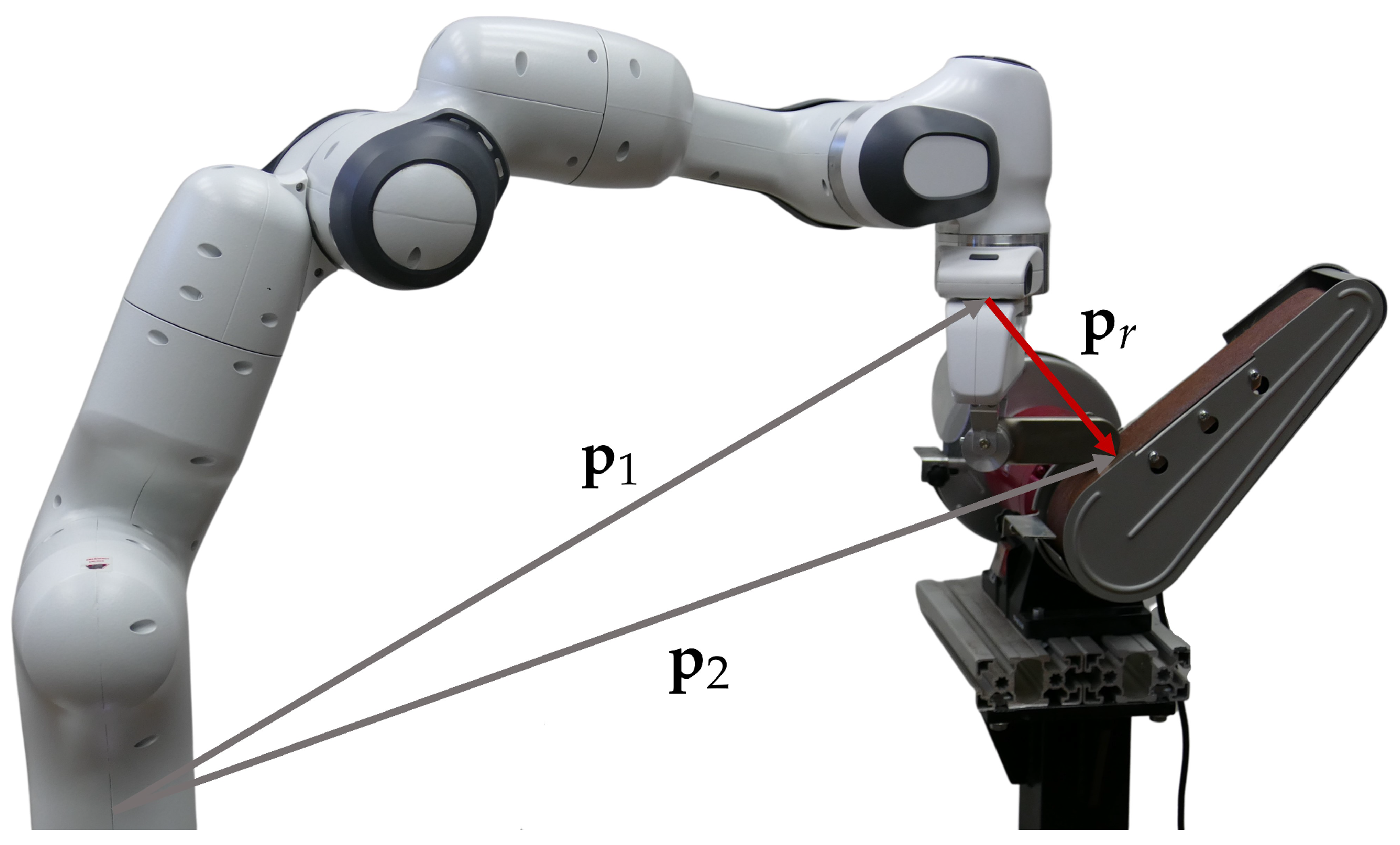
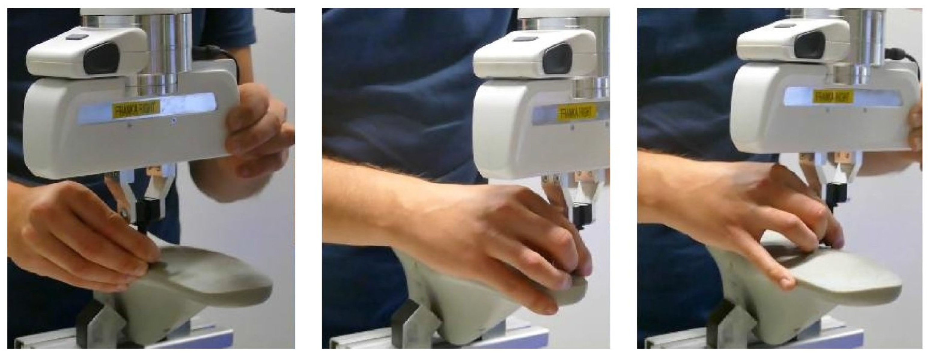
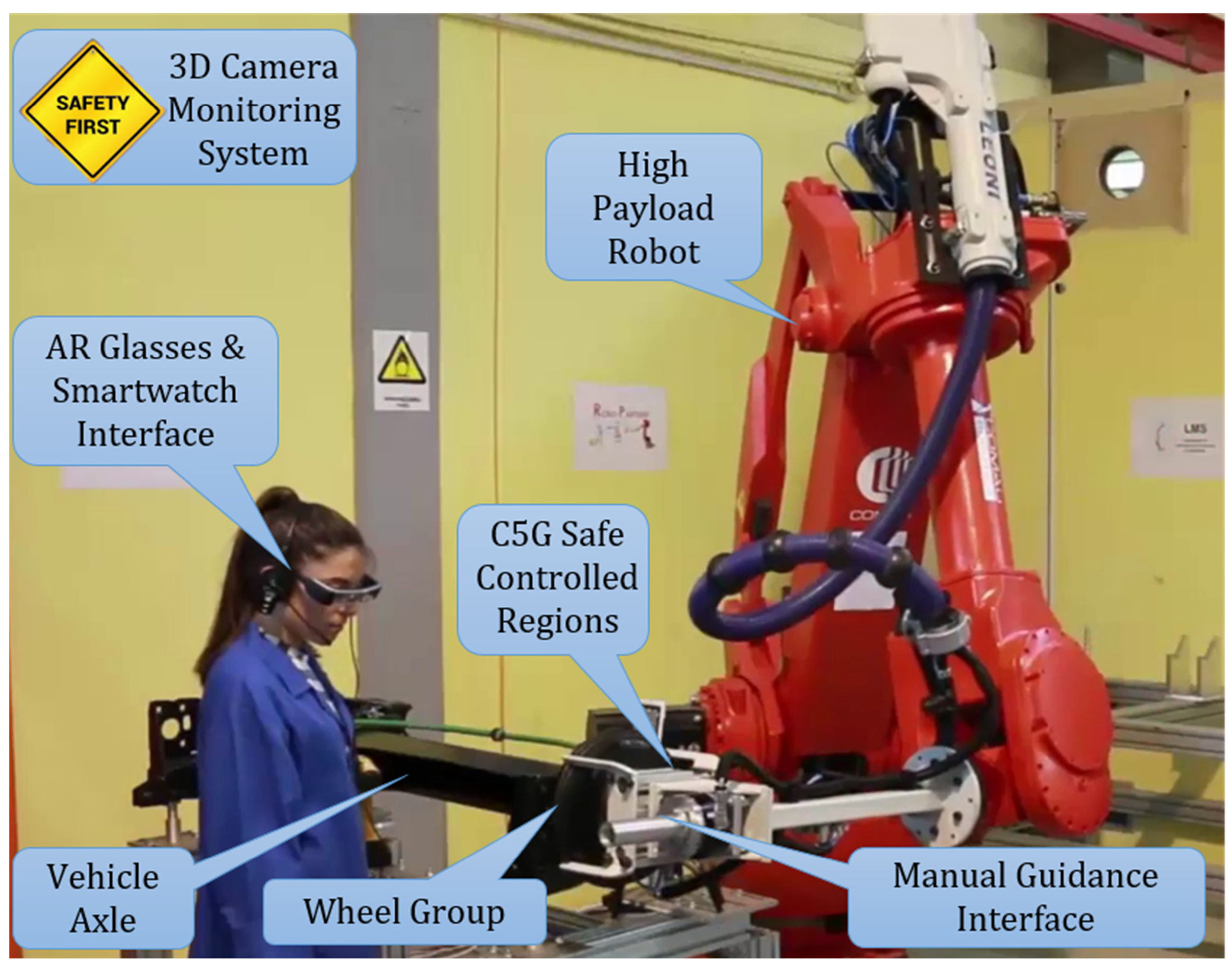
2.9. Robot Programming of Hard to Transfer Tasks by Manual Guidance

This solution address the challenges of robot programming in a human–robot collaborative environment or, more precisely, programming hard to transfer force-based skills by manual guidance, i.e., human demonstrations. It provides a software and hardware framework that includes both front-end and back-end solutions to integrate programming by demonstration paradigm into an effective system for programming force-based skills. The proposed approach is based on the manual guidance of a robot by a human teacher to collect the data needed to specify force-based skills and consists of two main components: virtual mechanisms and incremental policy refinement [48]. Among the common industrial tasks that can be automated this way are grinding and polishing. Their successful execution relies on the application of proper forces and torques that are exerted through a hand-held tool on a treated surface. The transfer of human expert skill knowledge requires the acquisition of both position and force data. We used various sensing devices for this purpose, e.g., a digitizer equipped with force/torque sensors. Once the data is captured and converted into the desired skill, the skill is executed using the concept of a virtual mechanism, which takes advantage of redundancies stemming from the task and the tool shape [49]. This approach defines a bimanual system consisting of the robot executing the task and the tool, where the tool is modeled as a robot (see Figure 8). The relative position p r and orientation q r of a bimanual system’s end-effector are defined as,
p r = q ¯ 1 ( p 2 p 1 ) , q r = q ¯ 1 q 2 ,
where p 1 and q 1 denote the position and orientation of the robot’s end-effector, p 2 and q 2 of the tool mechanism’s end-effector, q ¯ the quaternion conjugate, and ∗ the quaternion product. The relative pose is used to control the robot via joint velocities.
The effect of the virtual mechanism was evaluated on an industrial robot performing a polishing task, i.e., moving a faucet handle and polishing the edges on a rotary polishing machine. The desired point of task execution, in our case the polishing machine, was moved to several different locations inside the robot’s workspace, with the height and orientation remaining constant. The learned task was executed at each of these locations while joint velocities were recorded. The evaluation showed an increase in the robot’s workspace, where the task can be performed, and a significant drop in peak joint velocities.
To reduce the time required for the deployment of robotic skills, it is beneficial if the acquired skill knowledge can be reused. In our system, we make use of incremental learning from demonstration (iLfD) and reversible dynamic movement primitives (DMP) to create a framework that enables the reuse of existing skill knowledge [48]. To assess the effectiveness and efficiency of this approach, we conducted a user study on a case from the shoe manufacturing sector. While the movement for a shoe grinding task was already learned, the users had to teach an appropriate robot movement through manual guidance for a different shoe size (see Figure 9). Two approaches were used: (1) classical manual guidance, where the user had to teach the task from scratch, and (2) the proposed incremental learning, where the user adapted the previously learned movement. With the proposed approach, the position p and orientation q send to the robot controller are defined as,
p q = p ^ + d p exp 1 2 d o q ^ ,
where p ^ and q ^ represent the original pose, while offsets, learned through incremental refinement, are denoted as d p and d o . With the classical approach, users needed several full demonstrations to teach the appropriate movement. With incremental learning, subjects made only one learning attempt but were able to correct any deviations in the previously learned path incrementally. They were also able to additionally demonstrate the speed profile. The results showed that incremental learning, compared to classical manual guidance, reduces error, shortens learning time, and improves user experience.

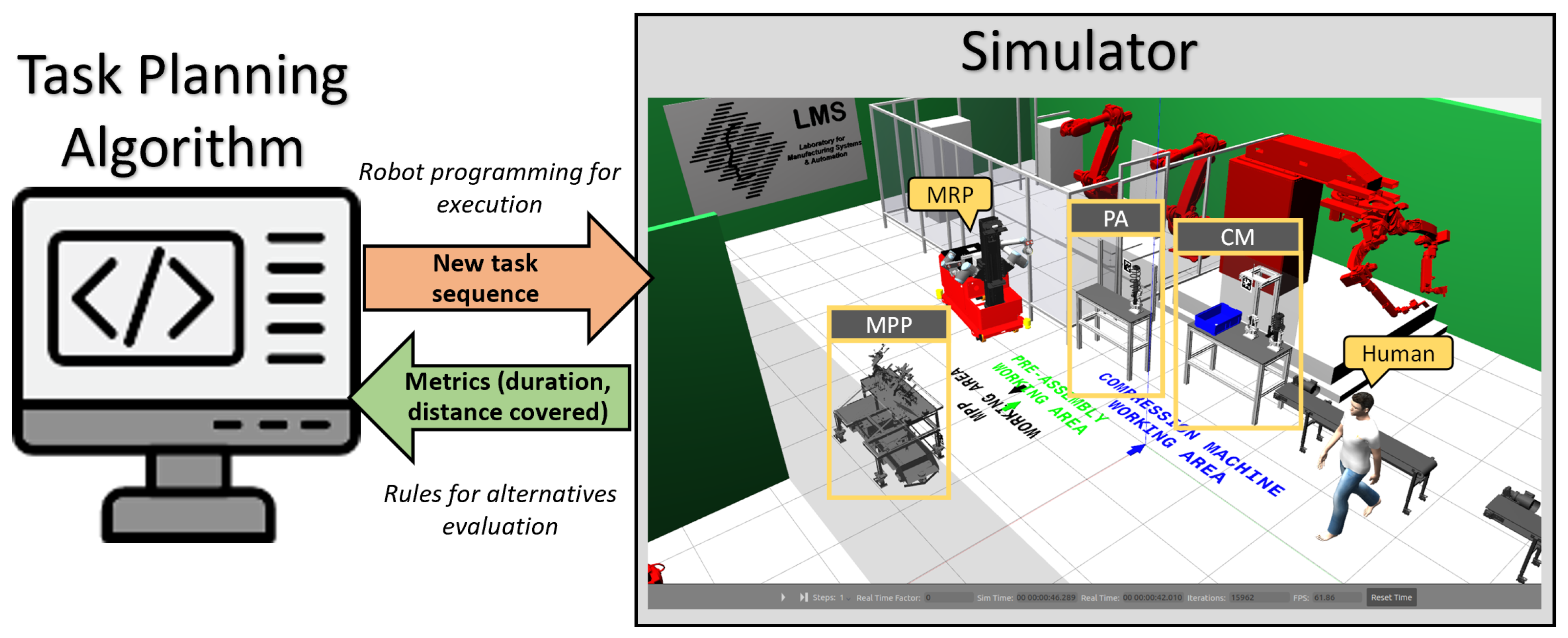
2.10. Dynamic Task Planning & Work Re-Organization

Agility in the manufacturing process can be increased by further taking advantage of human-robot collaboration [50]. Both agents can share the workspace and perform the same/similar tasks. In order to overcome the time-consuming process of designing a new human–robot task allocation plan and reducing the time and size of the design team needed for applying a change to an existing line, this module suggests a solution based on a multi–level decision-making framework targeting the dynamic work-balancing among the human operators and robotic resources.
The implemented framework provides optimal scheduling of a predefined set of assembly tasks, by assigning them to available human and robotic resources (mobile or stationary), while also enabling motion planning for the robotic operators. The system is able to gather information about the workflow and the physical environment through a Digital Twin and construct task plans that are feasible, time-efficient, and ergonomic for the operators. While generating alternative schedules, the embedded AI algorithm utilizes both static and simulation data to evaluate the plans and output an optimal one (Figure 10). Through the proposed framework, 3D graphical representation of the environment, process simulation, and embedded motion planning for both humans and robots are provided to support and further enhance the scheduling.
The proposed architecture was tested in a case study inspired by a production line in the automotive industry. Three KPIs were measured to evaluate the planning procedure, including re-configure time, labor safety, and reduction in waiting time. Re-configure time was defined as the average time for the task planner to generate and evaluate new alternative task plans based on new search planning parameters. The estimated result for this KPI was an average duration of approximately 3 min, which was measured through testing. The user via the UI stopped the planning, and the time duration was calculated from this time frame until the end of the planning parameters’ update and planner’s execution trigger.
Labor safety was defined as the total weight of the payload that the operator could handle during a generated task plan execution and to measure it, the reduction in the total weight that the operator handles during the execution of each generated task plan was calculated leading to a result of approximately 50% reduction.
Finally, reduction in waiting time is defined as the reduction in the idle operator time waiting for parts and products to become available or being processed and it was calculated by measuring the operator time during the execution of each generated task plan. The result was that the operator idle time was minimized to almost 60% of the initial idle time.
In conclusion, the proposed decision-making framework demonstrates significant potential to enhance production agility and efficiency within hybrid production systems. By seamlessly integrating task scheduling and resource motion planning, the solution offers a robust, industry-ready approach that addresses the challenges of modern manufacturing environments. The successful application of this framework in a real-world scenario underscores its ability to drive innovation and elevate the state of the art in human–robot collaboration.

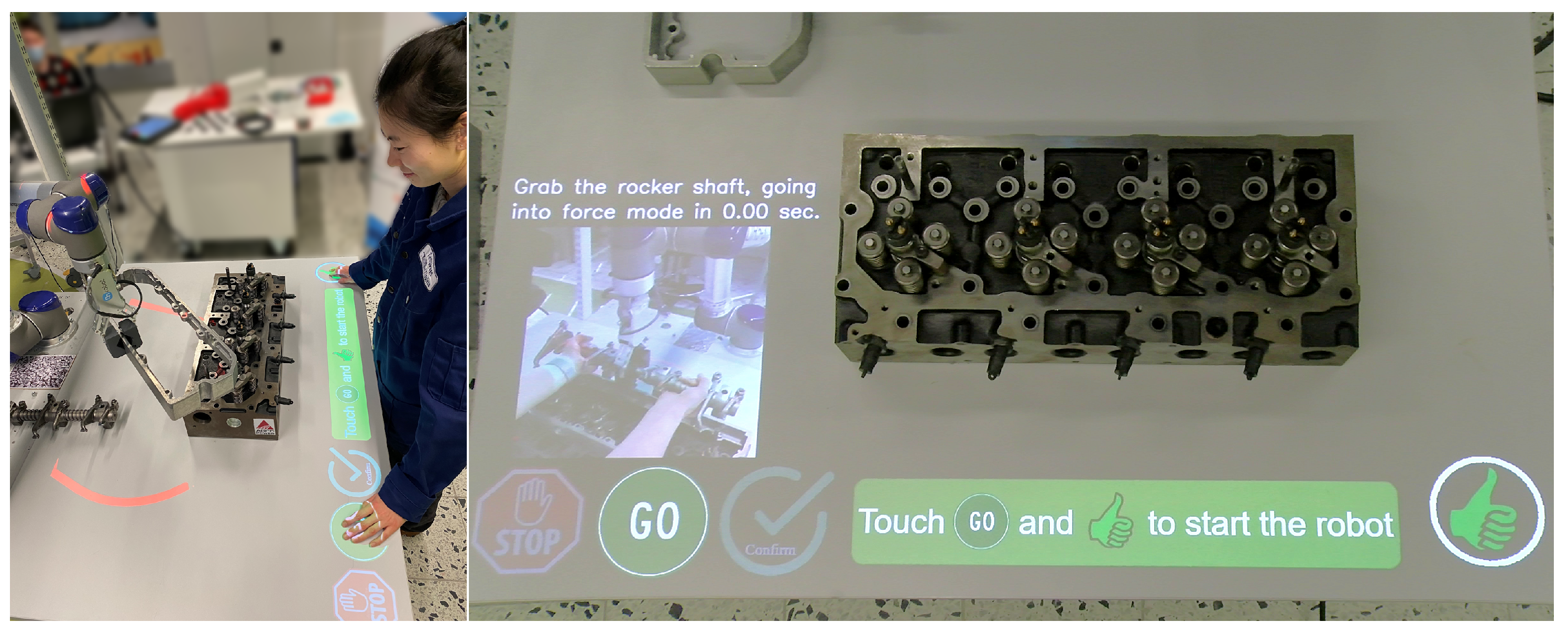
2.11. Projector Based GUI for HRC

As mentioned, task sharing in human–robot collaboration can increase the agility of manufacturing. When tasks are shared in the same working area and the product being manufactured is constantly shared by the operator and the robot, the cognitive load of the operator increases considerably. The human safety aspect also needs special consideration in such a setup. As the human needs to focus on his or her own task while similarly keeping an eye on the robot’s actions, it is very demanding to keep the focus on important and relevant topics. As the field of vision needs to be on the performed task following instructions on a separate screen is difficult, especially if the collaborative area and the product being manufactured is large. The collaborative application may also require two hand operations, so giving inputs to the robot, such as pressing a button, is demanding. The proposed solution combines these features by proposing a projected interactive user interface for human–robot collaboration, as shown in Figure 11.
The module is part of a demonstration setup of a vision-based safety system for human–robot collaboration in the assembly of diesel engine components. A dynamic 3D map of the working environment (robot, components + human) is continuously monitored and updated by depth sensor and utilized for safety and interaction between the human and the robot with virtual GUI. The robot’s working zone is augmented for the user to provide awareness of safety violations. Virtual GUI aims to provide instructions for the assembly sequence and map proper UI as the controller of the system.
The workspace is monitored by the Kinect v2 sensor, which can be installed at the ceiling overseeing the whole working area. A standard 3LCD projector is used to project the safety borders and the user interface components on the working tabletop. The system is ROS-based running on a single laptop computer with the ROS Melodic distribution. It uses a modified version of ur_modern_driver and universal_robot ROS packages to establish a communication channel between the robot low-level controller and the projector ROS node. The iai-kinect2 ROS package is used to receive data from the Kinect-2 sensor and further transmit it to the projector node. The sensor monitors the activation of the interface components. The projector node is responsible for creating RGB images of the current status of the workspace for the projector and sending start and stop commands for the robot controller. Robot joint values are used to calculate the shape and position of the safety border. The information area content and the interface buttons are based on the system data. To help the operator, the projector interface provides instructions on how to execute the current task. Research has shown that tasks performed with the help of the safety system can be completed 21–24% faster. Robot idle time is reduced by 57–64% [51].
Using a vision-based safety system can decrease operator violation of robot safety zones by decreasing the possibility of human error. As a result, this can lead to reduced production cycle time, where a human does not stop production lines by these mistakes. Here, proper GUI notifies the human of the violating robot’s working zone and assists the human to avoid this error. Based on user tests and surveys, both scenarios have vision-based safety systems compared to the baseline, where the robot was not moving in the same workspace with an operator. The result of this experience can be explained by measuring the robot’s idle time and total execution time.
To sum up, the proposed projection system provides a new approach for flexible user interfaces in human–robot collaboration. As part of a vision-based safety system, the interface can increase HRC production cell performance while maintaining operator safety. The system has been tested with small collaborative robots where the projection surface is the tabletop. Currently, we are working on scaling up the system to full-size industrial robot work cells, where the UI will follow the operator on a movable table.

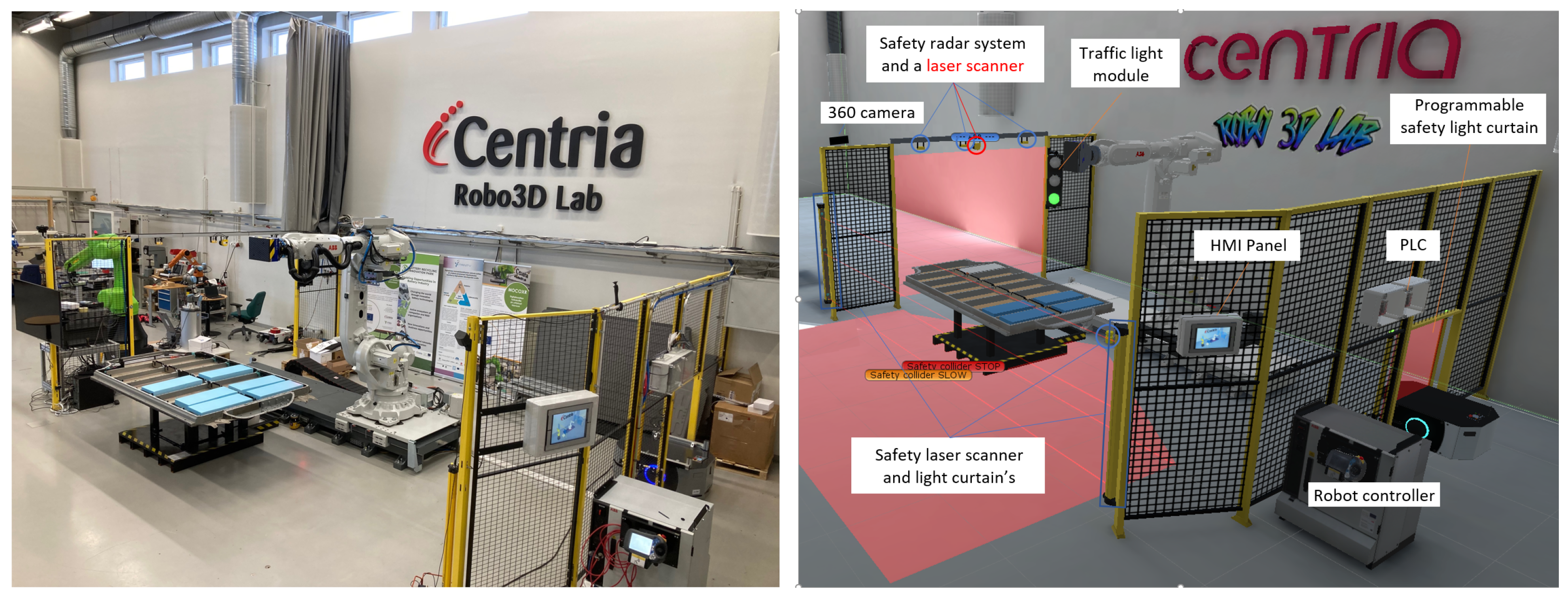
2.12. Safe Human Detection in a Collaborative Work Cell

Human safety is paramount in a human–robot collaborative work cell. Isolating the robotized production cell with physical fences and locked doors is a conventional solution to guarantee the safety of the human workers sharing the production floor with robots. While physical fences and locked doors provide a high degree of safety, the disadvantages are a static requirement of floor space and the inflexibility of human–robot collaboration (HRC). As an alternative approach, safety devices allow the dynamic use of floor space and flexible HRC. Laser scanners, programmable light curtains, and microwave radars are safety-approved devices that enable fenceless and highly configurable safety areas for robotized production cells. Safety standards help to minimize the risk of injury to people who work with or around robots. Existing standards ensure that robots meet minimum quality, reliability, and functionality levels. They can also help developers and customers compare different robots and select the best one for their needs. In addition, standards help regulatory bodies develop appropriate guidelines for using robots in different contexts, such as manufacturing. Despite the importance of standards, standardization is needed behind the fast evolution of new technologies that enable safe human–robot collaboration. Standardization is typically a slow and time-consuming process involving multiple parties and organizations. The presented module includes multiple approved safety devices enabling standardized and flexible safety solutions. The flexibility is further enhanced using additional safety devices.
The module provides a solution for setting up the safety zones of an industrial robot production cell featuring flexible use of the cell. Safety is achieved by utilizing multiple safety devices in a single production cell and defining multiple safety zones in the work cell shared by robot and human workers. The first zone, physically further from the robot, slows down robot movements allowing the robot to continue working. The second zone, physically closer to the robot, stops the robot. The module utilizes commercially available safety products to create safety zones and detect human workers’ locations in the robot cell, ensuring their safety by slowing down or stopping the robot as it approaches the robot. The module also provides information about the work cell status to the end user; for example, by utilizing visual or audible signaling devices. In addition to configured safety zones, areas are monitored utilizing duplicated safety devices, and the user can choose which devices are more suitable for the current task.
The demonstration setup at the Centria production automation laboratory consists of a large-scale articulated industrial robot and a linear track; the setup is presented in Figure 12. Since there is a wall behind the robot, it is possible to approach the robot from the left, right, and front. The front side of the robot is monitored by a laser scanner installed at the center of the linear track base and a safety light curtain in front of the robot cell. The laser scanner has two programmed safety zones; the first is programmed to slow the robot’s motion if a human worker is approaching the robot but is still outside the robot’s reach area, and the second is programmed to stop the robot if the zone is entered. The safety light curtain is a secondary safety device utilized if an obstacle in front of the robot blocks the safety laser scanner.
A programmable safety light curtain monitors the right-hand side approach direction and is configured to allow specific shapes to enter the robot’s reach area. In this case, the light curtain is programmed to allow only a specific mobile robot to enter the robot cell. Additional shapes can be programmed in the future to enable, for example, a four-legged mobile robot to access the cell.
A horizontally mounted laser scanner and three microwave radar units monitor the left approach direction. Fog, dust, and smoke can cause optical sensors, such as a laser scanner, to cause false intrusion detection in industrial environments. Microwave radars are immune to the aforementioned factors and are utilized to prevent false detection. By using a microwave radar system and a laser scanner, it is possible to improve the total reliability of the safety system.
The safety-approved devices connect to digital inputs and outputs of an approved programmable logic controller (PLC). The PLC is connected to the industrial robot controller using a bi-directional field network connection. A touchscreen human–machine interface (HMI) panel enables workers to visualize states, reset tripped safety devices, and select between the duplicated safety devices. In addition to the HMI, a traffic light module featuring green, orange, and red beacons is installed in the robot station to signal the human workers about the state of safety devices. Green, orange, and red lights indicate normal operation at full speed, violation of the outer zone and robot speed is reduced, and violation of the reach area and the robot is stopped, respectively.
In addition to the safety-approved devices, additional safety devices were developed as reported by [52]. An indoor positioning system based on Bluetooth 5.1. standard (BLE) enables direction-finding features, allowing centimeter accuracy in indoor positioning. This can be used to enhance safety while operating in robotized environments. This technology allows real-time tracking of both mobile robots and people operating in the same environment. Moreover, 360° cameras allow the monitoring of horizontal and vertical directions on a unit sphere using a single shot capture. Combined with machine learning, people can be detected in real time with high accuracy. Additional safety devices contribute to agile manufacturing by enabling the detection of human workers inside the production environment.
This module also connects to previously mentioned solutions regarding training and programming in a VR setting; see Section 2.6 and Section 2.7. By implementing a digital twin [53] of the demonstration setup, virtual HRC training and a robot station risk assessment is possible. The digital replica of the robot station was created using Unity3D [54] and the development is reported in [55]. The bi-directional communication layer bridges the physical and digital twins together to enable realistic safety training in the virtual environment. The communication layer is based on the MQTT-protocol [56] transferring robot and safety device status and control data between the twins.
Transitioning from collaborative robots to heavy industrial robots can pose significant risks and potential harm to operators. In the context of shifting to larger-scale layouts within industrial environments, the integration of VR training emerges as a potent solution. This approach enables risk-free practice in complex setups, thereby improving spatial awareness and overall operational performance. An example of this application can be observed in work by Mastas et al. [57], where a highly interactive and immersive virtual environment was utilized for assembly training with smaller industrial robots, addressing safety concerns such as contacts and collisions.
To investigate the transition of mid-heavy component assembly to robots, an HRC (human–robot collaboration) pilot was established at Tampere University’s laboratory, focusing on engine assembly. This collaborative cell follows a coexistence application, where humans and robots perform tasks separately. However, to enhance productivity and efficiency by utilizing a larger and faster industrial robot compared to cobots such as the UR5, we explore the levels of speed and separation monitoring for collaboration, following ISO/TS 15066 [58] guidelines.
A comprehensive risk assessment of this cell was conducted, and layout optimization was achieved through iterative processes within a digital twin replica using simulation software. Laser scanners are integral to the safety system, tracking human positions in relation to the robot’s movements. After iterative considerations and safe implementation, the integration of a single laser scanner was determined. Safety distances play a crucial role, necessitating the strategic positioning of the engine to limit the robot’s access and minimize potential hazards as identified in the risk assessment. This critical phase led us to employ a systematic approach, employing the ISO 13855 [59] standard equation (Equation (3)) for calculating safety distance S in the horizontal detection zone as
S = ( K × T ) + 8 ( d 14 )
where K is the approach speed (of hand or body) in mm/s, T is the stopping time of the machine (including reaction time of safety devices) in seconds, and d is the light curtain’s resolution in mm.
The ABB IRB 4600 manuals aided in determining stopping times based on category one extension zones, while the laser scanner’s technical specifications guided its detection capability assessment.
Consequently, two zones were defined to control robot speed. Additionally, light curtains were integrated to monitor any user’s entry into the collaborative space, enabling a protective stop of the system. Following the physical system setup, the virtual reality safety training concept, as discussed in [60], was developed using the UNITY game engine. This training aims to educate users about safety measures concerning robots and safety devices, including hazardous risks related to safety distances and boundaries. The VR application also highlights events that trigger human safety concerns. The feasibility study of the VR technology was conducted in collaboration with the robotics research group to analyze this integration. The study concluded that the VR training system offers significant benefits compared to traditional training methods, considering both use case and technical criteria. For further studies, KPIs such as time completion, training time, and number of violations of hazardous areas will be measured in a full assembly scenario.

2.13. Adaptive Speed and Separation Monitoring for Safe Human-Robot Collaboration

In the current industrial practice, physical fences and locked doors are the main safety measures that provide a high degree of human safety, but such methods do not boost the human–robot collaboration characteristic of the system. As presented in the previous Section 2.12, multiple safety devices can be integrated to introduce so-called digital barriers. The benefits of digital barriers, monitored by sensors, have become evident [61] as they increase the dynamic capability of the manufacturing cell, increase the use of current industrial tools that minimize the ergonomic risks for humans, and minimize the costs compared to physical fences. However, simply replacing physical fences with virtual ones does not ensure high flexibility in human-robot collaboration. The last presented solution tackling human safety addresses this by creating a human–robot collaborative cell (see Figure 13) with virtual fences around the industrial robot, rather than the entire cell. This increases the dynamic capability of the zone and minimizes the restricted area to only what is necessary for each production step, moving beyond the current state of the art. Additionally, this solution enables the integrators to use typical industrial robots and easily place them next to the operators, taking advantage of their capabilities and operating safely, instead of using certified collaborative robots that have limited capabilities, i.e., smaller payload.
To enable the aforementioned functionality, a complex architecture has been designed and implemented, comprising safety sensors, safety PLCs, and the robot controller. Central to this architecture is a safety-certified sensor, composed of three cameras, that oversees the workspace and detects the occurrence of any violation of the safety zones. Managing the exchange of signals, the safety PLC collaborates with the robot’s PLC, which transmits the robot’s operational status and identifies potential emergency situations. Beyond the hardware elements, intelligent algorithms have been integrated and executed within each device’s controller. Within the safety camera’s controller, all the sets of safety zones, referred to as zone arrangements, are designed. At the same time, the safety PLC is responsible for triggering a specific zone arrangement for the camera to monitor, according to the robot’s current position. The robot’s position is constantly communicated to the safety PLC by the robot controller, which also waits for safety signals to react in case of violation by regulating the robot’s speed or stopping the robot’s movement entirely. The safety system discussed above enables humans to work alongside an industrial robot in the same workspace while ensuring safe separation, and hence enabling collaboration with cobots that may not be certified for HRC applications. In contrast to conventional physical or stationary virtual fences utilizing light barriers, this system allows the operator an expanded workspace within the cell. By optimizing the robot’s working area and utilizing compact, dynamically adjusted safety zones instead of larger and rigid ones. This configuration increases the available working space for the operator enabling parallel operations alongside the robot and subsequently enhancing the overall cycle time. The assessment of the system under real production scenarios showed a 24% reduction in cycle time [62] for the examined production processes when shifting from fixed to dynamic safety fences, highlighting the benefits of this approach.
To sum up, the proposed safety system introduces an innovative method for facilitating secure human–robot collaboration. It establishes dynamic virtual boundaries around the robot, that follow the robot’s movement. The deployment of the proposed system results in more flexible and productive workstations by allowing safe and optimized co-existence and synergy between human and robotic operators.

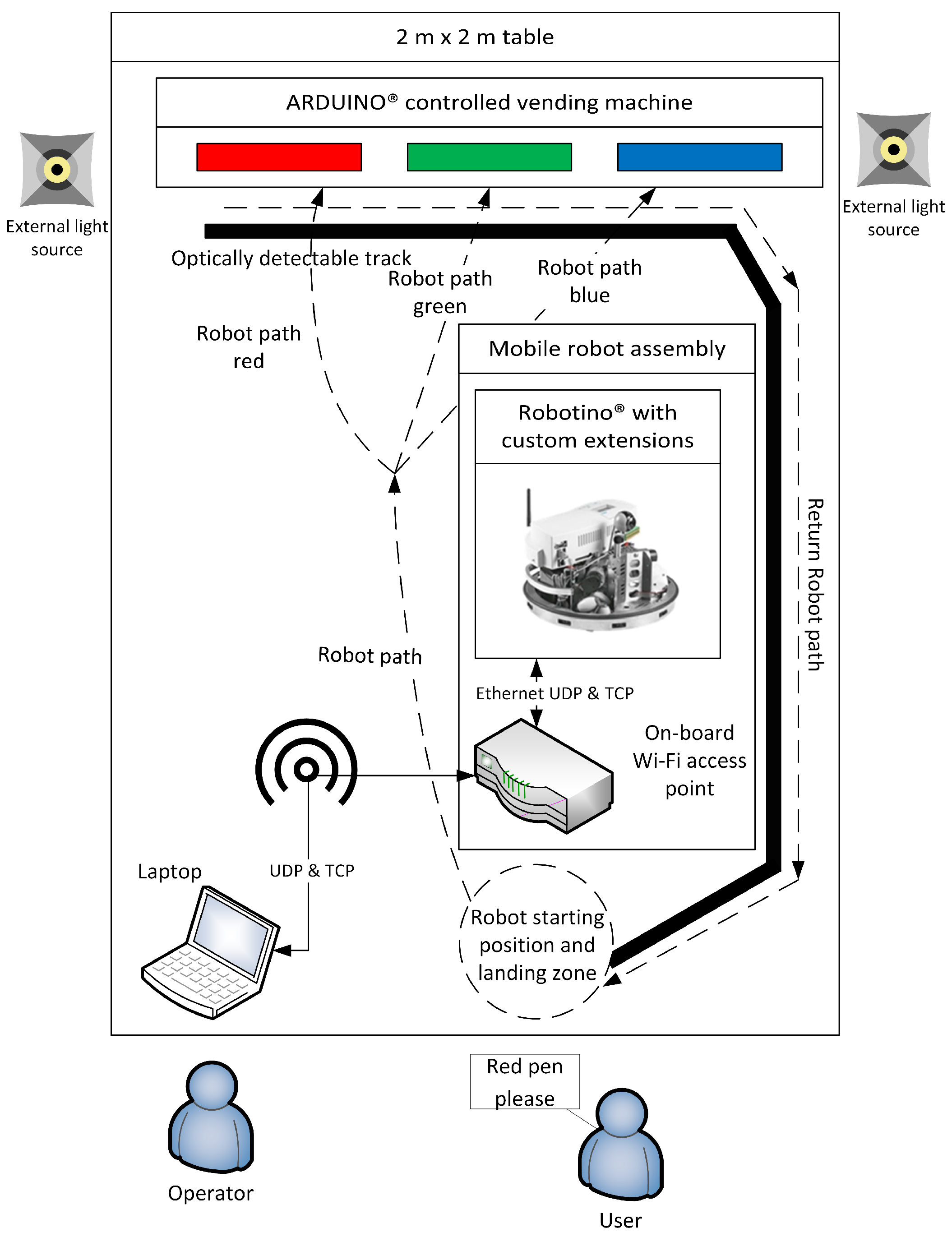
2.14. Mobile Robot Environment Detection

The last presented solution tackled in this paper: automated ground vehicles. Their use can increase the agility of the manufacturing process, especially if combined with other emerging technologies usable in intralogistics. The mobile robot environment detection module consists of three sub-modules. An overview of the system design can be seen in Figure 14. Each of these serves as an example of a type of basic interaction that should be implemented during mobile robot applications. The performance of the robot’s task, i.e., its movement, is basically generated based on the information available from the environment and observed from it, which in the case of this demonstrator, is represented by line tracking and camera image processing. In several cases, the robot must also communicate with external equipment, which is characterized by the exchange of information with the vending machine. And thirdly, instructions appear on the human-readable text card symbolizing the increasingly frequent human–robot communication, which appears in the form of image processing with optical character recognition (OCR). This solution, in the form of a demonstrator, offers testing, evaluating, and combining various technologies that enable the execution of various tasks by automated ground vehicles.

3. Conclusions

Several solutions for increasing the agility of the manufacturing processes are presented in this paper. In the area of robot work cell development, solutions for automating THT-PCBs and determining optimal placements and postures of reconfigurable fixtures are presented. Another area with a potential for increasing agility is simulation. We propose several simulation-based solutions including the generation of synthetic data for computer vision, where the presented module focuses on a bin-picking scenario. We also propose using simulation for designing and evaluating IoT networks, which play an important role in connected smart factories. A related solution uses IoT networks for predictive maintenance without undergoing standard digitization processes. By implementing a virtual robot cell, a simulation environment can be used for production prototyping and training, which drastically reduces the downtime of the production line. If simulation is enhanced with digital twins and VR, it can be used efficiently for programming of work cells and robot programming, e.g., trajectory planning for physically large workpieces. To ease the programming of hard-to-transfer force-based tasks, one of the presented solutions leans on programming by demonstration, where manual guidance is used. Some other solutions deal with human workers that share tasks in a common workspace with a robot, thus requiring human robot collaboration. One of our solutions dynamically allocates tasks between agents, while another presents relevant information to the human worker via a projected GUI. As human safety is paramount in human–robot collaboration, a lot of solutions in this paper focus on it: how to use various sensors to detect humans without the need for physical barriers, how to use this information to execute safe robot movements, and the use of aVR settings for safety evaluation. The area of automated ground vehicles is also touched upon with a demonstrator combining various emerging technologies.
The proposed solutions stem form the EU-funded TRINITY project and are focused on increasing the agility of the manufacturing sector. To design these novel technologies, they implement methodologies that show promise and are at the cusp of industrial integration. To ease implementation they were (re)designed as stand-alone modules. They are currently at least TRL 5 and exploit several key paradigms from the robotics and AI sectors. They were validated through various manufacturing-related KPIs in the relevant industrial settings and further improved and adapted. As part of laboratory testbeds, they enable further analysis, adaptation, and evaluation prior to industrial implementation. As the main targets of our work are SMEs, they are designed with affordability and ease of use in mind. By making them modular, easy to implement and test, well-evaluated, and affordable, the proposed solutions can benefit the manufacturing sector by increasing the agility of industrial production.

Author Contributions

Conceptualization, M.D. (Miha Deniša), A.U., M.S., T.K., T.P., S.P., J.A., J.J., K.O., L.R., A.C., M.D. (Morteza Dianatfar), J.L., P.A.S., A.M., A.S., H.A., B.S., D.D., P.K., T.-P.A., V.V. and M.L.; Data curation, M.D. (Miha Deniša), A.U., M.S., T.K., T.P., S.P., J.A., J.J., K.O., L.R., A.C., M.D. (Morteza Dianatfar), J.L., P.A.S., A.M., A.S., H.A., B.S., D.D., P.K., T.-P.A., V.V. and M.L.; Formal analysis, M.D. (Miha Deniša), A.U., M.S., T.K., T.P., S.P., J.A., J.J., K.O., L.R., A.C., M.D. (Morteza Dianatfar), J.L., P.A.S., A.M., A.S., H.A., B.S., D.D., P.K., T.-P.A., V.V. and M.L.; Funding acquisition, A.U., K.O. and M.L.; Investigation, M.D. (Miha Deniša), A.U., M.S., T.K., T.P., S.P., J.A., J.J., K.O., L.R., A.C., M.D. (Morteza Dianatfar), J.L., P.A.S., A.M., A.S., H.A., B.S., D.D., P.K., T.-P.A., V.V. and M.L.; Methodology, M.D. (Miha Deniša), A.U., M.S., T.K., T.P., S.P., J.A., J.J., K.O., L.R., A.C., M.D. (Morteza Dianatfar), J.L., P.A.S., A.M., A.S., H.A., B.S., D.D., P.K., T.-P.A., V.V. and M.L.; Project administration, A.U., K.O. and M.L.; Resources, M.D. (Miha Deniša), A.U., M.S., T.K., T.P., S.P., J.A., J.J., K.O., L.R., A.C., M.D. (Morteza Dianatfar), J.L., P.A.S., A.M., A.S., H.A., B.S., D.D., P.K., T.-P.A., V.V. and M.L.; Software, M.D. (Miha Deniša), A.U., M.S., T.K., T.P., S.P., J.A., J.J., K.O., L.R., A.C., M.D. (Morteza Dianatfar), J.L., P.A.S., A.M., A.S., H.A., B.S., D.D., P.K., T.-P.A., V.V. and M.L.; Supervision, A.U., K.O. and M.L.; Validation, M.D. (Miha Deniša), A.U., M.S., T.K., T.P., S.P., J.A., J.J., K.O., L.R., A.C., M.D. (Morteza Dianatfar), J.L., P.A.S., A.M., A.S., H.A., B.S., D.D., P.K., T.-P.A., V.V. and M.L.; Visualization, M.D.; Writing—original draft, M.D. (Miha Deniša), A.U., M.S., T.K., T.P., S.P., J.A., J.J., K.O., L.R., A.C., M.D. (Morteza Dianatfar), J.L., P.A.S., A.M., A.S., H.A., B.S., D.D., P.K., T.-P.A., V.V. and M.L.; Writing—review & editing, M.D. (Miha Deniša) and A.U. All authors have read and agreed to the published version of the manuscript.

Funding

This research has received funding from the European Union’s Horizon 2020 research and innovation programme under grant agreement no. 825196, TRINITY and from the program group P2-0076 Automation, robotics, and biocybernetics supported by the Slovenian Research Agency.

Data Availability Statement

Several datasets and models related to presented solutions are available in an open access data repositories and listed here. Various licenses apply.
Industrial IoT Robustness Simulation Modules: Simulation models (software) and configuration files. The simulation models and their runtime are provided as free open-source software (FOSS). Each simulation model has a certain configuration, provided as text file (JSON format). The configuration of simulation models highly depends on the simulated scenarios that are configured by end users. The data may contain sensitive information about network or other simulation data. The simulation software can be downloaded at: https://github.com/NordicSim/NordicSim. Projector Based GUI for HRC: Artificial dataset of small engine parts for object detection-segmentation. The dataset contains images and masks of parts used in engine assembly. The images were generated artificially from CAD models using gazebo simulator. No requirements to access, dataset is available at: https://zenodo.org/record/6135500. Mobile Robot Environment Detection: Stores the trained characters to be later compared to images in the read phase of the optical character recognition process. No requirements to access, dataset is available at: https://zenodo.org/record/6344794.

Conflicts of Interest

The authors declare no conflict of interest. The funders had no role in the design of the study; in the collection, analyses, or interpretation of data; in the writing of the manuscript; or in the decision to publish the results.

Abbreviations

The following abbreviations are used in this manuscript:
SMESmall and Medium-sized Enterprises
PCBPrinted Circuit Board
WSNWireless Sensor Networks
IoTInternet of Things
AIArtificial Intelligence
HRCHuman-Robot Collaboration
GUIGraphical User Interface
TRLTechnology Readiness Level
THTThrough-Hole Technology
SMDSurface Mount Device
IoTInternet of Things
IIoTIndustrial Internet of Things
VRVirtual Reality
DLPDigital Light Processing
UIUser Interface
HMIHuman Machine Interface
AGVAutomated Ground Vehicles
CADComputer Aided Design
TCPTool Center Point
IDSIntrusion Detection System
VPNVirtual Private Network
MMSManufacturing Management Software
KPIKey Performance Indicator
OPC UAOpen Platform Communications United Architecture
iLfDIncremental Learning from Demonstration
DMPDynamic Movement Primitives
HRCHuman Robot Collaboration
ROSRobot Operating System
RGBRed, Breen and Blue
PLCProgrammable Logic Controller
BLEBluetooth Low Energy
OCROptical Character Recognition

References

  1. Hu, S.J.; Ko, J.; Weyand, L.; ElMaraghy, H.A.; Lien, T.K.; Koren, Y.; Bley, H.; Chryssolouris, G.; Nasr, N.; Shpitalni, M. Assembly system design and operations for product variety. CIRP Ann. 2011, 60, 715–733. [Google Scholar] [CrossRef]
  2. Erdem, I.; Helgosson, P.; Kihlman, H. Development of Automated Flexible Tooling as Enabler in Wing Box Assembly. Procedia CIRP 2016, 44, 233–238. [Google Scholar] [CrossRef]
  3. Shirinzadeh, B. Issues in the design of the reconfigurable fixture modules for robotic assembly. J. Manuf. Syst. 1993, 12, 1–14. [Google Scholar] [CrossRef]
  4. Bejlegaard, M.; ElMaraghy, W.; Brunoe, T.D.; Andersen, A.L.; Nielsen, K. Methodology for reconfigurable fixture architecture design. CIRP J. Manuf. Sci. Technol. 2018, 23, 172–186. [Google Scholar] [CrossRef]
  5. Bernstein, H. Elektronik und Mechanik; Springer Vieweg: Berlin/Heidelberg, Germany, 2020. [Google Scholar] [CrossRef]
  6. Risse, A. Fertigungsverfahren in der Mechatronik, Feinwerk- und Präzisionsgerätetechnik; Springer Vieweg: Berlin/Heidelberg, Germany, 2012. [Google Scholar] [CrossRef]
  7. Hummel, M. Einführung in Die Leiterplatten- und Baugruppentechnologie; Leuze Verlag: Bad Saulgau, Germany, 2017. [Google Scholar]
  8. Cognilytica. Data Engineering, Preparation, and Labeling for AI. 2019. Available online: https://www.cloudfactory.com/reports/data-engineering-preparation-labeling-for-ai (accessed on 28 August 2023).
  9. Roh, Y.; Heo, G.; Whang, S. A Survey on Data Collection for Machine Learning: A Big Data-AI Integration Perspective. IEEE Trans. Knowl. Data Eng. 2019, 33, 1328–1347. [Google Scholar] [CrossRef]
  10. Bertolini, M.; Mezzogori, D.; Neroni, M.; Zammori, F. Machine Learning for industrial applications: A comprehensive literature review. Expert Syst. Appl. 2021, 175, 114820. [Google Scholar] [CrossRef]
  11. Ali, A.; Ming, Y.; Chakraborty, S.; Iram, S. A Comprehensive Survey on Real-Time Applications of WSN. Future Internet 2017, 9, 77. [Google Scholar] [CrossRef]
  12. Mobley, R.K. An Introduction to Predictive Maintenance; Elsevier: Amsterdam, The Netherlands, 2002. [Google Scholar]
  13. Zonta, T.; Da Costa, C.A.; da Rosa Righi, R.; de Lima, M.J.; da Trindade, E.S.; Li, G.P. Predictive maintenance in the Industry 4.0: A systematic literature review. Comput. Ind. Eng. 2020, 150, 106889. [Google Scholar] [CrossRef]
  14. Büth, L.; Juraschek, M.; Sangwan, K.S.; Herrmann, C.; Thiede, S. Integrating virtual and physical production processes in learning factories. Procedia Manuf. 2020, 45, 121–127. [Google Scholar] [CrossRef]
  15. Kritzinger, W.; Karner, M.; Traar, G.; Henjes, J.; Sihn, W. Digital Twin in manufacturing: A categorical literature review and classification. IFAC-PapersOnLine 2018, 51, 1016–1022. [Google Scholar] [CrossRef]
  16. Wilbert, A.D.; Behrens, B.; Zymla, C.; Dambon, O.; Klocke, F. Robotic finishing process–An extrusion die case study. CIRP J. Manuf. Sci. Technol. 2015, 11, 45–52. [Google Scholar] [CrossRef]
  17. Ng, W.X.; Chan, H.K.; Teo, W.K.; Chen, I.M. Programming a robot for conformance grinding of complex shapes by capturing the tacit knowledge of a skilled operator. IEEE Trans. Autom. Sci. Eng. 2015, 14, 1020–1030. [Google Scholar] [CrossRef]
  18. Tsarouchi, P.; Makris, S.; Chryssolouris, G. Human–robot interaction review and challenges on task planning and programming. Int. J. Comput. Integr. Manuf. 2016, 29, 916–931. [Google Scholar] [CrossRef]
  19. Tsarouchi, P.; Spiliotopoulos, J.; Michalos, G.; Koukas, S.; Athanasatos, A.; Makris, S.; Chryssolouris, G. A Decision Making Framework for Human Robot Collaborative Workplace Generation. Procedia CIRP 2016, 44, 228–232. [Google Scholar] [CrossRef]
  20. Bruno, G.; Antonelli, D. Dynamic task classification and assignment for the management of human-robot collaborative teams in workcells. Int. J. Adv. Manuf. Technol. 2018, 98, 2415–2427. [Google Scholar] [CrossRef]
  21. Aaltonen, I.; Salmi, T.; Marstio, I. Refining levels of collaboration to support the design and evaluation of human-robot interaction in the manufacturing industry. Procedia CIRP 2018, 72, 93–98. [Google Scholar] [CrossRef]
  22. De Luca, A.; Flacco, F. Integrated control for pHRI: Collision avoidance, detection, reaction and collaboration. In Proceedings of the IEEE RAS & EMBS International Conference on Biomedical Robotics and Biomechatronics (BioRob), Rome, Italy, 24–27 June 2012; pp. 288–295. [Google Scholar]
  23. Andronas, D.; Argyrou, A.; Fourtakas, K.; Paraskevopoulos, P.; Makris, S. Design of Human Robot Collaboration workstations—Two automotive case studies. Procedia Manuf. 2020, 52, 283–288. [Google Scholar] [CrossRef]
  24. Michalos, G.; Kousi, N.; Karagiannis, P.; Gkournelos, C.; Dimoulas, K.; Koukas, S.; Mparis, K.; Papavasileiou, A.; Makris, S. Seamless human robot collaborative assembly—An automotive case study. Mechatronics 2018, 55, 194–211. [Google Scholar] [CrossRef]
  25. Gašpar, T.; Kovač, I.; Ude, A. Optimal layout and reconfiguration of a fixturing system constructed from passive Stewart platforms. J. Manuf. Syst. 2021, 60, 226–238. [Google Scholar] [CrossRef]
  26. Mathiesen, S.; Sørensen, L.; Iversen, T.M.; Hagelskjær, F.; Kraft, D. Towards Flexible PCB Assembly Using Simulation-Based Optimization. In Towards Sustainable Customization: Bridging Smart Products and Manufacturing Systems 2021; Springer: Berlin/Heidelberg, Germany, 2022; pp. 166–173. [Google Scholar] [CrossRef]
  27. Shikdar, A.A.; Al-Hadhrami, M.A. Operator Performance and Satisfaction in an Ergonomically Designed Assembly Workstation. J. Eng. Res. 2005, 2, 89. [Google Scholar] [CrossRef]
  28. Arents, J.; Lesser, B.; Bizuns, A.; Kadikis, R.; Buls, E.; Greitans, M. Synthetic Data of Randomly Piled, Similar Objects for Deep Learning-Based Object Detection. In Proceedings of the Image Analysis and Processing–ICIAP 2022, Lecce, Italy, 23–27 May 2022; Springer International Publishing: Cham, Switzerland, 2022; pp. 706–717. [Google Scholar]
  29. Ahmad, R.; Wazirali, R.; Abu-Ain, T. Machine Learning for Wireless Sensor Networks Security: An Overview of Challenges and Issues. Sensors 2022, 8, 4730. [Google Scholar] [CrossRef] [PubMed]
  30. Amutha, J.; Sharma, S.; Nagar, J. WSN Strategies Based on Sensors, Deployment, Sensing Models, Coverage and Energy Efficiency: Review, Approaches and Open Issues. Wirel. Pers. Commun. 2020, 111, 1089–1115. [Google Scholar] [CrossRef]
  31. Genale, A.S.; Sundaram, B.B.; Pandey, A.; Janga, V.; Wako, D.A.; Karthika, P. Machine Learning and 5G Network in an Online Education WSN using AI Technology. In Proceedings of the 2022 International Conference on Applied Artificial Intelligence and Computing (ICAAIC), Salem, India, 9–11 May 2022. [Google Scholar] [CrossRef]
  32. Striegel, M.; Rolfes, C.; Heyszl, J.; Helfert, F.; Hornung, M.; Sigl, G. EyeSec: A Retrofittable Augmented Reality Tool for Troubleshooting Wireless Sensor Networks in the Field. arXiv 2019. [Google Scholar] [CrossRef]
  33. Judvaitis, J.; Nesebergs, K.; Balass, R.; Greitans, M. Challenges of DevOps ready IoT Testbed. CEUR Workshop Proc. 2019, 2442, 3–6. [Google Scholar]
  34. Havard, V.; Trigunayat, A.; Richard, K.; Baudry, D. Collaborative Virtual Reality Decision Tool for Planning Industrial Shop Floor Layouts. Procedia CIRP 2019, 81, 1295–1300. [Google Scholar] [CrossRef]
  35. Ganier, F.; Hoareau, C.; Tisseau, J. Evaluation of procedural learning transfer from a virtual environment to a real situation: A case study on tank maintenance training. Ergonomics 2014, 57, 828–843. [Google Scholar] [CrossRef]
  36. Innovation Radar Methodology. Available online: https://www.innoradar.eu/methodology/#maturity-info (accessed on 21 March 2023).
  37. Moore, P.R.; Pu, J.; Ng, H.C.; Wong, C.B.; Chong, S.K.; Chen, X.; Adolfsson, J.; Olofsgård, P.; Lundgren, J.O. Virtual engineering: An integrated approach to agile manufacturing machinery design and control. Mechatronics 2003, 13, 1105–1121. [Google Scholar] [CrossRef]
  38. Ihlenfeldt, S.; Tehel, R.; Reichert, W.; Kurth, R. Characterization of generic interactive digital twin for increased agility in forming. CIRP Ann. 2023, 72, 333–336. [Google Scholar] [CrossRef]
  39. Papacharalampopoulos, A.; Michail, C.K.; Stavropoulos, P. Manufacturing resilience and agility through processes digital twin: Design and testing applied in the LPBF case. Procedia CIRP 2021, 103, 164–169. [Google Scholar] [CrossRef]
  40. Wan, G.; Dong, X.; Dong, Q.; He, Y.; Zeng, P. Design and implementation of agent-based robotic system for agile manufacturing: A case study of ARIAC 2021. Rob. Comput. Integr. Manuf. 2022, 77, 102349. [Google Scholar] [CrossRef]
  41. Monetti, F.; de Giorgio, A.; Yu, H.; Maffei, A.; Romero, M. An experimental study of the impact of virtual reality training on manufacturing operators on industrial robotic tasks. Procedia CIRP 2022, 106, 33–38. [Google Scholar] [CrossRef]
  42. Survey of Occupational Injuries and Illnesses Data. Available online: https://www.bls.gov/iif/nonfatal-injuries-and-illnesses-tables/case-and-demographic-characteristics-table-r31-2020.htm (accessed on 24 March 2023).
  43. AUTOMAPPPS-Reactive/Real-Time: Automatic Robot Motion Planning and Programming. Available online: https://convergent-it.com/automatic-robot-programming/ (accessed on 24 March 2023).
  44. Müller, M.T.; Zschech, C.; Gedan-Smolka, M.; Pech, M.; Streicher, R.; Gohs, U. Surface modification and edge layer post curing of 3D sheet moulding compounds (SMC). Radiat. Phys. Chem. 2020, 173, 108872. [Google Scholar] [CrossRef]
  45. Scanning Software & Supported 3rd Party Programs. Available online: https://www.photoneo.com/3d-scanning-software (accessed on 24 March 2023).
  46. Li, X.; He, B.; Zhou, Y.; Li, G. Multisource Model-Driven Digital Twin System of Robotic Assembly. IEEE Syst. J. 2021, 15, 114–123. [Google Scholar] [CrossRef]
  47. Li, X.; He, B.; Wang, Z.; Zhou, Y.; Li, G.; Jiang, R. Semantic-Enhanced Digital Twin System for Robot–Environment Interaction Monitoring. IEEE Trans. Instrum. Meas. 2021, 70, 1–13. [Google Scholar] [CrossRef]
  48. Simonič, M.; Petrič, T.; Ude, A.; Nemec, B. Analysis of methods for incremental policy refinement by kinesthetic guidance. J. Intell. Robot. Syst. 2021, 102, 5. [Google Scholar] [CrossRef]
  49. Nemec, B.; Yasuda, K.; Ude, A. A virtual mechanism approach for exploiting functional redundancy in finishing operations. IEEE Trans. Autom. Sci. Eng. 2021, 18, 2048–2060. [Google Scholar] [CrossRef]
  50. Matheson, E.; Minto, R.; Zampieri, E.G.G.; Faccio, M.; Rosati, G. Human–Robot Collaboration in Manufacturing Applications: A Review. Robotics 2019, 8, 100. [Google Scholar] [CrossRef]
  51. Hietanen, A.; Pieters, R.; Lanz, M.; Latokartano, J.; Kämäräinen, J.K. AR-based interaction for human-robot collaborative manufacturing. Robot.-Comput.-Integr. Manuf. 2020, 63, 101891. [Google Scholar] [CrossRef]
  52. Pitkäaho, T.; Kaarlela, T.; Pieskä, S.; Sarlin, S. Indoor positioning, artificial intelligence and digital twins for enhanced robotics safety. IFAC-PapersOnLine 2021, 54, 540–545. [Google Scholar] [CrossRef]
  53. Grieves, M.; Vickers, J. Origins of the Digital Twin Concept. Florida Institute of Technology 2016, 8, 3–20. [Google Scholar] [CrossRef]
  54. Juliani, A.; Berges, V.P.; Teng, E.; Cohen, A.; Harper, J.; Elion, C.; Goy, C.; Gao, Y.; Henry, H.; Mattar, M.; et al. Unity: A general platform for intelligent agents. arXiv 2018, arXiv:1809.02627. [Google Scholar]
  55. Kaarlela, T.; Padrao, P.; Pitkäaho, T.; Pieskä, S.; Bobadilla, L. Digital Twins Utilizing XR-Technology as Robotic Training Tools. Machines 2023, 11, 13. [Google Scholar] [CrossRef]
  56. MQTT Version 3.1.1. 2014. Available online: https://docs.oasis-open.org/mqtt/mqtt/v3.1.1/os/mqtt-v3.1.1-os.pdf (accessed on 14 September 2022).
  57. Matsas, E.; Vosniakos, G.C. Design of a virtual reality training system for human–robot collaboration in manufacturing tasks. Int. J. Interact. Des. Manuf. 2017, 11, 139–153. [Google Scholar] [CrossRef]
  58. ISO15066; Robots and Robotic Devices—Collaborative Robots. International Organization for Standardization: Geneva, Switzerland, 2016.
  59. ISO13855; Safety of Machinery—Positioning of Safeguards with Respect to the Approach Speeds of Parts of the Human Body. International Organization for Standardization: Geneva, Switzerland, 2010.
  60. Dianatfar, M.; Latokartano, J.; Lanz, M. Concept for virtual safety training system for human-robot collaboration. Procedia Manuf. 2020, 51, 54–60. [Google Scholar] [CrossRef]
  61. Lee, H.; Liau, Y.Y.; Kim, S.; Ryu, K. Model-Based Human Robot Collaboration System for Small Batch Assembly with a Virtual Fence. Int. J. Precis. Eng. Manuf. Green Technol. 2020, 7, 609–623. [Google Scholar] [CrossRef]
  62. Karagiannis, P.; Kousi, N.; Michalos, G.; Dimoulas, K.; Mparis, K.; Dimosthenopoulos, D.; Tokçalar, Ö.; Guasch, T.; Gerio, G.P.; Makris, S. Adaptive speed and separation monitoring based on switching of safety zones for effective human robot collaboration. Robot. Comput. Integr. Manuf. 2022, 77, 102361. [Google Scholar] [CrossRef]
Figure 1. An example of a fixturing system used to mount different automotive light housings. Three hexapods can firmly fix two different workpieces with multiple anchor points without the need to reposition their bases: (a) small light housing and (b) a larger light housing. Reconfiguration for both workpieces is performed with a robot without any human intervention.
Machines 11 00877 g001
Figure 2. The assembly station for the automated THT-PCBs assembly.
Machines 11 00877 g002
Figure 3. Scene including the plastic bottle and the metal can (middle) together with the corresponding depth image (left) and segmentation masks (right).
Machines 11 00877 g003
Figure 4. The example shows an array of three devices, that have a given name and a position property.
Machines 11 00877 g004
Figure 5. Mobile EDI TestBed workstations.
Machines 11 00877 g005
Figure 6. The system structure for VR programming of robots.
Machines 11 00877 g006
Figure 7. The demonstration cell for online trajectory generation at Centria’s production automation laboratory and a digital shadow of washing process.
Machines 11 00877 g007
Figure 8. A bimanual system consisting of the robot and the tool.
Machines 11 00877 g008
Figure 9. The user teaching movements through incremental learning for a shoe grinding policy. Pushing moves the robot along the learned path, while pulling allows the user to modify it.
Machines 11 00877 g009
Figure 10. Task Planning alternative simulation.
Machines 11 00877 g010
Figure 11. Projected user interface buttons and the robot safety border (left) and the assembly instructions (right).
Machines 11 00877 g011
Figure 12. The demonstration production cell at Centria’s production automation laboratory and a digital twin of the cell. Presenting the configurable safety zones and the safety-approved devices monitoring the zones.
Machines 11 00877 g012
Figure 13. Proposed safety paradigm of a human-robot collaborative cell.
Machines 11 00877 g013
Figure 14. Mobile robot demonstrator system design.
Machines 11 00877 g014
Disclaimer/Publisher’s Note: The statements, opinions and data contained in all publications are solely those of the individual author(s) and contributor(s) and not of MDPI and/or the editor(s). MDPI and/or the editor(s) disclaim responsibility for any injury to people or property resulting from any ideas, methods, instructions or products referred to in the content.

