Article

An Adaptive Shift Schedule Design Method for Multi-Gear AMT Electric Vehicles Based on Dynamic Programming and Fuzzy Logical Control

1
School of Mechanical & Automotive Engineering, Liaocheng University, Liaocheng 252059, China
2
School of Automobile, Chang’an University, Xi’an 710064, China
*
Authors to whom correspondence should be addressed.
Machines 2023, 11(9), 915; https://doi.org/10.3390/machines11090915
Submission received: 13 August 2023 / Revised: 11 September 2023 / Accepted: 15 September 2023 / Published: 20 September 2023
(This article belongs to the Section Electrical Machines and Drives)

Abstract

:
This paper proposes an adaptive shift schedule design framework based on dynamic programming (DP) algorithm and fuzzy logical control to promote the shift schedule’s adaptability whilst improving the comprehensive performance of the multi-gear automated manual transmission (AMT) electric vehicles in real-time application. First, the DP algorithm is employed to extract an offline optimal gear-shift schedule based on a set of driving conditions, including 11 groups of typical driving cycles. Second, a fuzzy logical controller is formulated considering the variation in the vehicle load and acceleration, where a velocity increment is exported online to adjust the gear-shift velocity of the predesigned DP-based schedule to develop a Fuzzy-DP shift schedule. In addition, multi-objective particle swarm optimization (MOPSO) is utilized to construct a comprehensive shift schedule by simultaneously considering the dynamic and economic performance of the vehicle. Then, the dynamic and economic shift schedules are deployed as the benchmark to examine the performance of the proposed shift schedule. Finally, the effectiveness of the Fuzzy-DP shift schedule is evaluated by comparison with others under various combined driving cycles (including vehicle load and velocity). The comparisons demonstrate the remarkable promotion in the adaptability of the Fuzzy-DP shift schedule in terms of acceleration time, energy-saving potential, and shift frequency. The most significant improvements in the dynamic, economic, and shift frequency can reach 8.86%, 10.12%, and 8.56%, respectively, in contrast to the MOPSO-based shift schedule.

1. Introduction

At present, the environmental crisis and shortage of petroleum resources have significantly revolutionized the automobile industry [1]. A global concensus has been reached that electric vehicles (EVs) are key to achieving zero emissions, along with the rapid development of electrification technology, mechanical technique, and blockchain technology [2,3]. Automated manual transmission (AMT) has been extensively implemented in battery electric vehicles due to its advantages of a simple structure, high efficiency, and low cost. It can not only be used to downsize the driving motor but also to improve the climbing and high-velocity performance [4,5]. Moreover, a reasonable shift schedule can adjust the working points of the drive motor to ensure it works in the efficient zone, thereby promoting the economy of the EVs. Therefore, it is of great significance to develop a reasonable shift schedule to improve the performance of AMT powertrain, especially for multi-gear AMT EVs [6,7].
Gear-shifting is a complicated process influenced by various factors, leading to a significant challenge in formulating an effective shift schedule. Abundant investigations have been conducted to address this problem [8,9]. Conventional shift schedules can be divided into three categories according to the number of control variables: single-parameter, double-parameter, and three-parameter shift schedules. Due to its simplicity and reliability, the two-parameter schedule, with velocity and accelerator pedal opening as control parameters, has been widely accepted in industrial applications [10,11]. The traditional shift schedule is usually formulated as a gear shift map that is manually determined based on engineering experience or the results of bench test calibration [7,12]. However, this may be time-consuming and strongly dependent on engineering knowledge. Even so, it may still be impossible to thoroughly realize the electrical powertrain’s energy-saving potential due to the complexity and variability of driving conditions [13]. Therefore, many researchers have focused on this issue and are making great efforts to develop a reasonable shift schedule to improve the overall performance of AMT EVs.
In [14], the design methods of dynamic and economic shift schedules are respectively proposed based on the driving motor’s characteristics. The simulation and bench test results proved the proposed method’s effectiveness in improving vehicle dynamics and economy. A similar approach has also been applied to a hybrid electric vehicle, successfully solving the conflict between mode transition and dual-clutch transmission shifting [15]. To further improve the conventional dynamic and economic shift schedules, a power-based integrated shift schedule is presented and exhibits a better performance in terms of both the dynamics and economy [16]. Nevertheless, a reasonable regulation should be designed to coordinate the two shift schedules during practical application [17]. Moreover, some investigations are also conducted to promote shift quality and driving comfort through a well-designed shift schedule. The test results demonstrate the reasonability of the established shift-control strategies [18,19]. Considering the strong coupling between shift schedules and gear ratios, some researchers a particular interest in systematically integrating their design to maximize the comprehensive performance of shifting schedules, and the results indicate that the systematic design can effectively eliminate the potentially non-optimal vehicle performance caused by inappropriate gear ratio evaluation [20,21].
Recently, various advanced algorithms have been widely researched and implemented in shift schedule optimization problems aiming to further improve the comprehensive performance of the vehicle [22]. Note that determination of the appropriate gear position can be interpreted as a discrete optimization problem, and some discrete programming methods may be a suitable solution to this problem. In [23], a technique based on a genetic algorithm (GA) is presented to optimize the gear ratios and design parameters of the shift schedule simultaneously to promote the vehicle’s economy, and a considerable improvement was achieved. Compared with GA, particle swarm optimization (PSO), which has no need for previous knowledge after each evolution, attracted increasing attention due to its ability to solve complicated optimization problems. Thus, a PSO-based method was employed to solve the integrated optimization problem for energy management and gear-shifting to achieve a superior vehicle economy performance [7,24]. Since the dynamics and economy of vehicles are usually contradictory, they are hard to synchronously optimize using a single-objective optimization method. Multi-objective optimization algorithms are becoming more and more popular. The gear ratios or shift schedules can be constantly optimized by simultaneously considering the vehicle’s dynamic and economic performance based on the non-dominated sorting genetic algorithm II (NSGA-II) or multi-objective particle swarm optimization algorithm (MOPSO) [25,26]. As a well-known global optimization algorithm, the dynamic program (DP) has been widely accepted as the most popular way to extract an optimal shift schedule based on a prior known driving cycle [7,11,27]. Moreover, the gearshift process can be converted to a mixed integer nonlinear optimization problem, then solved by the branch and bound method to achieve a preferable performance [28]. Similarly, in [29], a switching nonlinear mixed-integer model is established to describe the engine and transmission optimal control problem, and converted into a nonlinear programming problem by a knotting technique and the Legendre pseudospectral method to acquire the optimal engine torque and transmission gear position. Although these globally optimal shift schedules can be derived from a specific drive cycle, they may be unsuitable for real-time application due to the extensive computational effort required and the unpredictable future driving information. However, they could be deployed as benchmarks to evaluate the effectiveness of other shift schedules.
To promote the online optimization of shift schedules, instantaneous optimization methods have become increasingly attractive, since their optimal solution can be achieved by minimizing optimization objectives at each time step. In [30], Pontryain’s Minimum Principle (PMP) is utilized to obtain the optimal solutions, including torque distribution and AMT working points, and the results proved that the PMP can be implemented more efficiently due to the significant time savings it achieves compared to DP. Also, in [31], the PMP-based optimal control solution is extended to the velocity profile optimization problem whilst the gear-shifting schedule and piecewise constant speed limit constraints are considered simultaneously and achieve a satisfactory effect. However, the PMP-based method may lead to frequent gearshifts and even unexpected driveability due to unpredictable driver intentions, as well as unfeasible gearshift frequent constraints. Another methodology is based on a stochastic rolling optimization framework, such as the moving horizon-based method [32], stochastic dynamic programming [33], and model predictive control (MPC) strategy, which have been broadly employed to online optimize shift schedules by minimizing energy consumption over a prediction horizon [9,22]. In [34], a shift schedule combined with PMP and the bisection method is presented to optimize the gearshift command based on the MPC framework, and the results confirm the proposed method’s increases energy savings and computational efficiency. However, the performance has an excessive dependence on prediction accuracy and moving horizon length, which may still lead to significant challenges in real-time implementation.
With the development of artificial intelligence, learning-based methods are growing to play a vital role in the online optimization of shift schedules. In [35], a learning-based approach for online optimization of the gear shift and velocity control is proposed, aiming to decrease fuel consumption whilst promoting driving comfort, and the simulations indicate the superiority of the proposed strategy. In [36], a neural network architecture is constructed to implement the online shift schedule based on the DP solution, and achieves a reasonable compromise between energy-saving and gear shift frequency. Reinforcement learning-based (RL-based) methods have become increasingly popular due to their model-free attribute and remarkable adaptability. In [37], an RL-based approach, together with an actor–gear–critic framework, is established online to acquire the continuous traction force trajectory and the gear shift schedule, and the results illustrate the advantage of the proposed method in terms of economy and driving safety. Unfortunately, the effect of the learning-based method is mainly dependent on the complexity of the neural network, which may lead to a steep computational burden and overfitting, causing disadvantages in its real-time application for shift schedule optimization. With the progress of vehicle-to-vehicle (V2V) and vehicle-to-infrastructure (V2I) technology, some scholars have devoted themselves to optimizing the shift schedule by taking advantage of the information on forward-road conditions [38]. This may facilitate the online optimization of the shift schedule for a multi-gear AMT electric vehicle, as the vehicle information could be reliably predicted by the leverage vehicle connectivity and driving automation [39]. In [40], a hierarchical optimization architecture is constructed based on the incoming traffic information to overcome the computational defects in the simultaneous optimization of the speed and gearshift control, and the results show a better performance in terms of energy and computational efficiency. However, the online computing burden and data updates are still a considerable challenge, although energy optimization based on remote cloud computing can overcome some of the aforementioned disadvantages [41].
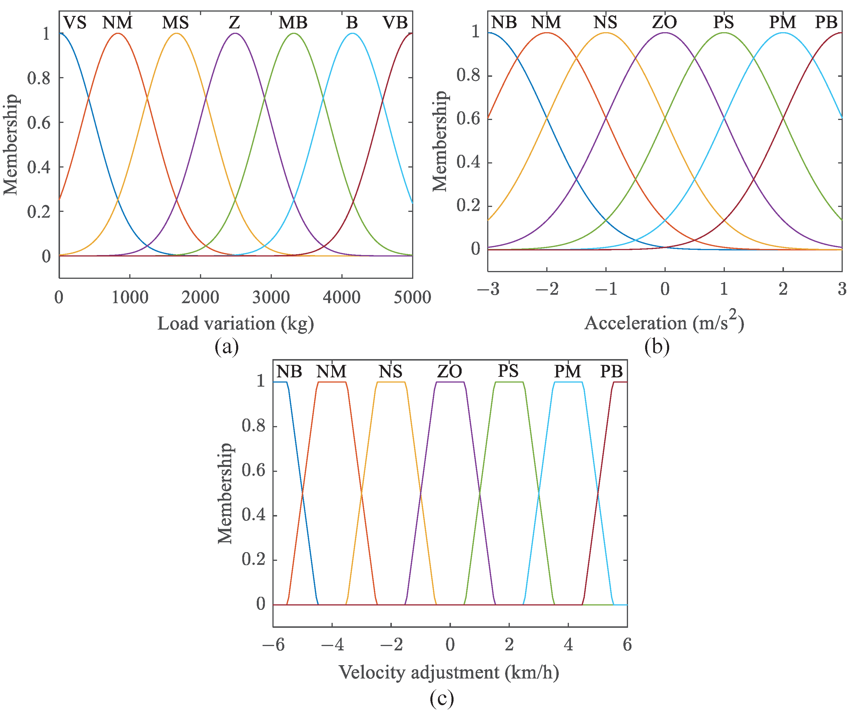
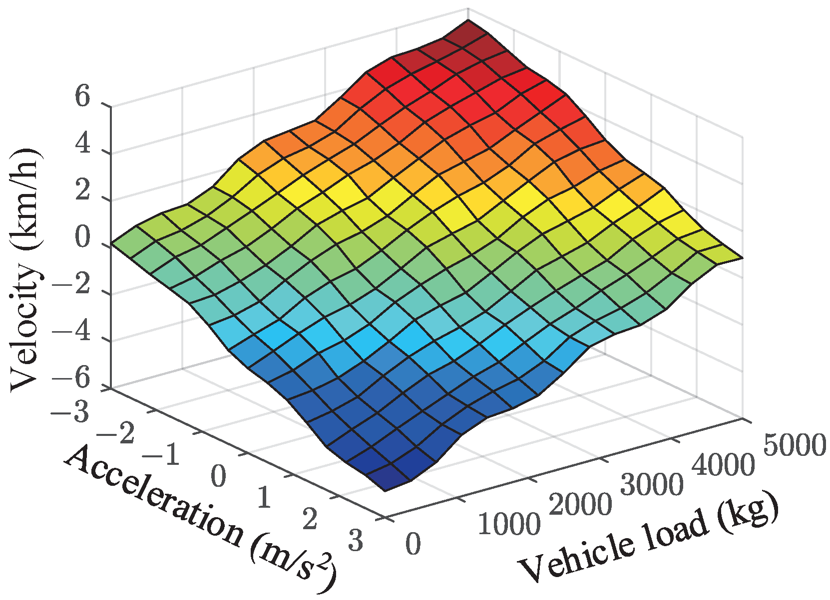
Generally speaking, optimization-based and learning-based methodologies in gear shift optimization still have a limitation in practical application. Three main issues must be overcome to realize online gearshifts whilst ensuring the vehicle’s overall performance. First, although the driving conditions can be obtained based on forecasting or V2I technical, some stochastic conditions (e.g., driving style or random loading) in vehicle operation are hard to make explicit. This will significantly impact the robustness of the formulated shift schedule. Second, the shift delay time between adjacent gears is not considered, which may lead to an unexpected frequent gear shift during the optimization. Third, a specific shift schedule with a straightforward control strategy should be more appropriate than a complicated algorithm considering a vehicle processor’s computing limits and costs. Inspired by [42,43], a Fuzzy logical-based controller was designed, considering the variation in the vehicle load and acceleration to regulate the gear shift velocity of a predesigned shift map online, which was extracted from the offline DP solution to promote the comprehensive performance of the vehicle in practice.
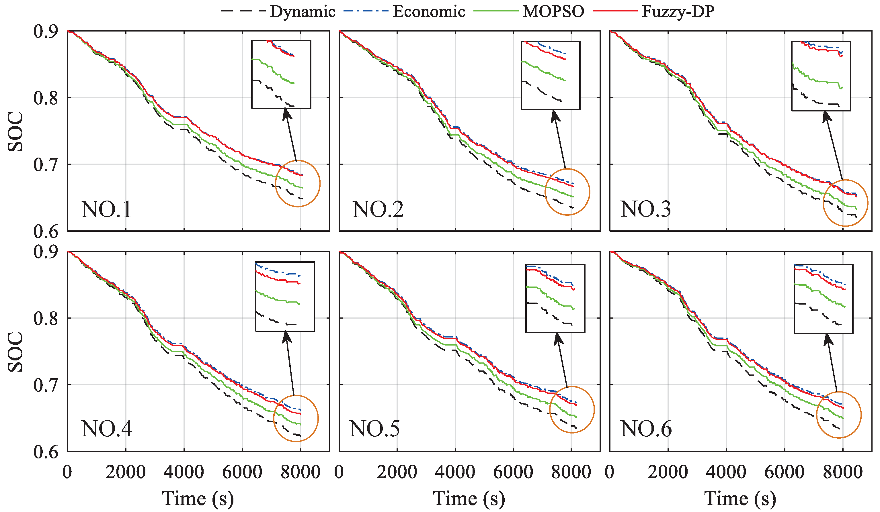
The main innovation and contribution are summarized as follows. (1) An adaptive shift schedule design framework is formulated based on DP and fuzzy logical control to promote the comprehensive abilities of the multi-gear AMT electric vehicles. (2) Abundant typical driving cycles are employed to calculate the optimal working points of the vehicle based on DP, whilst an offline optimal shift schedule is derived according to the optimization results. (3) A fuzzy logical controller is designed with the variation in the vehicle load and acceleration, which are considered as input to adjust the gear shift velocity online. (4) Three benchmark shift schedules, including dynamic-oriented, economic-oriented and MOPSO schedules, are constructed to evaluate the effectiveness of the proposed shift schedule, and the results indicate the superior performance of the proposed Fuzzy-DP method in terms of the dynamics, economy, and shift frequency.
The remainder of the paper is organized as follows. Section 2 presents the studied multi-gear AMT powertrain models and vehicle dynamic models. In Section 3, three benchmark shift schedules are formulated: dynamic-oriented, economic-oriented, and MOPSO schedules. The adaptive shift schedule design architecture is formulated in Section 4, where the DP is adopted to derive an offline optimal shift schedule, and an online Fuzzy logical controller is designed for shift velocity adjustments. Section 5 exhibits the validation results of the proposed method in terms of dynamics, economy, and shift frequency. Finally, core conclusions are summarized in Section 6.

2. Modeling of Powertrain

2.1. Configuration of the Electric Vehicle

The powertrain of a multi-gear AMT electric vehicle is usually composed of electric motors, automated manual transmission (AMT), and power batteries. The modeling quality of these components has a significant impact on the performance of the shift schedule. Hence, the numerical models of the critical components are established according to the studied electric vehicle.
As shown in Figure 1, the motor and the AMT are directly connected to constitute the drive system. The power battery can provide both the driving and braking energy while the motor is working as a drive motor or a generator, respectively. The main parameters of the multi-gear AMT electric vehicle are listed in Table 1.

2.2. Powertrain Models

A permanent magnet synchronous motor with a peak power of 90 kW is used in the electric vehicle, whilst a steady-state numerical efficiency model of the electric motor is utilized to calculate the motor’s power. Since the motor’s efficiency is considered to be the same when the torque of the motor is defined as positive and negative, the electric motor’s power can be expressed as follows [4].
P m = T m · n m · η m s g n ( T m ) 9550 ,
where P m represents the power of the electric motor. T m and n m represent the torque and rational speed of the electric motor, respectively. η m is the mapping relationship of the motor efficiency, which can be interpolated by the motor’s torque and rational speed, as shown in Figure 2. Then, the efficiency of the electric motor is expressed as follows.
η m = η m ( n m , T m ) .
Moreover, s g n ( · ) is a sign function that can be defined as follows.
sgn ( T m ) = 1 , i f T m 0 1 , o t h e r w i s e .
A 4-speed AMT is utilized to downsize the motor’s output torque and improve the motor’s work zone by adjusting the rotational speed and torque. Thus, the AMT model is expressed as follows.
T b = T m · i g ( n ) · η g ( n ) n b = n m / i g ( n ) ,
where T b and n b represent the AMT’s output torque and output rational speed, respectively. i g ( n ) denotes the speed ratio of the AMT for the n t h gear. η g ( n ) is the AMT efficiency for the n t h gear, which can be obtained from a bench test. The AMT efficiency is shown in Figure 3.
The lithium iron phosphate battery pack is employed for the studied electric vehicle, and its nominal capacity and rated voltage are 200 A·h and 354 V, respectively. The battery is simplified as the equivalent circuit based on the internal resistance model, and the open circuit voltage and the internal resistance can be considered as the function of the battery state-of-charge (SOC), as shown in Figure 4. Therefore, the relationship between the open circuit voltage, battery power, and battery current is described as follows [4,41].
P b a t t = U o c ( S O C ) · I I 2 · R 0 ( S O C ) ,
where P b a t t denotes battery power. U o c , I, and R 0 denote the open circuit voltage, the battery current, and the internal resistance, respectively.
According to the solution of Equation (5) for the current I, the variation in the battery SOC can be calculated, and the dynamics of the battery pack can be described as follows [4,7].
I = U o c ( S O C ) U o c ( S O C ) 2 4 · P b a t t R 0 ( S O C ) 2 R 0 ( S O C ) S O ˙ C = I Q b a t t = f ( S O C , P b a t t ) ,
where S O ˙ C represents the changing of the battery SOC. Q b a t t is the nominal capacity of the battery.

2.3. Vehicle Dynamic Model

The longitudinal dynamic model is usually simplified as a point-mass model, neglecting the impact of the lateral dynamics and vertical dynamics on the vehicle. The simplified model is expressed as follows [4,41].
M · d u d t = T r r w h 1 2 C d A ρ d u 2 M g ( f r cos θ + sin θ ) T r = T m · i g · i 0 · η T + T b r k ,
where M is the gross mass of the vehicle, composed of the curb mass and vehicle load. T r , r w h , C d , A, ρ d , and u denote the required torque, wheel radius, air drag coefficient, front area, air density, and vehicle velocity, respectively. g, f r , θ , and η T represent the gravity acceleration, rolling resistance coefficient, road slope, and transmission efficiency. T b r k means the mechanic braking torque provided by conventional friction brakes when regenerative braking is insufficient to ensure the desired braking torque. The mechanical braking torque T b r k can be described as follows.
T b r k = 0 T b r q T g _ max T b r q T g _ max T b r q > T g _ max ,
where T b r q is the required braking torque for vehicle. T g _ max represents the maximum regenerative braking torque provided by the electric motor.

3. Benchmark Shift Schedule Design

The conventional shift schedule can be divided into a dynamic-oriented shift schedule, as well as an economic-oriented shift schedule. The former ensures the vehicle has a more robust dynamic performance, while the latter provides lower energy consumption. Furthermore, a comprehensive shift schedule based on multi-objective particle swarm optimization (MOPSO) is also established to verify the effectiveness of the proposed adaptive shift schedule.

3.1. Dynamic-Oriented Shift Schedule

To ensure the vehicle’s dynamic performance, the intersection of the acceleration curves for the adjacent gear corresponding to the same accelerator pedal opening is selected as the best shift point of the dynamic-oriented shift schedule. The acceleration of the vehicle can be expressed as [9]:
d u d t = 1 δ M T m i g i 0 η T r w h M g f r cos θ 1 2 C d A ρ d u 2 .
It should be noted that if there is no intersection between the adjacent gear, the gear corresponding to the higher velocity should be considered the shift point. As shown in Figure 5a, a shifting curve for the dynamic-oriented shift schedule can be extracted by fitting the points into a curve when the intersection of the acceleration curves for different accelerator pedal openings are collected. Furthermore, the upshift and downshift points need to be different to avoid frequent shifting, where a velocity difference of about 5∼8 km/h is always set between the upshift and downshift points [9], as shown in Figure 5b.

3.2. Economic-Oriented Shift Schedule

To ensure the vehicle’s economic performance, the intersection of the electric motor efficiency of adjacent gears corresponding to the same accelerator pedal opening is selected as the best shift point. According to Equation (2), the electric motor efficiency can also be expressed as a function of vehicle velocity and motor torque [9]:
η m = f ( i g i 0 u 0.377 r w h , T m ) .
Then, the upshift curve can finally be obtained by fitting the intersection under different accelerator pedal openings. In other words, the economic-oriented upshift curve can also be obtained by taking the efficiency surface’s crossover line of the motor at the adjacent gear position, as shown in Figure 6a. Like the dynamic-oriented shift schedule, the velocity difference must also be set to avoid undesired frequent shifting for the economic-oriented shift schedule, as depicted in Figure 6b.

3.3. MOPSO Shift Schedule

There is a contradiction between dynamic-oriented and economic-oriented shift schedules. The former requires the vehicle to shift as late as possible, while the latter is the opposite. It is necessary to consider the impact of shifting point velocity on both of them to ensure a better vehicle performance. Therefore, a multi-objective particle swarm optimization (MOPSO) algorithm is employed to optimize the shift schedule to acquire a comprehensive shift schedule.
In this problem, the objective function is composed of dynamic and economic objectives, where the velocity of the upshift points is considered a design variable. It can be described as follows.
min F ( [ u 1 , u 2 , u 3 ] ) = ( f 1 , f 2 ) T .
The dynamic objective is determined based on the acceleration time (i.e., the time for the vehicle to accelerate from zero to a target speed) [21]. It can be calculated by the following equations.
f 1 = 1 3.6 0 u 1 δ 1 M T m i g i 0 η T r w h M g f r cos θ 1 2 C d A ρ d u 2 · d u + 1 3.6 u 1 u 2 δ 2 M T m i g i 0 η T r w h M g f r cos θ 1 2 C d A ρ d u 2 · d u + 1 3.6 u 2 u 3 δ 3 M T m i g i 0 η T r w h M g f r cos θ 1 2 C d A ρ d u 2 · d u + 1 3.6 u 3 80 δ 4 M T m i g i 0 η T r w h M g f r cos θ 1 2 C d A ρ d u 2 · d u ,
where u 1 , u 2 , u 3 represent the velocity of the upshift points from 1st gear to 2nd gear, 2nd gear to 3rd gear, and 3rd gear to 4th gear corresponding to a specific accelerator pedal opening, respectively. δ 1 , δ 2 , δ 3 , δ 4 are the rotation mass coefficients for different gears. The target speed of the vehicle is designed as 80 km/h.
Accordingly, the vehicle’s energy consumption during the acceleration from 0 to 80 km/h is taken as an economic objective and described as follows.
f 2 = 0 t 1 P m η g · η T · d t + t 1 t 2 P m η g · η T · d t + t 2 t 3 P m η g · η T · d t + t 3 t 4 P m η g · η T · d t ,
where t 1 , t 2 and t 3 represent the vehicle running time during the 1st gear, 2nd gear, and 3rd gear, respectively. t 4 is the total time during vehicle acceleration. Moreover, the upshift velocity is respectively constrained within a scope based on dynamic-oriented and economic-oriented shift schedules at the same acceleration pedal opening to improve the optimization efficiency of the MOPSO. This can be expressed as follows.
s . t . min u d 1 , u e 1 u 1 max u d 1 , u e 1 min u d 2 , u e 2 u 2 max u d 2 , u e 2 min u d 3 , u e 3 u 3 max u d 3 , u e 3 ,
where u d 1 , u d 2 , u d 3 represent the upshift velocity of the dynamic-oriented shift schedule for 1st to 2nd gear, 2nd to 3rd gear and 3rd to 4th gear, respectively. u e 1 , u e 2 , u e 3 represent the upshift velocity of the economic-oriented shift schedule for 1st to 2nd gear, 2nd to 3rd gear and 3rd to 4th gear, respectively.
In the solving process, the maximum number of iterations is 500, and the particle swarm size is 100. Figure 7a gives the optimal solution and Pareto frontier when the accelerator pedal opening is 100%. To provide compromise between the dynamic and economic objectives, a linear weighting method is utilized to integrate two of them, which can be described as follows [21].
f = ω 1 s 1 · f 1 + ω 2 s 2 · f 2 ,
where ω 1 and ω 2 represent the weighting factor of the dynamic objective and economic objective. s 1 and s 2 are scale factors to balance the order of magnitude between the two objectives. When the linear objective is determined, the optimal particle (i.e., the optimal upshift velocity) can be obtained, as shown in Figure 7b.
Accordingly, the upshift velocity of the comprehensive shift schedule can be obtained by the MOPSO method when the accelerator pedal opening is set as 10%, 20%, 30%, 40%, 50%, 60%, 70%, 80%, 90%, and 100%, respectively.The results are listed in Table 2, and the downshift velocity can be obtained by setting a velocity difference similar to the previous method.

4. Adaptive Shift Schedule Design

Dynamic programming (DP) is considered one of the most popular methods to explore the global optimal solution for multistage decision-making problems while some necessary prior knowledge is known [7,21]. As the decision of the gear position can be regarded as a discrete-time dynamic optimization problem with a given driving cycle, DP is utilized to decide the optimal gear position based on a combined driving cycle in this paper. Although abundant historical driving cycles can be adopted to acquire the shift schedule based on DP, it cannot completely adapt to the complicated and changeable actual driving conditions, which may lead to an unexploited energy-saving potential in the multi-gear AMT electric vehicle. Hence, a fuzzy logical control method is utilized to adjust the shifting point of the DP-based shift schedule to promote adaptability to various driving cycles. Noting that the vehicle load and acceleration considerably impact the vehicle’s dynamics and economy; they are deployed as the fuzzy logical controller’s input. At the same time, the velocity of the shifting points will be dynamically adjusted by the fuzzy logical controller. This means that the vehicle load and acceleration are obtained in real-time, and the fuzzy logical controller will output a velocity increment (or reduction) to adjust the shift speed of the DP-based shift schedule corresponding to the real-time vehicle load and acceleration. The diagram of the adaptive shift schedule framework is shown in Figure 8.

4.1. Dynamic Programming Formulation

Considering the characteristics of the DP-solving process, the driving cycle needs to be discretized. Meanwhile, the vehicle powertrain model in Section 2 should also be described in a discrete recursion equation. Hence, the shift schedule optimization problem can be described as follows [7,21].
x ( k + 1 ) = f ( x ( k ) , u ( k ) ) x ( k ) = [ S O C ( k ) , g x ( k ) ] T u ( k ) = s h i f t ( k ) ,
where f ( · ) represent the state equation of the dynamic system. x ( k ) denotes the state vector of the vehicle, which is composed of the battery SOC and gear position. u ( k ) is the gear shift command s h i f t ( k ) containing upshift, downshift, and maintaining. k denotes the discrete-time sequence ( k = 0 , 1 , 2 , , N 1 ). Thus, the discrete state equation of the state variable can be expressed by the following equation [7,21].
S O C ( k + 1 ) = S O C ( k ) U o c ( k ) U o c 2 ( k ) 4 R 0 ( k ) P b a t ( k ) 2 R 0 ( k ) Q b a t ( k ) g x ( k + 1 ) = 1 4 g x ( k ) + s h i f t ( k ) g x ( k ) + s h i f t ( k ) < 1 g x ( k ) + s h i f t ( k ) > 4 o t h e r w i s e ,
where the control variable s h i f t ( k ) is described as:
s h i f t ( k ) = + 1 u p s h i f t 1 d o w n s h i f t 0 m a i n t a i n i n g .
The purpose of the optimization problem is to determine the optimal control variables to minimize the energy consumption of the vehicle. Thus, the cost function is expressed as [7]:
J = min k = 0 N 1 L ( x ( k ) , u ( k ) ) = min k = 0 N 1 ( P b a t t ( k ) + β · s h i f t ( k ) ) ,
where P b a t t ( k ) denotes the energy consumption of the vehicle at the k t h time step. In addition, a penalty function β s h i f t ( k ) is also added to avoid the undesired frequent gearshift, whilst β is treated as a weighting factor.
In addition, some physical constrains are appended to guarantee the practical application, and the inequality constraints are expressed as follows.
s . t . P m _ min ( k ) P m ( k ) P m _ max ( k ) n m _ min ( k ) n m ( k ) n m _ max ( k ) P b a t t _ min ( k ) P b a t t ( k ) P b a t t _ max ( k ) S O C min ( k ) S O C ( k ) S O C max ( k ) ,
where P m ( k ) and n m ( k ) represent the instantaneous power and rotation speed of the motor at the k t h step. They are respectively limited by their lower boundaries P m _ min ( k ) , n m _ min ( k ) , and the higher boundaries P m _ max ( k ) , n m _ max ( k ) . P b a t t ( k ) and S O C ( k ) represent the instantaneous power and SOC of the battery. The former is constrained by the lower boundary P b a t t _ min ( k ) and the higher boundary P b a t t _ max ( k ) . The latter is limited to the allowed range, with a scope from 0.3 to 0.9.
As shown in Figure 9, a combined driving cycle composed of WVUSUB, WVUINTER, WVUCITY, UK bus, UDDS, NYCC, New York bus, MANHATTAN, Art urban, and China city bus cycle (CCBC) is employed to acquire the optimal working points of the AMT EV to formulate a DP-based shift schedule according to the global optimal solution.
Figure 10a depicts the DP solution’s gear position and battery SOC. It can be seen that the gear changes from 1st to 4th, which is consistent with our predesigned state variable. Moreover, the battery SOC gradually declines from 0.9 to 0.319, for which the constraints of the battery SOC are also satisfactory. As shown in Figure 10b, a fragment including the desired power of the vehicle and the battery power is extracted from the DP solution to examine the variation in battery power. This demonstrates that the output power of the battery can follow the vehicle demand power. The battery power is slightly larger than the vehicle demand power in the driving mode, while the recovered energy is less than the vehicle demand braking power.
In addition, Figure 11 depicts the optimal working points of AMT for various gear positions based on the DP solution. There are apparent boundaries between the working points of adjacent gears. Hence, an upshift curve can easily be picked up between them. In other words, a shift schedule based on DP results can be extracted and deployed as an online strategy for AMT control. Moreover, a downshift delay must also be designed within 5∼8 km/h to eliminate frequent gear-shifting.

4.2. Fuzzy Logic Controller Design

Fuzzy logic control is a robust control method that does not depend on mathematical models. It has been popularly applied to the control strategy of EVs as it can effectively solve the control problem of vehicles under complex working conditions [22,43]. This paper employs the fuzzy logical control method to adjust the velocity of the upshift points and the downshift points based on the DP-based schedule. The vehicle’s load variation and acceleration are input to the fuzzy logical controller. The velocity adjustment of the shifting points will be output from the fuzzy logical controller in real-time. Considering the actual operation of the vehicle, the acceleration a is designed for a scope of from −3 m/ s 2 to 3 m/ s 2 , load variation Δ m is within 0∼5000 kg, and the velocity adjustment Δ u is designed as ranging from −6 km/h to 6 km/h. Then, the load variation, acceleration, and velocity adjustment are converted into the discourse of the universe, which can be described as follows.
Δ m = { 0 , 1000 , 2000 , 3000 , 4000 , 5000 } a = 3 , 2 , 1 , 0 , 1 , 2 , 3 Δ u = { 6 , 5 , 4 , 3 , 2 , 1 , 0 , 1 , 2 , 3 , 4 , 5 , 6 } ,
where Δ m , a , and Δ u represent the universe of the load variation, acceleration, and velocity adjustment, respectively.
The fuzzy subset of the load variation is divided into VS, NS, MS, Z, MB, B, and VB, whilst acceleration is partitioned into NB, NM, NS, ZO, PS, PM, and PB. Meanwhile, the velocity adjustment is also divided into seven parts, including NB, NM, NS, ZO, PS, PM, and PB. Then, the Gaussian membership function is employed to describe the input variables of the fuzzy cotroller while the Trapezoidal membership function is employed to express the output variable. Therefore, the membership function of the load variation, acceleration, and velocity adjustment can be obtained, as shown in Figure 12.
In this study, the Mamdani model is utilized to formulate the control rules [43], where there are two fuzzy input variables, (i.e., load variation and acceleration), and each of them has seven subsets. Therefore, a total of 7 × 7 = 49 control rules can be acquired. Generally speaking, when the vehicle’s acceleration increases, it needs to be shifted into a higher gear. Thus, the fuzzy logical controller tends to output a negative velocity adjustment to promote the gear-upshift of the AMT. On the other hand, the demand for the vehicle’s dynamic performance will be preferred owing to the increasing vehicle load and a delayed upshift should be necessary. Therefore, a positive velocity adjustment will be output by the fuzzy logical controller to postpone the gear-upshift. Accordingly, the output of shift velocity adjustment means that the heavier the vehicle load, the larger the velocity adjustment, while the greater the acceleration, the smaller the velocity adjustment.
The centroid method is utilized to defuzzify the fuzzy inference result to obtain the exact output value [43]. Hence, the relationship between shift velocity adjustment and vehicle load and acceleration can be acquired, as shown in Figure 13. Finally, a fuzzy logical controller based on vehicle load and acceleration will be introduced to the DP-based shift schedule to constitute a Fuzzy-DP schedule, which can adjust the gearshift velocity online to improve the adaptation of the shift schedule to various driving conditions.

5. Validation and Discussion

5.1. Dynamic Performance

As acceleration time is usually applied to evaluate the vehicle’s dynamic performance, the studied EV’s acceleration time from 0 to 80 km/h is calculated when the accelerator pedal opening is 100%, based on the four shift schedules, i.e., dynamic, economic, MOPSO, and Fuzzy-DP schedules.
As shown in Figure 14a, there are apparent differences in the gear-shift time of the four shift schedules. Among them, the shift time of the economic schedule is the earliest, while the dynamic schedule is the latest. For the economic schedule, the AMT upshifts time from 1st to 2nd gear, from 2nd to 3rd gear, and from 3rd to 4th gear, respectively, at 2.9 s, 4.9 s, and 8.2 s, compared to the 4.7 s, 10.9 s, and 27.0 s for the dynamic schedule. As the MOPSO and Fuzzy-DP consider the vehicle’s dynamics and economy, the upshift time is between the dynamic and economic schedules. In addition, the Fuzzy-DP considers the vehicle load variation and acceleration, so the gear-shift time is slightly later in contrast to the MOPSO. The time needed for the MOPSO and Fuzzy-DP to enter the 2nd gear only has a 0.1 s difference between them. The time for upshift into 3rd gear is 10.0 s and 10.7 s, respectively, while the time to move into 4th gear is 18.5 s and 21.4 s. The results reveal a slight difference in the switching time of the 3rd gear, while there is a significant difference in the switching time of the 4th gear.
The earlier upshift from low gear to high gear will inevitably lead to the unexpected loss of the vehicle’s dynamic performance. The results from Figure 14b reveal that the acceleration performance of the economic schedule is the worst, while the dynamic schedule is superior. The acceleration times of the MOPSO and Fuzzy-DP are within the results of the dynamic and economic schedules. Furthermore, the Fuzzy-DP is closer to the dynamic schedule because it thoroughly considers the changes in vehicle load and acceleration. Table 3 exhibits the vehicle’s acceleration and upshift times from low to high gear for different shift schedules. Fuzzy-DP shows an 8.86% decrease in acceleration time compared with the MOPSO, while having a 1.89% increase compared to the dynamic schedule. The results demonstrate the Fuzzy-DP schedule leads to a remarkable improvement in dynamic performance in contrast to the MOPSO.

5.2. Economic Performance

To validate the adaptability of the Fuzzy-DP, the economy of four shift schedules is compared based on the stochastic driving cycles. Figure 15 exhibits six groups of the stochastic driving cycles (i.e., NO.1∼NO.6), including velocity and vehicle load, which are implemented to evaluate the vehicle’s economic performance. Noting that the studied EV mainly operates in urban areas, the road slope is neglected, considering the actual characteristics of the roads. The velocity and vehicle load variation are acquired from actual measurements.
As the battery SOC considerably impacts the energy consumption of electric vehicles, Figure 16 exhibits the SOC trajectories of the four shift schedules under the aforementioned stochastic driving cycles. Since the battery is the only power source for the electric vehicle, the SOC trajectories are similar under various shift schedules. However, it can be seen that the SOC trajectory of the dynamic schedule decreases the fastest, while the economic schedule is slowest. The SOC trajectory of the MOPSO is between the dynamic and economic schedules, which will have a definite energy saving compared to the dynamic schedule. However, there is still an undesirable gap compared to the economic schedule. Fortunately, the SOC trajectory of the Fuzzy-DP is closer to the economic schedule when compared to MOPSO. For the NO.1 driving cycle, the SOC trajectory almost coincides with the economic schedule, significantly improving the vehicle’s economy. In addition, it is worth noting that the initial SOC has a negligible influence on the results, and can therefore be set at 0.9. As the vehicle’s driving range is 200 km, and the driving cycles implemented for verification are approximately 40 km, the terminal SOCs of the four schedules are almost located from 0.6 to 0.7.
The working points of the Fuzzy-DP and MOPSO are plotted in Figure 17 to analyze the energy-saving potential. Two shift schedules are executed under different driving cycles, and the results are compared. It can be seen that their working points are both concentrated in a specific zone. However, there is a significant difference between them. The operating points of the Fuzzy-DP are mainly distributed in the lower-speed area, while MOPSO has more working points distributed in the higher-speed zone, which may lead to lower motor efficiency.
For further explanation, the frequency of the working points in a highly efficient zone is calculated and compared, as illustrated in Table 4. The statistic is focused on the ratio of the working points within the efficient area of 92% to all operating points during the trip. Thus, this can more intuitively reflect the energy-saving potential of the shift schedule. The results indicate that more working points are located in the highly efficient area for the Fuzzy-DP compared to the MOPSO. Although there are specific differences in different driving cycles, Fuzzy-DP has preferable adaptability to various driving cycles. It has more energy-saving potential than MOPSO, and the improvement of highly efficient zone working points can reach up to 4.02% in the NO.1 driving cycle.
The comparisons of the energy consumption for different driving cycles are represented in Figure 18.
The results based on the dynamic, economic, and MOPSO schedules are deployed as the benchmark to evaluate the effectiveness of the Fuzzy-DP. Not surprisingly, the dynamic schedule has the highest energy consumption, and the economic schedule is the most energy-efficient. Because the dynamic schedule can evidently improve a vehicle’s dynamics, it will sacrifice some economy, while the economic schedule is exactly the opposite. Although the MOPSO has a superior economic performance compared to the dynamic schedule, it still has significant potential for improvement. It is worth noting that the Fuzzy-DP can successfully guarantee the vehicle’s economy for various driving cycles, until it is almost close to the economic schedule for some driving cycles. This means that the proposed method can promote the shift schedule’s adaptability to stochastic driving cycles in a real-time application. The energy consumption of different shift schedules is listed in Table 5.
Specifically, the maximum energy-saving potential can be improved to 10.12% in contrast to the MOPSO, whilst the minimum is also promoted by 6.55%. Unfortunately, it still has a slight deficiency compared with the economic schedule. The energy consumption is 2.04% higher than the economic schedule in the NO.3 driving cycle. However, it is only 0.33% higher than the economic schedule in the NO.1 driving cycle. Overall, the proposed Fuzzy-DP schedule can significantly promote the adaptation to various driving cycles, leading to a desirable improvement in energy savings.

5.3. Shift Frequency

In addition, the shift frequency is also calculated and analyzed as it has a non-negligible influence on AMT service life. As shown in Figure 19, the economic schedule’s shift frequency is much higher than others, while the dynamic schedule is the lowest. The economic shift schedule has desirable economics, but the gear shift will be too frequent. The dynamic shift schedule is precisely the contrary. Fortunately, the MOPSO and the Fuzzy-DP are distinctly lower than the economic schedule and slightly higher than the dynamic schedule.
The shift frequency based on the four shift schedules under different driving cycles is listed in Table 6. It can be seen that the improvement in the shift frequency for Fuzzy-DP is remarkable compared with the economic schedule, where the maximum can reach up to 45.03%, i.e., the shift frequency is decreased from 866 to 476. As the shift frequency of the economic schedule for the NO.3 driving cycle is much lower than others, the promotion is only 18.67%, which is much more distinct and lower than other driving cycles. However, the effectiveness of the Fuzzy-DP is also noteworthy. There has been a considerable promotion of Fuzzy-DP compared to the MOPSO, where the shift frequency can be reduced from 549 to 502, with an improvement of 8.56% (in the NO.4). Furthermore, the improvement is also significant under other driving cycles.

6. Conclusions

This paper presents an adaptive shift schedule design methodology based on DP and fuzzy logical control to promote the shift schedule’s adaptability, thereby improving the comprehensive performance of multi-gear AMT electric vehicles in real-time implementation. A DP algorithm is employed to extract a globally optimal shift schedule based on a combined driving condition containing 11 groups of typical driving cycles. To improve the adaptability of the DP-based shift schedule, the vehicle load variation and acceleration are introduced to the fuzzy logical controller, whilst the velocity adjustment is output to regulate the gear-shift velocity in real-time.
The dynamic, economic, and MOPSO shift schedules are also constructed as the benchmark to evaluate the performance of the proposed shift schedule. The results demonstrate that the Fuzzy-DP has considerable advantaes in promoting the vehicle’s dynamic performance compared with MOPSO. The acceleration time from 0 to 80 km/h can be improved by 10.83%. Additionally, the proposed shift schedule also leads to expected impromvements in energy-saving, where the highest improvements can reach up to 10.12% in contrast to MOPSO. In some driving cycles, the energy-saving potential is quite close to the economic schedule, where the energy consumption is only 0.33% higher than the economic schedule. Moreover, the proposed shift schedule can effectively inhibit frequent shifting to increase the service life of the AMT.
In the future, a test bench should be established to further evaluate our proposed method for real-time implementation. Moreover, an electro-thermal-aging coupled battery model and the information based on V2I and V2V can be introduced to our research to further improve the practicability of the Fuzzy-DP shift schedule.

Author Contributions

Conceptualization, X.L. and J.M.; methodology, X.L. and J.D.; software, X.C. and Y.Z.; validation, X.L., X.C. and J.D.; writing—original draft preparation, X.L. and J.D.; writing—review and editing, X.L. and J.M. All authors have read and agreed to the published version of the manuscript.

Funding

This research was supported by the Doctoral Scientific Research Foundation of Liaocheng University (grant number: 318052058); Natural Science Foundation of Shandong Province (grant number: ZR2020ME113); Fundamental Research Funds for the Central Universities, CHD (grant number: 300102221503/K21LC0301).

Institutional Review Board Statement

Not applicable.

Informed Consent Statement

Not applicable.

Data Availability Statement

The data in this paper are from actual road conditions, provoided by a vehicle enterprise and involve a confidentiality agreement. The dataset in this paper is not publicly available.

Conflicts of Interest

The authors declare no conflict of interest.

Abbreviations

The following abbreviations are used in this manuscript:
DPDynamic Programming
AMTAutomated Manual Transmission
MOPSOMulti-objective Particle Swarm Optimization
EVsElectric Vehicles
GAGenetic Algorithm
NSGA-IINon-dominated Sorting Genetic Algorithm II
PMPPontryain’s Minimum Principle
MPCModel Predictive Control
RLReinforcement Learning
V2VVehicle-to-Vehicle
V2IVehicle-to-Infrastructure
SOCState-of-Charge

References

  1. Saha, A.; Simic, V.; Senapati, T.; Dabic-Miletic, S.; Ala, A. A dual hesitant fuzzy sets-based methodology for advantage prioritization of zero-emission last-mile delivery solutions for sustainable city logistics. IEEE Trans. Fuzzy Syst. 2022, 31, 407–420. [Google Scholar] [CrossRef]
  2. Wang, L.; Ma, J.; Zhao, X.; Li, X.; Zhang, K.; Jiao, Z. Adaptive robust unscented Kalman filter-based state-of-charge estimation for lithium-ion batteries with multi-parameter updating. Electrochim. Acta 2022, 426, 140760. [Google Scholar] [CrossRef]
  3. Liu, Y.; Fang, Z.; Cheung, M.H.; Cai, W.; Huang, J. An incentive mechanism for sustainable blockchain storage. IEEE-ACM Trans. Netw. 2022, 30, 2131–2144. [Google Scholar] [CrossRef]
  4. Liu, X.; Guo, H.; Du, J.; Zhao, X. A modified model-free-adaptive-control-based real-time energy management strategy for plug-in hybrid electric vehicle. Energy Sci. Eng. 2022, 10, 4007–4024. [Google Scholar] [CrossRef]
  5. Li, X.; Ma, J.; Zhao, X.; Wang, L. Study on Braking Energy Recovery Control Strategy for Four-Axle Battery Electric Heavy-Duty Trucks. Int. J. Energy Res. 2023, 2023, 1868528. [Google Scholar] [CrossRef]
  6. Gao, B.; Yue, H.; Chen, H. Multi-speed torque coupler of hybrid electric vehicle to exploit energy reduction potential. Int. J. Veh. Des. 2015, 69, 255–272. [Google Scholar] [CrossRef]
  7. Lin, C.; Zhao, M.; Pan, H.; Yi, J. Blending gear shift strategy design and comparison study for a battery electric city bus with AMT. Energy 2019, 185, 1–14. [Google Scholar] [CrossRef]
  8. Wang, Y.; Wu, J.; Zhang, N.; Mo, W. Dynamics modeling and shift control of a novel spring-based synchronizer for electric vehicles. Mech. Mach. Theory 2022, 168, 104586. [Google Scholar] [CrossRef]
  9. Lin, X.; Li, Y.; Xia, B. An online driver behavior adaptive shift strategy for two-speed AMT electric vehicle based on dynamic corrected factor. Sustain. Energy Technol. Assess. 2021, 48, 101598. [Google Scholar] [CrossRef]
  10. Peng, J.; Zhang, H.; Li, H.; Jiang, Y.; Li, Z. Multi-parameter predictive shift schedule of automatic mechanical transmission for electric bus. Proc. Inst. Mech. Eng. Part D-J. Automob. Eng. 2022, 236, 2138–2152. [Google Scholar] [CrossRef]
  11. Shen, W.; Yu, H.; Hu, Y.; Xi, J. Optimization of shift schedule for hybrid electric vehicle with automated manual transmission. Energies 2016, 9, 220. [Google Scholar] [CrossRef]
  12. Roozegar, M.; Angeles, J. The optimal gear-shifting for a multi-speed transmission system for electric vehicles. Mech. Mach. Theory 2017, 116, 1–13. [Google Scholar] [CrossRef]
  13. Ngo, V.; Hofman, T.; Steinbuch, M.; Serrarens, A. Optimal control of the gearshift command for hybrid electric vehicles. IEEE Trans. Veh. Technol. 2012, 61, 3531–3543. [Google Scholar] [CrossRef]
  14. Zhu, B.; Zhang, N.; Walker, P.; Zhou, X.; Zhan, W.; Wei, Y.; Ke, N. Gear shift schedule design for multi-speed pure electric vehicles. Proc. Inst. Mech. Eng. Part D-J. Automob. Eng. 2015, 229, 70–82. [Google Scholar] [CrossRef]
  15. Lei, Z.; Sun, D.; Liu, Y.; Qin, D.; Zhang, Y.; Yang, Y.; Chen, L. Analysis and coordinated control of mode transition and shifting for a full hybrid electric vehicle based on dual clutch transmissions. Mech. Mach. Theory 2017, 114, 125–140. [Google Scholar] [CrossRef]
  16. Wang, J.; Liu, Y.; Liu, Q.; Xu, X. Power-based shift schedule for pure electric vehicle with a two-speed automatic transmission. In IOP Conference Series: Materials Science and Engineering; IOP Publishing: Bristol, UK, 2016; Volume 157, p. 012016. [Google Scholar]
  17. Sun, G.B.; Chiu, Y.J.; Zuo, W.Y.; Zhou, S.; Gan, J.C.; Li, Y. Transmission ratio optimization of two-speed gearbox in battery electric passenger vehicles. Adv. Mech. Eng. 2021, 13, 16878140211022869. [Google Scholar] [CrossRef]
  18. Zhao, Z.; Chen, J.; Li, X.; Lei, D. Downshift decision and process optimal control of dual clutch transmission for hybrid electric vehicles under rapid braking condition. Mech. Syst. Signal Proc. 2019, 116, 943–962. [Google Scholar] [CrossRef]
  19. Zhang, B.; Zhang, J.; Shen, T. Optimal control design for comfortable-driving of hybrid electric vehicles in acceleration mode. Appl. Energy 2022, 305, 117885. [Google Scholar] [CrossRef]
  20. Silvas, E.; Hofman, T.; Murgovski, N.; Etman, L.P.; Steinbuch, M. Review of optimization strategies for system-level design in hybrid electric vehicles. IEEE Trans. Veh. Technol. 2017, 66, 57–70. [Google Scholar] [CrossRef]
  21. Liu, X.; Ma, J.; Zhao, X.; Zhang, Y.; Zhang, K.; He, Y. Integrated component optimization and energy management for plug-in hybrid electric buses. Processes 2019, 7, 477. [Google Scholar] [CrossRef]
  22. Gao, B.; Meng, D.; Shi, W.; Cai, W.; Dong, S.; Zhang, Y.; Chen, H. Topology optimization and the evolution trends of two-speed transmission of EVs. Renew. Sustain. Energy Rev. 2022, 161, 112390. [Google Scholar] [CrossRef]
  23. Montazeri-Gh, M.; Pourbafarani, Z. Simultaneous design of the gear ratio and gearshift strategy for a parallel hybrid electric vehicle equipped with AMT. Int. J. Veh. Des. 2012, 58, 291–306. [Google Scholar]
  24. Chen, S.Y.; Wu, C.H.; Hung, Y.H.; Chung, C.T. Optimal strategies of energy management integrated with transmission control for a hybrid electric vehicle using dynamic particle swarm optimization. Energy 2018, 160, 154–170. [Google Scholar] [CrossRef]
  25. Santiciolli, F.M.; dos Santos Costa, E.; Eckert, J.J.; Dionisio, H.J.; de Alkmin, L.C.; Dedini, F.G. Multiobjective gear shifting optimization considering a known driving cycle. Acta Sci.-Technol. 2015, 37, 361–369. [Google Scholar] [CrossRef]
  26. Wu, P.; Qiang, P.; Pan, T.; Zang, H. Multi-objective optimization of gear ratios of a seamless three-speed automated manual transmission for electric vehicles considering shift performance. Energies 2022, 15, 4149. [Google Scholar] [CrossRef]
  27. Liu, T.; Zou, Y.; Liu, D. Energy management for battery electric vehicle with automated mechanical transmission. Int. J. Veh. Des. 2016, 70, 98–112. [Google Scholar] [CrossRef]
  28. Gerdts, M. Solving mixed-integer optimal control problems by branch&bound: A case study from automobile test-driving with gear shift. Optim. Control Appl. Methods 2005, 26, 1–18. [Google Scholar]
  29. Xu, S.; Li, S.E.; Zhang, X.; Cheng, B.; Peng, H. Fuel-optimal cruising strategy for road vehicles with step-gear mechanical transmission. IEEE Trans. Intell. Transp. Syst. 2015, 16, 3496–3507. [Google Scholar] [CrossRef]
  30. Yuan, Z.; Teng, L.; Fengchun, S.; Peng, H. Comparative study of dynamic programming and Pontryagin’s minimum principle on energy management for a parallel hybrid electric vehicle. Energies 2013, 6, 2305–2318. [Google Scholar] [CrossRef]
  31. Ozatay, E.; Ozguner, U.; Filev, D. Velocity profile optimization of on road vehicles: Pontryagin’s Maximum Principle based approach. Control Eng. Pract. 2017, 61, 244–254. [Google Scholar] [CrossRef]
  32. Guo, L.; Gao, B.; Chen, H. Online shift schedule optimization of 2-speed electric vehicle using moving horizon strategy. IEEE-ASME Trans. Mechatron. 2016, 21, 2858–2869. [Google Scholar] [CrossRef]
  33. Ngo, V.D.; Colin Navarrete, J.A.; Hofman, T.; Steinbuch, M.; Serrarens, A. Optimal gear shift strategies for fuel economy and driveability. Proc. Inst. Mech. Eng. Part D-J. Automob. Eng. 2013, 227, 1398–1413. [Google Scholar] [CrossRef]
  34. Guo, L.; Gao, B.; Liu, Q.; Tang, J.; Chen, H. On-line optimal control of the gearshift command for multispeed electric vehicles. IEEE-ASME Trans. Mechatron. 2017, 22, 1519–1530. [Google Scholar]
  35. Li, G.; Görges, D.; Wang, M. Online optimization of gear shift and velocity for eco-driving using adaptive dynamic programming. IEEE T. Intell. Veh. 2021, 7, 123–132. [Google Scholar] [CrossRef]
  36. Xu, C.; Geyer, S.; Fathy, H.K. Formulation and comparison of two real-time predictive gear shift algorithms for connected/automated heavy-duty vehicles. IEEE Trans. Veh. Technol. 2019, 68, 7498–7510. [Google Scholar]
  37. Li, G.; Görges, D. Ecological adaptive cruise control for vehicles with step-gear transmission based on reinforcement learning. IEEE Trans. Intell. Transp. Syst. 2019, 21, 4895–4905. [Google Scholar] [CrossRef]
  38. Zhang, L.; Chen, F.; Ma, X.; Pan, X. Fuel economy in truck platooning: A literature overview and directions for future research. J. Adv. Transp. 2020, 2020, 2604012. [Google Scholar] [CrossRef]
  39. Han, J.; Vahidi, A.; Sciarretta, A. Fundamentals of energy efficient driving for combustion engine and electric vehicles: An optimal control perspective. Automatica 2019, 103, 558–572. [Google Scholar] [CrossRef]
  40. Han, K.; Li, N.; Kolmanovsky, I.; Girard, A.; Wang, Y.; Filev, D.; Dai, E. Hierarchical optimization of speed and gearshift control for battery electric vehicles using preview information. In Proceedings of the 2020 American Control Conference (ACC), Denver, CO, USA, 1–3 July 2020; pp. 4913–4919. [Google Scholar]
  41. Yang, C.; Li, L.; You, S.; Yan, B.; Du, X. Cloud computing-based energy optimization control framework for plug-in hybrid electric bus. Energy 2017, 125, 11–26. [Google Scholar] [CrossRef]
  42. Eckert, J.J.; Santiciolli, F.M.; Yamashita, R.Y.; Corrêa, F.C.; Silva, L.C.; Dedini, F.G. Fuzzy gear shifting control optimisation to improve vehicle performance, fuel consumption and engine emissions. IET Control Theory Appl. 2019, 13, 2658–2669. [Google Scholar] [CrossRef]
  43. Ma, N.; Hou, B.; Wang, Y.; Ren, K.; Chen, S.; Wang, P.; Lin, R.; Ji, J.; Ji, Y.; Han, Z.; et al. Research on Optimal Shift Control. J. Phys. Conf. Ser. 2020, 1575, 012116. [Google Scholar]
Figure 1. Configuration of the electric vehicle powertrain.
Machines 11 00915 g001
Figure 2. Efficiency of the motor.
Machines 11 00915 g002
Figure 3. Efficiency of the AMT.
Machines 11 00915 g003
Figure 4. (a) Internal resistance; (b) open circuit voltage.
Machines 11 00915 g004
Figure 5. (a) Acceleration of different pedal openings; (b) dynamic shift schedule.
Machines 11 00915 g005
Figure 6. (a) Motor efficiency surface for different gears; (b) economic shift schedule.
Machines 11 00915 g006
Figure 7. (a) Pareto solution of optimization objective; (b) particle swarm and optimal solution.
Machines 11 00915 g007
Figure 8. Adaptive shift schedule based on DP and fuzzy logical control.
Machines 11 00915 g008
Figure 9. Combined driving cycle.
Machines 11 00915 g009
Figure 10. (a) Gear position and battery SOC; (b) desired power and battery power.
Machines 11 00915 g010
Figure 11. Optimal working points of different gear.
Machines 11 00915 g011
Figure 12. (a) Load variation membership; (b) acceleration membership; (c) velocity adjustment membership.
Machines 11 00915 g012
Figure 13. Fuzzy logical rules of shift velocity adjustment.
Machines 11 00915 g013
Figure 14. (a) Shift time of different schedules; (b) acceleration time of different schedules.
Machines 11 00915 g014
Figure 15. Stochastic driving cycles for validation.
Machines 11 00915 g015
Figure 16. Comparisons of the battery SOC.
Machines 11 00915 g016
Figure 17. Comparisons of the motor working points.
Machines 11 00915 g017
Figure 18. Energy consumption of different schedules.
Machines 11 00915 g018
Figure 19. Comparisons of shift frequency.
Machines 11 00915 g019
Table 1. Key parameters of the electric vehicle.
ComponentsDescriptions
VehicleCurb mass: 4015 kg, Gross mass: 9000 kg@Max
Front area: 4.76 m 2 , Tire rolling radius: 0.391 m, Air drag coefficient: 0.55
MotorPeak torque: 450 N·m, Peak power: 90 kW, Peak rational speed: 5400 rpm
AMT4-speed, Speed ratio: 5.66/3.11/1.67/1
Final driveSpeed ratio: 4.785
BatteryCapacity: 200 A·h, Rated voltage: 354 V
Table 2. Upshift velocity of the MOPSO shift schedule.
Pedal Openings10%20%30%40%50%60%70%80%90%100%
u 1 (km/h)12131317191919191718
u 2 (km/h)19172330353532343330
u 3 (km/h)35284357555658565755
Table 3. Acceleration performance.
ShiftShift Time (s)Acceleration TimeComparisonImprovement
Schedules1st to 2nd2nd to 3rd3rd to 4th0∼80 km/h (s)Fuzzy-DP vs. DynamicFuzzy-DP vs. MOPSO
Dynamic4.710.927.021.2−1.89%8.86%
Economic2.94.98.225.0
MOPSO4.610.018.523.7
Fuzzy-DP4.710.721.421.6
Table 4. Percentages of motor working points in highly efficient zone.
ItemsPercentages of Motor Working Points @ ≥92% (%)
NO.1NO.2NO.3NO.4NO.5NO.6
MOPSO36.3836.3839.5443.7839.9541.58
Fuzzy-DP40.4039.8841.3245.0342.3443.10
Improvement4.023.501.781.252.391.52
Table 5. Results and comparisons of energy consumption.
Driving CyclesShiftTerminalEnergyComparisonsImprovements
SchedulesSOCsConsumptions (kW·h)Fuzzy-DP vs. EconomicFuzzy-DP vs. MOPSO
NO.1Dynamic0.648720.90−0.33%8.24%
Economic0.684817.98
MOPSO0.664819.66
Fuzzy-DP0.683618.04
NO.2Dynamic0.635121.43−1.57%6.55%
Economic0.671418.53
MOPSO0.651520.14
Fuzzy-DP0.667218.82
NO.3Dynamic0.621524.08−0.70%7.06%
Economic0.654321.31
MOPSO0.633923.09
Fuzzy-DP0.652221.46
NO.4Dynamic0.662323.65−2.04%10.12%
Economic0.623420.54
MOPSO0.656223.32
Fuzzy-DP0.640620.96
NO.5Dynamic0.635822.54−1.07%7.39%
Economic0.673719.58
MOPSO0.670021.37
Fuzzy-DP0.651919.79
NO.6Dynamic0.631622.54−1.33%6.87%
Economic0.669619.52
MOPSO0.649921.24
Fuzzy-DP0.665419.78
Table 6. Results and comparisons of shift frequency.
DrivingShiftShift FrequencyImprovements
CyclesSchedules(Times)Fuzzy-DP vs. EconomicFuzzy-DP vs. MOPSO
NO.1Dynamic31643.06%3.15%
Economic864
MOPSO508
Fuzzy-DP492
NO.2Dynamic33445.03%8.11%
Economic866
MOPSO518
Fuzzy-DP476
NO.3Dynamic36018.67%7.05%
Economic616
MOPSO539
Fuzzy-DP501
NO.4Dynamic35240.66%8.56%
Economic846
MOPSO549
Fuzzy-DP502
NO.5Dynamic36839.88%3.42%
Economic845
MOPSO526
Fuzzy-DP508
NO.6Dynamic36142.69%6.04%
Economic869
MOPSO530
Fuzzy-DP498
Disclaimer/Publisher’s Note: The statements, opinions and data contained in all publications are solely those of the individual author(s) and contributor(s) and not of MDPI and/or the editor(s). MDPI and/or the editor(s) disclaim responsibility for any injury to people or property resulting from any ideas, methods, instructions or products referred to in the content.

