
Analytic and Data-Driven Force Prediction for Vacuum-Based Granular Grippers

1
Institute of Machine Tools and Production Technology (IWF), Technische Universität Braunschweig, 38106 Braunschweig, Germany
2
Institute for Particle Technology (IPAT), Technische Universität Braunschweig, 38104 Braunschweig, Germany
*
Author to whom correspondence should be addressed.
Machines 2024, 12(1), 57; https://doi.org/10.3390/machines12010057
Submission received: 14 December 2023
/
Revised: 6 January 2024
/
Accepted: 10 January 2024
/
Published: 12 January 2024
(This article belongs to the Special Issue Intelligent Machine Tools and Manufacturing Technology)
Abstract
:As manufacturing and assembly processes continue to require more adaptable systems for automated handling, innovative solutions for universal gripping are emerging. These grasping systems can enable the handling of wide varieties of shapes, with gripping forces varying with grasped geometries. For the efficient usage of handling systems, precise offline and online prediction models for resulting grasping forces for different objects are necessary. In previous research, a flexible vacuum-based granular gripper was developed, for which no option for predicting gripping forces is currently available. Various gripping force prediction methodologies within the current state of the art are examined and evaluated. For an assessment of grasping forces of previously untested objects for the examined gripper with limited data and low computational effort, two methodologies are proposed. An analytical, 2D-geometry-derived gripper-specific metric for geometries is compared to a methodology based on similarities of objects to a small existing dataset. The applicability and prediction quality for different object types is analyzed through validation experiments. Gripping force estimations are possible with both methodologies, with individual weaknesses towards geometric features such as air permeabilities. With further development, robust predictions of gripping forces could be achieved for a wide range of unknown object geometries with limited experimental effort.
1. Introduction—Graspability Prediction
As a key component of technology for industrial manufacturing, grasping continues to be very relevant for the handling and assembly of components [1]. The productivity and quality of these manufacturing processes are very reliant on a precise and efficient grasp of components. In order to achieve a high degree of automation, secure and reliable gripping is necessary for the planning as well as the implementation of handling processes with minimal malfunctions or disturbances. Therefore, most industrial use cases currently emphasize the implementation of trusted standard gripping solutions such as suction cups or mechanical grippers. Innovative gripping solutions already offer advantages of coping more easily with the steadily increasing requirements for rising complexity, flexibility and product variants. However, for acceptance within the industry, it is necessary to enable reliable grasping planning and prediction for these new systems [2,3]. Additional factors such as a reduction in the over-dimensioning of gripper systems create advantages for grasping force assessments such as a decrease in required energy. This incentivizes the creation of methodologies for predicting and locating optimal gripping points on objects and components [4]. In conclusion, when new handling solutions are developed, their capabilities and possibly graspable object spectra have to be assessable. For this, methods for the evaluation of surfaces regarding their graspability and achievable gripping forces are a necessary hurdle-of-entry, especially regarding possible future industrial applicability.
In this research, different methods for the prediction of grasping forces for a specific innovative gripper are introduced and analyzed, especially for the goals of implementation with limited experimental effort and applicability during a gripping process in real-time. For this, the state of the art is shown in Section 1, with a differentiation between simulations, analytical parameters, feature-based prediction and similarity-based assessments of the grasping forces of different grippers. In Section 2.1, the specific gripper examined in this research is presented and the options regarding the possibilities for a prediction of achievable gripping forces are discussed. Previous applicable gripper-specific research, as well as reference object datasets, are discussed in Section 2.2, Section 2.3 and Section 2.4. The two selected prediction methodologies are shown in more detail in Section 3.1 and Section 3.2, with their results compared and analyzed in Section 3.3. The respective strengths and weaknesses for this gripper and the dataset are discussed in Section 4, with outlines for possible future continuations of these methods. The presented research is summarized in a conclusion in Section 5.
1.1. Graspability Prediction—Approaches and the State of the Art
According to Bohg et al. [5], the planning of grasps based on data given as 3D models such as point clouds is a widespread challenge that can be assessed with simulations as well as analytical and model-free approaches. This planning process mostly depends on the end effector used, as the characteristics and behavior can differ greatly. Due to the discussed current industrial focus on reliable handling systems, there is a plethora of graspability and gripping force prediction methods for widespread standard mechanical and vacuum-based grippers. However, the methods for graspability assessment for more flexible grippers are limited. There are few examples for research regarding the gripping characteristics in soft robotic designs, which are mostly focused on the applicability of an analytical assessment for pneumatic actuation in order to achieve curvature profiles for robotic hands with varying flexural rigidity [6]. Therefore, examples for various approaches mostly based on standard mechanical and vacuum-based grippers are examined in the following paragraphs in order to provide an overview of possible methods and approaches for the prediction of gripping behavior and achievable gripping forces. Finally, the possibility for similarity-based prediction as an overarching option for different grasping solutions is shown.
1.2. Simulations
Simulations theoretically enable the prediction of the behavior and achievable grasping forces for all types of grippers, including mechanical [7] or suction-based grippers, often implementing tools such as Finite Elements Modeling (FEM) [8,9]. Research on mechanical grippers usually analyses the specific mechanics of the contact of finger grippers with grasped objects [10,11,12], in order to determine the possible graspability based on forces created by friction or interlocking. Typically, simulations are adjusted specifically to the type of examined gripper, as the grasping characteristics differ greatly. Therefore, simulations of suction cup grippers, which are often made from silicone or other elastic materials, utilize simulation approaches optimized for these models, such as spring contact models and compliant contact models [13,14]. Even though simulations could achieve a highly accurate prediction of a resulting grasping force, they are usually not conducted ‘in real time’ during the online grasping process. This is a result of the simulation time possibly exceeding multiple hours or even days. Therefore, without significant reductions in complexity, simulations are mostly applicable to offline planning processes.
1.3. Gripper-Specific Analytical Parameters
Analytical parameters for a grasping force analysis specific to the boundary conditions of the handling task are widely used in research, such as quality criteria for the geometric analysis of achievable forces [15] for finger grippers. They are often specified as a singular quantitative value, which can be used to rank different grasping possibilities and ideally can be efficiently calculated from an object’s surface with limited computational effort. This could also be implemented online during the handling process in real-time in order to evaluate different objects for graspability. For this task, Jiang et al. [16] propose intuitive suction grasp analytic metrics based on point clouds for small suction grippers. These metrics could be based on physical properties such as the smoothness of a surface. These types of analytical parameters for grasping forces or graspability are often highly specific to the grippers’ functionality and therefore have to be developed and adjusted to the specific gripper characteristics. If the evaluation for this parameter is achievable with limited computational effort, a real-time assessment of object surfaces with a varying prediction accuracy will be enabled.
1.4. Model-Free Prediction and Machine Learning
A parameter for an assessment of a successful grasp or even a possible ranking of grasping locations could also be achieved through model-free implementations or Machine Learning (ML) methods such as Convolutional Neural Networks (CNN). An example is given in Lin et al. [17], where segmentation processing for mechanical grippers is applied. The researchers developed an ML-based methodology, which tries to fit shapes into object geometries in order to achieve a prediction of possible grippability, and validates this with an object set of 31 objects. Especially for suction-based gripping predictions, Deep Learning has been popular in past years. These approaches implement ML structures such as deep Grasp Quality CNNs [14,18,19], which require large amounts of data to create an accurate prediction of the gripping success. Combinations of multiple CNNs with the first ‘pruning unlikely candidate grasps’ and the second CNN used for the finer details have also been examined [20]. Additionally, CNNs are often used for the detection or determination of the orientation for known objects [21]. This can be categorized into the section of grasp hypotheses based on prior object knowledge [5], especially for the object recognition of known objects. This is often implemented with further CNN-based algorithms, such as YOLO or R-CNN [1,22]. Similar to most CNN-based algorithms, this requires a large amount of data in advance [18] or a continuous retraining, which would result in failures during operations [18]. Without these necessary data, the following lack of depth regarding the training of these algorithms usually impacts the effectiveness of these applications drastically.
1.5. Similarity-Based Prediction
Prediction based on similarity to known or familiar objects is quite common and can be performed by analytical methods. Compared to CNNs, this implementation can achieve a prediction with significantly reduced training data. Different methods for matching surfaces or point clouds [23] are possible. The usage of the Coherent Point Drift algorithm (CPD) has shown a broad spectrum of applications. This was first proposed by Myronenko and Song in 2010 [24] and can now be described as a well-known probabilistic framework which uses variational calculus on the basis of Gaussian mixture models for object comparison. CPD is applicable for both rigid as well as non-rigid applications in the presence of noise, outliers and missing points. This enables not only a prediction of the most optimal transformation for a best fit of two point clouds, but also a parameter for the similarity of two point clouds. This can be used to create a ‘score’ for the comparison of an object with an existing database. Its applicability to gripping strategies for different gripper types has already been shown [25,26] and is expected to be theoretically feasible for most grippers. The computational effort is dependent on the implemented calculus models as well as the size of the comparison dataset and could take from seconds up to hours to achieve an assessment of a single surface.
1.6. Summary of the State of the Art
In conclusion, simulations are generally feasible for the examination of the possible graspability of an object, but can be very resource-intensive depending on the gripper type. A feature-based and gripper-specific analytical parameter or a feature examination with a model-free approach (such as ML) would also be applicable. However, ML-based solutions tend to require large datasets. Lastly, predictions based on similarity to a known dataset could be achieved through ML or methods such as the CPD algorithm and are somewhat promising regarding their applicability towards new grippers. These possibilities should be evaluated for a possible implementation, especially regarding necessary boundary conditions resulting from a comparatively small amount of available data or a planned implementation in real-time for an online assessment during handling processes.
2. Materials and Methods
As an introduction to this section, the specific gripper examined is presented. In order to enable an overarching assessment of the applicability of the methods presented in the state of the art towards the specific examined gripper, a brief overview of existing insights into the behavior and characteristics is shown. This knowledge is applied to the selection process for appropriate methodologies to predict achievable grasping forces with this gripper and the set boundary conditions of a limited availability of experimental data and the goal of enabling online predictions. In order to enable the functionality of the selected methods with these set boundary conditions, two object datasets for the training and validation of these methods are discussed.
2.1. Examined Gripper
The examined gripping solution was developed at TU Braunschweig [27,28] and has opened up possibilities for the handling of a large variety of object geometries with a single gripper (see Figure 1). This gripper shows some similarities to granular grippers [29], the most characteristic difference being the porous area in the membrane. The gripper cushion can mold to different object geometries, creating a seal between the porous membrane area and the object (Figure 1b). When a pressure difference is applied to this setup, the granular material jams around the grasped object and the combined forces resulting from the pressure difference, as well as jamming effects, can achieve a secure grasp for a multitude of objects. However, due to the multitude of influences on the grasping process, from jamming to vacuum-based effects, the achievable grasping force varies for different object geometries (see Figure 2). This geometric dependency of the achievable grasping forces is addressed in this publication.
In order to improve the implementation of this new type of gripper in handling systems, which take advantage of the flexibility of this gripper, a prediction methodology specific to this new innovative system has to be created.
As seen in Figure 2, the knowledge of an object’s geometry can be used as an input parameter, which could be made available in online handling setups via various sensors or via CAD files during the planning in offline setups. However, due to the novelty of the gripper shown in Figure 1, there are currently no possible methodologies for predicting the resulting grasping forces for different geometries of handled objects. This grasping force therefore has to be evaluated through manual, time-consuming experiments for each individual new geometry.
In order to automate the assessment of differently shaped objects or object surface areas for a prediction of the resulting achievable grasping forces, an evaluation of possible methodologies is required. As discussed in Section 1, an implementation of such a method has to be selected and evaluated specifically with a focus on the requirements and boundary conditions of the examined gripper. The resulting output of such a methodology should enable a prediction for the expected resulting grasping force for any arbitrary surface with this new gripper.
2.2. Gripper-Specific Previous Research
Previous research has shown a dependency of this molding and jamming characteristic on gripping design parameters such as a membrane stiffnesses and granular materials [27]. Object surface roughness and materials have a negligible influence within a tested spectrum of materials [31]. For the following paragraphs, objects additively manufactured from PLA (Polyactic Acid) as well as a single gripper configuration with a height of 60 mm, a diameter of 150 mm and a filling of roughly 4100 ABS (Acrylonitrile-Butadiene-Styrene) beads with a diameter of 6 mm are examined (as seen in Figure 1). The membrane consists of 1.25 mm Polyurethane, and the symmetrically arranged porous area on the bottom of the gripper extends to a diameter of 95 mm and makes up a porous area Apor of about 4500 mm2. The forces in the Z-direction, as well as the vacuum during the gripping process, are shown in Figure 3. The contact of the gripper is achieved through an initial contact force surpassing a minimum (80 N for this research) by a Kuka LBR iiwa robot. The forces are measured with a K6D40 force sensor with a maximum force of 500 N in the Z-direction. The air pressure difference is measured by a VS VP8 SA M8-4 vacuum sensor and reaches up to 0.42 bar created by a Variair Unit SV201/2 (up to 4 kW), which is applied after opening the valve shown in Figure 1. After a delay of 2.5 s, the gripper is pulled up vertically at a defined pull-off-speed and detaches from the object surface. The maximum force measured during this process is used in the following paragraphs as the achievable gripping forces for an experiment. Further information about this setup can be found within the references [31,32].
As analyzed in Wacker et al. [31], this gripper’s characteristics are very comparable to a standard suction gripper for mostly flat surfaces. As long as over ~90% of the gripper’s porous membrane is covered by the object, the gripper can create a gripping force which can be described as being linear with the applied vacuum (see Equation (1)). However, for more complex geometries, the achievable gripping force Fachievable is also influenced by jamming as well as slip-off effects affecting the seal of the gripper with the object. The achievable gripping force continues to correlate with the applied vacuum Δp; however, an additional object-specific correction parameter Ccombined (Equation (1)) is utilized as well as the gripper-specific area Atmax.
Fachievable = Ccombined · Δp · Atmax
This correction parameter combines the influences of the affected area with the slip-off and granular jamming effects and can reach values between 0 and 1. Even for flat surfaces (with minimal influence from the granular jamming effects), a gripping force can be reached, which is higher than expected from the size of the porous area Apor and the standard relation of the pressure difference and the affected surface area. This is suggested to be a result of airflow effects and the curvature of the porous area (Figure 4a). The theoretical maximum gripping force would be achieved if the area of the entire diameter Atmax of the gripper arched inwards. In this case, no granular gripping effects (which are smaller than the suction effects) would influence the gripping force, and therefore this is the maximum achievable force and would be equal to the value 1. In this theoretical extreme, the gripper would be functioning as a suction cup and the actual effective area would be equal to Atmax.
A value for Ccombined close to zero can be achieved by trying to grasp an object with extreme geometries, where a limit of the gripper’s deformability is exceeded. This limit depends on factors such as the granular material or the membrane used. An example for the limited deformability towards objects is shown with a corrugated surface in Figure 4b. Visible is the CAD view of the geometry, as well as an image of the gripper being placed on top of the object, resulting in the described value for Ccombined close to zero.
This object-specific correction parameter Ccombined can currently only be determined through experiments or an approximation to available data. It shows a high accuracy to the linearization proven by a high coefficient of determination (R2) of up to 0.99 [31,32]. An example is shown for three different objects in Figure 5, where the achievable forces for the different objects are mostly linear with the pressure difference.
Here, the geometric dependency is visually perceptible as the parameter Ccombined, which can be described as the slope for individual objects (see also: Equation (1)).
The necessity for an experimental determination of Ccombined for every possible object is time-consuming. The experiments would have to be repeated for different configurations of this type of gripper, if, for example, a sturdier membrane has to be implemented due to requirements of a possibly rougher industrial environment. The capability of an offline prediction of a possible coverage of over 90% (as mentioned above) of the gripper’s porous surface as well as a prediction of Ccombined for unknown object geometries is a necessity for a preliminary assessment of a gripping possibility in order to achieve a certain reliability for handling processes. Therefore, the key questions for handling any new object surface with a specified gripper of this type have to be:
- Is the geometry grippable? (Is the object surface > 90% airtight?)
- Which Ccombined is achievable for this geometry?
In the future, this could be expanded for larger objects, in order to determine the optimal placement of the gripper for the highest possible grasping force or a minimal required vacuum.
2.3. Assessment and Selection of Possible Gripping Prediction Approaches for the Examined Gripper
According to the state of the art, a multitude of solutions for a prediction of Ccombined are possible (see Figure 6). A solution for the graspability prediction has to be chosen in accordance with the gripper’s design and the availability of data. Multiple combined approaches or multi-step solutions could also be a possibility. The main goal within this research is to determine and enable methods which allow for an assessment of achievable grasping forces for online as well as offline approaches with realistic experimental effort. Therefore, an analysis and selection of the possible approaches and their applicability with regard to experimental and computational effort are presented in the following paragraphs.
2.3.1. Applicability and Challenges of Simulations and Model-Free Approaches
As shown in Figure 6, simulations can be specifically adjusted to the design of the gripper. FEM models used for mechanical finger grippers are not easily transferrable to the characteristics of the examined gripper in this research. Similarly, the sealing of standard suction-based grippers is difficult to adjust to the characteristic interactions of deformability, granular contacts, sealing and suction, as well as to the larger scale of the examined gripper. In order to evaluate the jamming of particles with air flow, a simulation based on discrete elements (DEM) could also be examined. However, all of these simulations of this gripping design would be very resource-intensive. The achievable gripping force is influenced by a multitude of parameters. Possibly influential are the characteristics and the amount of granular material, the type and stiffness of the used membranes, etc., and these would have to be combined with a flow analysis (CFD) for an evaluation of the resulting grasping force. Therefore, even though simulations could achieve the most accurate predictions even with limited experimental validation, they are not part of the research discussed within this publication.
The current research for other types of grippers shows good results for CNN-based grasping predictions. However, this requires large amounts of either experimental or simulated data, which are not currently available for this gripper. Theoretically, all kinds of prediction methodologies could be simplified and approximated with ML-based methods, ranging from a similarity comparison to a simulative analysis. However, as none of these methodologies are currently available for the examined grasping solution, ML can be viewed merely as a possible aspect for future research regarding this gripper.
2.3.2. Selection of Prediction Methods Based on Similarity and Feature Extraction
As discussed above, solutions based on analytical parameters as well as similarity (Figure 6) could offer possibilities for a graspability assessment with limited computational or experimental effort, while still achieving adequate results. As a result, analytical parameters based on the geometry of grasped objects as well as a similarity to a pool of experimentally tested objects are the two approaches selected to enable a prediction of achievable grasping forces.
2.3.3. Structure and Further Procedure
Due to the analysis of the current state of the art, this research aimed to create specially developed analytical parameters based on the requirements of the examined gripper. As a comparison, a prediction of achievable gripping forces based on a similarity of geometric features achieved through CPD is implemented. Both methodologies are promising in regard to an implementation with limited experimental effort and are not directly dependent on Machine Learning implementations more complex than a simple regression. The approaches are examined regarding their respective strengths and weaknesses of achievable prediction quality as well as computational effort.
In order to enable this comparison of the suitability of the prediction methods for this gripper, sets of objects have to be specified which can be used to train and later validate and compare the prediction methods. As a basis for both methods, an adequate data structure for the object sets is defined which is used in the same format for both prediction methodologies. With these object datasets, as well as the defined data structure, the starting conditions for approaches are achieved and the description of the specific suggested procedures is presented in Section 3.1 and Section 3.2. In Section 3.3, results for both approaches are compared and possible further improvements are discussed in Section 4. A summary of this further structure is shown in Figure 7.
2.4. Examined Object Datasets
For both analytical as well as similarity-based predictions of gripping forces, experimental datasets consisting of different object geometries are necessary. As mentioned in Section 2.2, all used objects for both datasets are created from PLA in an additive manufacturing process, as surface parameters within specific limits have a negligible influence [31].
For the analyzed gripper, Wacker et al. [31] have shown a dependency of the graspability of an object on the creation of a vacuum, for which a good seal with the object surface is necessary. This graspability is mostly impacted by three object geometry characteristics:
Some other effects, such as slipping-off for more convex geometries or deformation of the membrane (as shown in Figure 4a), are also heavily influenced by the object geometries. When stable sealing is realized, the achievable gripping forces will most likely vary for different object shapes, even if they are of a similar size. This can be explained by suction- as well as non-suction-based grasping force components being influenced by granular jamming, slip-off and possible air-flow effects within the grasping interface. These additional forces vary in their strength with the geometrical features of the grasped objects, so the examined objects should vary broadly in their shape and geometry. The spectrum should range from being unable to create a seal due to the features shown in Figure 8 to reaching various strengths of gripping forces after achieving stable sealing of the gripper surfaces with the object.
Distinct training and validation datasets are required to calibrate and validate the characteristics of the methods. The training dataset has to be representative for limits and extremes regarding the object geometry for the capabilities of the examined gripper. Thus, a broad spread of geometries should be included, while the number of objects should still be limited, so that the necessary experimental efforts are still tolerable.
For the dataset used for validation, the inter- as well as extrapolation possibilities of the methodologies have to be analyzed, so the applicability to different object types can be gauged, while an analogue restraint regarding the number of objects is applicable to limit the size of experimental efforts.
2.4.1. Training
The training object set is shown in Figure 9 and consists of 31 different objects. The object surfaces are centered and averaged to be perpendicular to the gripper’s surface, and the gripping process itself is also always perpendicular (see Figure 3). Different basic geometries placed on a 170 mm × 170 mm pedestal are used, with rotational and non-rotational symmetrical features. Additionally, different structured repetitive surfaces are examined. Different shapes as well as overlaps of the structured surfaces are used, as the achievable gripping forces strongly differ even with these small changes, such as 200 N for 10 mm beads with 0% overlap to 300 N with 20% overlap (see Appendix A with Figure A1) at the maximum available pressure difference. In general, the values for Ccombined vary between 0 and 0.4.
2.4.2. Validation
For the validation data, 25 objects of three different types are used (see Figure 10), with the objects centered to the gripper.
Flat surfaces with different air permeabilities as well as rectangular and square objects in different sizes smaller than the gripper’s diameter are part of this dataset. As a second type of objects, the intra- as well as extrapolation for known object geometries was tested with untrained diameters of convex cylinders. As a third data set, a selection of different geometries such as convex and concave pyramids and cones was examined. A step geometry with differently rounded edges as well as a 3D-structured surface were also included, which were not similar to the trained structure type. In order to avoid a skewing of the results by the pedestals of the training data, no pedestals were used for the validation data. For these objects, values for Ccombined varied between 0 and 0.37.
The objects of both datasets were evaluated experimentally in accordance with Figure 3, with three gripping attempts per setting of compressor power. With this compressor power being varied between 50 and 100% in five steps, 15 experiments were recorded for each object and used to fit Ccombined.
3. Prediction Approaches and Results
In the following paragraphs, the creation and functionality of the examined prediction methods of an analytical contact score and a CPD-based similarity are shown and discussed. As a boundary condition, the approaches should be compatible with implementations for offline as well as online prediction tasks. As a result, typical offline point clouds, which could be sourced from CAD/CAM systems as well as point clouds generated by sensors (such as stereo cameras), should be possible inputs in order to secure future expandability and enable a broad applicability of the presented methods.
3.1. Analytical Contact Score
The main goal for the analytical parameter is to create a time-efficient method to exclude surfaces with a very limited graspability and, if possible, enable a prediction of the achievable grasping force. Therefore, the discussed difficulties for the creation of a seal should be identified without any further input, while being comparable over most conceivable objects. This difficulty could vary for other gripping configurations with other membranes or granular material, and therefore should be detected in a way which enables an adjustment to the currently examined gripper. In consequence, a type of object analysis has to be created which uses a similar data structure for all objects and embeds adjustable information, which enables the completion of two subgoals:
- Identification of air permeability;
- Identification of locations, where the gripper is capable of creating an interface with the surface contour.
3.1.1. Procedure for the Calculation of the Analytical Contact Score
For most approaches, data structures with a homogenous distribution of data are ideal; this would also open up possibilities for implementing usually image-based CNN methods in the future, when more data are available. In the scenarios examined for this research, it is necessary to create a basic structure for a comparison of different objects. Consequently, the formatting of data into a grid form (similar to pixels) should be achieved. After formatting into a grid, the two subgoals of identifying air permeability and the creation of an interface with a surface contour are addressed.
3.1.2. Detecting Air Permeability
In the following paragraphs, STL files are used as a starting point. STL is a widespread data format which is based on surfaces created by triangularly connected points and could be the output of a surface sensor such as a stereo camera or CAD software. As seen in Figure 11a (step 0), due to the nature of formatting as a triangle mesh, the raw data density of these STL files is not necessarily suitable for the creation of a grid on the surface of objects. Different possibilities exist for the creation of a grid, such as ray casting or interpolating the grid on the triangles. The main risk to avoid is the interpolation of points over holes in the surface, as the aim is to find the grid coordinates where no triangle is anywhere below the gripper. This would represent a hole and therefore air permeability. In order to achieve a grid without an interpolation over holes, a function for the generation of randomly (Poisson) distributed points on the triangle mesh from the Python package open3D is created in step I (Figure 11b) and a grid with the width dGrid in the x-y-plane is overlayed (here: dGrid = 1 mm). The randomly generated points are assigned to the respective closest grid coordinates in step II. As a result, this grid contains information regarding the density of this point cloud projected onto the x-y-plane. This is visible as the colorization of the grid coordinates in Figure 11c, with most coordinates having a point density between 40 and 80, and merely a few coordinates counting up to 160 points due to larger vertical structures at the respective coordinates. Grid coordinates with no assigned sampled points (or a number below a selected threshold) can be regarded as areas, where the surface is air permeable. In order to achieve a density of the sampled points, which is large enough to avoid mislabeling grid coordinates as ‘air permeable’ merely because there was no point statistically generated, 300,000 points are sampled per surface for this research. This could be adjusted to achieve a less resource-intensive calculation. A similar threshold is advisable for possible online usage by stitching together multiple scans of the same object until the number of sampled points is achieved.
Additionally, a statistically adjusted 3D geometry can be created by analyzing the z-heights for the sample points assigned to the grid coordinates. In Figure 11d (step III:Statistical z-heights for the grid), the 20% quantile is used as the parameter Zstat_value, which determines the resulting z-height used for each grid coordinate. This also enables a containment of outliers, which could be created by errors in an online sensor. With steps 0–III and by cutting the size of this grid to a chosen diameter (such as the gripper’s diameter of 150 mm), a division of ‘air permeable grid coordinates’ nperm and the total amount of points within this diameter ntotal enables an assessment of the air permeability of the object, as seen in Equation (2). Here, air permeable grid coordinates are defined as the number of coordinates which contain fewer randomly generated points than a set limit. This threshold could be individually varied, in order to contain the influence of outliers, and is set to 1 for the following sections, so that grid coordinates with no found randomly generated points are defined as air permeable.
Sa_permeability = nperm/ntotal
3.1.3. Detecting Gripper Surfaces in Contact with the Object
However, the procedure described above is not sufficient for an identification of the grid coordinates where the gripper is in contact with the object surface. In order to also model this contact, this approach is expanded further. In step IV (Figure 12a), the grid coordinates are separated into surface geometries which can be grasped, and those which cannot be grasped. Different methods are possible to achieve this. For the sake of simplicity as well as calculation time, the current approach, implementing a value based on the sum of the absolute z-height-distances to its eight grid neighbors, is used. When a certain (adjustable) threshold Zgrasp (such as ‘5 mm’) is crossed, the point is designated as ‘differing too much from its surrounding neighbors’ and therefore as ‘not graspable’.
In step V, the coordinates of the graspable areas are combined within continuous areas, going from highest to lowest graspable coordinates. As seen in Figure 12b and the photography of the gripper on this object in Figure 4, not necessarily just one of these continuous areas is in contact with the gripper. When multiple distinct segments are at very similar heights, the gripper could create a gripper–object interface with multiple segments at once. Therefore, segments of similar height are combined in dependence of a selectable parameter. For this, the maximum z-height of the segments are compared in step VI. If these heights are within a distance Zcomb_segments, the segments are combined (as seen in Figure 12c). As the segments are indexed by height, the combined segment with the lowest index is the area where the gripper is in contact with the object.
The areas shown as blue-purple in Figure 12c are unsuitable for being in contact with the gripper and the green segments are too far away to be in contact with the gripper. By limiting this grid to a selected diameter in step VII, it is now possible to gauge the amount of grid coordinates which are in contact with the gripper ncontact and thus which allow for an approximation of the grippability for any desired object surface (Figure 12d). Similar to Equation (2), the parameter Sa_extended, representing the fraction of contact coordinates to the total amount of coordinates within the cutoff diameter, is shown in Equation (3).
Sa_extended = ncontact/ntotal
3.1.4. Calibration to Training Data
The parameter Sa_permeability could be calibrated by varying the first few discussed influencing parameters as well as the set limit for the definition of the air permeability of a grid coordinate. This enables the prediction of a value for Ccombined for previously untested surfaces. As this procedure is a scaled-down analogue procedure for the parameters used for the calibration of Sa_extended, the calibration of this second, expanded approach is the focus of this section.
As shown in Section 3.1.1, Section 3.1.2, Section 3.1.3 and Section 3.1.4, the creation of the analytical parameters has a large number of possible settings, which have to be adjusted or “trained” for the current configuration of the gripper, as these factors depend on characteristics such as ‘stiffness of the outer membrane’ or ‘friction within the granular material’. In order to set the parameters to a suitable setting for the examined gripper configuration, the training dataset objects are used. For this, a grid search of the settings ‘Grid distance’ dGrid, ‘used statistical parameter for the z-height’ Zstat_value, ‘parameter for the graspability threshold’ Zgrasp and ‘segment combination threshold’ Zcomb_segments is implemented for all 31 training objects for cutoff diameters between 50 and 150 mm in 0.1 mm steps. For all parameter settings, Sa_extended (see Equation (3)) is evaluated for the 31 training objects. This value can then be compared to Ccombined either by scaling it to the maximum achievable Ccombined or through a linear or quadratic regression (see Equations (4)–(6)). If necessary, even higher polynomial fits could be feasible, but are probably not advisable for a fit of merely 31 data points. The maximum achievable Ccombined would be equal to a full contact of the entire grasp and therefore be synonymous with the highest possible gripping force (which is achieved for a flat surface).
Unmodified Ccombined,predicted = Max (Ccombined,experimental) · Sa_extended
Linear fit Ccombined,predicted = a · Sa_extended + b
Quadratic fit Ccombined,predicted = a · (Sa_extended)2 + b · Sa_extended + c
In the following paragraphs, an analysis of the prediction quality is made by comparing the Root Mean Square Error (RMSE), which allows a rough estimation of the size of the average error of the fitted prediction over the entirety of the examined objects in the dataset. In order to allow for better comprehensibility, the factor Ccombined is used to estimate the maximum possible grasping force at the maximum possible pressure difference of 0.42 bar, and therefore the RMSE is expressed in Newton for the following paragraphs. It should be noted that a vacuum pump with a very high airflow could be necessary for some objects to achieve this vacuum. Especially for very low achieved values for Ccombined, where the achievable grasping forces are around 1–5 N, the achieved vacuum for these objects with the pump used in this setup was around 0–0.05 bar.
As an example for the influence of these calibrated parameters, the different possible settings of the cutout diameter were analyzed further. By comparing the lowest possible RMSE of all 31 objects for all grid points for the linear fit over the examined diameter, Figure 13 could be created in order to identify the most viable diameter and settings for the analytical contact score.
As seen in the graph in Figure 13a, the diameter of the gripper shows a small dent between the 90 and 100 mm mark, which is suggested to be a result of the influence of the size of the air-permeable area on the gripper’s surface (see Figure 13b). The global minimum can be found at a diameter of roughly 150 mm, which is the actual gripper size. The diagram also suggests that an even larger diameter would achieve a better result. This is not feasible due to the limited elasticity of the gripper.
Based on this result, the analysis regarding the fit for each of the 31 objects was reduced to an examination of the diameter of 150 mm as a boundary condition for this research. For this, the predicted Ccombined was plotted over the experimentally determined Ccombined in Figure 14. This was undertaken for the best achieved unmodified fit, the best linear fit as well as the best quadratic fit, as determined through the RMSE. In general, the fitting operations do not appear to achieve a qualitative improvement, and the clusters of objects only change their positions as groups. Some outlier objects are highlighted and shown for the linear fit (Figure 14b). Objects (i) and (ii) are concave edges, which are predicted too highly, whereas the objects (iii) and (iv) are predicted as achieving lower forces than experimentally determined. The specific weaknesses of this prediction methodology with regard to types of shapes and object geometries is analyzed further for the extrapolation to validation objects in Section 3.3.
The RMSE does not appear to significantly improve by using a quadratic fit over a linear one, so the linear fit is used in the following paragraphs in order to avoid introducing unnecessary complexity into the system.
By fitting the created parameter to the small training dataset of 31 objects, the influence of each of these training objects becomes relatively large. Consequently, it is important to have a balanced selection of objects, so a shift of the data towards a better fit for a specific object shape can be avoided. No such shift is apparent in the examination of this training data, and therefore the calibration appears to be somewhat balanced in the assessment of different geometries.
3.2. CPD-Based Similarity
As discussed in Section 1.5 and Section 2.3, the use of the Coherent Point Drift algorithm [24] could achieve a meaningful result for the goal of determining the similarity of two shapes. Here, the different aspects specific to the gripper, such as a dependence of the achievable gripping force on the air-permeability of different objects, is not specifically developed, but rather inherent to the methodology. Comparing different objects regarding their similarity to a set of training objects therefore abstracts the entire gripping concept, which is examined in the following paragraphs.
Procedure for the Methodology Using CPD-Based Similarity
In order to achieve a time- and resource-efficient assessment of similarity to a pool of known objects (in this case, the training objects), a uniform data structure of the point clouds is necessary. This creation of the data structure was already discussed in the previous section, especially with the steps 0–III, shown in Figure 11. This was used for the CPD-based similarity as well, because the extraction of a grid of the exact same x-y-shape can be achieved for any object (Figure 15b) and used as the input for the compared point clouds. With these steps, a pool of grids for the 31 training objects was created and can now be used as a comparison for any object (Figure 15c). As the similarity score is lowered by rotational and translational movement, the grids are centered in the x/y-plane and the minimum of the grid value is moved to z = 0. In order to avoid the influence of a possible rotation on the CPD-similarity score, multiple grids for different rotations around the z-axis are created and compared to the training data. The maximum achievable CPD-similarity score for all z-rotations is used as the similarity score to each of the 31 training objects. The five best similarity scores are then used to create a percentage-based prediction of similarity (see Figure 15d).
This is undertaken as objects often have features which cannot be sufficiently described by a single object out of this very small pool of data, so a basis for the comparison of the similarity scores has to be created. In this case, the authors have chosen this pool of data as the five best-fitting objects, and which could be adjusted in the future. This comparison to multiple objects is achieved by assigning a percentage value scaled to their relative similarity Arel_sim to the predicted object, so that the total percentage adds up to 100%. This percentage value is multiplied with the parameter of the compared objects Ccombined,object (see Equation (7)), and the resulting equation could also be described as a weighted arithmetic mean of the five most similar objects.
Ccombined,predicted = ∑(Arel_sim · Ccombined,object)
Using this approach for the entire set of the training objects, a RMSE of about 33.6 N is achieved.
3.3. Results and Comparison with Validation Objects
In the following section, the applicability and the specific challenges for prediction with the introduced methodologies are discussed by comparing the results for the validation with the respective objects introduced in Section 2.4.2, starting with a general overview as well as specific evaluations for all validation objects.
Experimentally determined values for Ccombined below 0.15 would result in a maximum gripping force of under 111.3 N at a 0.42 bar pressure difference. This value for Ccombined was chosen by the authors of this research as the threshold for a successful grasp. This threshold could be adapted for specific process requirements resulting from parameters such as object weights and safety factors. Therefore, a predicted Ccombined of over 0.15 for experimental results below 0.15 would lead to a recommendation for gripping a surface, despite it being unsuitable for this gripper. This can be described as a ‘false positive’, as a gripping success is predicted, but could not be achieved in experiments. A ‘false negative’ would therefore be a prediction of an unsuccessful grasp (predicted Ccombined < 0.15) for a higher experimental value (experimental Ccombined > 0.15) and describe a prediction of unsuccessful grasping, despite the experiments suggesting a successful grasp. In general, a false negative would probably result in some minor inefficiencies, but not necessarily disrupt handling processes. Disruptions could, however, be a result of false positives when an object surface is classified as suitable for handling by this gripper, resulting in a high risk of detachment during the handling process. In order to examine this more closely, the results for the different categories of validation objects are discussed in more detail in the following figures.
As an overview, the results for both examined approaches are compared in Figure 16. The largest numbers of false positives and negatives occur for air-permeable objects for both prediction methods. For the analytical contact score in Figure 16a, a number of false negatives of varying error sizes for the category ‘different geometries’ is visible. The CPD-based prediction shows a false positive for an object from the spectrum of ‘different geometries’ in addition to the air-permeable objects.
In order to examine this more closely, the results for the different categories of validation objects are discussed in more detail in the following figures.
3.3.1. Validation Objects with Geometries Resulting in Air Permeability
As seen in Figure 17, flat objects with air permeability directly under the porous area of the gripper appear to be very difficult to predict for the two examined approaches. For the different profiles, the parameter Sa_permeability tuned to a diameter of 150 mm is capable of identifying air permeability; however, this is not reflected within Sa_extended. Similarly, as there are no objects within the validation dataset which could reflect this specific pattern of air permeability, the CPD-based prediction does not have a similar comparison object at its disposal and therefore predicts a force based on the ‘closest’ objects, which are mostly flat surfaces with high achievable gripping forces.
The other objects in the validation data defined as ‘air permeable’ consist of surfaces smaller than the gripper’s diameter (see Figure 18). For these, the predictions are more precise, ranging from ungraspable for the cuboids with 60 mm width to covering the entire porous area of the gripper with 120 mm cuboids.
Overarchingly, for all objects with geometries resulting in air permeability, the factor Sa_permeability could be used to exclude these objects. However, influences located under the porous area of the gripper appear to be significantly more influential compared to objects slightly smaller than the examined grippers. Therefore, if the parameter Sa_permeability was to be used for grasping, planning to exclude objects with air permeability from further consideration, it should be applied not to the entire diameter of the gripper (150 mm), but rather to the reduced diameter of the porous area of the gripper.
3.3.2. Validation Objects with Geometries Differing from the Training Dataset
Figure 19 shows the results for the validation objects of new geometries with mostly convex and concave features. The CPD-based prediction is able to extrapolate rather precisely from the known features to these new geometries. The largest error is visible for the convex pyramids (Figure 19e,f), where the comparison appears to differentiate very little for the different opening angles of the two examined pyramids, while the experimentally achievable Ccombined varies by about 70% or 25 N for the highest achievable pressure difference. The analytical parameter Sa_extended is capable of differentiating between the two pyramid geometries; however, the predicted Ccombined categorizes the surface quite far apart in the graspable/ungraspable categories. The parameter configuration of Sa_extended assumes an almost ‘full’ contact of the gripper with the pyramid 120 convex (f), which results in the maximum possible Ccombined. The same phenomenon is visible for the convex cone (a), where the prediction parameter models the gripper to be entirely in contact with the object surface. But as the parameter is unable to incorporate the slip-off and jamming-based effects, the experimentally measured result differs by a large percentage. The STL-based Sa_extended prediction also appears to be incapable of properly assessing the enclosed volumes for concave geometries (b–d), so the predictions for the three concave geometries show a large error.
The objects with different surface structures are shown in Figure 20. For these, the Sa_extended-based prediction appears to predict some objects quite well, and for the corrugated and 3D-structured surfaces (Figure 20c–e) the prediction again shows an overly optimistic estimation for the achievable Ccombined, which continues to most likely stem from the inability to incorporate non-suction-based effects. The CPD-based comparison again visualizes its prediction quality, dependent on the available training data. The two different step geometries (a/b), which achieve a very similar result for a slightly different radius, show a large difference in prediction accuracy for this approach, while the Sa_extended-based prediction appears to be barely influenced by this small alteration.
3.3.3. Validation Objects with Geometries Similar to the Training Data, but with Different Scaling
Figure 21 shows the predictions for different convex cylinders, which were also part of the training objects with the diameters 100/150/200 mm. Resulting from the experimental procedures, the determination of Ccombined is affected by a statistical distribution. As an effect resulting from this statistical variance of experiments, the experimentally determined Ccombined for the diameter of 90 mm (Figure 21a) appears to be slightly higher than the diameter of 120 mm (Figure 21b), although the actual difference for the 15 recorded forces is minimal. This statistical variance cannot be predicted by either of the methodologies, and therefore the Sa_extended-based approach shows results which directly correlate with the cylinder diameter. A similar effect is visible for the CPD-based prediction, despite the comparison not identifying the cylinder with a diameter of 100 mm as the closest comparable training object for the cylinder with 90 mm diameter.
4. Discussion and Further Possibilities
Concluding Figure 16, Figure 17, Figure 18, Figure 19, Figure 20 and Figure 21, the two analyzed approaches both exhibit different strengths and weaknesses inherent to their prediction procedure (see Table 1).
The CPD-based prediction shows great applicability towards variations of known geometries, but even small variations of surface features can have a large influence on the prediction quality (see Figure 20). Especially when the training dataset has no objects with similar features, the predicted graspability can differ from the experimentally determined parameters noticeably. Additionally, the calculation time for a comparison of the data makes this approach currently inapplicable for usage in time-efficient processes. This prediction methodology would most likely be appropriate in an industrial setting with very little variation of a known spectrum of surface features, and therefore a small comparison dataset. The analytical contact score is suggested to therefore be more robust than the CPD-based prediction, with a reduced computational effort, but a reduced accuracy. Both methodologies show significant weaknesses for the assessment of air-permeable surfaces.
4.1. CPD Improvements—Additional Factors and Parameters
The procedure for the methodology based on CPD similarity could be expanded upon, for example by introducing pre-factors, which could be calibrated to adjust the influence of a similarity to specific objects. In practice, this could lead to a high similarity to a specific object type (for example too extreme convex or concave shapes) decreasing the likelihood of a high gripping force prediction immensely. This is not examined in this research, as this would require additional datasets with more objects. Applying processes such as ‘jack-knifing’ for the adjustment of these pre-factors, where each dataset is removed from the object individually in a training session (which would require 31 of these removal and training sessions for 31 objects) is also not applicable, as the training object data are of a small size and have very limited overlaps of the objects.
4.2. CPD Improvements—Continuous Retraining
A continuous re-training process would be feasible by continuously expanding the data size. This could be undertaken by implementing a sensor such as a stereo camera into a handling setup and continuously updating the comparison database with the actually achieved values. However, the calculation of the CPD similarity is somewhat resource-intensive; the creation of the comparison matrix for this training dataset of merely 31 objects took multiple hours on a 2 GHz/16 GB RAM machine and therefore can only be recommended for limited sizes of training data.
4.3. Analytical Contact Score Improvements—Detection of Enclosed Concave Geometry Segments
In contrast to this, the STL-based analytical contact score can predict a grasping force in seconds. However, this approach is mostly based on the possible deformation and contact of the gripper with the object, which does not directly correlate with all effects of the suction and jamming-based gripping force generation. Especially for enclosed concave geometries, it would be possible to develop an extension of this procedure to detect segments, which are encircled by ‘contact segments’ in order to combat this source for errors. Depending on the approach and calculation efficiency, the impact on the computational effort would have to be assessed.
4.4. Analytical Contact Score Improvements—Area-Based Weighting of the Contact Score
Furthermore, the influence of the porous and non-porous area of the gripper cannot entirely be set aside. While a height difference for the outer rim of the gripper can influence an object’s grippability substantially, a permeability or a non-existing contact at the air permeable area has a defining influence on the creation of a vacuum and thus the graspability of a surface. With a larger dataset for training, the influences of these different areas could be weighted within the contact score and increase the accuracy of the methodology; however, a larger dataset would be required in order to achieve this modification. For a very large dataset, the input of the height-based and weighted grid could also be used as an input for a CNN.
4.5. Analytical Contact Score Improvements—Adaption for the Bordering Value towards a Cumulative Trained Value
The categorization of the surface into ‘graspable’ and ‘non-graspable’ (see Figure 12a) is currently relatively simple and static. A possible modification could be the implementation of a cumulative value for bordering coordinates, which could model the behavior of the elastic membrane better. This modification would have a negative influence on the computing time.
4.6. Improvements for Both Approaches—Preliminary Classification with Sa_permeability
Both prediction methods showed large errors for air permeable geometries, especially those which had air permeable areas located at the porous surface of the gripper. Due to this large influence, a possible solution would also be to use the parameter Sa_permeability for the diameter of 95 mm in order to entirely exclude those geometries which surpass a set threshold of permeability under this porous area. This would exclude these surfaces entirely and could be implemented as a preliminary step before applying either of the two main prediction methodologies.
4.7. Improvements for Both Approaches—Adaption of a Three-Dimensional Base Grid
For a better comparability of the different objects, the diameter of the gripper is currently simplified and set as 150 mm in the x-y-plane. This is not entirely realistic, as the gripper is capable of forming on objects to a limited degree. This could be modelled closer to a real elastic membrane fitting on a surface. However, this would result in varying sizes of grids due to this elastic and three-dimensional formation of the membrane, which would hinder the comparability of grids between different objects and drastically influence the calculation time.
4.8. Improvements for Both Approaches—Curating Training Data for the Optimization of Specific Processes
As already discussed, the analytical contact score could achieve a higher prediction quality by curating the data used for the training process. As an example, if only convex orbs were applicable for a specific process, the training data and linear fit could incorporate the slip-off and jamming effects better and therefore provide a higher prediction quality.
4.9. Improvements for Both Approaches—Adaption of the Prediction Models towards Different Designs and Configurations
Both prediction methods were intentionally based on a training dataset, and therefore adjustments of the gripper’s configuration, such as membranes with different levels of stiffness, could be incorporated with a relatively limited experimental effort.
The different adaption possibilities are summarized in Table 2; the largest overall hinderances for modifications of the examined approaches are the increased necessary training objects, as well as possibly very large increases in computational effort.
5. Conclusions
The goal of this research was to examine possibilities for the prediction of graspability and gripping forces for a specific innovative handling solution, especially regarding the possibility of implementation in an online handling system with a limited availability of experimental data. Different approaches within the state of the art were examined and selected. A methodology based on similarities to objects of an existing dataset as well as an analytical parameter for the gripper–object interface was created. Fully fledged simulations were disregarded due to the associated computational effort, which hinders implementation into real-time handling process severely. In order to compare these approaches, 31 training and 25 validation objects were used for the analysis of the prediction methods. The similarity-based approach shows a high degree of precision with an RMSE of up to 13.6 N for objects similar to its training data, but is very limited in its ability to extrapolate to different surface features, with the RMSE increasing almost tenfold. The analytical parameter is based on a simplification of the 3D geometry and is mostly capable of differentiating types of surfaces regarding the gripper’s capability of deforming sufficiently to create a proper seal between gripper and object. However, this analytical parameter is currently not capable of fully incorporating all effects inherent to the specific influences on the gripping force for this gripper. Therefore, this methodology exhibits comparably worse RMSE values of over 27.4 N even for the most closely related validation geometries, with the variations of known objects. Possible enclosed pockets of air for concave geometries and the jamming of the granular material, as well as effects leading to a slip-off of the membrane from an object’s surface, appear to influence the achievable grasping force in such a way that the prediction quality suffers significantly for specific geometries. The shortcomings found were discussed and an overview of possible adaptions and optimization approaches was given. Overall, increasing the prediction quality is likely to significantly increase calculation times, negatively impacting the suitability for online implementations. In general, for the very limited dataset used within this research, a high accuracy for a determination of graspable and non-graspable surfaces was achieved and could be improved even further with the outlined adaptions to the prediction processes. More detailed studies based on larger datasets from experimental procedures or simulations would be an appropriate next step to examine further possible expansions to the proposed prediction methods.
Supplementary Materials
The data and scripts used for this study are available at: https://git.rz.tu-bs.de/c.wacker/analytical_prediction/.
Author Contributions
Conceptualization: C.W. and N.D.; methodology: C.W.; software: C.W.; validation: C.W. and N.D.; formal analysis: C.W. and N.D.; investigation: C.W. and N.D.; resources: A.K. and K.D.; data curation: C.W.; writing—original draft preparation: C.W. and N.D.; writing—review and editing: A.K. and K.D.; visualization: C.W.; supervision: A.K. and K.D.; project administration: A.K. and K.D.; funding acquisition: A.K. and K.D. All authors have read and agreed to the published version of the manuscript.
Funding
The support of the German National Science Foundation (Deutsche Forschungsgemeinschaft DFG) through the funding of the research project ‘ModPro’ (450839725) is gratefully acknowledged.
Data Availability Statement
Data supporting the reported results, including code and graphs, can be found at the following link: https://git.rz.tu-bs.de/c.wacker/analytical_prediction/ (accessed on 12 December 2023).
Acknowledgments
We acknowledge support by the German Research Foundation and the Open Access Publication Funds of Technische Universität Braunschweig.
Conflicts of Interest
The authors declare no conflicts of interest.
Appendix A
Figure A1.
Training objects: STL geometries and experimentally determined Ccombined. Further information and all STL files can be found in the Supplementary Materials.
Figure A1.
Training objects: STL geometries and experimentally determined Ccombined. Further information and all STL files can be found in the Supplementary Materials.

References
- Cordeiro, A.; Rocha, L.F.; Costa, C.; Costa, P.; Silva, M.F. Bin Picking Approaches Based on Deep Learning Techniques: A State-of-the-Art Survey. In Proceedings of the 2022 IEEE International Conference on Autonomous Robot Systems and Competitions (ICARSC), Santa Maria da Feira, Portugal, 29–30 April 2022; IEEE: Piscataway, NJ, USA, 2022; pp. 110–117, ISBN 978-1-6654-8217-2. [Google Scholar]
- Shintake, J.; Cacucciolo, V.; Floreano, D.; Shea, H. Soft Robotic Grippers. Adv. Mater. 2018, 30, e1707035. [Google Scholar] [CrossRef] [PubMed]
- Zaidi, S.; Maselli, M.; Laschi, C.; Cianchetti, M. Actuation Technologies for Soft Robot Grippers and Manipulators: A Review. Curr. Robot. Rep. 2021, 2, 355–369. [Google Scholar] [CrossRef]
- Gabriel, F. Methodenentwicklung zur Energieeffizienzsteigerung in der vakuumbasierten Handhabung. Ph.D. Dissertation, TU Braunschweig, Braunschweig, Germany, 2022. [Google Scholar]
- Bohg, J.; Morales, A.; Asfour, T.; Kragic, D. Data-Driven Grasp Synthesis—A Survey. IEEE Trans. Robot. 2014, 30, 289–309. [Google Scholar] [CrossRef]
- Li, S.; Huang, Z.; Du, T.; Su, H.; Tenenbaum, J.B.; Gan, C. Contact Points Discovery for Soft-Body Manipulations with Differentiable Physics. arXiv 2022, arXiv:2205.02835. [Google Scholar]
- Bhagawati, M.; Zaman, M.; Deka, R.; Bora, K.; Gogoi, P.; Das, M.; Arora, N. Design and Finite Element Analysis of a Mechanical Gripper. In Modeling, Simulation and Optimization; Smart Innovation, Systems and Technologies; Springer: Singapore, 2022; Volume 292. [Google Scholar]
- Bernardin, A.; Duriez, C.; Marchal, M. An Interactive Physically-based Model for Active Suction Phenomenon Simulation. In Proceedings of the 2019 IEEE/RSJ International Conference on Intelligent Robots and Systems (IROS), Macau, China, 3–8 November 2019; IEEE: Piscataway, NJ, USA, 2019; pp. 1466–1471, ISBN 978-1-7281-4004-9. [Google Scholar]
- Hudoklin, J.; Seo, S.; Kang, M.; Seong, H.; Luong, A.T.; Moon, H. Vacuum Suction Cup Modeling for Evaluation of Sealing and Real-Time Simulation. IEEE Robot. Autom. Lett. 2022, 7, 3616–3623. [Google Scholar] [CrossRef]
- Goldfeder, C.; Ciocarlie, M.; Peretzman, J.; Dang, H.; Allen, P.K. Data-driven grasping with partial sensor data. In Proceedings of the 2009 International Conference on Intelligent Robots and Systems, St. Louis, MO, USA, 10–15 October 2009; pp. 1278–1283. [Google Scholar]
- Kroemer, O.; Niekum, S.; Konidaris, G. A Review of Robot Learning for Manipulation: Challenges, Representations, and Algorithms. J. Mach. Learn. Res. 2021, 22, 1395–1476. [Google Scholar]
- Sahbani, A.; El-Khoury, S.; Bidaud, P. An Overview of 3D Object Grasp Synthesis Algorithms. Robot. Auton. Syst. 2012, 60, 326–336. [Google Scholar] [CrossRef]
- Prattichizzo, D.; Malvezzi, M.; Gabiccini, M.; Bicchi, A. On the manipulability ellipsoids of underactuated robotic hands with compliance. Robot. Auton. Syst. 2012, 60, 337–346. [Google Scholar] [CrossRef]
- Zhang, H.; Peeters, J.; Demeester, E.; Kellens, K. A CNN-Based Grasp Planning Method for Random Picking of Unknown Objects with a Vacuum Gripper. J. Intell. Robot. Syst. 2021, 103, 64. [Google Scholar] [CrossRef]
- Ferrari, C.; Canny, J. Planning optimal grasps. In Proceedings of the 1992 IEEE Conference on Robotics and Automation, Nice, France, 12–14 May 1992. [Google Scholar]
- Jiang, P.; Oaki, J.; Ishihara, Y.; Ooga, J.; Han, H.; Sugahara, A.; Tokura, S.; Eto, H.; Komoda, K.; Ogawa, A. Learning Suction Graspability Considering Grasp Quality and Robot Reachability for Bin-Picking. Front. Neurorobot. 2022, 16, 806898. [Google Scholar] [CrossRef] [PubMed]
- Lin, Y.; Tang, C.; Chu, F.-J.; Xu, R.; Vela, P.A. Primitive Shape Recognition for Object Grasping. arXiv 2022, arXiv:2201.00956. [Google Scholar]
- Mahler, J.; Matl, M.; Satish, V.; Danielczuk, M.; DeRose, B.; McKinley, S.; Goldberg, K. Learning ambidextrous robot grasping policies. Sci. Robot. 2019, 4, eaau4984. [Google Scholar] [CrossRef] [PubMed]
- Bello, S.A.; Yu, S.; Wang, C.; Adam, J.M.; Li, J. Review: Deep Learning on 3D Point Clouds. Remote Sens. 2020, 12, 1729. [Google Scholar] [CrossRef]
- Lenz, I.; Lee, H.; Saxena, A. Deep learning for detecting robotic grasps. Int. J. Robot. Res. 2015, 34, 705–724. [Google Scholar] [CrossRef]
- Tajima, S.; Wakamatsu, S.; Abe, T.; Tennomi, M.; Morita, K.; Ubata, H.; Okamura, A.; Hirai, Y.; Morino, K.; Suzuki, Y.; et al. Robust bin-picking system using tactile sensor. Adv. Robot. 2019, 34, 439–453. [Google Scholar] [CrossRef]
- Chen, S.; Hong, J.; Liu, X.; Li, J.; Zhang, T.; Wang, D.; Guan, Y. A Framework for 3D Object Detection and Pose Estimation in Unstructured Environment Using Single Shot Detector and Refined LineMOD Template Matching. In Proceedings of the 2019 24th IEEE International Conference on Emerging Technologies and Factory Automation (ETFA), Zaragoza, Spain, 10–13 September 2019; IEEE: Piscataway, NJ, USA, 2019; pp. 499–504, ISBN 978-1-7281-0303-7. [Google Scholar]
- Huang, J.; You, S. Point Cloud Matching based on 3D Self-Similarity. In Proceedings of the IEEE Computer Society Conference on Computer Vision and Pattern Recognition Workshops, Providence, RI, USA, 16–21 June 2012. [Google Scholar]
- Myronenko, A.; Song, X. Point set registration: Coherent point drift. IEEE Trans. Pattern Anal. Mach. Intell. 2010, 32, 2262–2275. [Google Scholar] [CrossRef] [PubMed]
- Gabriel, F.; Roemer, M.; Bobka, P.; Droeder, K. Model-based grasp planning for energy-efficient vacuum-based handling. CIRP Ann. 2021, 70, 1–4. [Google Scholar] [CrossRef]
- Rodriguez, D.; Cogswell, C.; Koo, S.; Behnke, S. Transferring Grasping Skills to Novel Instances by Latent Space Non-Rigid Registration. In Proceedings of the 2018 IEEE International Conference on Robotics and Automation (ICRA), Brisbane, QLD, Australia, 21–25 May 2018; IEEE: Piscataway, NJ, USA, 2018; pp. 4229–4236, ISBN 978-1-5386-3081-5. [Google Scholar]
- Löchte, C.W. Formvariable Handhabung Mittels Granulatbasierter Niederdruckflächensauger. Ph.D. Dissertation, TU Braunschweig, Braunschweig, Germany, 2016. [Google Scholar]
- Dröder, K.; Dietrich, F.; Löchte, C.; Hesselbach, J. Model based design of process-specific handling tools for workpieces with many variants in shape and material. CIRP Ann. 2016, 65, 53–56. [Google Scholar] [CrossRef]
- Brown, E.; Rodenberg, N.; Amend, J.; Mozeika, A.; Steltz, E.; Zakin, M.R.; Lipson, H.; Jaeger, H.M. Universal robotic gripper based on the jamming of granular material. Proc. Natl. Acad. Sci. USA 2010, 107, 18809–18814. [Google Scholar] [CrossRef]
- FORMHAND Automation GmbH. FH-R150. Available online: https://www.formhand.de/produkte (accessed on 1 December 2021).
- Wacker, C.; Dierks, N.; Illgen, J.; Kwade, A.; Dröder, K. Empirically adapted model for the Handling of Variable Geometries with Vacuum-based Granulate Grippers. In Annals of Scientific Society for Assembly, Handling and Industrial Robots 2022; Springer: Cham, Switzerland, 2022. [Google Scholar]
- Wacker, C.; Dierks, N.; Kwade, A.; Dröder, K. Experimental assessment and prediction of design parameter influences on a specific vacuum-based granular gripper. Robomech J. 2024, 11, 1. [Google Scholar] [CrossRef]
Figure 1.
Vacuum-based granulate gripper examined in this research. (a) Example of this gripper [30]; (b) schematic of the gripper (based on [31]).

Figure 2.
In-and outputs for a method for predicting the achievable gripping forces achievable for the examined gripper.
Figure 2.
In-and outputs for a method for predicting the achievable gripping forces achievable for the examined gripper.

Figure 3.
Exemplary experimental procedure (initial contact force of 80 N, 50% compressor power).

Figure 4.
(a) Deformation of the membrane increasing the effective area; (b) 3D-rendered image of a corrugated (wavy) surface with a diameter of 30 mm as well as photographs of the gripper being placed on this surface.
Figure 4.
(a) Deformation of the membrane increasing the effective area; (b) 3D-rendered image of a corrugated (wavy) surface with a diameter of 30 mm as well as photographs of the gripper being placed on this surface.

Figure 5.
Achievable gripping forces over pressure difference for different objects for 30 repetitions, from 30% to 100% of the possible compressor power [31].
Figure 5.
Achievable gripping forces over pressure difference for different objects for 30 repetitions, from 30% to 100% of the possible compressor power [31].

Figure 6.
Overview of different approaches for gripping and graspability prediction.

Figure 7.
Overview of the structure of the following sections.

Figure 8.
Example images of the gripper placed on different extreme ungraspable geometries: (a) convex shape (60° edge), (b) concave shape (60° edge), (c) structured convex/concave surface.
Figure 8.
Example images of the gripper placed on different extreme ungraspable geometries: (a) convex shape (60° edge), (b) concave shape (60° edge), (c) structured convex/concave surface.

Figure 9.
Overview of the 31 different objects used as training data; more information can be found in Appendix A.
Figure 9.
Overview of the 31 different objects used as training data; more information can be found in Appendix A.

Figure 10.
Overview of the 25 different objects used as validation data.

Figure 11.
Overview of the first batch of implemented steps for creating analytical parameters with 3D/2D exemplary illustrations for the object shown in Figure 4b starting from (a) the STL-File to (b) a pointcloud format, (c) an assigned grid and (d) the resulting statistically determined z-heights.

Figure 12.
Overview of the second batch of implemented steps for creating analytical parameters, with 3D/2D exemplary illustrations for the object shown in Figure 4b continuing with (a) the extraction of ungraspable areas, (b) the segmentation of graspable areas, (c) the combination of these segments and (d) the creation of a cutout and the resulting metric.

Figure 13.
(a) Overview for the best achievable RMSE for all tested parameter variations; the color correlates with the RMSE. (b) Schematic and image of the gripper used with the appropriate diameters of the entire gripper and the porous area.
Figure 13.
(a) Overview for the best achievable RMSE for all tested parameter variations; the color correlates with the RMSE. (b) Schematic and image of the gripper used with the appropriate diameters of the entire gripper and the porous area.

Figure 14.
Comparison of predicted over experimentally determined Ccombined for the diameter of 150 mm for the training dataset; a perfect fit would be on the bisecting red line. The colors of the dots are based on the distance to this line, the four outliers (i)–(iv) are highlighted for the best linear fit and the corresponding geometries are shown with an arrow.

Figure 15.
Overview of the exemplary prediction of Ccombined for an inverse cone (opening 100°) with (a) the STL-File, (b) the created grid from this STL-File with the color representing the point height, (c) examples for the compared grids and (d) the prediction approach.
Figure 15.
Overview of the exemplary prediction of Ccombined for an inverse cone (opening 100°) with (a) the STL-File, (b) the created grid from this STL-File with the color representing the point height, (c) examples for the compared grids and (d) the prediction approach.

Figure 16.
Overview of the possible predictions for the two examined methodologies of the validation data; a perfect fit would be on the bisecting red line. The colors are based on the validation object categories (introduced in Section 2.4.2).
Figure 16.
Overview of the possible predictions for the two examined methodologies of the validation data; a perfect fit would be on the bisecting red line. The colors are based on the validation object categories (introduced in Section 2.4.2).

Figure 17.
Overview of results for the examined validation objects with different air permeability arrangements.
Figure 17.
Overview of results for the examined validation objects with different air permeability arrangements.

Figure 18.
Overview of results for rectangular and square objects in different sizes smaller than the gripper’s diameter.
Figure 18.
Overview of results for rectangular and square objects in different sizes smaller than the gripper’s diameter.

Figure 19.
Overview of results for different geometries with convex/concave features.

Figure 20.
Overview of results for different geometries with more complex features.

Figure 21.
Overview of known objects with different scaling.


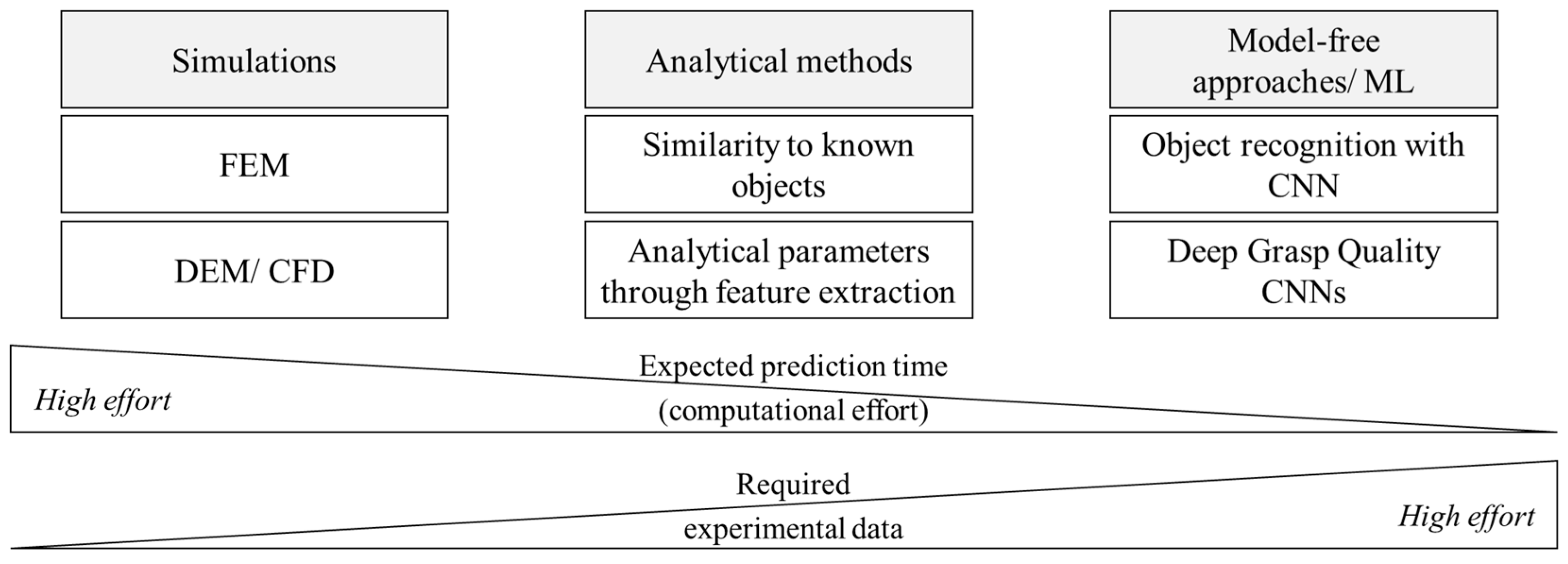
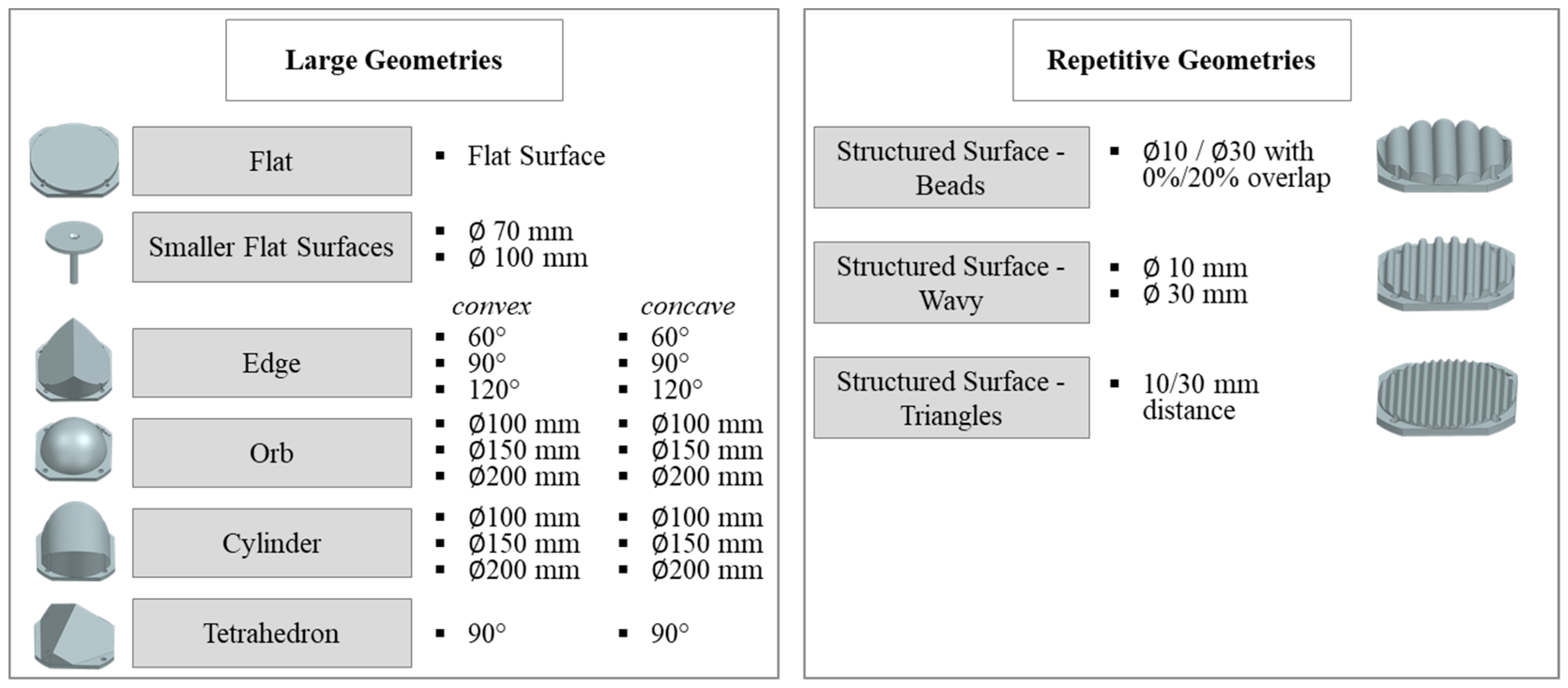
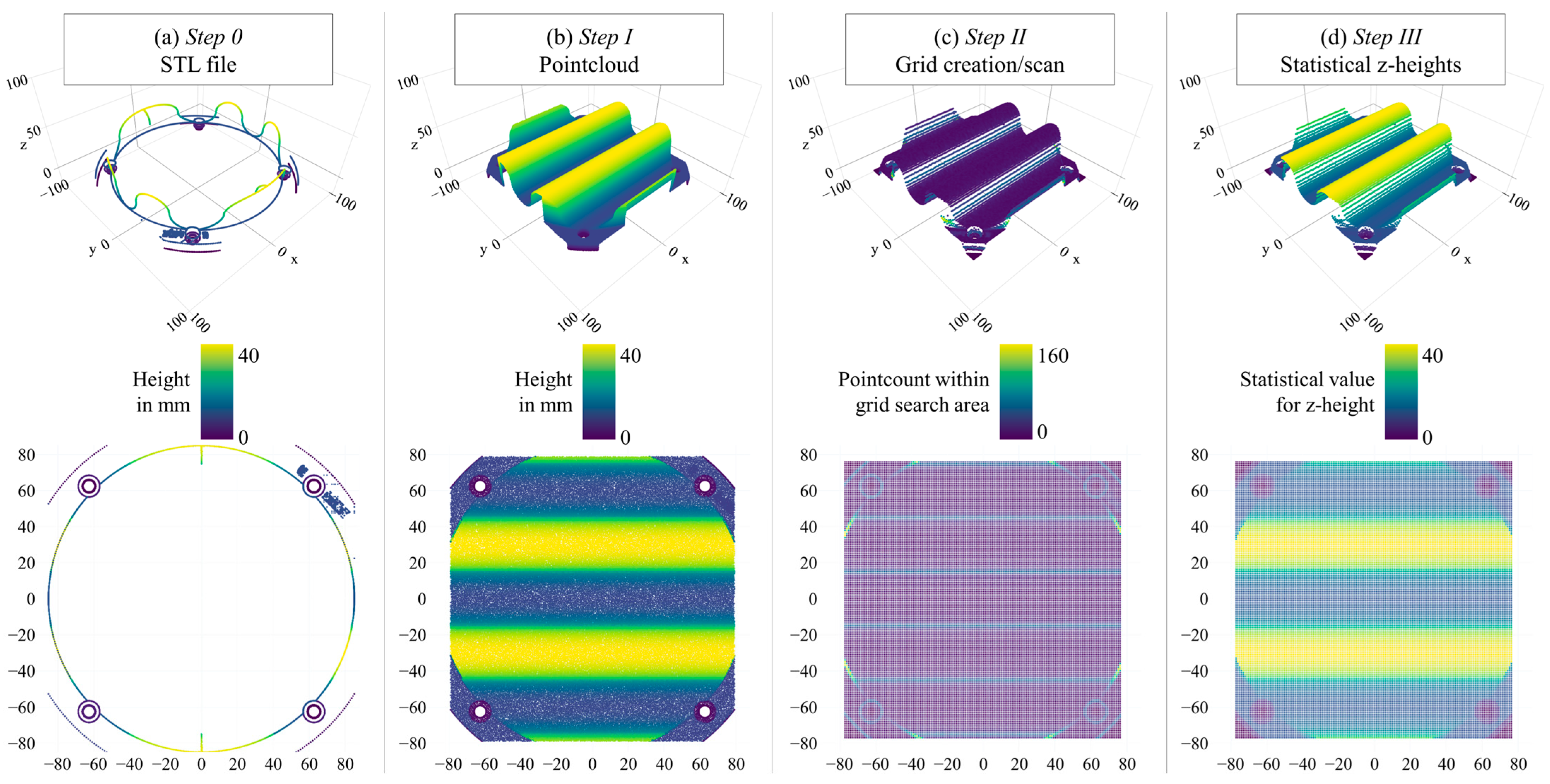
Table 1.
Overview of the advantages and disadvantages of the gripping prediction methods shown within this research.
Table 1.
Overview of the advantages and disadvantages of the gripping prediction methods shown within this research.
| Category | Analytical Contact Score | CPD Comparison |
|---|---|---|
| Applicability to: Variations of known geometries New geometries Air-permeable geometries | RMSE:
| RMSE:
|
| Weaknesses |
|
|
| Required time for real-life application |
|
|
| Applicability for different gripping configurations |
|
|
Table 2.
Possible adaptions to the examined approaches for CPD similarity, as well as Analytical Contact Score (ACS).
Table 2.
Possible adaptions to the examined approaches for CPD similarity, as well as Analytical Contact Score (ACS).
| Applicability | Adaption | Potential | Hinderance |
|---|---|---|---|
| CPD | Additional factors and parameters | Some potential for an increased prediction quality, based on number of training objects | Required amount of training geometries would be very large |
| CPD | Continuous retraining | High potential for a continuously improved prediction quality | Continuously increasing calculation time |
| ACS | Detection of enclosed concave geometry segments | High potential for an increased prediction quality specifically for concave geometries | Increased calculation time |
| ACS | Area-based weighting of the contact score | Some potential for an increased prediction quality, based on number of training objects | Required amount of training geometries would be very large |
| ACS | Adaption of the bordering value towards a cumulative trained value | Some potential for an increased prediction quality | Increased calculation time |
| ACS and CPD | Preliminary classification with Sa_permeability | High potential for an increased prediction quality for handling processes with air-permeable surfaces | Only applicable for handling processes with air-permeable surfaces |
| ACS and CPD | Adaption of a three-dimensional base grid | Some potential for an increased prediction quality | Largely increased calculation time |
| ACS and CPD | Curation of training data for the optimization of specific processes | Some potential for an increased prediction quality specific to an application combined with reduced calculation time | Usability of grippability prediction is then reduced to the specific application ->Reduced versatility |
| ACS and CPD | Adaption of the prediction models towards grippers with different designs and configurations | Potential for a specific selection of an optimal gripper setup with granular materials and membranes for a specific handling application | Requires training data for the new gripper configurations |
Disclaimer/Publisher’s Note: The statements, opinions and data contained in all publications are solely those of the individual author(s) and contributor(s) and not of MDPI and/or the editor(s). MDPI and/or the editor(s) disclaim responsibility for any injury to people or property resulting from any ideas, methods, instructions or products referred to in the content. |
© 2024 by the authors. Licensee MDPI, Basel, Switzerland. This article is an open access article distributed under the terms and conditions of the Creative Commons Attribution (CC BY) license (https://creativecommons.org/licenses/by/4.0/).
Share and Cite
MDPI and ACS Style
Wacker, C.; Dierks, N.; Kwade, A.; Dröder, K. Analytic and Data-Driven Force Prediction for Vacuum-Based Granular Grippers. Machines 2024, 12, 57. https://doi.org/10.3390/machines12010057
AMA Style
Wacker C, Dierks N, Kwade A, Dröder K. Analytic and Data-Driven Force Prediction for Vacuum-Based Granular Grippers. Machines. 2024; 12(1):57. https://doi.org/10.3390/machines12010057
Chicago/Turabian StyleWacker, Christian, Niklas Dierks, Arno Kwade, and Klaus Dröder. 2024. "Analytic and Data-Driven Force Prediction for Vacuum-Based Granular Grippers" Machines 12, no. 1: 57. https://doi.org/10.3390/machines12010057
Note that from the first issue of 2016, this journal uses article numbers instead of page numbers. See further details here.