
A Liquid Nitrogen Cooling Circulation Unit: Its Design and a Performance Study


1
School of Environment and Energy Engineering, Anhui Jianzhu University, Hefei 230009, China
2
Hefei Institutes of Physical Science, Chinese Academy of Sciences, Hefei 230031, China
3
School of Mechanical Engineering, Hefei University of Technology, Hefei 230009, China
*
Author to whom correspondence should be addressed.
Machines 2024, 12(4), 271; https://doi.org/10.3390/machines12040271
Submission received: 19 March 2024
/
Revised: 13 April 2024
/
Accepted: 16 April 2024
/
Published: 18 April 2024
(This article belongs to the Section Machine Design and Theory)
Abstract
:A liquid nitrogen cooling circulating unit is a necessary condition for the stable operation of a cryogenic oscillator, which can provide a stable working environment for the oscillator. In this paper, according to the user’s functional requirements and performance parameters, a closed cooling system with supercooled liquid nitrogen as the medium was designed using SOLIDWORKS 2021 software, which can provide a suitable working environment for the cryogenic oscillator. Combined with the system heat load analysis, theoretical calculation for and the design of the coil heat exchanger, one of the core pieces of equipment of the unit, were carried out. The performance of the designed nitrogen exhaust heater was studied using FLUENT 2021 software, and the velocity field and temperature field of the nitrogen exhaust heater were analyzed. The results show that the outlet temperature of the nitrogen exhaust heating device can reach up to 310 K, and the outlet flow rate of the heating device is 0.01528 kg/s. The experiments on the liquid nitrogen circulating unit using the simulated load equipment show that the refrigeration power of the unit can reach a design index of 600 W, and the temperature of the liquid nitrogen at the liquid outlet of the unit can reach 77.8 K. The experiments also show that the unit meets the design requirements.
1. Introduction
Liquid nitrogen, as a chemically stable refrigerant, can be converted into supercooled liquid nitrogen at temperatures below the saturation temperature at saturation pressure. Liquid nitrogen circulation units, which are based on using supercooled liquid nitrogen as the circulating fluid, have been widely used in monochromators, low-temperature oscillators, superconducting cables, high-temperature superconducting motors, and composite material research due to their excellent cooling effect, controllable flow, and stable pressure [1,2,3,4,5].
In recent years, scholars have conducted a large amount of research on supercooled liquid nitrogen cooling. They found that superconducting materials would enter a superconducting state under the temperature zone of liquid nitrogen, the resistivity of the current would disappear, and almost lossless power transmission could be achieved. Superconducting cables made with superconducting materials are capable of transmitting three to five times more power than conventional cables, and the low-temperature environment provided by a cooling system is a key factor in the proper operation of high-temperature superconducting cables [6]. High-temperature superconducting cable cooling systems mainly use liquid nitrogen as the cooling medium. The use of supercooled liquid nitrogen to cool the inverter equipment significantly improves the efficiency and power density of power conversion systems [7]. In addition, the use of cooling equipment to cool electronic devices allows for a higher power density, higher efficiency, and better performance in a variety of applications [8,9,10].
A low-temperature environment is required for the operation of permanent magnet oscillators. The use of a liquid nitrogen cooling system to provide a low-temperature environment can increase the peak magnetic field of permanent magnets by 30 to 50 percent, allowing for higher-brightness X-ray synchrotron light and improving the radiation resistance of the oscillator [11]. As one of the most commonly used cooling methods in the world, the liquid nitrogen cooling method has been validated through multiple experiments at the European Synchrotron Radiation Source (ESRF) and France Soleil [12,13]. In 2017, Liu L. and other scholars proposed a design scheme for a supercooled liquid nitrogen cooling system and analyzed and calculated the total resistance of the system [14]. Subsequently, Xiang Z. and other scholars studied the impact of the pressure stability on the operation of the supercooled liquid nitrogen cooling system [15]. Wang S. and other scholars proposed a design scheme for the liquid nitrogen cooling system and researched the dynamic heat load under working conditions [16]. A reliable liquid nitrogen cooling system is essential for the proper operation of a cryogenic oscillator.
Based on the existing research, a liquid nitrogen cooling circulation unit was designed, the thermodynamic performance of the unit was studied, and the relationship between the refrigeration power and the circulation flow was obtained by changing the circulation flow of the unit. This paper provides a theoretical basis for the subsequent research on liquid nitrogen cooling circulation units.
2. System Design
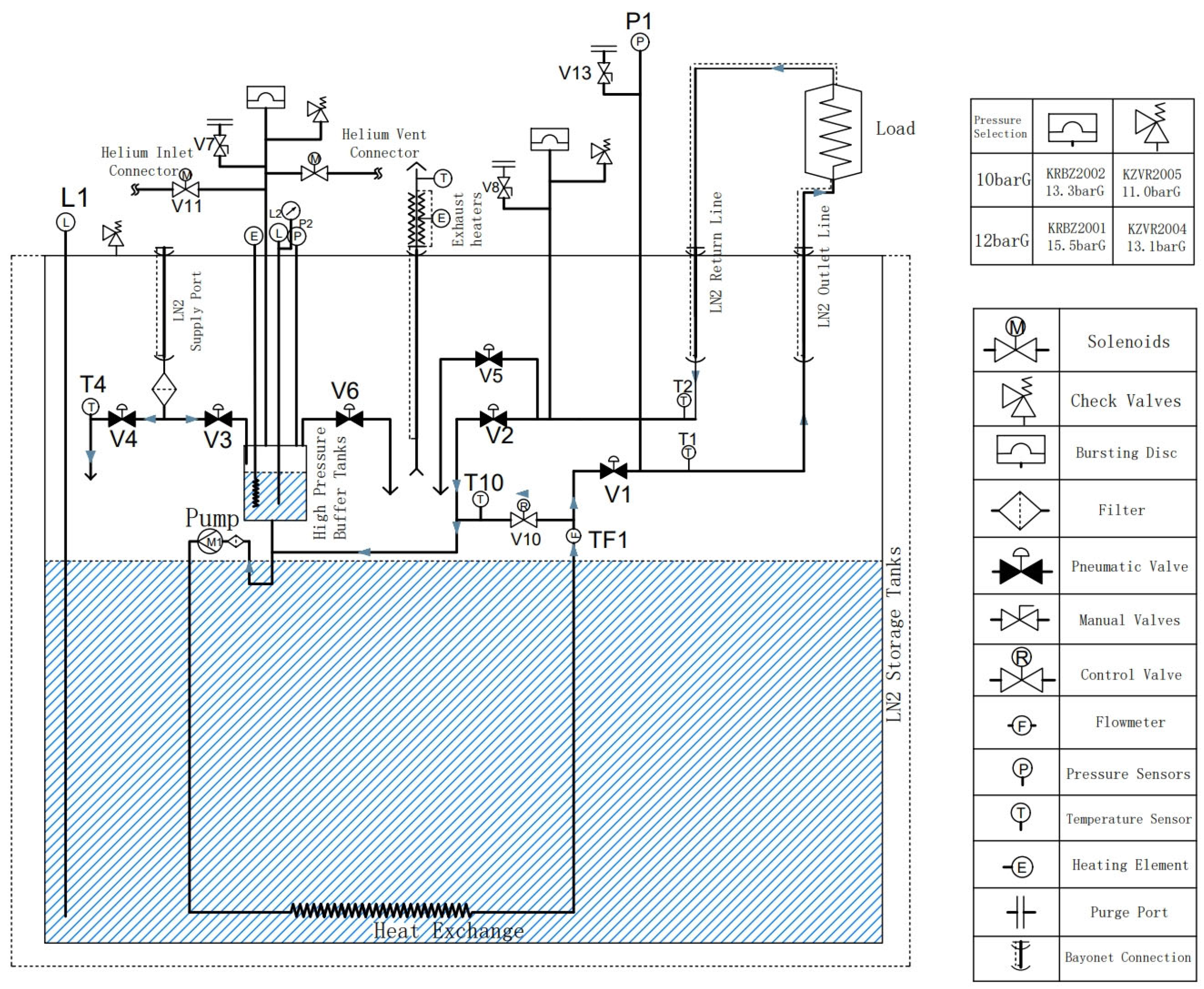
The process of the liquid nitrogen cooling cycle unit is shown in Figure 1. The unit mainly consists of a tank body, a liquid nitrogen pump, a high-pressure buffer tank, an exhaust heating wire, a heat exchange coil, and various valves. During operation, the vibration of the liquid in the cycle must be small enough, and larger vibrations may have irreversible effects on the cryogenic oscillator equipment. It is known from the physical properties of the liquid that when the pressure changes, the boiling point will also change. As the cooling carrier, the liquid nitrogen in the closed cycle must maintain a temperature below boiling point to prevent boiling and generate vibration. The unit adjusts the pressure of the pressure setting unit (a closed-loop pressure control unit composed of a high-pressure buffer tank, a liquid level gauge, a heater, a pressure relief valve, etc.) hanging at the inlet of the liquid nitrogen pump in the circulation pipeline according to the cooling capacity required by the monochromator and the total heat leakage of the closed-loop circuit. The pressure at the inlet of the liquid nitrogen pump is maintained above the supercooling pressure, where the liquid nitrogen does not vaporize. In the experiment, the pressure in the cycle is controlled using the pressure setting unit at the pump inlet and maintained at 2~10 bar.
The outlet of the liquid nitrogen pump is connected to a coil-type heat exchanger device. As one of the core components of the unit, the coil-type heat exchanger is immersed in a normal-pressure liquid nitrogen storage tank. Through convective heat exchange, the high-pressure liquid nitrogen in the tube is supercooled to 77 K and then transported to the user’s monochromator cooling interface through the liquid nitrogen output pipeline. After the supercooled liquid nitrogen absorbs the heat generated by the user end, the temperature rises, and it flows back to the unit through the liquid nitrogen return pipeline to complete the closed cycle.
According to the design indicators, the liquid nitrogen circulation unit needs to control the temperature of the monochromator crystal at 77~85 K. The specific requirements are shown in Table 1.
2.1. System Heat Load
To ensure that the liquid nitrogen circulation unit establishes stable subcooled liquid nitrogen circulation, it is necessary to calculate the heat loss and radiation heat loss of the components in the unit that are under low-temperature conditions, including high-pressure buffer tanks, pipelines, valves, and other components, while considering the heat load of equipment such as the monochromator. The internal components of the liquid nitrogen circulation unit are mainly made of stainless steel, and the radiation heat transfer can be simplified according to the gray body. The following formula can be used to calculate the heat loss:
where Q is heat loss; T1 is the external environment temperature; T2 is the temperature in the circulation tube; is the emissivity of the pipe wall; and is the Stefan–Boltzmann constant.
The emissivity of the pipe wall ; the external environment temperature T1 is 300 K; the temperature inside the circulation pipe T2 is 77 K.
The total heat loss of the liquid nitrogen circulation unit was calculated to be approximately 500 W.
2.2. Coil and Tube Heat Exchanger Design
To achieve the supercooling state of liquid nitrogen in the cycle, it is first necessary to pressurize the cycle to 2~3 bar using the high-pressure buffer tank connected at the inlet of the liquid nitrogen pump. As the pressure increases, the boiling point of liquid nitrogen also rises. After the liquid nitrogen passes through the coil-type heat exchanger, the excess heat of the high-pressure liquid nitrogen in the cycle is transferred to the normal-pressure 77 K saturated liquid nitrogen in the unit tank to achieve a supercooled state. According to the design usage requirements, the maximum flow rate of liquid nitrogen is 10 L/min, the working pressure of liquid nitrogen is adjustable between 2 and 10 bar, and the pressure fluctuation during operation is less than 1 mbar. Copper is chosen as the material for the heat exchanger. The three-dimensional structure of the coil-type heat exchanger is shown in Figure 2.
To meet the maximum cooling demand at the user end, the heat exchanger coil of the unit is selected and calculated according to the expected heat exchange value of 2500 W. The design of the heat exchanger mainly confirms the length of the coil. The high-pressure, supercooled liquid nitrogen in the heat exchanger exchanges heat with the inner wall of the tube through convective heat exchange. The normal-pressure liquid nitrogen in the normal-pressure storage tank inside the unit exchanges heat with the outer wall of the tube through boiling heat exchange. The maximum flow rate of liquid nitrogen in the high-pressure circuit is 10 L/min, so the design basis is that when the pipe flow rate is 10 L/min, the heat exchange can reach 2500 W.
We selected a copper pipe with an outer diameter of 18 mm and a wall thickness of 1.5 mm; the calculated flow rate is 0.94 m/s. The physical properties of liquid nitrogen are as follows: , , , . Substituting the above data into the formula:
where Re is the Reynolds number; Pr is the Prandtl number; is the fluid density; is the dynamic viscosity; Cp is the constant pressure ratio; is the thermal conductivity; and v is the rate.
We substitute Re and Pr into the formula for the convective heat transfer coefficient inside the coil [17]:
where h1 is the convective heat transfer coefficient; R the middle diameter of the heat exchanger coil; and d1 the inner diameter of the coil.
The calculation formula for the other parameters required by the subcooled heat exchanger is as follows:
where m is mass; Tm, neutral temperature; A, area; and L, length.
The coil heat exchanger is immersed in a liquid nitrogen bath at a normal pressure of 77 K. Due to the low temperature difference, the heat exchange method between the outer wall of the heat exchanger and the liquid nitrogen at normal pressure is transition boiling heat exchange [18,19].
where Nu is the Nusselt number; Gr is the Grawshaw number; h2, the coefficient of convection heat transfer outside the tube; and D, characteristic length.
The heat exchange area outside the tube is the same as the heat exchange area inside the tube, and the heat exchange amount is also the same.
After calculation, the heat flux density of forced convection heat transfer is 5222.04 W∙m−2, the heat exchange area is 0.479 m2, and the coil length is 10.17 m.
2.3. Exhaust Heating Device Design
2.3.1. Heating Power
The liquid nitrogen cooling cycle unit mainly uses the evaporation of liquid nitrogen from the cryogenic storage tank to absorb the heat generated by the coil heat exchanger. The generation of nitrogen gas will cause the pressure in the tank to rise sharply. To maintain pressure stability in the tank, it is necessary to promptly discharge the generated low-temperature nitrogen gas. To prevent the gasified low-temperature nitrogen from condensing the water vapor in the air and clogging the exhaust piping during the discharge process, it is necessary to heat the generated low-temperature nitrogen.
The nitrogen exhaust heater as a whole adopts an internal winding resistance wire structure. The nitrogen is divided into 10 regions within the exhaust pipe through a perforated circular plate, with a resistance wire wound in each region. The perforated circular baffle is fixed by suspending a threaded rod from the top. The structure of the perforated circular baffle not only causes the nitrogen to recirculate within the pipe, enhancing heat exchange, but it can also better zone the temperature, increasing the heat exchange area of the nitrogen. A temperature measurement hole is reserved at the outlet of the exhaust pipe, and the exhaust temperature is measured using a temperature sensor. According to the temperature feedback signal, the output power of the silicon-controlled rectifier is adjusted, thereby adjusting the outlet temperature of the nitrogen, realizing intelligent temperature control regulation of the nitrogen discharge device. The silicon-controlled rectifier is installed on the outer pipe of the nitrogen discharge heating device, close to the outlet position. The nitrogen exhaust heater is connected to the top cover of the liquid nitrogen circulation unit by threads.
The overall heat leakage of the unit is about 500 W, so the total heat absorbed by the vaporization of liquid nitrogen Q1 = 2500 W + 500 W = 3000 W. After determining the overall heat load of the liquid nitrogen circulation unit, the evaporation rate of the liquid nitrogen is determined using Formula (14).
The calculated mass of nitrogen gas produced per second is m = 15.28 g.
Knowing the generation rate of nitrogen gas in the tank, the required heating power Q2 = 3961.9 W is calculated. Considering the heating power value of the device and the working environment temperature of the heating wire, a nickel–chromium heating wire suitable for low-temperature heating is selected in the design, and the surface is coated with insulating material. The technical parameters and specifications of the heating wire are shown in Table 2.
Referring to the technical specifications and parameters of the resistance wire material in Table 2, the working current is determined to be 2.0 A. According to Joule’s law, the resistance value R is calculated, and the required length of the resistance wire L = 29.7 m is calculated based on the resistance value per unit length. To ensure that the working current of the nitrogen gas exhaust heating device can still be maintained at 2.0 A under the condition of a 220 V total voltage power supply, 9 resistance wires with a length of 3.3 m are installed in the nitrogen gas exhaust device in parallel.
2.3.2. Nitrogen Exhaust Heater Structure
The nitrogen discharge heating device that was designed had a pipe length of 420 mm, an inner pipe diameter of 60 mm, and an outer pipe diameter of 66 mm. A vacuum insulation structure was adopted between the outer pipe and the inner pipe that could effectively insulate the low-temperature nitrogen inside, prevent a large amount of condensation water from appearing on the outer pipe wall, and leave a vacuum extraction interface, which could be vacuumed regularly to maintain a good insulation effect. To ensure that the outlet temperature of the low-temperature nitrogen after being heated by the resistance wire was above the ambient dew point temperature, a perforated circular baffle structure was designed inside the pipe, which not only increased the flow resistance of the nitrogen discharge but also increased the heat exchange time and increased the heat exchange area of the nitrogen. The hole at the center of the circle was used to install the silk rod to fix its position; at the same time, according to the winding arrangement of the resistance wire and the mass flow rate of the nitrogen discharge q = 15.28 g/s, it was determined that the inner diameter of the nitrogen exhaust heater pipe was 60 mm and the outer diameter was 66 mm. The overall structure of the nitrogen discharge heating device is shown in Figure 3.
2.3.3. Model Building and Meshing
Geometry was used to model the geometry of the nitrogen discharge heating unit and to name the inlet and outlet of the nitrogen exhaust unit. ANSYS mesh software was used to mesh the nitrogen discharge heating device, and the boundary expansion layer was set at the pipe wall. To ensure the accuracy and economy of the calculation, mesh irrelevance verification and mesh quality checks are essential steps. Three different sizes of meshes were divided, and the numbers of meshes were 1.5 million, 1.7 million, and 2.1 million, respectively. By comparing and analyzing the calculation results, it can be seen that when the number of grids is 1.7 million or 2.1 million, the difference between the calculation results is small enough, and from the point of view of computational economy, finally, the simulation chooses to participate in the calculation with a grid of 1.7 million; similarly, the quality of the mesh has a great impact on the calculation accuracy and stability, which mainly include the distribution of the nodes, smoothness, skewness, and so on. Therefore, after generating the mesh, it is necessary to check the quality of the mesh, and the results show that the overall quality of the mesh was above 0.5, which meets the requirements of the calculation, and the calculation mesh is shown in Figure 4.
2.3.4. FLUENT Parameter Settings
For the inlet and outlet of the flow, Fluent provides ten types of boundary units: velocity inlet, pressure inlet, mass inlet, pressure outlet, pressure far field, mass outlet, air inlet, air fan, air outlet, and exhaust fan.
Based on the pipe diameter, the inlet speed of the nitrogen discharge was calculated, and the inlet boundary type was set as a velocity inlet. The heated nitrogen was directly discharged into the atmospheric environment, so the outlet boundary type was set as a free jet. In this simulation, the operating pressure was set at 1.01325 × 10⁵ Pa. Considering that the interlayer between the inner and outer pipes of this device would be vacuumed for insulation, the heat transfer was minimal and could be ignored; therefore, in this simulation, the boundary type of the inner pipe wall was set as an adiabatic wall.
A standard turbulence model was chosen for the flow. The model predicts the free shear flow propagation rate to be like a wake, mixing the flow, flat plate disturbances, cylindrical bypasses, and radioactive jets, and hence is suitable for both wall-bound and free shear flows. The discrete equation had been set to a first-order format, and the SIMPLE algorithm was chosen in the segregated solver.
The temperature distribution of the central cross-section of the nitrogen gas discharge heating device is shown in Figure 5. From the figure, it can be seen that the temperature near the outlet of the nitrogen gas exhaust device is 310 K, which is significantly higher than the environmental dew point temperature, indicating that the heating wire’s electric power and structural design can meet the conditions. Secondly, the electric heating power can be automatically adjusted according to the temperature feedback. In actual operation, the outlet temperature value can be set to be 1~2 °C higher than the environmental dew point temperature to reduce the energy consumption of the device.
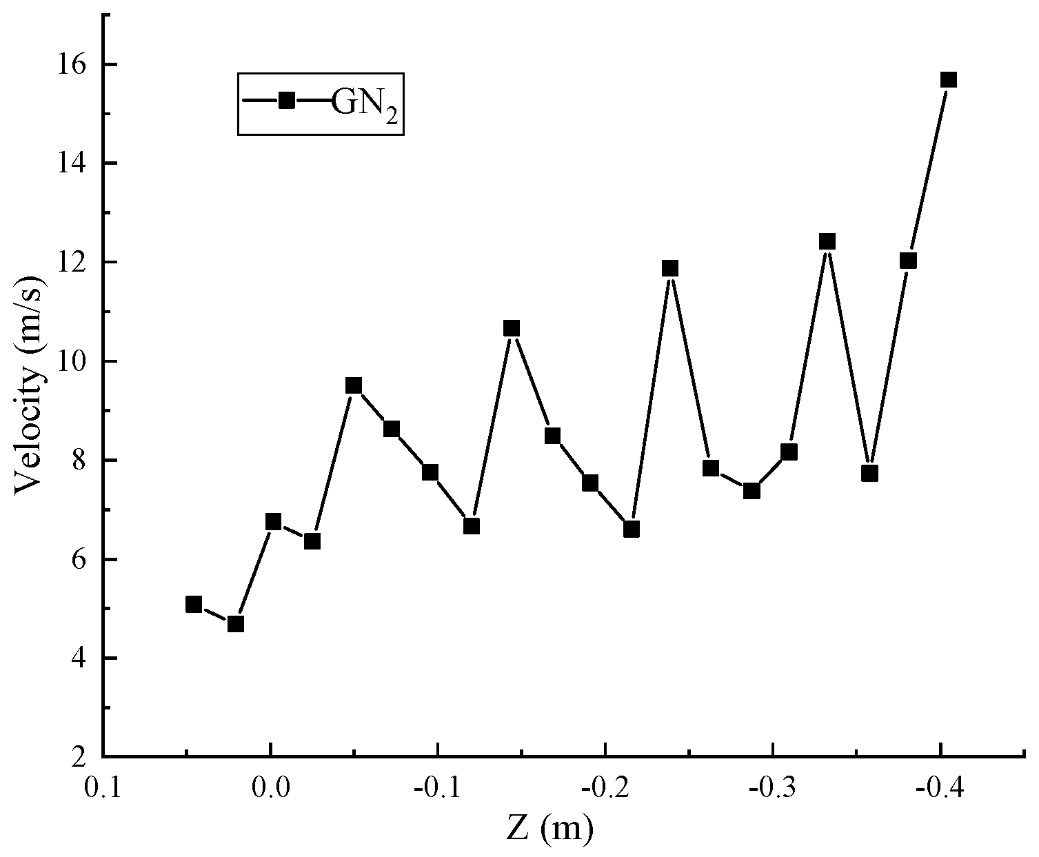
The change in magnitude of the internal nitrogen gas flow velocity of the nitrogen gas exhaust heating device in the Z-axis direction is shown in Figure 6. From the figure, it can be seen that the inlet speed of nitrogen gas is 5 m/s. After it enters the exhaust heating device, under the action of electric heating and pressurization and the obstruction of the baffle, the exhaust speed of nitrogen gas will fluctuate and increase, reaching a peak at the outlet with an average outlet speed of 16 m/s.
Using the CFD-Post 2021 software, the outlet mass flow rate of the nitrogen discharge heating device was calculated to be q = 0.01528 kg/s, which was the same as the calculated nitrogen flow rate. Therefore, the mass flow rate met the design requirements.
2.4. Design of Mechanical Structures
The mechanical structure design of the liquid nitrogen circulation unit is shown in Figure 7. The tank is approximately 1.5 m high and has a diameter of approximately 0.8 m. The main force components of the liquid nitrogen circulation unit include the vacuum chamber, upper cover plate, liquid nitrogen storage tank, and high-pressure buffer tank. To facilitate later processing and save production costs, standard elliptical heads were selected for the vacuum chamber and liquid nitrogen storage tank while meeting the design requirements. The liquid nitrogen storage tank and the vacuum chamber are connected by welding flanges, and O-ring fluorine rubber sealing rings are used between the two flanges and between the flange and the cover plate. The interlayer between the vacuum chamber and the liquid nitrogen storage tank is maintained using an external molecular pump unit connected through the KF25 interface opened on the side wall of the chamber. External measuring and control components such as the switches/regulating valves, liquid level gauges, flow meters, and pressure and temperature sensors, as well as the liquid nitrogen output, return, and supply pipelines, are all connected to the unit through the upper cover plate to control the opening and closing of the internal loop of the unit to provide subcooled single-phase liquid nitrogen and purging and vacuuming functions for the load and to monitor the liquid nitrogen level, pipeline pressure, and flow rate in real time. Therefore, the upper cover plate will open the corresponding threaded holes or passages according to the requirements (connected to the cover plate by welding) and ensure sufficient strength to support the gravity load of the above components.
3. Experimental Testing of the Liquid Nitrogen Circulation Unit
To study whether the cooling capacity of the liquid nitrogen circulation unit met the design requirements, a simulated load device was set up for the experiment. Figure 8 shows the experimental site. In the experiment, the simulated load was set to 600 W. The temperature of the liquid nitrogen at the load inlet and the temperature of the liquid nitrogen after absorbing the load heat were confirmed using thermometers T1 and T2 on the liquid nitrogen output pipeline and the return pipeline. The Rosemount 3051 pressure transmitter was chosen to confirm the circulation flow rate of the unit.
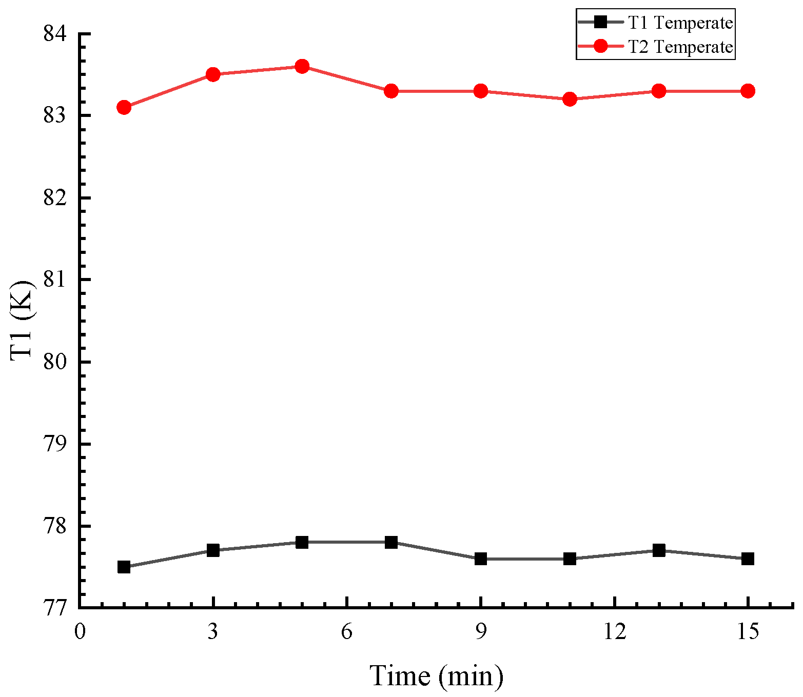
The liquid nitrogen import and export temperatures during the operation of the liquid nitrogen cooling cycle unit are shown in Figure 9. As can be seen from the figure, under a certain circulating flow rate, the temperature of the liquid supply of the unit is maintained within a certain range, the temperature fluctuation is small, and the temperature of the liquid supply is stable. The temperature difference between the output temperature of liquid nitrogen and the return temperature of liquid nitrogen during normal operation is about 5 K, which meets the design requirements.
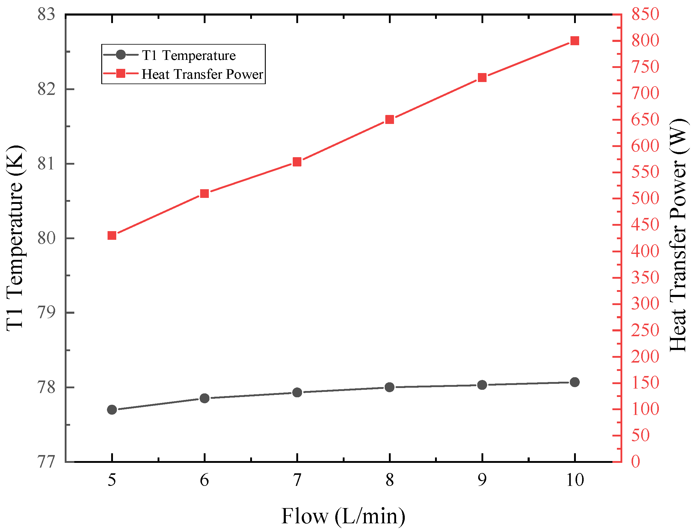
The liquid nitrogen supply port temperature and the refrigeration power of the liquid nitrogen cooling cycle unit under different circulating flow rates are shown in Figure 10. As can be seen from the figure, the refrigeration power of the liquid nitrogen cooling cycle unit is related to the circulating flow rate. When the circulating flow rate of the unit is increased, the temperature of the outlet liquid nitrogen rises slightly, but the heat exchange volume increases significantly. This is because the convective heat transfer coefficient in the tube increases with the flow rate. When the circulation flow rate reaches a maximum of 10 L/min, the refrigeration power of the unit can reach 800 W.
4. Conclusions
This article designs a liquid nitrogen cooling circulation unit device for low-temperature oscillators. By applying theoretical knowledge of heat transfer and engineering thermodynamics, the heat exchange area of the coil heat exchanger was calculated, and the structural parameters of the coil were confirmed. ANSYS was used to simulate and analyze the nitrogen exhaust heating device, determining its performance, stability, and reliability. The nitrogen exhaust heating device, through the combination of a multi-layer partition internal structure and automatic control of the exhaust outlet temperature, not only achieved efficient heating of the exhaust in a limited volume but also realized automatic control of the exhaust temperature. According to the simulation results, the temperature field, velocity field, and mass flow rate of the device were obtained. Through the software’s calculation of the mass flow rate of the nitrogen exhaust heating device outlet q = 0.01528 kg/s, it could be seen that the outlet temperature and nitrogen outlet flow of the device could meet the design requirements. It could be used in intelligent liquid nitrogen circulation units with a compact structure, high heating efficiency, and strong environmental adaptability.
After the system was assembled, thermodynamic performance studies were conducted on the unit using simulated load equipment. The experiment showed that the unit’s liquid supply temperature was stable, the maximum refrigeration power could reach 800 W, and all the indicators met the design requirements. Its structure was compact, and the cooling was efficient. At the same time, this design could also provide certain references and engineering experience for the development of other cooling devices.
Author Contributions
Conceptualization, J.Y. and Q.W.; methodology, J.Y. and Y.X.; software, J.Y.; validation, J.Y., Q.W. and X.L. (Xiao Liu); formal analysis, J.Y.; investigation, Y.X.; resources, J.Y., X.L. (Xiangyou Lu) and Y.X.; data curation, J.Y.; writing—original draft preparation, J.Y.; writing—review and editing, J.Y. and Y.X.; visualization, J.Y.; supervision, Y.X. and X.L. (Xiao Liu); project administration, J.Y.; funding acquisition, J.Y. All authors have read and agreed to the published version of the manuscript.
Funding
This work was supported by Comprehensive Research Facility for Fusion Technology Program of China under Contract No. 2018-000052-73-01-001228.
Data Availability Statement
Data are contained within the article.
Acknowledgments
The authors greatly appreciate the anonymous referees for their valuable suggestions and questions.
Conflicts of Interest
The authors declare no conflicts of interest.
References
- Wang, J.; Gao, L.; Jia, Q. Study on thermal mechanical coupling of Laue crystal monochromator cooled by LN2. Cryog. Supercond. 2022, 50, 47–50. [Google Scholar]
- Zhang, X.; Xu, M.; Sun, L. Design and Experimental Study of Subcooled Liquid Nitrogen Circulation for the Cryogenic Permanent Magnet Undulator. J. Eng. Thermophys. 2022, 43, 1761–1767. [Google Scholar]
- Li, J.; Zhang, L.; Cao, Y. Design and operation analysis of cooling system for cold dielectric high temperature superconducting cable. Cryog. Supercond. 2020, 48, 7–11+24. [Google Scholar]
- Ge, T. Study on Cooling Process of High Speed Brushless Doubly-Fed Superconducting Generator; Harbin Institute of Technology: Harbin, China, 2015. [Google Scholar]
- Zhang, H.; Qu, L.; Ding, C. Study of Surface Integrity of SiCp/Al Composites Using High-Speed Milling under Cryogenic Liquid Nitrogen Conditions. Machines 2023, 11, 608. [Google Scholar] [CrossRef]
- Tang, Y.; Yu, Z.; Zhu, S. Current situation and development of cooling system for HTS cable. Cryog. Supercond. 2019, 47, 1–8. [Google Scholar]
- Hassan, M.S.; Asano, T.; Shoyama, M.; Dousoky, G.M. Performance Investigation of Power Inverter Components Submersed in Subcooled Liquid Nitrogen for Electric Aircraft. Electronics 2022, 11, 826. [Google Scholar] [CrossRef]
- Haldar, P.; Ye, H.; Efstathiadis, H.; Raynolds, J.; Hennessy, M.; Mueller, O.; Mueller, E. Improving Performance of Cryogenic Power Electronics. IEEE Trans. Appl. Supercond. 2005, 15, 2370–2375. [Google Scholar] [CrossRef]
- Rajashekara, K.; Akin, B. Cryogenic Power Conversion Systems: The Next Step in the Evolution of Power Electronics Technology. IEEE Electrif. Mag. 2013, 1, 64–73. [Google Scholar] [CrossRef]
- Dogmus, E.; Kabouche, R.; Lepilliet, S.; Linge, A.; Zegaoui, M.; Ben-Ammar, H.; Chauvat, M.-P.; Ruterana, P.; Gamarra, P.; Lacam, C.; et al. InAlGaN/GaN HEMTs at Cryogenic Temperatures. Electronics 2016, 5, 31. [Google Scholar] [CrossRef]
- Harat Tanaka, T.; Kitamura, H. Cryogenic permanent magnet undulators. Phys. Rev. Spec. Top. Accel. Beams 2004, 7, 050702. [Google Scholar]
- Charles, K. Development of a Cryogenic Permanent Magnet Undulator at the ESRF. Eur. Synchrotron Radiat. Facil. 2008, 12, 68–69. [Google Scholar]
- Benabderrahmane, C.; Béchu, N.; Berteaud, P. Development of a 2m Pr2Fe14B Cryogenic Permanent Magnet Undulator at SOLEIL. J. Phys. Conf. Ser. 2013, 425, 032019. [Google Scholar] [CrossRef]
- Liu, L.; Wang, J.; Wang, S. Development of sub-cooled liquid nitrogen cooling system for CPMU. Nucl. Tech. 2017, 40, 070101. [Google Scholar]
- Zhang, X.; Xu, M.; Sun, L. Experimental investigation and analysis on the pressure stabilization of subcooled liquid nitrogen circulation for the HEPS. Cryogenics 2022, 128, 103602. [Google Scholar]
- Wang, S.; Li, M.; Wu, T. Design and Dynamic Thermal Load Test of Liquid Nitrogen Cooling System for SSRF Cryogenic Permanent Magnet Undulator. Cryog. Supercond. 2022, 28, 346–352. [Google Scholar]
- Chen, G.; Jin, T.; Tang, K. Low Temperature Heat and Equipment; National Defence Industry Press: Beijing, China, 2008; pp. 36–45. [Google Scholar]
- Zhang, H.; Wang, J. Experimental study on nitrogen bubble rising velocity in bottom of circular pipe. J. Eng. Thermophys. 2006, 27, 233–236. [Google Scholar]
- Kagan, A.M.; Gelperin, I.I. Investigation of Heat Transfer from Liquid Nitrogen to the Surface of a Vertical Tube with Variable Thermal Loading. Chem. Pet. Eng. 1971, 7, 218–221. [Google Scholar] [CrossRef]
Figure 1.
Liquid nitrogen cooling circulation unit flow chart.

Figure 2.
Schematic diagram of the three-dimensional structure of coil and tube heat exchanger.
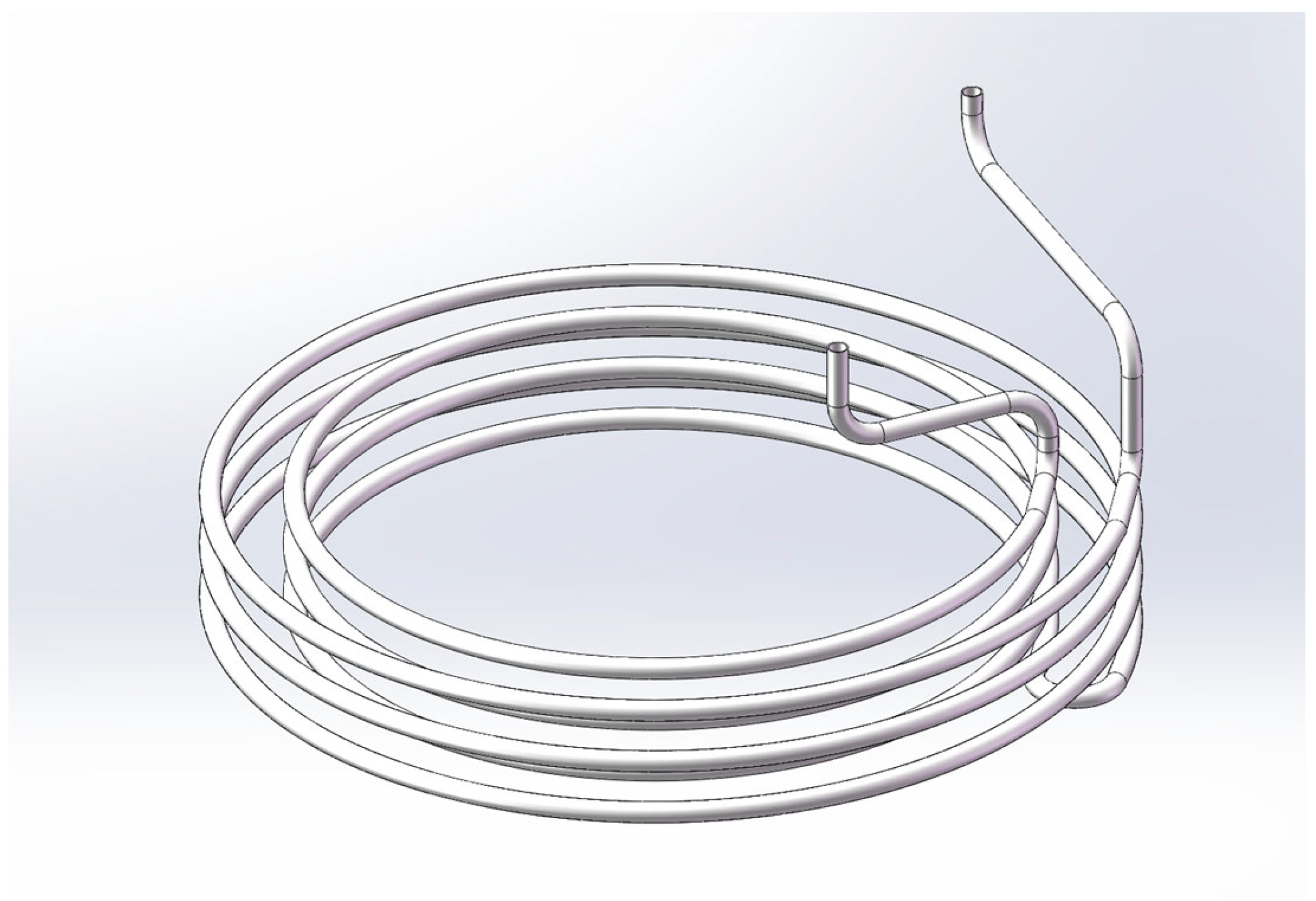
Figure 3.
(a) Front view of the nitrogen gas exhaust heater, (b) cross-sectional view of the nitrogen gas exhaust heater.
Figure 3.
(a) Front view of the nitrogen gas exhaust heater, (b) cross-sectional view of the nitrogen gas exhaust heater.
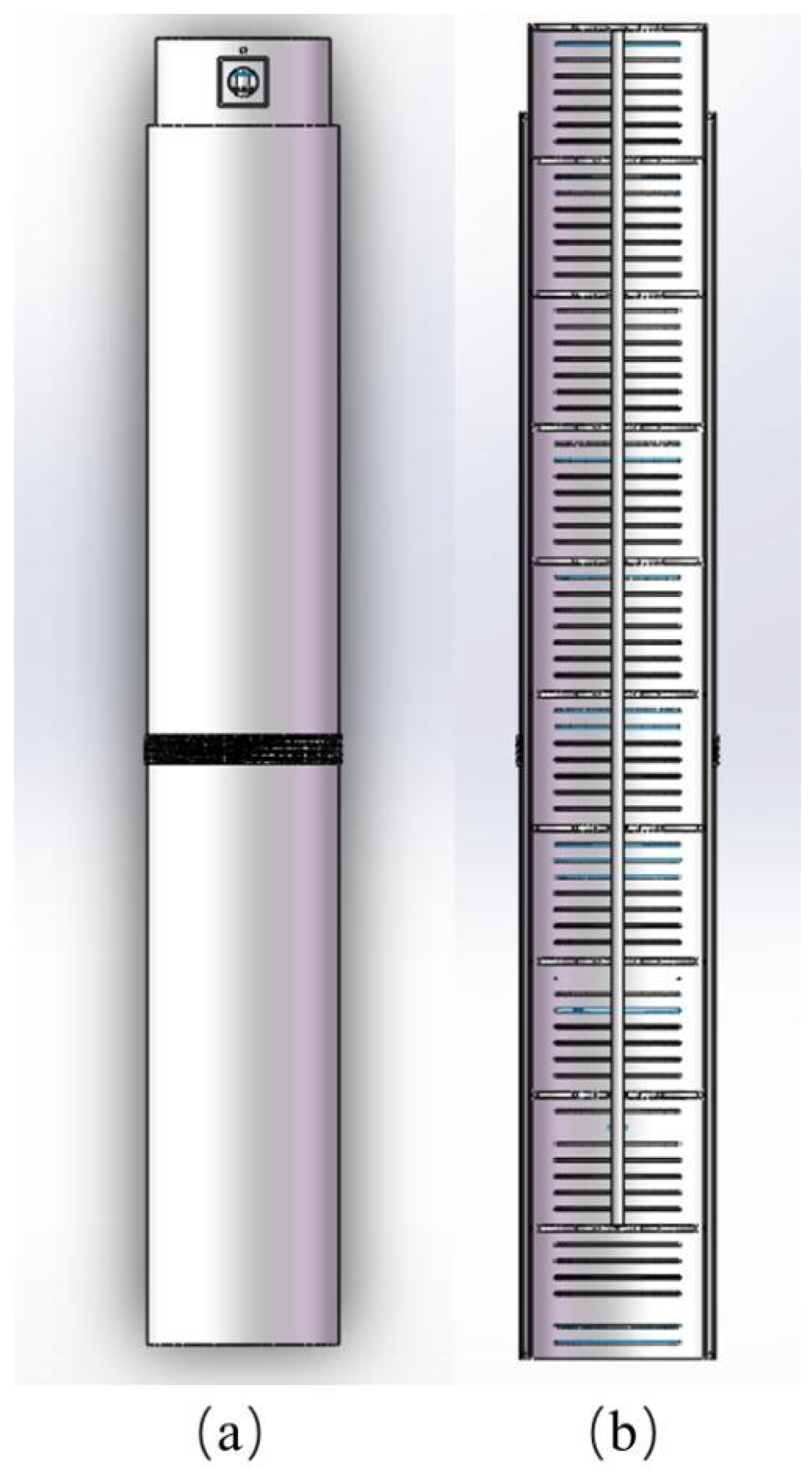
Figure 4.
(a) Nitrogen exhaust heater outlet cross-section grid, (b) nitrogen exhaust heater piping profile grid.
Figure 4.
(a) Nitrogen exhaust heater outlet cross-section grid, (b) nitrogen exhaust heater piping profile grid.

Figure 5.
Temperature distribution cloud diagram of the central cross-section of the nitrogen gas discharge heater.
Figure 5.
Temperature distribution cloud diagram of the central cross-section of the nitrogen gas discharge heater.
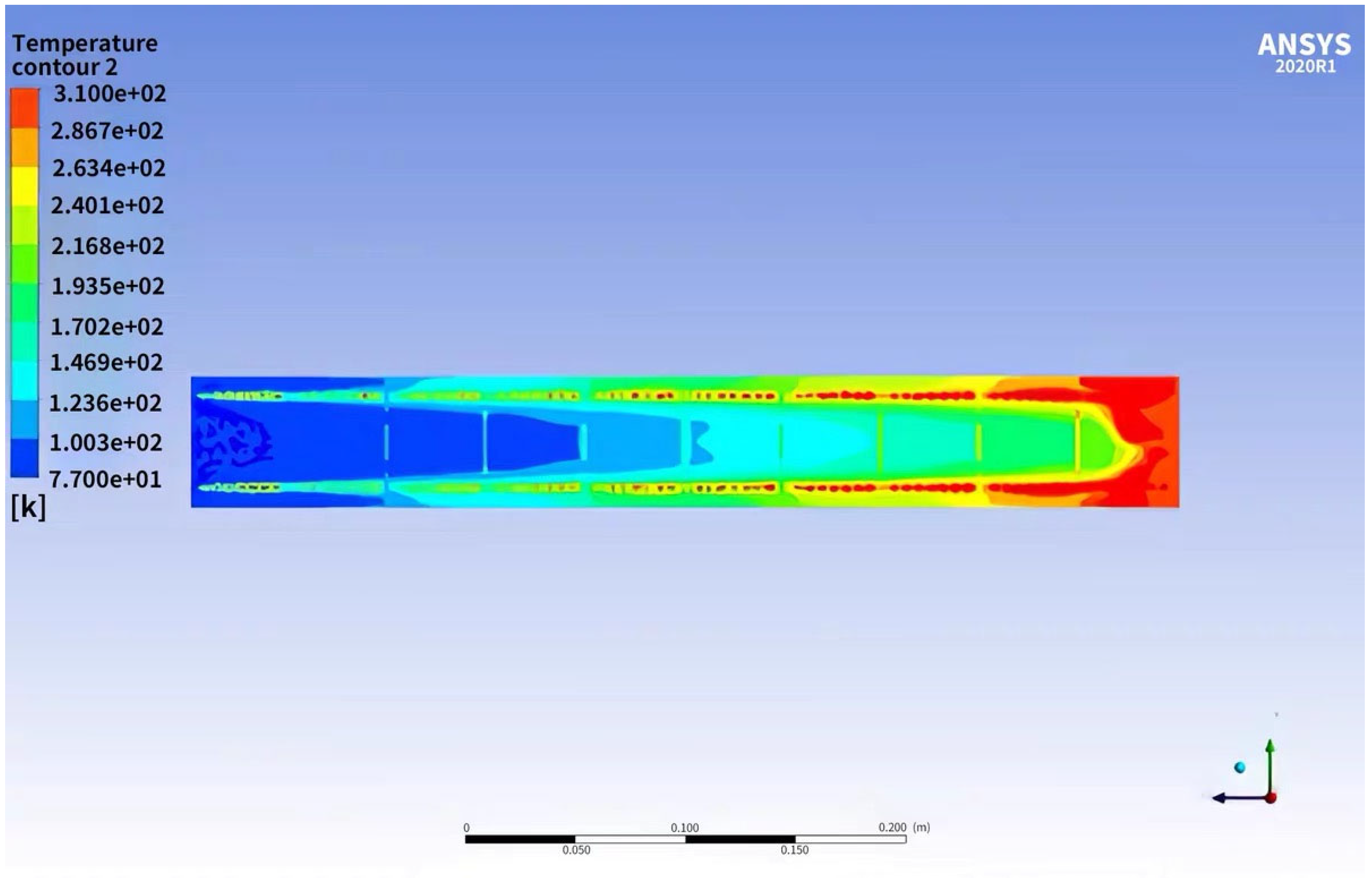
Figure 6.
Average velocity of nitrogen gas in the nitrogen gas discharge heater along the Z-axis direction.
Figure 6.
Average velocity of nitrogen gas in the nitrogen gas discharge heater along the Z-axis direction.

Figure 7.
Structural design of liquid nitrogen circulation unit.
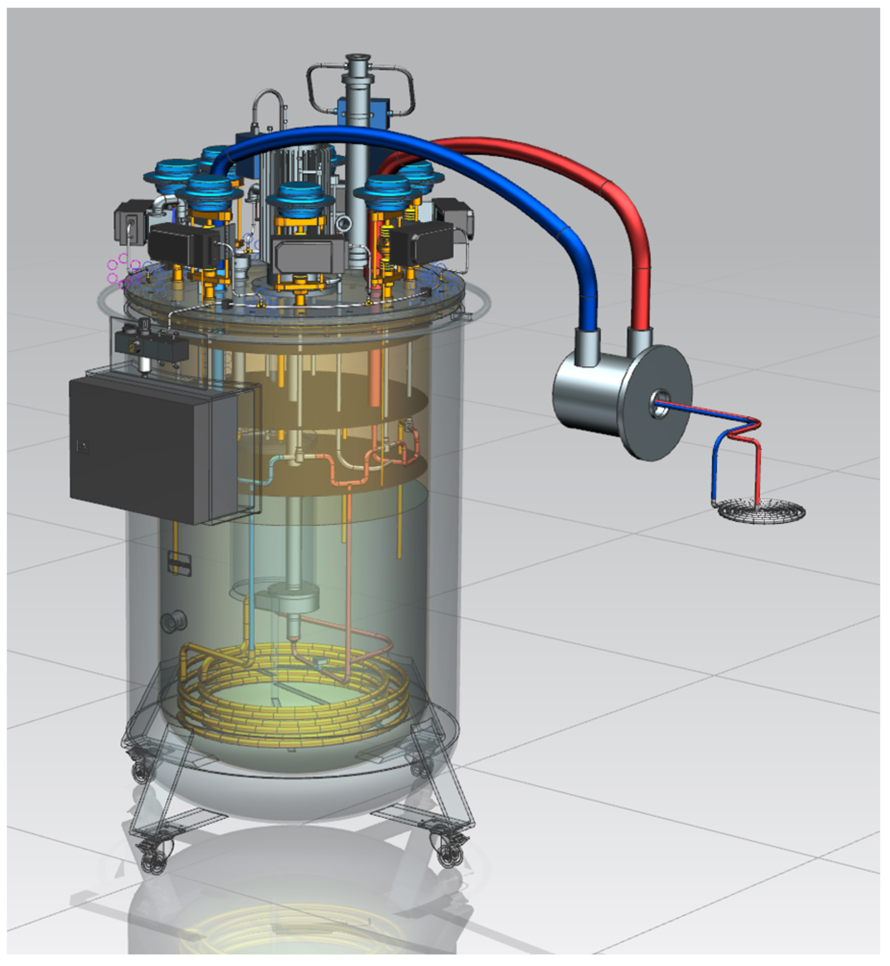
Figure 8.
Experimental site.
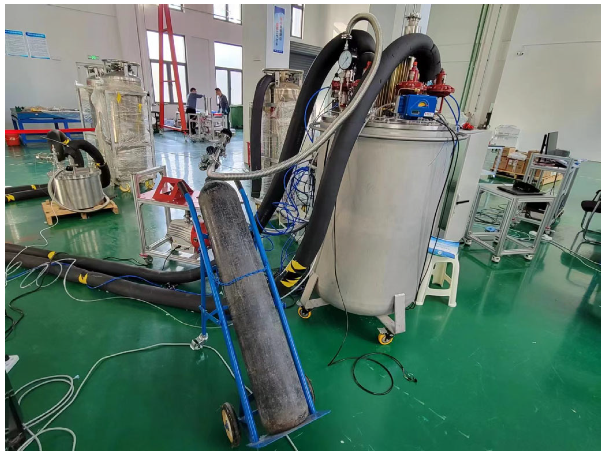
Figure 9.
Liquid nitrogen supply and return temperatures of liquid nitrogen for normal operation of liquid nitrogen cooling circulating units.
Figure 9.
Liquid nitrogen supply and return temperatures of liquid nitrogen for normal operation of liquid nitrogen cooling circulating units.

Figure 10.
Liquid supply temperature and cooling power at different circulating flow rates.


Table 1.
Key parameters of liquid nitrogen cycle units.
| No. | Parameter Name | Design Requirements |
|---|---|---|
| 1 | Operating temperature | 5~35 °C |
| 2 | Pump operating frequency | 20~80 Hz |
| 3 | Closed-loop pressure | 2~10 bar |
| 4 | Pressure stability | ≤1 mbar (rms) (at 5 bar) |
| 5 | Liquid nitrogen storage capacity | ≥200 L |
| 6 | Cooling power | 600 W |
| 7 | Flow rate | 0~10 L/min |
| 8 | Outlet temperature | 77 K |
Table 2.
Physical parameters of nickel–chromium heating wire.
| Name | Technical Specifications and Parameters of Nickel–Chromium Heaters |
|---|---|
| Resistance value | 33.2 Ohms/meter (4.2 K) |
| 33.4 Ohms/meter (77 K) | |
| 34 Ohms/meter (305 K) | |
| Long | 100 (30.5 m) Reel. |
| Insulating material | Polyimide, allowable operating temperature: 493 K |
| Rating | Maximum operating temperature: 425 K. Maximum current: 2.0 A |
Disclaimer/Publisher’s Note: The statements, opinions and data contained in all publications are solely those of the individual author(s) and contributor(s) and not of MDPI and/or the editor(s). MDPI and/or the editor(s) disclaim responsibility for any injury to people or property resulting from any ideas, methods, instructions or products referred to in the content. |
© 2024 by the authors. Licensee MDPI, Basel, Switzerland. This article is an open access article distributed under the terms and conditions of the Creative Commons Attribution (CC BY) license (https://creativecommons.org/licenses/by/4.0/).
Share and Cite
MDPI and ACS Style
Yao, J.; Lu, X.; Xie, Y.; Wang, Q.; Liu, X. A Liquid Nitrogen Cooling Circulation Unit: Its Design and a Performance Study. Machines 2024, 12, 271. https://doi.org/10.3390/machines12040271
AMA Style
Yao J, Lu X, Xie Y, Wang Q, Liu X. A Liquid Nitrogen Cooling Circulation Unit: Its Design and a Performance Study. Machines. 2024; 12(4):271. https://doi.org/10.3390/machines12040271
Chicago/Turabian StyleYao, Jianjie, Xiangyou Lu, Yuanlai Xie, Qianxu Wang, and Xiao Liu. 2024. "A Liquid Nitrogen Cooling Circulation Unit: Its Design and a Performance Study" Machines 12, no. 4: 271. https://doi.org/10.3390/machines12040271
Note that from the first issue of 2016, this journal uses article numbers instead of page numbers. See further details here.