Design Procedure for High-Speed PM Motors Aided by Optimization Algorithms


Department of Electrical and Information Engineering, Politecnico di Bari, 70126 Bari, Italy
*
Author to whom correspondence should be addressed.
Machines 2018, 6(1), 5; https://doi.org/10.3390/machines6010005
Submission received: 30 December 2017
/
Revised: 2 February 2018
/
Accepted: 8 February 2018
/
Published: 11 February 2018
(This article belongs to the Special Issue High Speed Motors and Drives: Design, Challenges and Applications)
Abstract
:This paper considers the electromagnetic and structural co-design of superficial permanent magnet synchronous machines for high-speed applications, with the aid of a Pareto optimization procedure. The aim of this work is to present a design procedure for the afore-mentioned machines that relies on the combined used of optimization algorithms and finite element analysis. The proposed approach allows easy analysis of the results and a lowering of the computational burden. The proposed design method is presented through a practical example starting from the specifications of an aeronautical actuator. The design procedure is based on static finite element simulations for electromagnetic analysis and on analytical formulas for structural design. The final results are validated through detailed transient finite element analysis to verify both electromagnetic and structural performance. The step-by-step presentation of the proposed design methodology allows the reader to easily adapt it to different specifications. Finally, a comparison between a distributed-winding (24 slots) and a concentrated-winding (6 slots) machine is presented demonstrating the advantages of the former winding arrangement for high-speed applications.
1. Introduction
In several application areas, there is a growing interest in high-speed electrical machines [1], because they allow compactness and reliability. For example, direct-drive high-speed actuators permit the elimination of the need for a mechanical gearbox, reducing system weight and increasing its efficiency [2]. As the rotational speed of the electrical machine grows, structural integrity of the rotor tends to become a critical issue [3]. Moreover, core loss quickly grows with the electrical frequency that is proportional to the mechanical speed, resulting in an augmented thermal stress. Among the variety of high-speed brushless machines, Surface Permanent Magnet (SPM) synchronous machines exhibit the highest torque density but also the highest cost, due to rare earth permanent magnets (PMs). Moreover, a retaining sleeve is mandatory in SPM machines, to withstand centrifugal stress and ensure rotor integrity [4,5].
So far, several kinds of optimized design procedures of permanent magnet machines have been presented in the literature, each addressing a particular issue related to this topic (i.e., computational time, optimal solution reliability, integrated mechanical-electromagnetic design, etc.).
In [6] a viable automatic design procedure to enlarge the high-efficiency operation area while keeping low computational burden is proposed. In fact, the finite element method (FEM) is highly time-consuming, above all when efficiency calculations are performed, while the coarse-mesh FEM is a basic technique allowing a reduction of the computational burden through a limited number of elements of the mesh. The combined use of such a method together with Genetic Algorithms (GA) can further reduce the amount of time to design motors with a wider high-efficiency operation area. Meanwhile, in [7] the presented design flow for permanent magnet synchronous machines allows for shorter design time because of the reduced number of iterations. In fact, the design process is organized into nine steps. At each step, calculations can be carried out through electromagnetic, thermal and structural analyses in order to set constraints for the size. Such constraints represent the starting point for the subsequent steps, and FEM analysis can be used for a more detailed investigation. Another sequential design procedure, meant for the interior permanent magnet synchronous generator (IPMSG) of a range-extended electric vehicle (REEV), is presented in [8]. The sequential procedure puts together different design methods and tries to solve the related issues. To address the multi-objective problem (i.e., optimal values of torque amplitude, torque ripple, and cogging torque) in the first step the Taguchi Method is adopted, which allows a sub-optimal solution to be carried out. The second step is based on the Surrogate Assisted GA (SAGA), which provides the optimal solution with higher performance compared to conventional multi-objective optimization algorithms. In order to match the performances of the calculated optimal solution with the experimental tests, in the final stage of the proposed procedure, the issue of the design variable uncertainties is addressed and an improvement of the optimal solution reliability is achieved.
In addition to this interest in a more computational aspect, other authors have focused their attention on the issues related to integrated electromagnetic and mechanical design procedures in case of SPM synchronous machines meant for high-speed applications. In fact, in [9] the proposed design of high-speed permanent magnet synchronous machines relies on a combined electromagnetic and mechanical analysis. The stator structure and the sleeve are designed using FEM, trying to keep the rotor eddy current losses as low as possible. For this purpose, a more detailed technique to estimate iron losses taking into account the effects of harmonics and rotational magnetic flux is proposed. Also, [10] proposes an integrated mechanical-EM design procedure for high-speed SPM synchronous machines in order to get the sleeve thickness, the PM thickness, the shaft diameter, and the interference fit between the PMs and the sleeve. In particular, three high-strength materials for the sleeve are considered and their performances are compared. The proposed method carries out, through FEM, the strength and EM limits and hence the optimal solution for the rotor size is achieved.
Finally, some authors have presented design procedures aimed at lowering the cost of PM synchronous machines. For example, an optimization of the multi-physics design procedure aimed at reducing the system total cost by taking into consideration also the cost and the losses of the power converter is proposed in [11]. Therefore, the presented technique defines the phase angle of the generator current that minimizes the above-mentioned quantities.
Given this background, the main objective of this work is to present an integrated design procedure of both the structural (i.e., sleeve thickness) and the electromagnetic part (i.e., iron and copper dimensions) of a SPM synchronous machine featuring a minimal permanent magnet quantity. The electromagnetic and structural aspects have reciprocal influence throughout the design procedure. In fact, the thinner the magnetic airgap of the machine, the higher the air-gap flux density, and hence the higher the achievable torque and power densities. However, the higher the operational speed, the higher the required thickness of the sleeve to withstand the centrifugal forces exerted by the PMs. As a consequence, a compromise is needed in the design phase to find the best tradeoff between structural reliability and electromagnetic performance. By doing so it will be possible to find the permanent machine configuration with the lowest cost by fulfilling the considered requirements coming from a case study of an aeronautical actuator. Additionally, this paper investigates whether the combined use of a Pareto optimization algorithm and finite element analysis, in the design of high-speed electrical machines, can provide easily analyzable results with an acceptable computational burden. Hence, the presented design procedure utilizes a mix of analytical formulas and finite element magneto-static analysis aided by the optimization algorithm. The procedure is organized in consecutive steps, each performed with relatively fast optimization and run with the aim of reducing the time needed to perform the design optimization and obtaining results that are easy to be analyzed and understood. The validity of the results has been confirmed using detailed transient analysis using finite element software. As a design example, two possible solutions, both with a 4-pole rotor for a high-speed aeronautical actuator have been evaluated. The choice of a low pole number has been made to keep the machine fundamental frequency as low as possible since the motor is designed for high-speed operation. The performance of a distributed winding (DW) machine with 24 slots and a concentrated winding (CW) machine with 6 slots is presented with the aim of assessing which arrangement turns out to be the most suitable for such application. For each winding configuration, the minimal-complexity criterion has been adopted when selecting the number of slots.
2. Design of High-Speed Electrical Machines
The design of the high-speed electrical machine is a multi-physical engineering problem in which electromagnetic, thermal and mechanical aspects must be considered at the same time, being equally important with respect to the final machine performance. Even if the design procedure presented in this paper is mainly focused on electromagnetic aspects, both the loss distribution and the centrifugal stress inside the rotor must be considered in order to obtain reliable and feasible results.
The proposed design procedure is based on the use of FEM software called FEMM, capable of solving magneto-static problems [12]. The FEM software is coupled with an optimization algorithm to automatically select the best stator and rotor geometry, minimizing a given cost function. The setting of the optimization algorithm and the connection with FEMM is guaranteed by a series of scripts written in MATLAB language and distributed within the open-source suite SyR-e [13]. SyR-e was initially developed to apply an optimization algorithm to the design of synchronous reluctance machines, and currently also includes surface-mounted PM machines. As it regards the thermal behavior, the SyR-e software can predict the steady state copper temperature using a lumped parameter model and automatically adjusts the stator current of the electrical machines to maintain constant the Joule losses. The software also includes some analytical formulas for calculating the thickness of the sleeve used to contain centrifugal force, as will be described below.
2.1. Motor Parameterization
Among the parameters that most affect the performances of PM machines, there are the motor volume, the slot/pole combination, and the current density. In this work we will make some preliminary analytical calculations to estimate the motor volume, defined by the length of the lamination stack and the outer stator diameter. Regarding the stator slots, higher numbers usually guarantee a reduced harmonic content in the stator magneto-motive force, and this can have a beneficial effect in reducing iron losses. On the other hand, a reduced slot number together with a tooth-wound winding simplifies the machine manufacturing with positive effects on the length of end-turns and on the Joule losses. The number of poles should be kept low to limit electrical frequency in high-speed applications. In principle, slot and pole numbers could be included among the parameters to be selected by the optimization algorithm. Such a choice would make both the parameterization of motor geometry (e.g., the limits of the geometric parameters are related to the slot/pole combination) and the search problem itself much more complicated. As a rule of thumb, with population-based search algorithms, the size of the population should exceed more than ten times the number of parameters to be optimized. Having in mind the objective of limiting the computational cost, the slot/pole combination has been selected a-priori. In particular, two sets of optimization runs will be presented considering machines with distributed windings, 24 slots and four poles and machines with concentrated windings, six slots and four poles. Regarding the current density, it was selected to keep constant the ratio kj between the stator Joule losses and the outer-stator stack surface. This value, expressed in kW/m2, provides information about how much the machine is thermally and electrically loaded, and usually ranges from 3 kW/m2, for naturally cooled machines, up to 30 kW/m2, for liquid cooled machines. During the optimization process, for each machine to be evaluated, the stator resistance is estimated first. Consequently, the desired kj value determines the rated current that produces the fixed stator Joule losses. This current value is used in the FE analysis to calculate motor performance. Therefore, during a single optimization run, all the machines will be evaluated, keeping constant Joule losses.
The main geometrical parameters describing stator and rotor geometry, namely the tooth width (tw) and length (tl), the rotor radius (r) and PM thickness (lPM) as described in Figure 1, are the parameters selected by the optimization algorithm. In the following, there will be cases in which the PM quantity will be not fixed but only bounded. In such cases, the PM angular span will be fixed and equal to 150 electrical degrees and the PM quantity will vary with the PM thickness between a minimum and a maximum value. In some other optimization run, the PM quantity will be fixed, then the optimization algorithm will still select the PM thickness, but its angular span will be modified so to maintain the PM quantity constant.
2.2. Automatic Calculation of Retaining Sleeve Thickness
To contain the centrifugal forces acting on PMs, a retaining sleeve has been considered. For each machine to be evaluated, the thickness of the sleeve has been estimated using the following procedure.
In order to properly select the sleeve thickness, the overall tangential stress (the so-called hoop stress) acting on the sleeve has to be calculated and the sleeve thickness has to be selected to ensure that the total hoop stress does not exceed the yield stress limit of the sleeve material.
The total hoop stress acting on the retaining sleeve is due to three effects, namely the centrifugal force exerted by the magnets during the rotation, the inertial stress due to the sleeve mass itself, and the stress due to the rotor-shaft cylinder.
Manufacturing tolerances, thermal deformation and interference fit for rotor parts fastening should be considered before manufacturing for a proper dimensioning. We decided to neglect such phenomena during initial sleeve sizing because the main aim here is to have an approximate but simple estimation of the sleeve thickness to predict its impact on machine electromagnetic performances.
The centrifugal stress on the sleeve due to the magnets can be calculated as:
where is the centrifugal force due to the magnets, ( is the PM number, is the mass of each magnet, and is the maximum rotating speed of the machine), and are the radii of the mass centers of magnets and sleeve respectively, is the PM length in the axial direction, and is the sleeve thickness in the radial direction.
The inertial stress due to the sleeve mass itself has, again, a centrifugal nature, i.e., it is proportional to the square of the speed. With the assumption of the sleeve thickness being much smaller than the diameter, the inertial stress of the sleeve can be calculated as
with being the specific density of the sleeve material.
The total stress on the sleeve due to the rotor-shaft part is composed of three contributions: the centrifugal stress due to the iron mass (); the shear stress (), which is proportional to the torque; and the tangential stress generated by the mechanical interference of the rotor-shaft coupling (). The latter depends on the minimum interference that is required to ensure the torque transmission from the rotor of the machine to the shaft, which has been calculated to avoid slipping between the parts during motion. The resulting hoop stresses have been then increased considering the mechanical tolerances and the effect of temperature. To evaluate the resulting hoop stress on the sleeve, the equivalent Von Mises stress has been calculated as
The total Von Mises stress has been referred to as the sleeve radius and compared with the two aforementioned contributions from the PMs and from the sleeve itself.
As stated above, the total hoop stress on the sleeve is the sum of the three contributions. Since the contribution from the rotor-shaft part is much lower than the other two, with the aim of finding a closed-form expression for the sleeve dimensioning, the detailed calculations of the rotor hoop stress have been neglected. An increased security factor has been employed, in order to reduce the risk of a bandage failure as presented in [14]. By imposing the total sleeve hoop stress () to be less than the yield stress of the material () divided by the security factor
the sleeve thickness is given by:
In (5), is the radius of the rotor comprising the sleeve, and the rotor axial length.
2.3. Preliminary Analitical Sizing
A preliminary analytical design stage is performed in order to select the machine outer volume (stator diameter and axial length) and an initial estimate of stator and rotor geometry useful to define the search space of the optimization algorithm. The procedure is based on the calculation of the expected torque and power factor as a function of two parameters. The first parameter is the ratio between the magnet thickness () and the sum of the sleeve thickness () and the actual airgap () . The second parameter is the split ratio between stator and rotor diameters (x). In order to estimate both power factor and torque, it is possible to calculate, for each couple (b, x), the airgap magnetic flux density, the d-axis stator flux, and the stator inductances [15]. The preliminary design procedure is integrated within the SyR-e software, and is based on a linearized magnetic model of the machine. At the end of the preliminary design procedure, the software returns the torque and power factor values in the x-b plane. The designer will then select an x-b couple that will be used as the starting point for the optimization procedure. Although simple, this approach is usually accurate enough to have an initial estimate of the machine geometry to be used as a starting point for the optimization process. This will be much more reliable than analytical sizing because it will be based on FE simulations.
2.4. FEA Verification of the Analytical Mechanical Model
The sleeve sizing based on analytical formulas has been verified through a centrifugal FE analysis by employing ANSYS software. For the sake of brevity, Figure 2 only reports the results referred to as Mot242, since comparable results were obtained with the other rotors. The maximum stress is below 300 MPa, and well agrees with the value considered during the analytical design stage. The titanium alloy considered in this study has a yield strength equal to 840 MPa, and the safety factor is equal to three. The displacements of the sleeve could be reduced by filling up the space among the magnets with a material whose coefficient of thermal expansion is close to the magnet material properties [14]. A verification of the required interference among rotor parts in the whole speed and temperature range would complete the rotor design. This is omitted here because the main aim is to compare the electromagnetic potential of different machine configurations ensuring comparable mechanical performances, as verified with the analysis presented in Figure 2.
3. Optimization Algorithm
Optimization algorithms are widely used in many engineering applications to aid designers in finding the solution that maximizes or minimizes some performance or cost indexes [16]. Numerous applications of optimization algorithms can be found in recent literature, and also in the field of electrical machine design [17]. A detailed description of the theory behind the optimization algorithms is behind the scope of this paper. In this section, some general concepts will be reviewed so as to give the essential definitions useful in the following sections. Optimization algorithms can be divided into deterministic and stochastic algorithms. In the latter case, some random variables appear in the phase of performance evaluation or in the algorithm iterative procedure. They are well established as an effective tool to solve complex optimization problems. The stochastic algorithm usually starts with the random selection of a number of potential solutions, also called population of individuals, within a predefined search space. These individuals are usually represented as a set of real numbers (genes). They are iteratively modified on the basis of their performance indexes and using stochastic rules often inspires a mechanism related to natural evolution.
The performances of each optimization algorithm are strictly related to the algorithm settings and to the characteristics of the specific optimization problem. Here we will consider the Differential Evolution (DE) algorithm that is a good compromise between complexity and effectiveness [18], but the results shown in the following could be replicated with almost any population-based stochastic algorithm. The familiarity of the designer with the algorithm settings is often more useful than the actual performances of the optimization algorithm.
3.1. Pareto Optimization Algorithm
It is quite common in many optimization problems to have two or more conflicting design objectives. They could be aggregated using a weighted sum in a single objective but in this way one objective could tend to be predominant in the selection of the optimal solution. A more effective approach to cope with multi-objective problems introduces the concept of dominance and ranks the solutions in Pareto fronts. In the following we will consider two-objective optimization problems where cost1 and cost2 are the performance indexes (cost function) to be minimized. Solution A dominates another solution B when both cost1 and cost2 are lower for solution A (see Figure 3a). Within a population it is possible to find a sub-set of solutions that are not dominated by any other solution. This sub-set is called the Pareto front of non-dominate solutions (see Figure 3a). All the solutions in the Pareto front are ranked 1 and are equally good. The designer will have to select the most favorable solution in the Pareto front deciding how much to favor one cost function and penalize the other. Once the Pareto front solutions are removed from the population, it is possible to define a second Pareto front among the remaining individuals, which will be ranked 2. The ranking mechanism is illustrated in Figure 3c. In order to avoid solutions too similar to each other in the Pareto front, the Manhattan distance is calculated among the Pareto front individuals (see Figure 3d). The ones with higher distance with respect to the other solutions are favored to remain in the population at the next algorithm iteration. The algorithm is iterated a predefined number of times. The final Pareto front individuals are the optimal ones that will be displayed to help the designer in the selection of a single solution. The best compromise between competitive cost functions can only be a human choice.
3.2. Selection of Objective Functions
Although it would be useful to have many contemporary objectives, each additional objective implies a considerable increase of computational cost. This is due to the fact that the algorithm must produce a consistent Pareto front that contains an adequate number of solutions. For example, moving from a two-objective problem to a three-objective problem, Pareto front changes from a line (which is usually well described by a few dozen solutions) to a plane in a three-dimensional space that requires at least a hundred solutions to be correctly represented. When the number of objectives exceeds three, the Pareto front becomes difficult to visualize and the solutions required in order to properly analyze the problem grow even more. Having many solutions on the Pareto front requires the use of algorithms with very large populations that require more time to be analyzed and converge to suitable solutions.
For these reasons, it is generally preferred to limit the optimization objectives to not more than three. In this paper, only two-objective optimizations will be considered, leading to easily readable Pareto fronts as lines in the two-objective plane. One of the two objectives will always be the electromagnetic torque since the maximization of the torque density is the main objective of the electromagnetic design considered here. As a second objective, the torque ripple, or the quantity of permanent magnet or the power factor, could be considered. It will be shown later which combinations of objectives are the most appropriate for the design of high-speed electric machines. Design procedures based on a series of two-objective optimizations will be presented, which allow finding solutions of adequate overall quality in relatively short times. The design procedure allows the reduction of copper and PM quantity within the limits imposed by the respect of the design specifications. The torque maximization is pursued at constant Joule losses, and the maximization of torque per Joule losses ratio inherently improves efficiency.
4. Design Problem Statement
As a design example, a high-speed actuator for aeronautic applications is considered. Required continuous power is 50 kW at a base speed of 50,000 rpm, and the maximum overload power is equal to 75 kW. Some preliminary calculations based on analytical formulas allowed definition of the stator diameter, equal to 90 mm and the active axial length of the machine equal to 120 mm. Adopting a kj index of about 30 kW/m2 gives, in this case, a value of admitted Joule losses of about 1kW. The copper over-temperature with respect to the cooling water is estimated equal to 60 °C using a lumped parameter thermal network.
The airgap thickness is initially set equal to 0.5 mm. After electromagnetic design, the shaft, bearings and housing must be designed so to be compatible with this airgap value considering the vibration modes of the shaft. This part of final mechanical design, although critical for the final prototype feasibility, is beyond the scope of this paper and will not be considered further on.
Regarding the stator and rotor iron laminations, low-loss steel with high silicon content was preferred (10JNEX900 manufactured from JFE steel). This choice allows the limitation of iron losses, especially in high-frequency electrical machines, and, for this reason, it is preferred here with respect to standard silicon iron or cobalt iron alloys [19].
The pole pairs number has been chosen equal to 2 so to limit the base frequency at 1667 Hz at 50,000 rpm. Two pole/slot combinations have been considered to compare the performances that could be obtained using distributed and concentrated windings. In particular, a 24-slot stator and a 6-slot stator have been coupled in turn with a 4-pole rotor. In the case of the 24-slot stator a single layer of distributed winding has been considered with 2 slots per pole per phase and no chording. In the case of the 6-slot stator the winding is a double layer with 0.5 slots per pole per phase. The main design specification obtained after preliminary design are listed in Table 1.
4.1. Settings for the Optimization Algorithm
As mentioned earlier, the population size and the number of allowed iterations must be set in order to run a population-based optimization algorithm. The population size has been selected ten times higher than the number of genes (parameters to be optimized) while the maximum number of iterations was 1.25 times the population size. Since the parameters to be optimized are four (namely tooth width and length, rotor radius and PM thickness) 40 individuals are iterated for 50 generations at each optimization run.
The search space limits adopted for 24- and 6-slot machines are summarized in Table 2. When both rotor radius and tooth length are close to their upper limit, if a minimum thickness to the stator yoke is not guaranteed (i.e., 5 mm), the tooth length is automatically reduced. It is important that the optimization algorithm checks for the feasibility of each machine before calling the FE software so as to avoid it crashing prematurely and aborting the optimization run.
4.2. Optimization Procedure
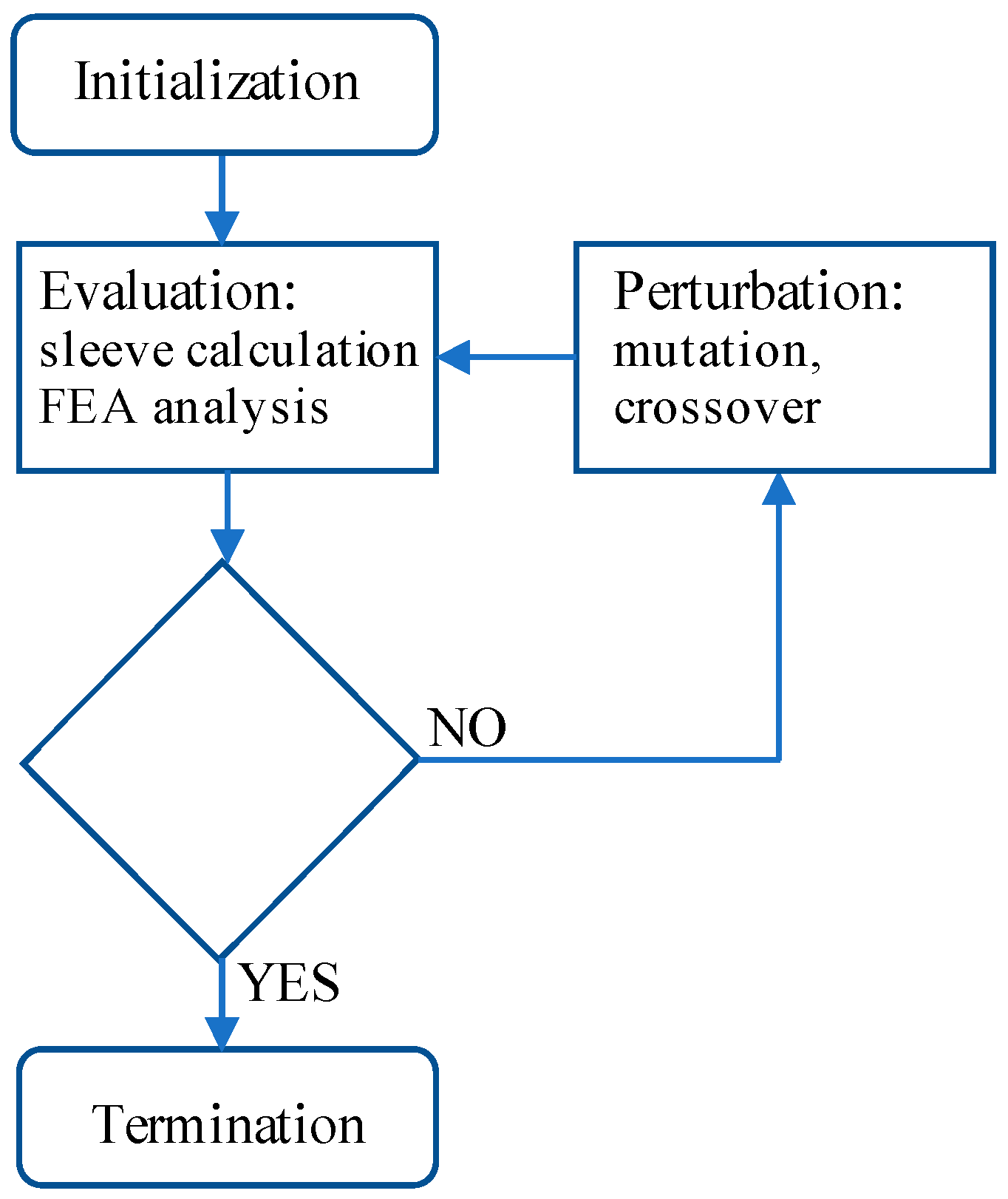
The procedure to perform the multi-objective optimization of each machine design follows the typical steps of initialization, evaluation and perturbation. The initial population is randomly selected within the search space defined in Table 2 (initialization). Then each individual is evaluated with a two-step procedure. At first, the sleeve thickness is calculated on the basis of the specific parameters of each individual (mainly rotor radius and PM quantity) according to Equation (5), then the electromagnetic performance (torque, torque ripple, internal power factor) is calculated by means of a FEA simulation using FEMM. The solutions are then ranked according to the Pareto criterion, and this ends the evaluation step. Then, the mutation and crossover operators described in [20] are applied to the current population (perturbation) so as to pass the next population to the evaluation step. This perturbation and evaluation procedure is repeated 50 times (number of generations) then the optimization is terminated and the final Pareto front is given as a result of the design procedure. Figure 4 shows a flow-chart of the proposed iterative method for the multi-physics design procedure.
5. Results
In this section, the results obtained after the optimization run are presented. Each run considers two objectives at the time; one of them is the average torque and the second objective is in turn the torque peak-to-peak ripple, the magnet quantity and the internal power factor. Hereinafter they will be referred as T/∆T, T/PM and T/IPF run respectively. The PM quantity will be evidenced using the section area of a single magnet, measured in mm2 (all the considered machines have four magnets and an axial length of 120 mm). The internal power factor is defined as the cosine of the phase angle between the back-electromotive force and the stator current. In the case of surface-mounted PM machines, when the current is commanded in quadrature to the PM flux linkage, the internal power factor can be defined as in (6):
where and are the d- and q-axis flux linkages. The calculation of the IPF is preferred here because it does not need the knowledge of motor losses, which are difficult to estimate using magnetostatic FE software (e.g., iron and sleeve losses), but are representative of the final power factor (PF). Machines with higher IPF will generally have higher PF.
5.1. 24-slot Machine
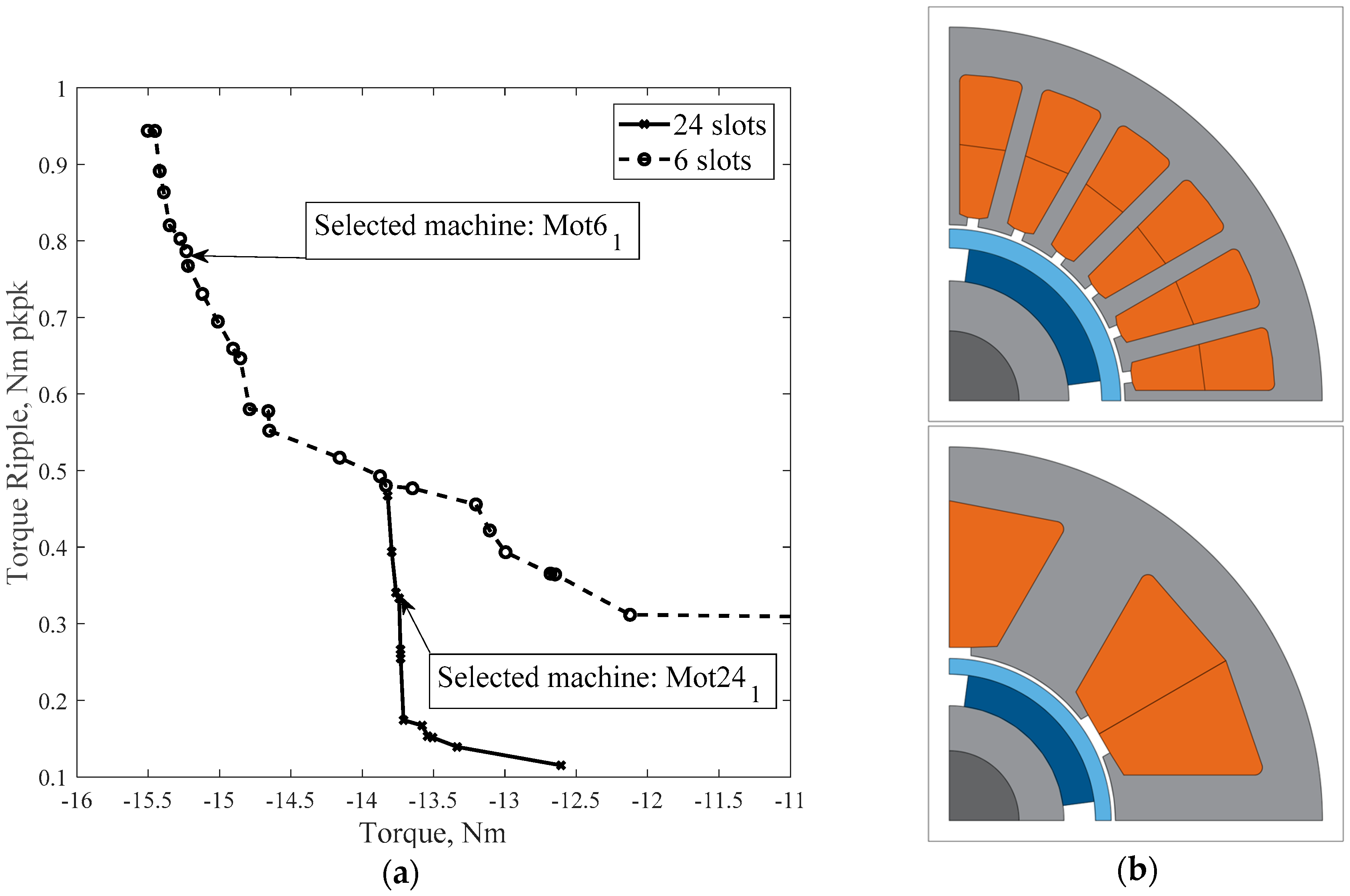
The first run was a T/∆T optimization and the obtained Pareto front is reported in Figure 5. This Pareto front denotes the low sensitivity of the torque with respect to the torque ripple in case of 24-slot machines. The two goals are not very competing, meaning that sacrificing one of them (e.g. increasing the torque ripple) does not bring clear advantages for the other objective (e.g., the average value of the torque). All the machines of the Pareto front have very low torque ripple (below 5% of the average torque), and similar geometrical and performance characteristics. Within the Pareto front machines, the ones with the larger amount of magnet realize a torque of about 13.7 Nm and a power factor equal to just below 0.8 (see the selected machine Mot241 shown in Figure 5). This T/∆T optimization run provides useful and interesting information. The Pareto front machines have similar amounts of magnet beyond which the increase of the thickness of the sleeve would penalize the performances in terms of electromagnetic torque. The optimization algorithm has been able to choose the amount of magnet to produce the maximum torque. If the PM quantity were further increased, the thickness of the sleeve, which must hold greater centrifugal forces, would also increase, resulting in lower average torque values. The search algorithm finds the best combination of magnet quantity and airgap radius to maximize torque. The PM quantity of the machines belonging to the Pareto front is close to 350 mm2.
Another interesting result is the IPF value, which appears to be limited at 0.8. Increasing the IPF would penalize the average torque value as it could be verified via a T/IPF optimization run.
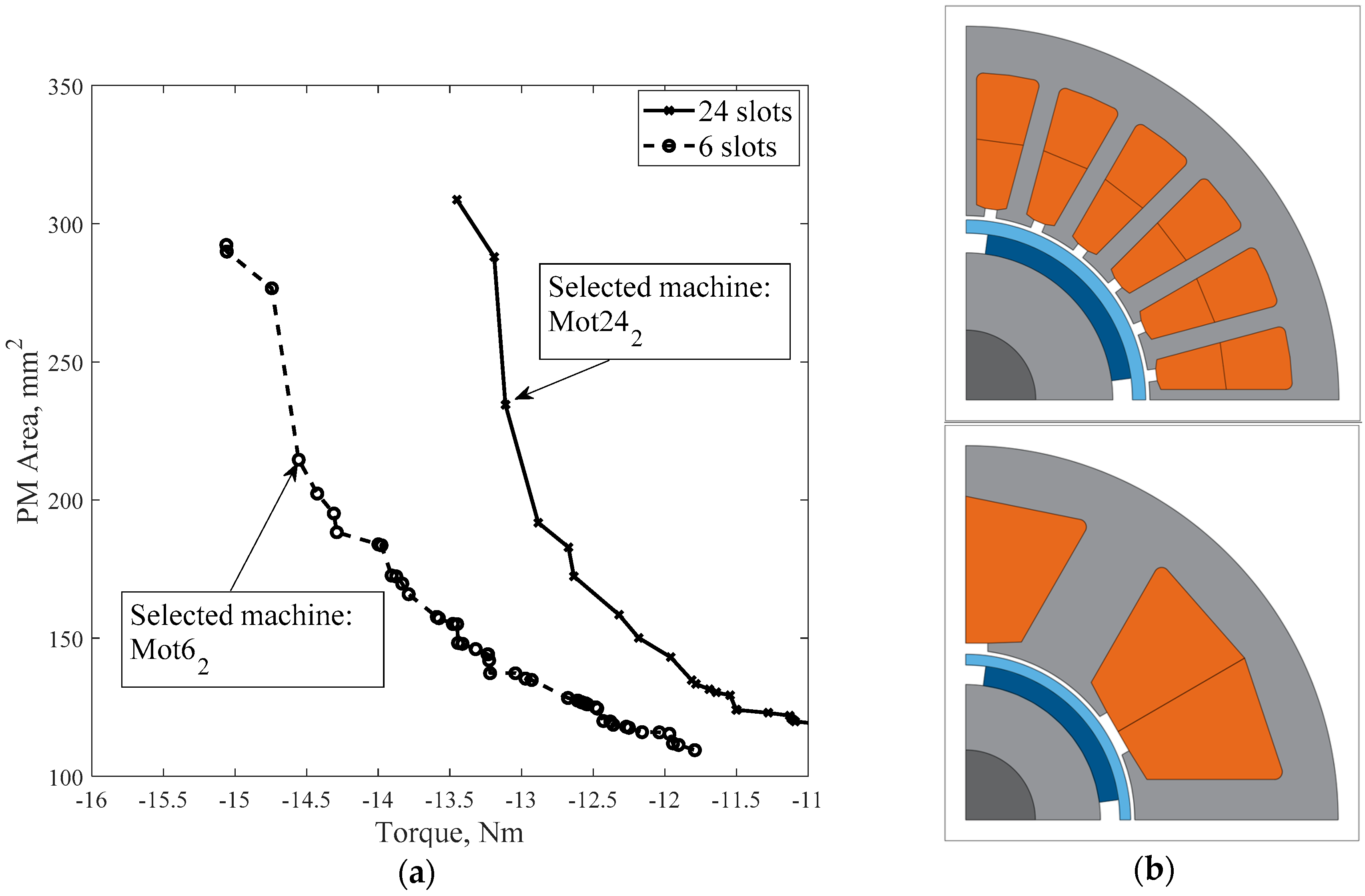
To evaluate the possibility of reducing the PM quantity, a second optimization run is performed considering T/PM as objective functions. Unlike the previous case, one can see from the Pareto front in Figure 6 that the PM quantity and torque are objectives in strong competition: sacrificing one of them brings clear benefits to the other objective. The machines that produce the largest torque on the Pareto front also have the largest amount of magnet and this is very close to the amount of magnet of the machines optimized in the previous T/∆T run (i.e., 350 mm2). This further demonstrates the existence of a maximum amount of magnet beyond which the high-speed machine has no benefits in terms of torque. By analyzing the individual machines of the Pareto front in Figure 6, it is possible to verify that there is a direct link between the quantity of magnet and the IPF. Machines with a greater quantity of magnet in Figure 6 have an IPF of about 0.8; if the quantity of magnet goes down to 235 mm2 the IPF is reduced to 0.7 (i.e., the selected Mot242 machine shown in Figure 6). This value of IPF is considered to be the minimum limit that should not be exceeded downwards in order not to pay too much in terms of power electronic converter size.
To verify the possibility of improving the power factor of the selected Mot242 by means of geometrical modifications while keeping the same amount of PM, it is possible to perform another optimization run. This new run uses the torque and internal power factor (T/IPF) as targets, and puts a constraint on the quantity of PM material. The constraint on the quantity of permanent magnet has been realized leaving the optimization algorithm free to choose the radial thickness of the magnet and consequently adapting the angular span β of the magnet according to (7):
where and are the external and internal magnet radii, respectively.
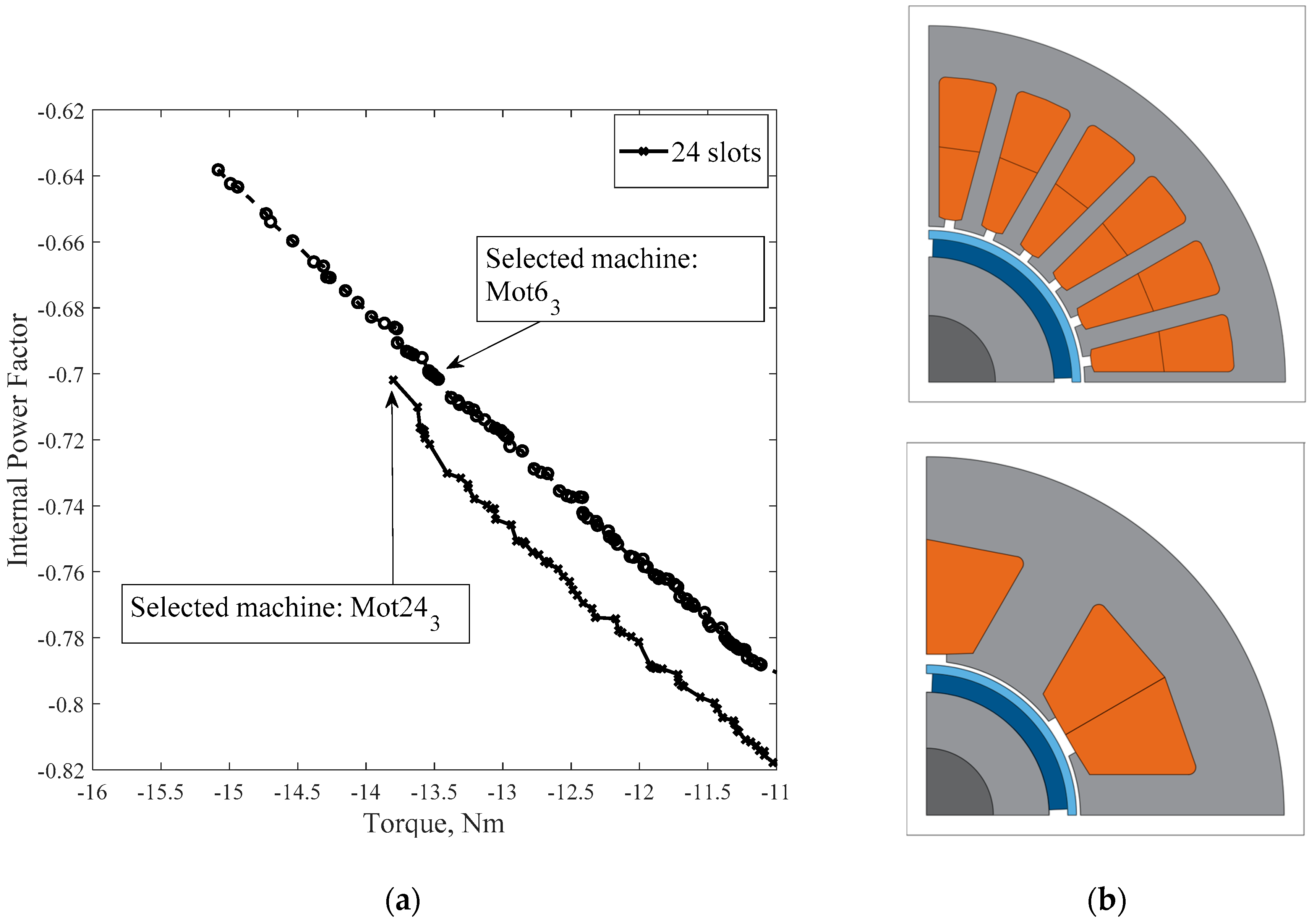
The Pareto front in Figure 7 has been obtained with a T/IPF run with fixed PM quantity equal to 230 mm2. It is possible to notice that this Pareto front is almost a straight line when the quantity of magnet is constrained and only its angular span is modified. In general, machines with higher power factor in the T/IPF Pareto front have reduced slot area and more generous iron paths into the stator. Considering the performance of Mot242, selected after the T/PM run, it would be placed very close to the Pareto front of the T/IPF optimization run. A considerable improvement of the power factor would require accepting a reduced average torque, and at the same power factor level, the improvement of torque is not very relevant. In conclusion, machine Mot242 will be the selected design for the 24-slot machines, further analyzed in the next section to verify their performances.
5.2. 6-slot Machine
The same design procedure described for the 24-slot machine can be applied to 6-slot, 4-pole machines with tooth-wound coils. Potentially, such machines may have an advantage in terms of weight and losses due to the reduced length of the end windings and higher filling factors for the copper area within the slots. The slot-filling factor considered for the 6-slot designs is 0.5, while it was limited to 0.4 for the 24-slot machines. Particular care must be used during the electromagnetic design to limit torque pulsations and losses.
Initially, a T/∆T run has been executed and the results are shown in Figure 5. In the case of CW machines, the reduction of torque ripple can be obtained only at the expenses of torque. In this case, is not simple to find a combination of stator and rotor geometry that gives a low torque ripple comparable to that of DW machines. Nevertheless, also in the case of CW machines, torque ripple is relatively small, and always below 10% of average torque for Pareto front machines. All the machines in the Pareto front shown in Figure 5 have a PM area larger than 300 mm2, and the maximum values for the electromagnetic torque are higher than the analogous results obtained with DW machines, mainly because of the higher current density. It is important to remark that all the FE analysis considers the same amount of Joule losses. CW machines, thanks to the higher copper-filling factor, have a reduced resistance and can tolerate higher current to slot area ratio. Power factor is generally lower in the CW machines. On average, a 10% reduction of power factor has been found in the Pareto front machines, moving from a CW to a DW machine at the same torque level.
In order to understand the relationship between PM quantity and maximum torque reachable by the CW machines, a T/PM run has been executed and the results are shown in Figure 6. In this case, the Pareto fronts have very similar shape, with a torque advantage of DW machines about 10%, again related to the 25% advantage given by the filling factor. The selected machine Mot62 has a PM quantity similar to the machine Mot242 selected on the analogous Pareto front among 24-slot solutions and a torque 11% higher. Again, the power factor of the CW machine is lower than DW machines and only reaches 0.6 for machine Mot62. Also the torque oscillations are higher in CW machines, in the case of the selected machines Mot62 the torque ripple equals 1Nm, while it is about 30% lower for Mot242.
To improve the power factor, without increasing the PM quantity, also in this case another optimization run can be executed using torque and power factor as objective functions. As in case of 24-slot machines, the PM quantity was fixed to 230 mm2. The obtained results are shown in Figure 7. The maximum torque that can be achieved with an internal power factor at least equal to 0.7 is about 13.5 Nm. This is the case of the selected machine Mot63 that will be the final design among the 6-slot solutions. It is important to notice that, despite the filling factor advantage of CW machines, their torque produced with the same magnet quantity and at the same power factor is a few percent lower than DW machines.
The multi-step procedure used in this work consists of three two-objective optimization runs (T/∆T, T/PM and T/IPF). Among the three Pareto fronts it is usually possible to select the best solution to mediate among conflicting objectives. Of course, this multi-step procedure increases the computational cost compared to a single two-objective run but is much less demanding than a three-objective run that would be required to simultaneously consider the three objectives (i.e., T/PM/IPF).
6. Validation of the Results and Discussion
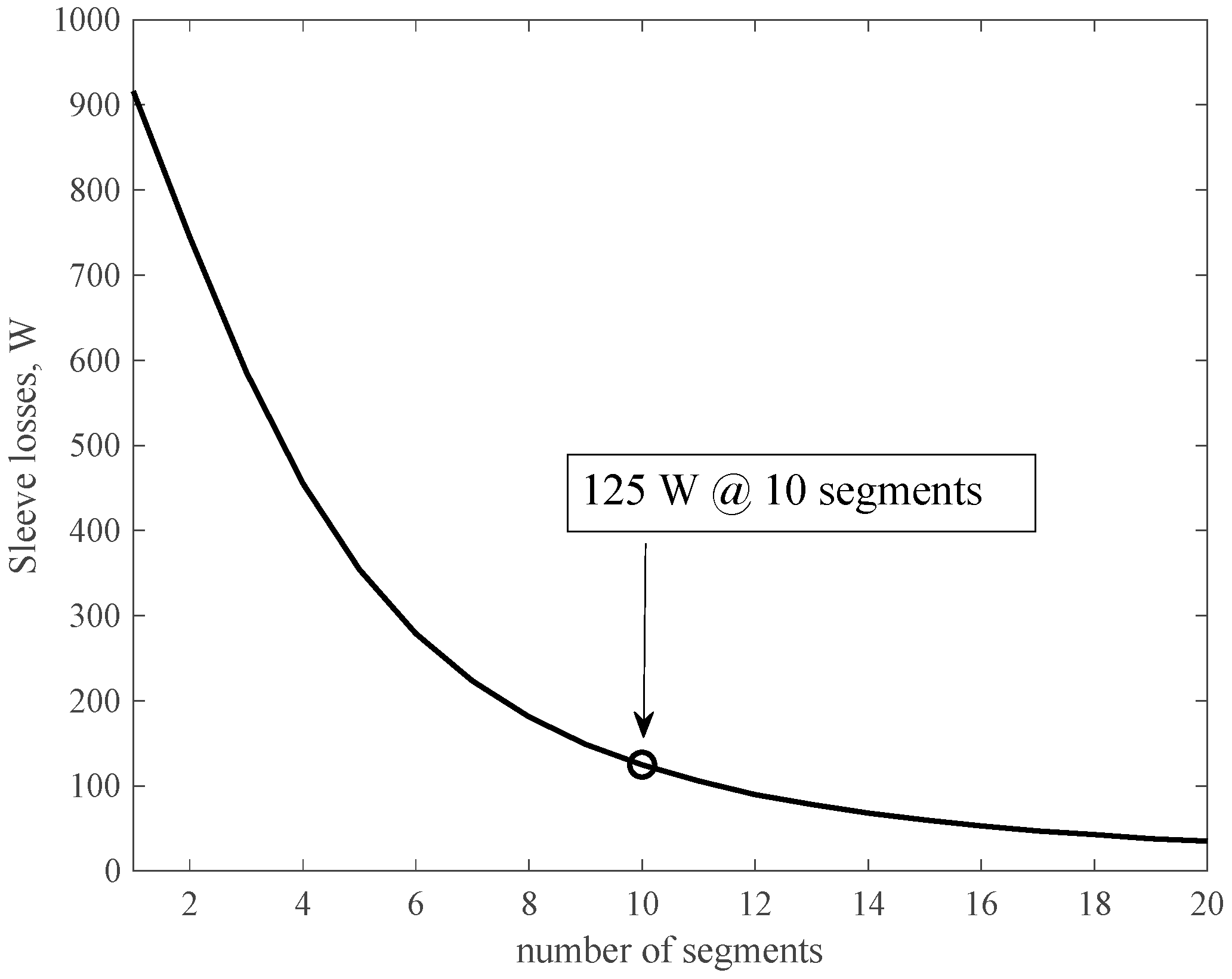
The machines designed and selected in the previous section, namely Mot242 and Mot63, have been analyzed using transient finite element software to validate the results. In principle, it would be possible to use the same transient analysis also during the optimization stage, but this would increase the computational burden by more than an order of magnitude. The results shown next will confirm the feasibility of the proposed design method. Since all the optimized machines exceed the required target torque, in order to make a fair comparison of the performance, the stator current of each machine was reduced until the resulting mechanical torque approximately equals 10 Nm. In the loss analysis emerges the need to limit the sleeve losses due to the induced parasitic current. Among the most commonly used solutions to mitigate the sleeve losses there is the segmentation of the sleeve, which can be divided in a number of rings electrically isolated from each other so as to obtain an effect similar to the lamination of iron core. The same segmentation will be adopted for the PMs so as to simplify the rotor manufacturing process and limit magnet losses as well. Thanks to the segmentation and to the shielding effect of the conducting sleeve, the losses into the magnets and rotor iron will be negligible. The losses into the sleeve, considering the segmentation, can be calculated starting from a 2D analysis (performed in our case using Magnet software [21]) and considering the theory presented in [22]. The sleeve losses are approximated by the following formula
where are the sleeve losses obtained neglecting the tangential paths of the parasitic currents, is the number of pole pairs, and is the axial length of a single sleeve section and D is its diameter. Figure 8 reports the sleeve losses as a function of the number of sections in the case of motor Mot242. They are about 1 kW without segmentation and drop below 150 W using ten segments. Similar curves are obtained also for the 6-slot machines, but in this case the sleeve losses are much higher. They are about six times higher for Mot63. In order to obtain sleeve losses lower than 200 W for the 6-slot machines, the number of sleeve sections should exceed 20. In Table 3 the reported losses have been calculated considering 10 sleeve sections for all the machines. Restricting the loss analysis to copper and iron losses, CW machines have a small advantage, quantified at about 100 W, which would give a 0.2% improvement in terms of efficiency. Adding the sleeve losses, there is a clear advantage of DW machines that would be maintained even if the number of sleeve sections for the DW machine were reduced to three.
Of course, it could be possible to reduce the sleeve losses of the 6-slot machines carefully considering their slot opening. Considering machine Mot63 with the slot closed using magnetic wedges, it is possible to calculate a 25% reduction of sleeve losses with a negligible torque loss. This would make the performances of DW and CW machines closer, but there would still be an advantage of DW machines in terms of overall efficiency.
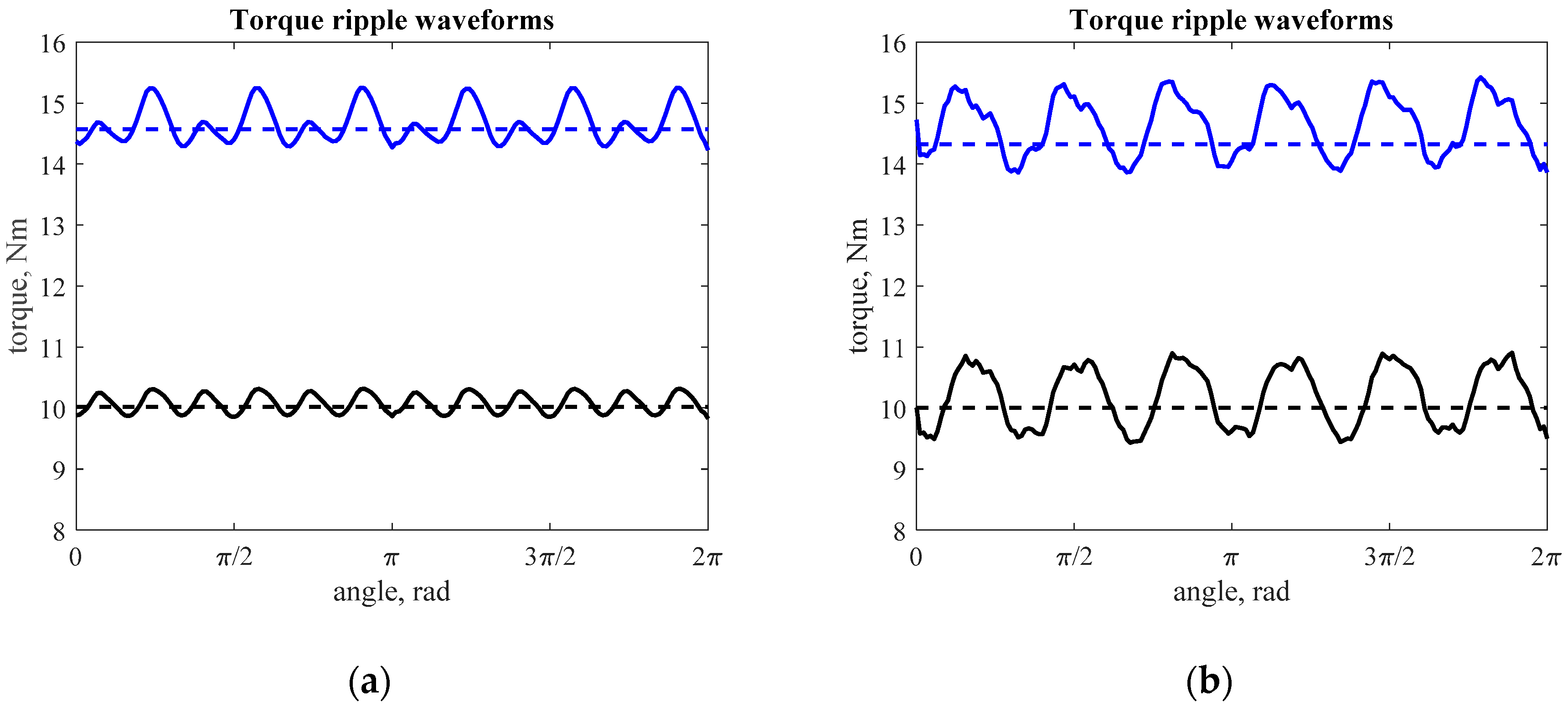
Figure 9 reports the torque waveforms of the selected machines at rated and overload conditions calculated using transient FE analysis. The DW machine presents a reduced torque ripple, confirming the analysis performed using static FE during the optimization phase. The peak-to-peak torque ripple of Mot63 is about 15% the rated torque. The higher torque ripple of Mot63 is a drawback of the CW configuration, and it is due to the higher harmonic content of the back-EMF with respect to the DW and to the wider slot opening as a consequence of the lower number of slots. Also, in this case, a careful design of the slot opening could improve the performance of CW machine, but it would be unlikely to have a better torque ripple of DW Mot242 machine.
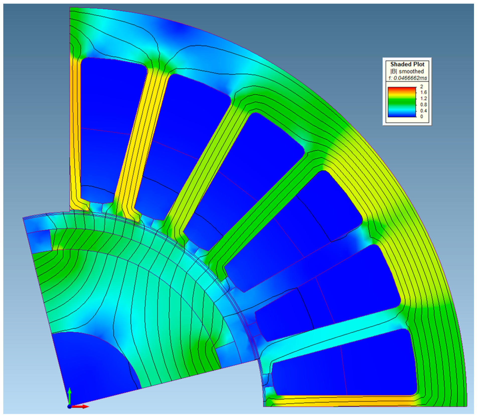
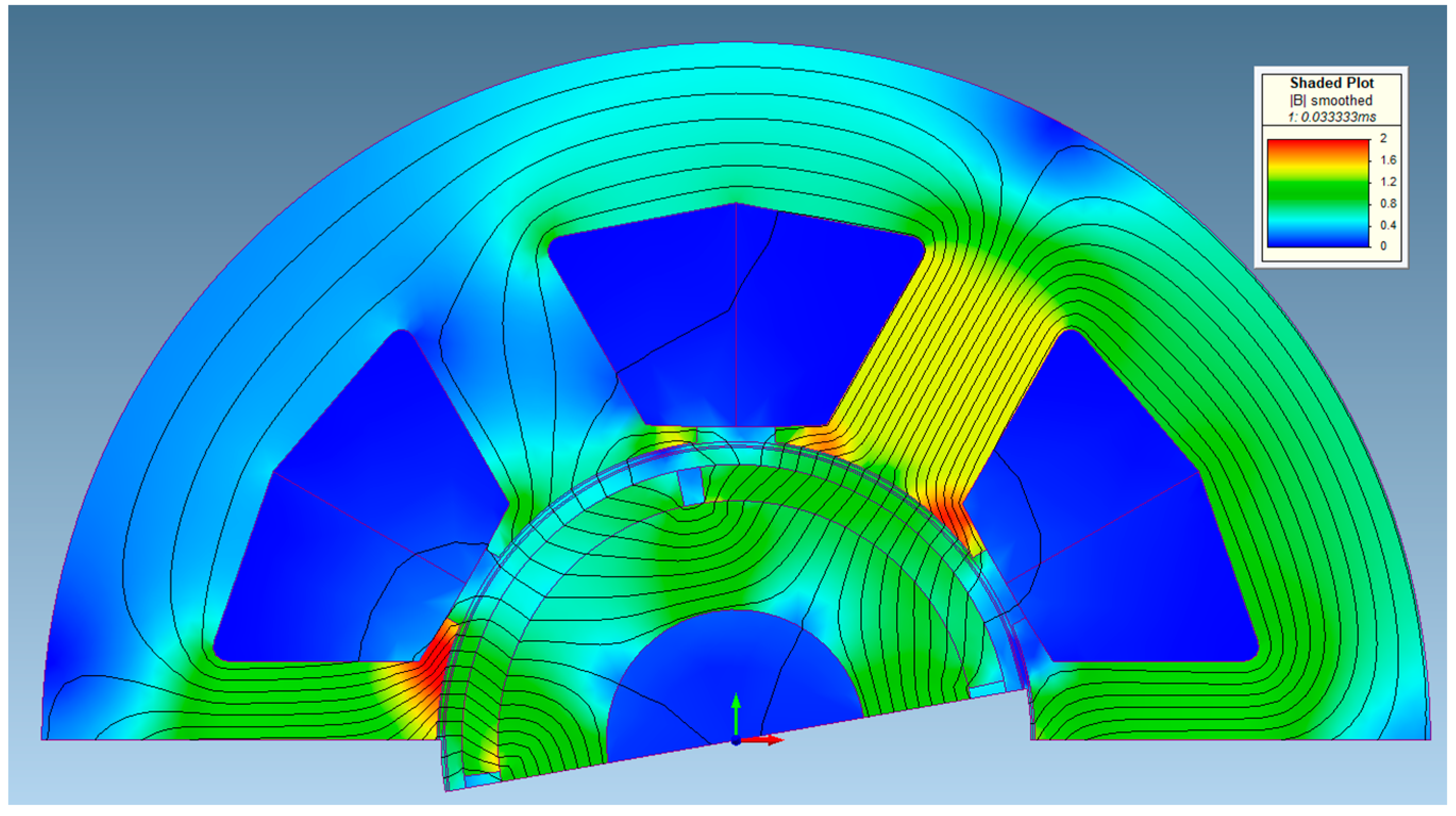
The flux density contour and distribution of the two selected motors (Mot63 and Mot242) at rated condition are shown in Figure 10 and Figure 11, respectively. The effective magnetic air gap that the magnetic circuit has to face in both cases comprehends the sleeve thickness addressing the mechanical issues, thus the air-gap flux density is lower than in an ideal case (i.e., null sleeve thickness).
7. Conclusions
In this paper, an electromagnetic and structural co-design procedure for high-speed synchronous permanent magnet machines is presented considering requirements coming from an aeronautical actuator. The proposed design procedure relies on optimization algorithms coupled with finite element analysis. In particular, only two-objective optimizations have been considered, aiming at finding solutions of adequate overall quality in relatively short times and, additionally, easily readable Pareto fronts as lines in the two-objective plane. Therefore, the overall optimization problem has been divided into three two-objective optimization runs (i.e., Torque/Torque Ripple, Torque/Magnet Quantity and Torque/Internal Power Factor). The proposed multi-step procedure is much less demanding, from a computational point of view, than a single three-objective run, which would be required to simultaneously consider the three objectives. In addition to these computational advantages, the design procedure features a reduction of the copper and PM quantity according to the design requirement limits, and the extraction of the maximum torque is achieved by keeping constant the Joule losses.
In order to fulfill the design requirements, two possible configurations (i.e., distributed- and concentrated-winding machines) have been designed through the proposed multi-step procedure, whose outcomes have been validated through detailed transient finite element analysis to verify both electromagnetic and structural performances. Results show that, in case of an equal number of sleeve sections, the distributed-winding machine performs better than the concentrated-winding one both in terms of efficiency and of torque ripple for such high-speed applications.
Acknowledgments
This work was supported in part by the Italian Ministry of University and Research under Grant PON03PE_00067_8 “MEA: Gestione Ibrida dell’Energia per applicazioni aeronautiche”.
Author Contributions
The authors equally contributed to this article in terms of conceiving, theoretical analysis, numerical simulations, paper writing.
Conflicts of Interest
The authors declare no conflict of interest.
References
- Rahman, M.A.; Chiba, A.; Fukao, T. Super high speed electrical machines—Summary. In Proceedings of the IEEE Power Engineering Society General Meeting, Denver, CO, USA, 6–10 June 2004; Volume 2, pp. 1272–1275. [Google Scholar]
- Gerada, D.; Mebarki, A.; Brown, N.L.; Gerada, C.; Cavagnino, A.; Boglietti, A. High-Speed Electrical Machines: Technologies, Trends, and Developments. IEEE Trans. Ind. Electron. 2014, 61, 2946–2959. [Google Scholar] [CrossRef]
- Borisavljevic, A.; Polinder, H.; Ferreira, J.A. On the Speed Limits of Permanent-Magnet Machines. IEEE Trans. Ind. Electron. 2010, 57, 220–227. [Google Scholar] [CrossRef]
- Binder, A.; Schneider, T.; Klohr, M. Fixation of buried and surface-mounted magnets in high-speed permanent-magnet synchronous machines. IEEE Trans. Ind. Appl. 2006, 42, 1031–1037. [Google Scholar] [CrossRef]
- Krahenbuhl, D.; Zwyssig, C.; Weser, H.; Kolar, J.W. A Miniature 500,000-r/min Electrically Driven Turbocompressor. IEEE Trans. Ind. Appl. 2010, 46, 2459–2466. [Google Scholar] [CrossRef]
- Nakata, T.; Sanada, M.; Morimoto, S.; Inoue, Y. Automatic design of IPMSMs using a genetic algorithm combined with the coarse-mesh finite element method for enlarging the high-efficiency operation area. IEEE Trans. Ind. Electron. 2017, 64, 9721–9728. [Google Scholar] [CrossRef]
- Uzhegov, N.; Kurvinen, E.; Nerg, J.; Pyrhönen, J.; Sopanen, J.T.; Shirinskii, S. Multidisciplinary Design Process of a 6-Slot 2-Pole High-Speed Permanent-Magnet Synchronous Machine. IEEE Trans. Ind. Electron. 2016, 63, 784–795. [Google Scholar] [CrossRef]
- Lim, D.K.; Jung, S.Y.; Yi, K.P.; Jung, H.K. A novel sequential-stage optimization strategy for an interior permanent magnet synchronous generator design. IEEE Trans. Ind. Electron. 2018, 65, 1781–1790. [Google Scholar] [CrossRef]
- Zhang, Y.; McLoone, S.; Cao, W.; Qiu, F.; Gerada, C. Power Loss and Thermal Analysis of a MW High-Speed Permanent Magnet Synchronous Machine. IEEE Trans. Energy Convers. 2017, 32, 1468–1478. [Google Scholar] [CrossRef]
- Fang, H.; Qu, R.; Li, J.; Zheng, P.; Fan, X. Rotor Design for High-Speed High-Power Permanent-Magnet Synchronous Machines. IEEE Trans. Ind. Appl. 2017, 53, 3411–3419. [Google Scholar] [CrossRef]
- De Paula Machado Bazzo, T.; Kölzer, J.F.; Carlson, R.; Wurtz, F.; Gerbaud, L. Multiphysics design optimization of a permanent magnet synchronous generator. IEEE Trans. Ind. Electron. 2017, 64, 9815–9823. [Google Scholar] [CrossRef]
- Finite Element Method Magnetics. Available online: http://www.femm.info/wiki/HomePage (accessed on 25 December 2017).
- Syre—Synchronous Reluctance (Machines) Evolution. Available online: http://sourceforge.net/projects/syr-e/ (accessed on 25 December 2017).
- Lahne, H.C.; Gerling, D.; Staton, D.; Chong, Y.C. Design of a 50,000 rpm high-speed high-power six-phase PMSM for use in aircraft applications. In Proceedings of the Eleventh International Conference on Ecological Vehicles and Renewable Energies (EVER), Monte Carlo, Monaco, 6–8 April 2016. [Google Scholar]
- Lu, C.; Ferrari, S.; Pellegrino, G. Two Design Procedures for PM Synchronous Machines for Electric Powertrains. IEEE Trans. Transp. Electr. 2017, 3, 98–107. [Google Scholar] [CrossRef]
- Goldberg, D.E. Genetic Algorithms in Search, Optimization, and Machine Learning, 1st ed.; Addison-Wesley: Boston, MA, USA, 1989; ISBN 0201157675. [Google Scholar]
- Pellegrino, G.; Jahns, T.M.; Bianchi, N.; Soong, W.; Cupertino, F. Automated design of synchronous reluctance motors. In The Rediscovery of Synchronous Reluctance and Ferrite Permanent Magnet Motors; SpringerBriefs in Electrical and Computer Engineering; Springer: Cham, Switzerland, 2016; Chapter 5; pp. 109–135. [Google Scholar]
- Neri, F.; Tirronen, V. Recent advances in differential evolution: A survey and experimental analysis. Artif. Intell. Rev. 2010, 33, 61–106. [Google Scholar] [CrossRef]
- Palmieri, M.; Perta, M.; Cupertino, F. Design of a 50.000-r/min Synchronous Reluctance Machine for an Aeronautic Diesel Engine Compressor. IEEE Trans. Ind. Appl. 2016, 52, 3831–3838. [Google Scholar] [CrossRef]
- Brest, J.; Greiner, S.; Boskovic, B.; Mernik, M.; Zumer, V. Self- adapting control parameters in differential evolution: A comparative study on numerical benchmark problems. IEEE Trans. Evolut. Comput. 2006, 10, 646–657. [Google Scholar] [CrossRef]
- Infolytica. Available online: http://www.infolytica.com/ (accessed on 25 December 2017).
- Russell, R.L.; Norsworthy, K.H. Eddy currents and wall losses in screened-rotor induction motors. Proc. IEE Part A Power Eng. 1958, 105, 163–175. [Google Scholar] [CrossRef]
Figure 1.
Definition of the main parameters of stator and rotor geometries.
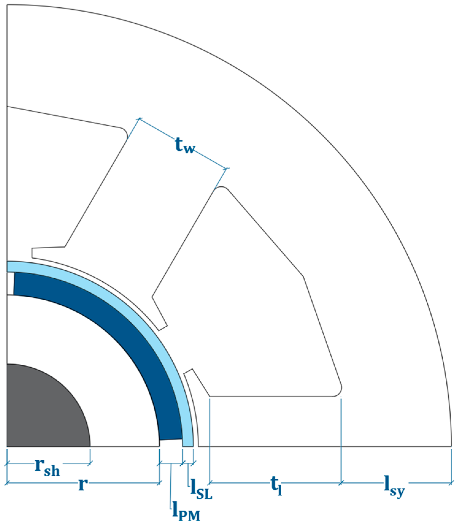
Figure 2.
Radial displacements (a) and Von Mises stresses (b) in the sleeve material at 50,000 rpm.
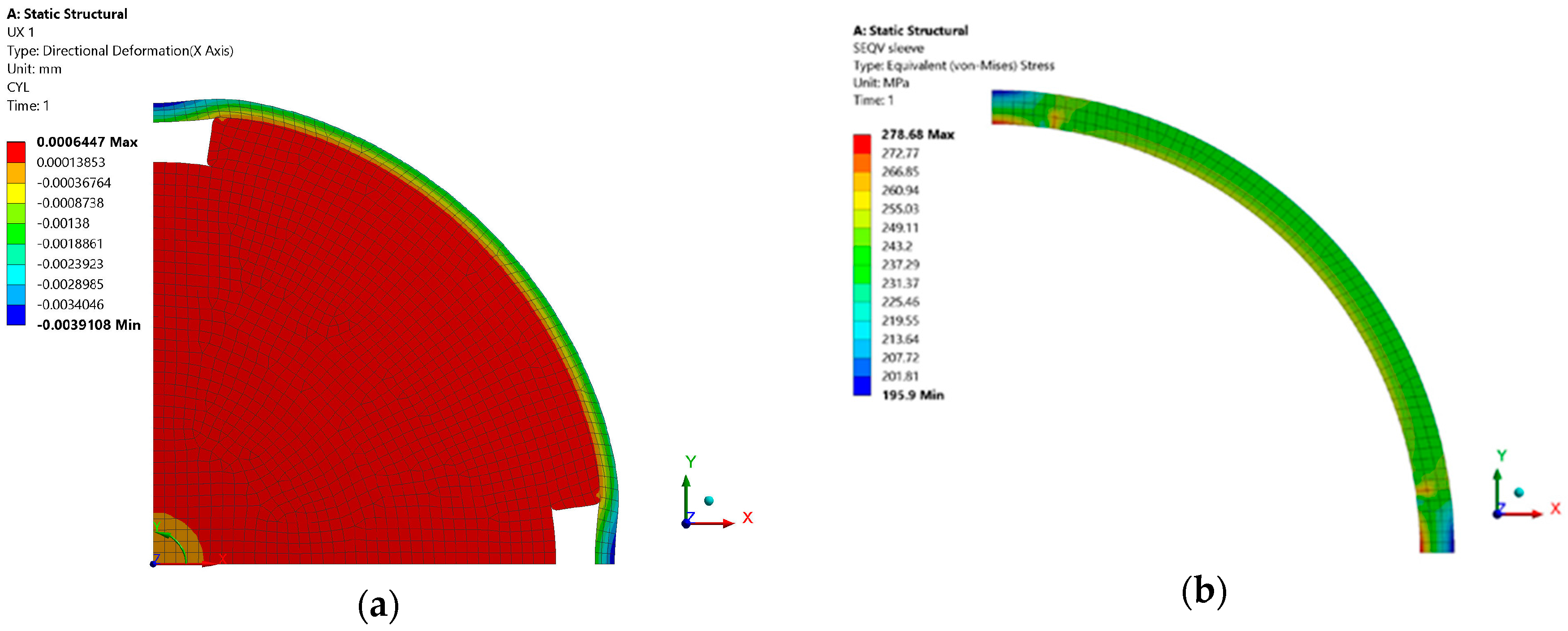
Figure 3.
Definition of (a) dominance criterion, (b) Pareto front, (c) ranking of Pareto fronts, and (d) Manhattan distance for a two-objective minimization problem.
Figure 3.
Definition of (a) dominance criterion, (b) Pareto front, (c) ranking of Pareto fronts, and (d) Manhattan distance for a two-objective minimization problem.
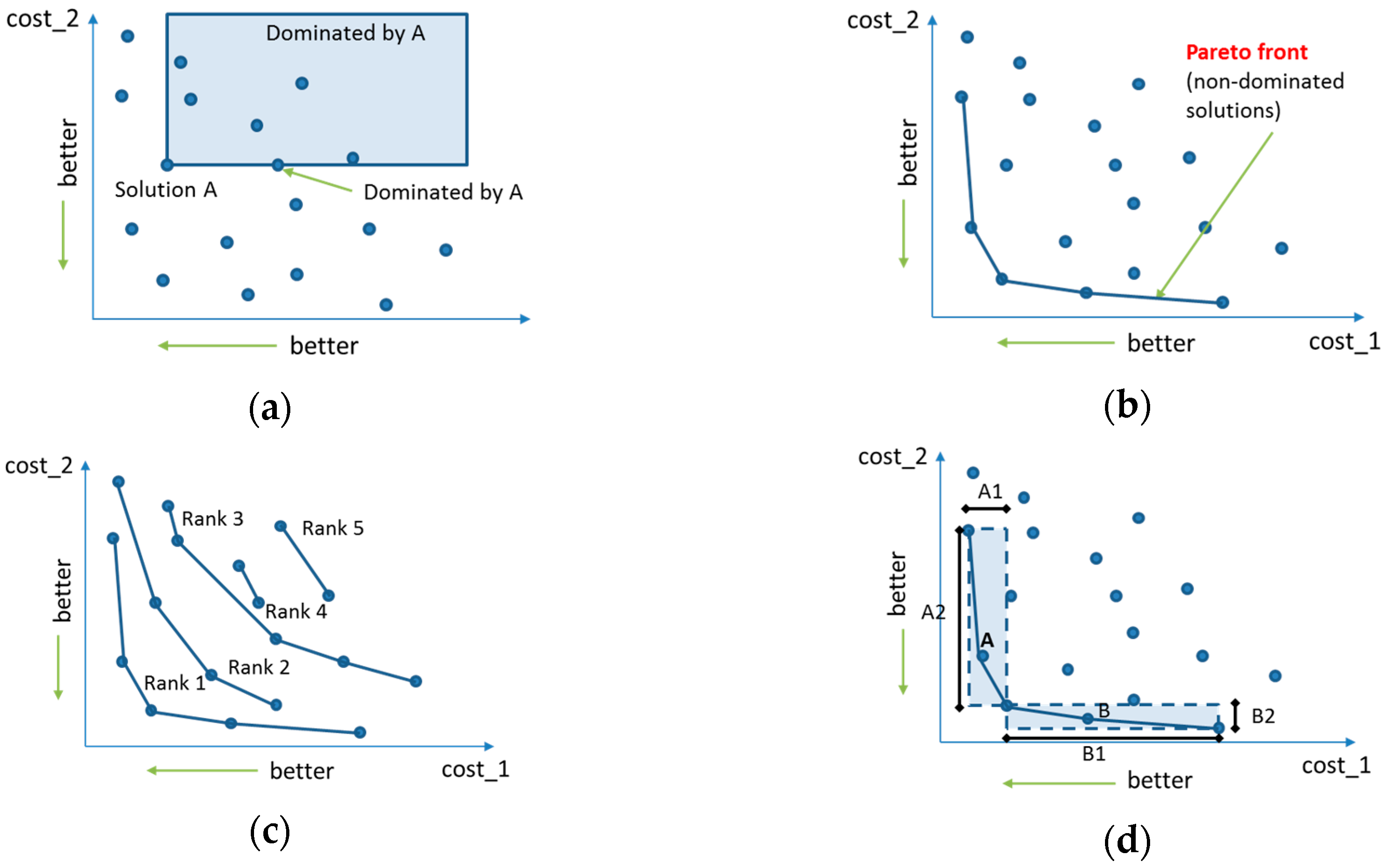
Figure 4.
Flow-chart describing the optimization procedure.

Figure 5.
Pareto front of the T/∆T run (a) and selected 6-and 24-slot machines (b).

Figure 6.
Pareto front of the T/PM run (a) and selected 6-and 24-slot machines (b).

Figure 7.
Pareto front of the T/IPF run (a) and selected 6-and 24-slot machines (b).

Figure 8.
Sleeve losses as a function of the number of segments of the sleeve for Mot242.

Figure 9.
Torque ripple for the DW Mot242 (a) and for the CW Mot63 (b) machines at rated current and 1.5 overload.
Figure 9.
Torque ripple for the DW Mot242 (a) and for the CW Mot63 (b) machines at rated current and 1.5 overload.

Figure 10.
Flux lines and flux density distribution of Mot63 with rated current.

Figure 11.
Flux lines and flux density distribution of Mot242 with rated current.

Table 1.
Main machine specifications obtained after preliminary design.
| Parameter | Value | Units |
|---|---|---|
| Motor type | Surface mounted PM | - |
| Base speed | 50,000 | rpm |
| Continuous power | 50 | kW |
| Overload power | 75 | kW |
| Cooling system | glycol/water 40 °C | |
| Stator radius | 45 | mm |
| Axial length | 120 | mm |
| Airgap | 0.5 | mm |
| Allowed Joule losses | 1000 | W |
| kj, joule losses/external stator surface | 30 | kW/m2 |
| Pole pairs | 2 | - |
| Stator slots | 24 or 6 | - |
| Copper filling factor | 0.4 for 24 slots/0.5 for 6 slots | |
| PM material | NdFeB (BMN-48H-ST) | - |
| Iron material | 10JNEX900 | - |
| Sleeve material | Titanium Alloy | - |
Table 2.
Limits of the search space.
| Parameter | 24-slot Machines | 6-slot Machines |
|---|---|---|
| Rotor radius, mm | [17, 25] | [17, 25] |
| PM thickness, mm | [1.3, 4] | [1.3, 4] |
| Tooth width, mm | [2, 3.5] | [9, 12] |
| Tooth length, mm | [12, 19] | [12, 19] |
Table 3.
Losses and efficiency of the selected optimized machines at rated and overloaded conditions.
Table 3.
Losses and efficiency of the selected optimized machines at rated and overloaded conditions.
| Parameter | Mot242 | Mot63 | Units | ||
|---|---|---|---|---|---|
| Torque | 10 | 14.6 | 10 | 14.3 | Nm |
| Copper losses | 547 | 1240 | 495 | 1120 | W |
| Stator iron losses | 217 | 237 | 173 | 203 | W |
| Iron + Copper losses | 764 | 1477 | 668 | 1323 | W |
| Sleeve losses | 125 | 209 | 764 | 1373 | W |
| Total losses | 889 | 1686 | 1432 | 2696 | W |
| Efficiency | 98.3 | 97.8 | 97.3 | 96.5 | % |
© 2018 by the authors. Licensee MDPI, Basel, Switzerland. This article is an open access article distributed under the terms and conditions of the Creative Commons Attribution (CC BY) license (http://creativecommons.org/licenses/by/4.0/).
Share and Cite
MDPI and ACS Style
Cupertino, F.; Leuzzi, R.; Monopoli, V.G.; Cascella, G.L. Design Procedure for High-Speed PM Motors Aided by Optimization Algorithms. Machines 2018, 6, 5. https://doi.org/10.3390/machines6010005
AMA Style
Cupertino F, Leuzzi R, Monopoli VG, Cascella GL. Design Procedure for High-Speed PM Motors Aided by Optimization Algorithms. Machines. 2018; 6(1):5. https://doi.org/10.3390/machines6010005
Chicago/Turabian StyleCupertino, Francesco, Riccardo Leuzzi, Vito Giuseppe Monopoli, and Giuseppe Leonardo Cascella. 2018. "Design Procedure for High-Speed PM Motors Aided by Optimization Algorithms" Machines 6, no. 1: 5. https://doi.org/10.3390/machines6010005
Note that from the first issue of 2016, this journal uses article numbers instead of page numbers. See further details here.