The Modelling, Simulation and FPGA-Based Implementation for Stepper Motor Wide Range Speed Closed-Loop Drive System Design

Department of Electrical Engineering, National Chin-Yi University of Technology, Taichung 41170, Taiwan
*
Author to whom correspondence should be addressed.
Machines 2018, 6(4), 56; https://doi.org/10.3390/machines6040056
Submission received: 27 August 2018
/
Revised: 12 October 2018
/
Accepted: 22 October 2018
/
Published: 1 November 2018
(This article belongs to the Special Issue High Speed Motors and Drives: Design, Challenges and Applications)
Abstract
:Owing to the benefits of programmable and parallel processing of field programmable gate arrays (FPGAs), they have been widely used for the realization of digital controllers and motor drive systems. Furthermore, they can be used to integrate several functions as an embedded system. In this paper, based on Matrix Laboratory (Matlab)/Simulink and the FPGA chip, we design and implement a stepper motor drive. Generally, motion control systems driven by a stepper motor can be in open-loop or closed-loop form, and pulse generators are used to generate a series of pulse commands, according to the desired acceleration/run/deceleration, in order to the drive system to rotate the motor. In this paper, the speed and position are designed in closed-loop control, and a vector control strategy is applied to the obtained rotor angle to regulate the phase current of the stepper motor to achieve the performance of operating it in low, medium, and high speed situations. The results of simulations and practical experiments based on the FPGA implemented control system are given to show the performances for wide range speed control.
1. Introduction
Stepper motors are adopted in a variety of drive applications because of their high precision of positioning, low costs of the driver, simplicity of operation, and high torque at low speeds. However, stepper motors suffer from some drawbacks such as missed steps, decreased torque at high speeds, resonances, and high power consumption. Speed and position closed-loop and current vector control are good choices to overcome these drawbacks mentioned above.
Regarding closed-loop position control, which usually uses the encoder to compensate for the position error, the end point can be adjusted by commanding additional step pulses to bring the motor back to the correct position. Furthermore, closed-loop control can also operate the stepper motor in microstepping mode, and the accuracy of position can be verified and adjusted dependent on the resolution of the encoder. The control mode of the stepper motor is thus gradually developed into closed-loop control, and adopts a highly efficient controller to achieve better performance [1,2,3] as compared with open-loop control.
Vector control has been widely used in induction motors [4] and permanent magnet synchronous motors (PMSMs) [5,6]. Because of the fact that the hybrid stepper motor is similar to permanent magnet synchronous motors or brushless DC motors in the mechanism of action, the theoretical basis and analysis foundation of the vector control for the stepper motor are also proposed [1,7]. To this end, the vector control strategy is used in the drive system design of the hybrid stepper motor. As the two-phase hybrid stepper motors are different from the conventional three-phase PMSMs or brushless DC motors (BLDCMs), we do not need to construct the functions of − transformations.
As a result of their flexibility and high performance, field programmable gate array (FPGA) has been widely used in hardware controller realization. Some examples include the design of the Proportional-Integral-Derivative (PID) controller [8] and the fuzzy controller [5]. It is also applied in power electronics circuits [9] and drive system designs of PMSMs [5,6,10], induction motors [4], switched reluctance motors [11], and BLDCMs [12]. Furthermore, FPGA is suitable for the development of an embedded system or a system on a chip (SoC), and the developed embedded system can be a part of a complete motion control system.
In this study, we use FPGA in the stepper motor drive system design, and adopt vector control for the regulation of the inner current loop. Furthermore, to get the trapezoidal velocity profile for point to point command, an encoder is used to close the position and velocity control loop. All the hardware circuits are realized by FPGA. The design starts from building the drive system in a Matrix Labaratory (Matlab)/Simulink platform [9], and the software system is simulated on Quartus II and Modelsim [10,13]. The resulting digital hardware system is in the type of Verilog code and is practically implemented on an Altera Cyclone III FPGA. Finally, the developed hardware control system and the power module are applied to a hybrid stepper motor to show the validity and performance.
The contents of the paper are as follows. In Section 2, the experimental setup and system modelling are presented. Then, the simulation results and discussions are given for the built system in Section 3. The experimental results are shown in Section 4. Finally, the conclusions are given in Section 5.
2. The Experimental Setup and Modelling of the Developed Drive System
2.1. The Experimental Setup
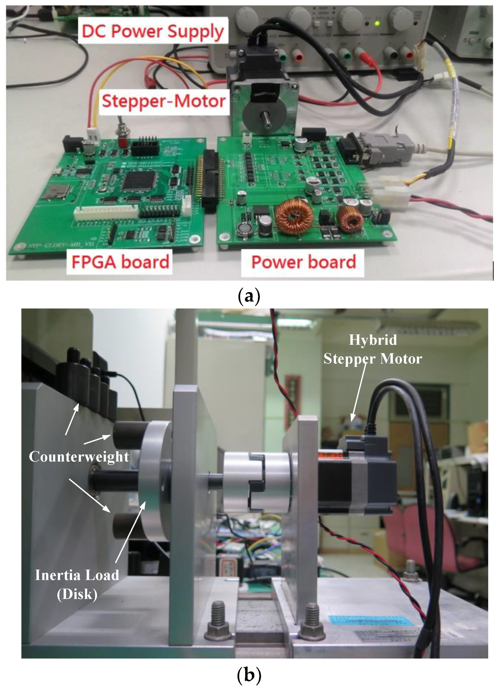
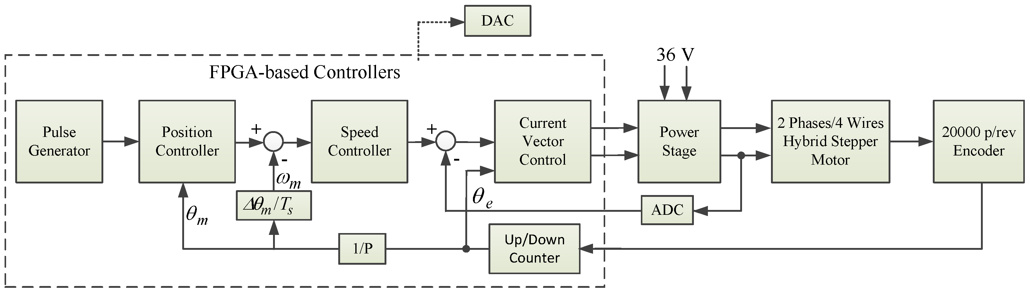
The experimental hardware setup of the proposed system is shown in Figure 1. Figure 1a includes the FPGA-based control board and power module board. In the former, the FPGA IC, analog to digital converters (ADCs), and digital to analog converters (DACs) are shown. In the latter, the main components are two H-bridge circuits and two Hall current sensors. Figure 1a also displays the DC power supply and hybrid stepper motor. In Figure 1b, the experimental motor is fixed and axis-coupled to a disk load where six counterweights can be inserted or removed to change the inertia of the load. The FPGA chip is used to develop the hardware control system, which includes the current regulator, the speed controller, the position controller, and the encoder up/down counter. The encoder counter module accepts the A/B/Z phase pulse signals and outputs the four times precision pulse signal as the position feedback. The position control module is designed to accept the pulse string commands and run the proportional control, which has a sampling frequency of 2 kHz. The four times precision encoder counter module feeds back the accumulated angle to the speed/position controllers to complete the closed-loop control. The sampling frequency for the speed control loop is also set at 2 kHz. The current control loops are based on vector control, and operated at 20 kHz sampling frequency. The main control board also includes two serial ADCs, two serial DACs, and Hall current sensors. The ADCs are used to get the analog current signals of phases A and B detected by Hall current sensors. The DAC is used to output the controlled variables inside the control system, where the variables are intended to be checked and compared. The waveforms of the DACs are shown on the oscilloscope, and they are captured for illustration and comparison. The ADCs are operated at 20 kHz to match the current vector control loop, while the DACs are operated at random by the programming. The stepper motor is a hybrid one with rated current 2A, and the DC bus voltage is 36 V. Furthermore, the stepper motor is equipped with a 20,000 pulses/rev encoder. The contents of the encoder counter are provided for the position and speed feedback, as well as for the coordinate transformation between the stationary reference frame and synchronous rotation reference frame. The block diagram for the proposed system is shown in Figure 2.
2.2. The Modelling of the Stepper Motor
The electrical equations and the generated torque for the two-phase hybrid stepper motor are shown in (1)–(3) [3].
The mechanic equation is as follows:
with the following relation:
For those equations, and are the voltages of phases A and B, respectively; and are the phase currents of phases A and B, respectively; is the resistor; is the inductance; is the torque constant; is the electrical rotor position; is the pole pair; is the generated torque; is the rotor inertia; is the viscous fraction coefficient; is the shaft speed; is the shaft position; and is the fourth harmonic detent torque constant.
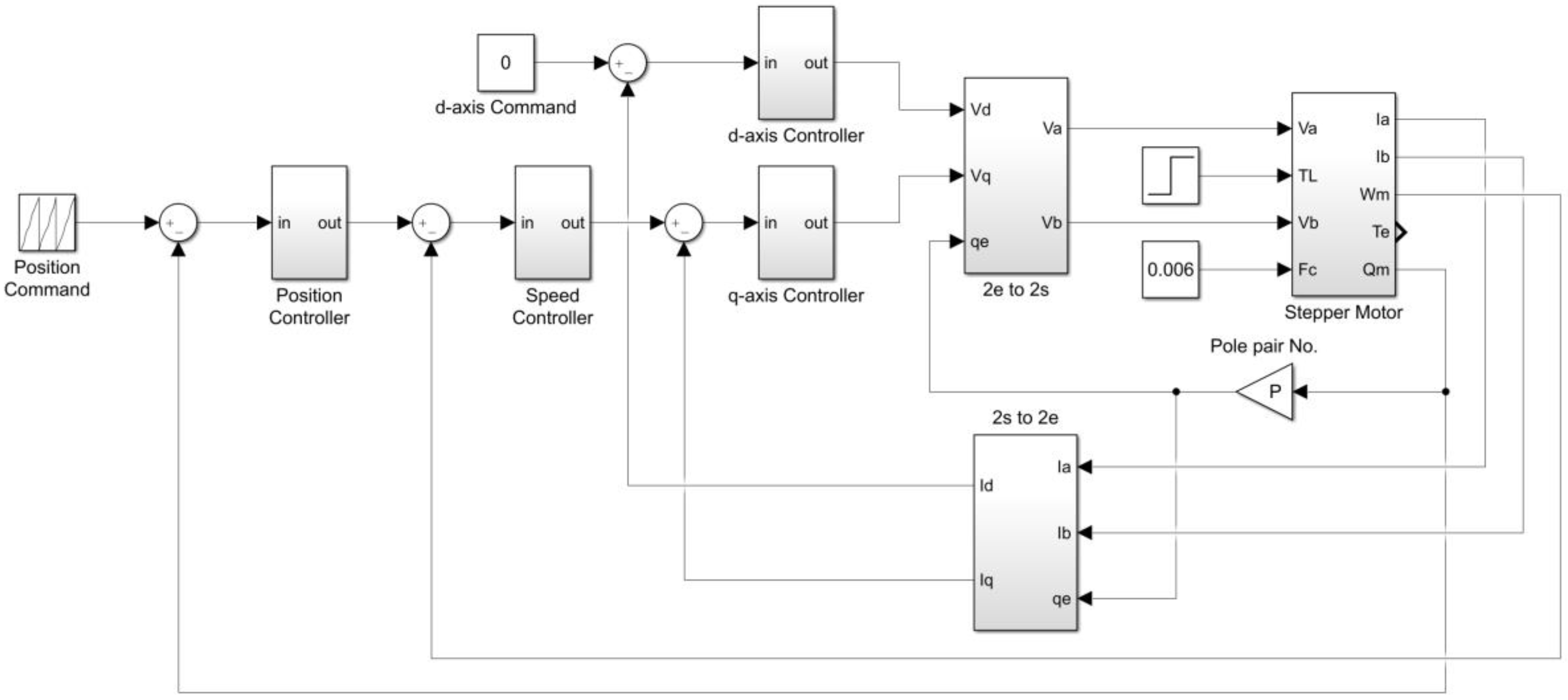
With the modelling of (1)–(5), the block, as shown in Figure 3 and named as “Stepper Motor”, is built using Matlab/Simulink. Furthermore, to realize the current vector control, the coordinate transformation for current between the two-phase stationary reference frame (2s) and two-phase synchronous rotation reference frame (2e) are executed by the blocks of 2s to 2e and 2e to 2s, respectively, and the relations are given by the following:
where a and b are the variables in the stationary reference frame, and d and q are the variables in the synchronous rotation reference frame.
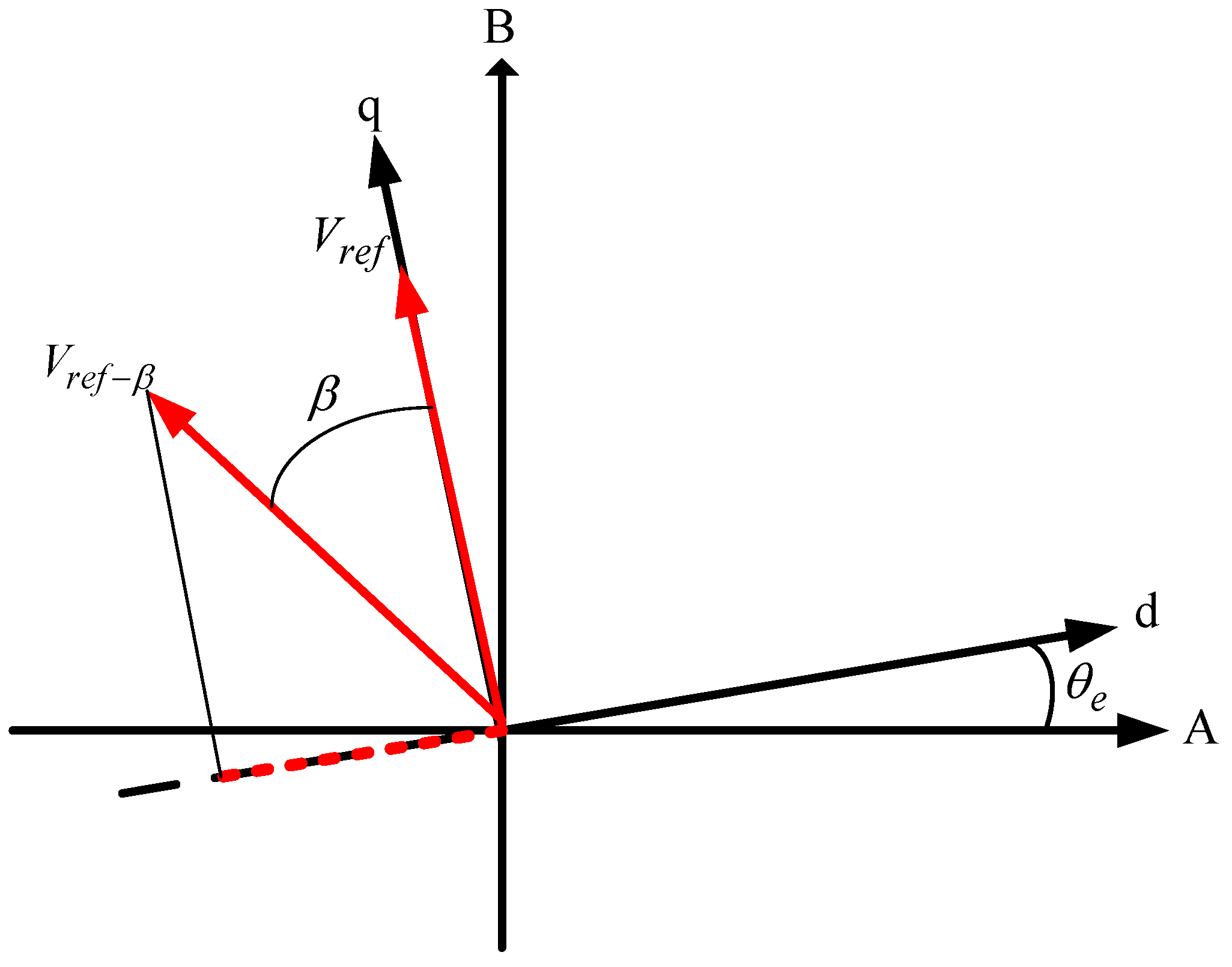
Four controllers are set in the drive system. The d-axis current command is set to 0 for the system controlled under the base speed, and is set to a negative amount for the field weaken operation, and the q-axis current command is from the output of the speed controller. To the object of field weaken control, the space voltage, , as shown in Figure 4, is placed at with a leading angle , instead of the normal position. In Figure 3, all the blocks are realized by FPGA except the stepper motor. Normally, an inner loop should have a faster sampling time than the outer loop, we thus set the sampling frequency to 20 kHz for the electrical loop (current control), and to 2 kHz for the mechanic loop (position/velocity control).
2.3. The Realization of the Drive System by FPGA
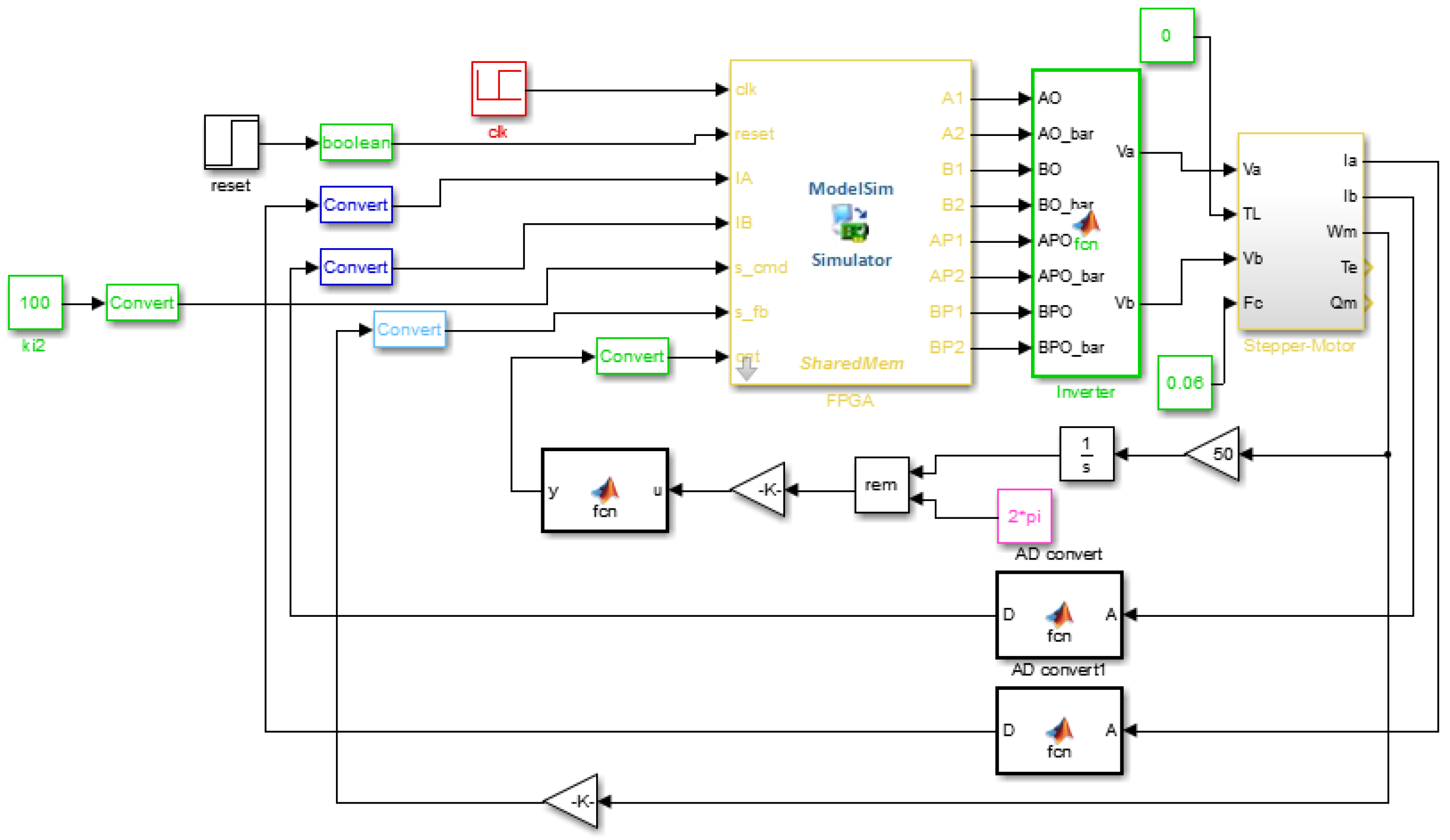
To realize the overall drive systems with FPGA, we first design the systems in Matlab/Simulink, and then simulate them using Modelsim to verify the correctness. Finally, the resulting block systems are converted into Verilog codes. The hardware systems are shown in Figure 5 where the block named as FPGA code located at the center in yellow is the hardware model of the proposed vector control drive system. The performances of the system by applying the hardware code to current/velocity/position controls will be shown in next section.
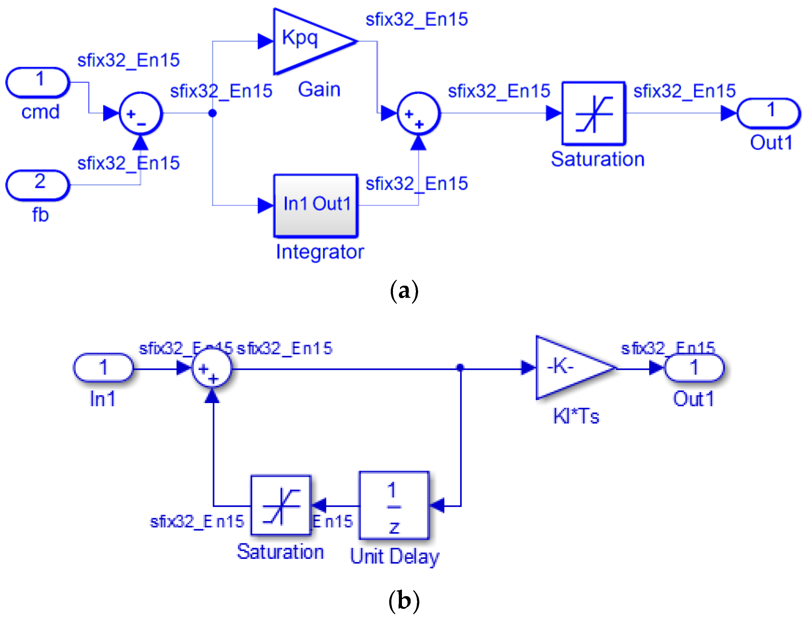
Some of the mathematic functions are illustrated to show the design. The PI controllers are realized in parallel as the block diagram shown in Figure 6a with the discrete-time transfer function (7).
where , , and are the proportional gain, integral gain, and sampling time, respectively.
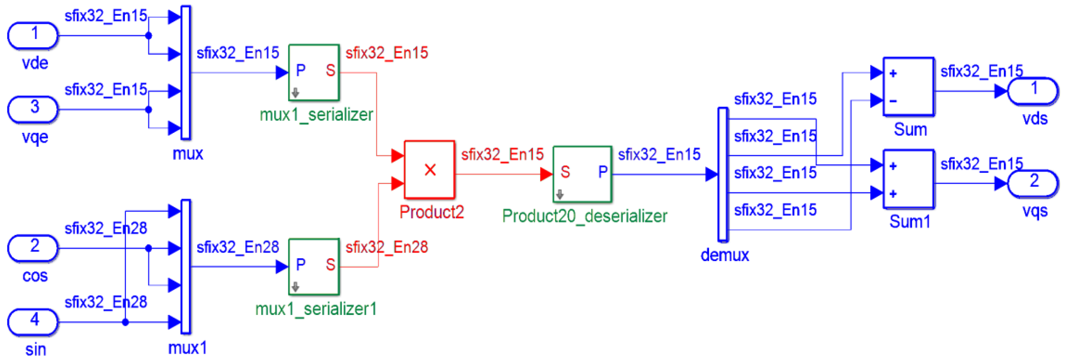
For all the designed system, the data bus is set as 32 bits with fixed-point operation, such as those marked on the signal flow path with sfix32_En15. In Figure 6a, cmd and fb represent the command input and output feedback, respectively, and 15 bits are set for the fractional part. In Figure 6b, the saturation is added as the anti-windup operation for the integral action. The PI controller is operated at 200 kHz clock. Regarding Figure 7, the block of 2e to 2s, as shown in Figure 3, executes the coordinate transformation (6). The input ports, and , are the voltages from the outputs of vector PI current controllers. The input ports of cos and sin come from the and tables, which are built by the embedded memory of FPGA, and both of them have 28-bit fractional parts. The mux is executed in 1 MHz clock, and 20 MHz for “Product2” block. Finally, the outputs of and have 15-bit fractional parts to be sent to space vector pulse width modulation (SVPWM) module to generate the desired trigger signals for power MOSFETs. To consider the most popular used range for the system, the date format of parameters and variables for current, speed, and position control are shown in Table 1.
3. The Functional Simulation and Discussions
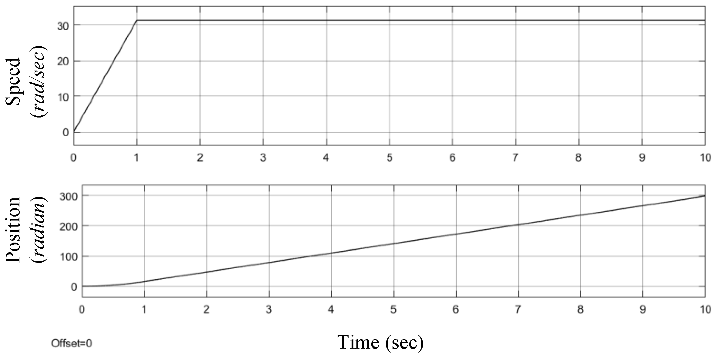
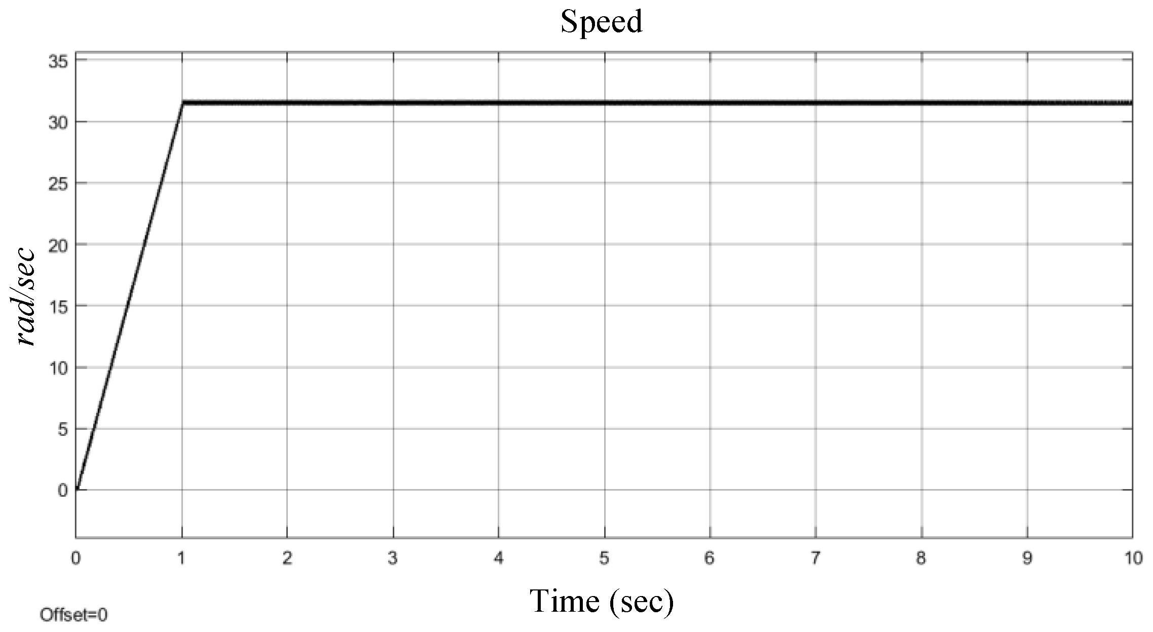
The functional simulation for the proposed FPGA-based drive system is demonstrated using Matlab/Simulink. The commands are generated by pulse generator, which outputs the pulse string command to the position controller with the maximum pulse rates of 31.4 rad/s, 314 rad/s, and 0.314 rad/s for the medium, high, and low speed commands, respectively. The above pulse rates result in maximum speed commands of 300 rpm, 3000 rpm, and 3 rpm, respectively. In the meanwhile, the accelerations are also taken into consideration for different pulse rates. Figure 8 demonstrates the generated speed and position commands for the system operated at 31.4 rad/s with acceleration of 31.4 rad/s2. The parameters of the controller for the simulated system are set as those shown in Table 2. Furthermore, for the speed command of 314 rad/s, the field weaken control is activated once the speed increases passed 100 rad/s, and a negative d-axis current command is added to let the system enter that region.
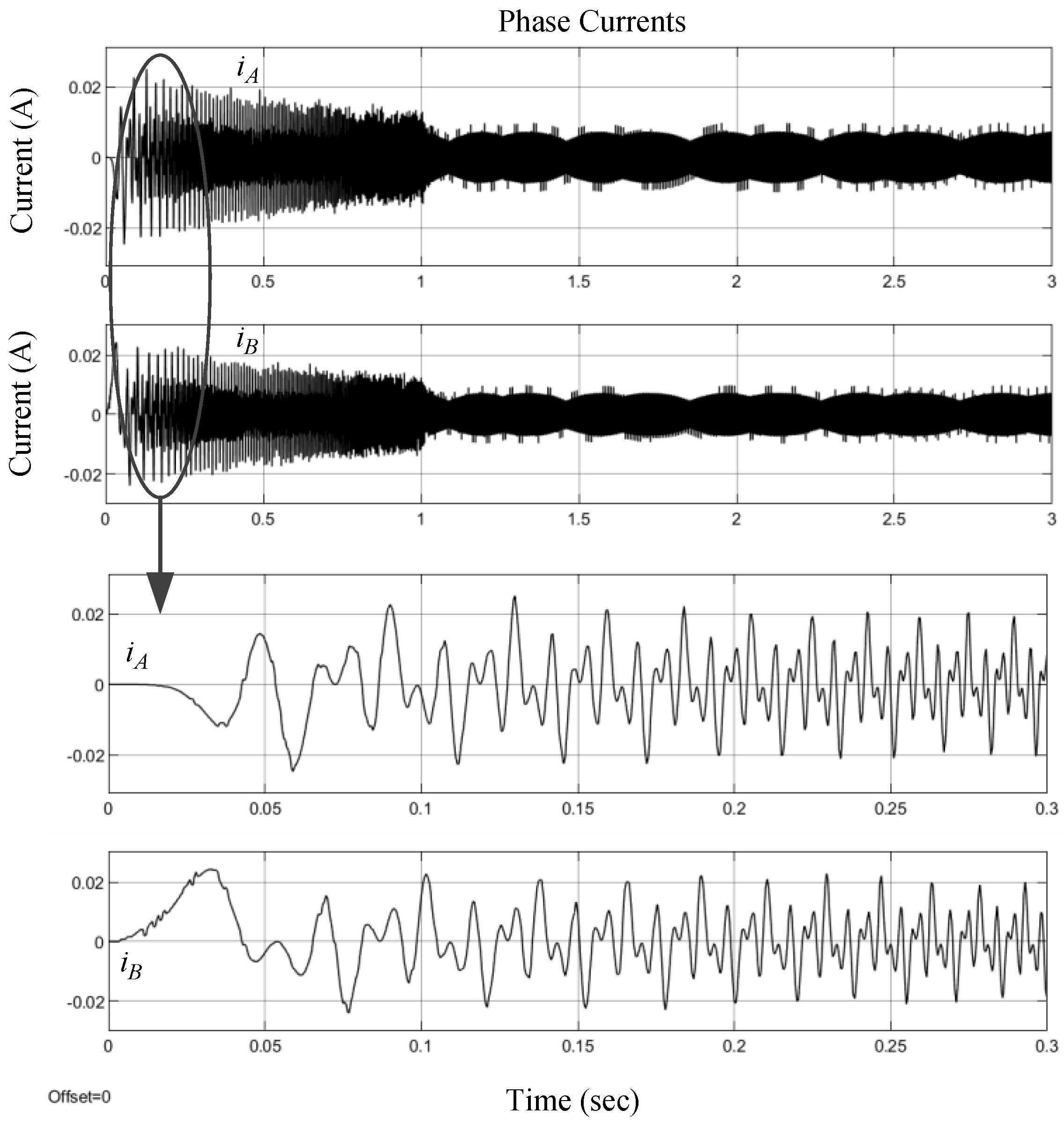
The simulated results for the command of pulse rate of 31.4 rad/s are shown in Figure 9 and Figure 10. The speed response of Figure 9 shows that the motor speed follows the pulse command and stays on it thereafter, and the current response of Figure 8 shows that the two stator currents are in quadrature.
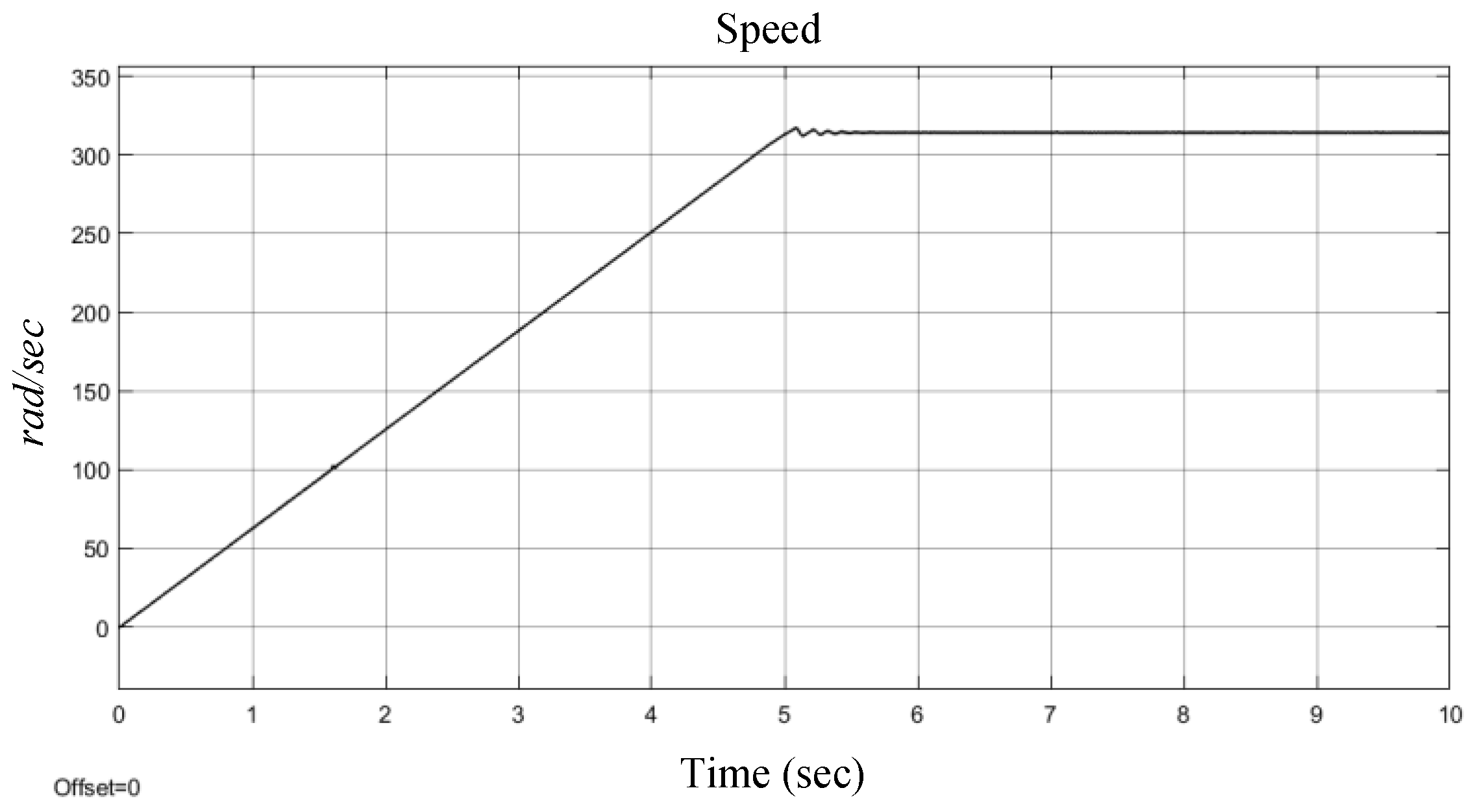
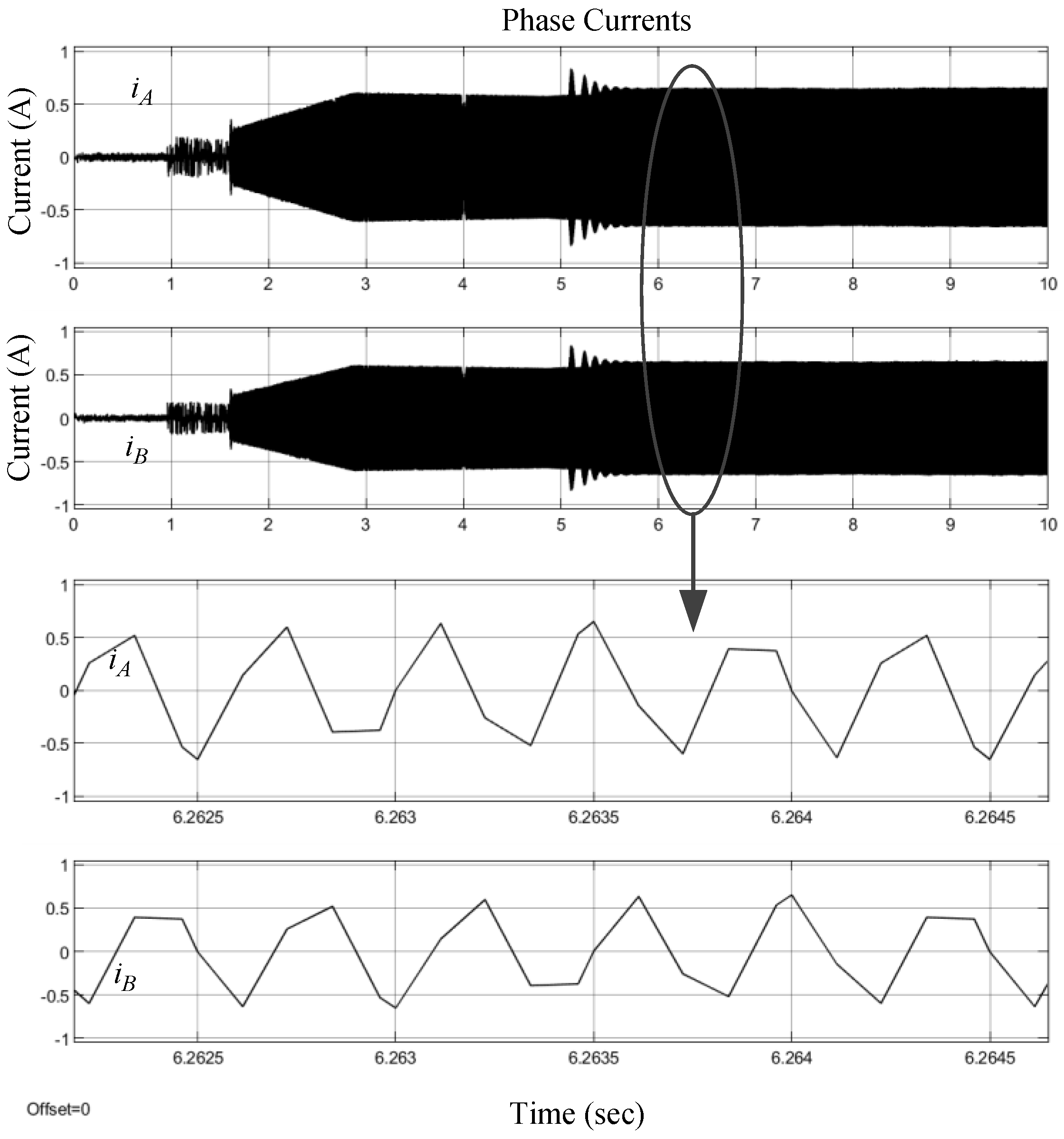
The simulated results for the speed command of 314 rad/s are shown in Figure 11 and Figure 12. Under this condition, the field weaken control is used. First, the region of field weaken begins when the speed is beyond 100 rad/s. Thus, during the acceleration, the current vector control enters the field weaken operation from the normal condition, which slightly affects the responses during the acceleration period. The system finally reaches the desired speed. Because the system enters the field weaken region, it requires a greater current than the one under the normal condition.
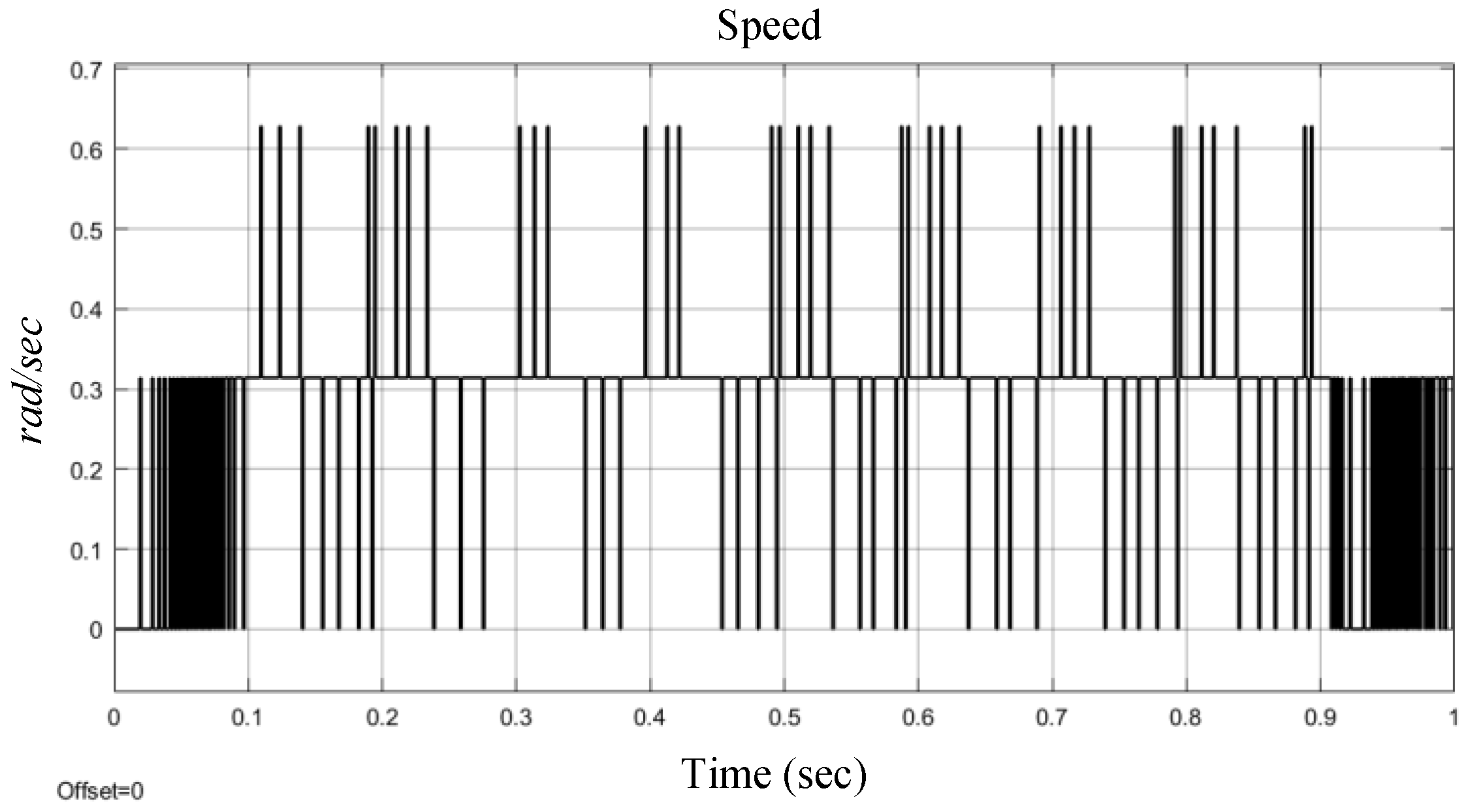
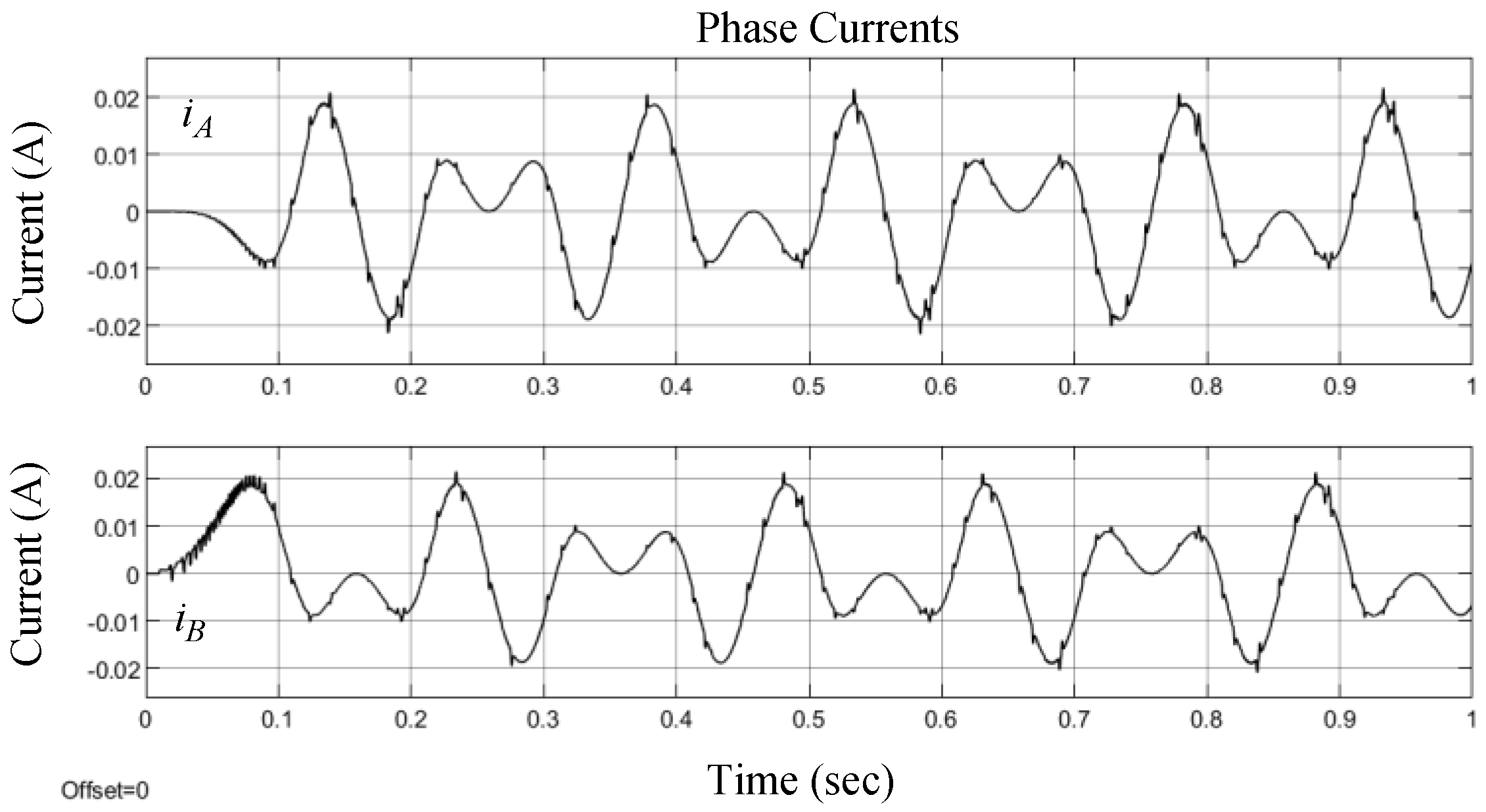
The simulated results for the speed command of 0.314 rad/s are shown in Figure 13 and Figure 14. As a result of the rather low speed operation, the speed response has a little resonance. As the speed feedback is from the difference of the encoder counter per sampling period, a low speed causes low precision on speed. This is also revealed in the current responses for the phases A and B. Of course, the low precision for speed feedback can be solved by calculating the period instead of the frequency of the encoder pulse. The procedure will be implemented for experiment.
4. The Experimental Results and Discussion
The commands are made by a pulse generator, which outputs the pulse string to the position controller, and the pulse rate is equal to the desired speed. The position controller accepts the pulse string and the feedback from the encoder counter to close the position control loop. The speed controller gets the encoder pulse, calculates the pulse rate, and converts it to the shaft speed as the feedback signal to close the speed control loop. Finally, the stator currents of the stepper motor are acquired from Hall current sensors, and fed back to FPGA through ADC to close the current control loop. As in the functional simulation, three speed commands, namely, 300 rpm, 3000 rpm, and 3 rpm, with different accelerations are practically used to test the performance of the developed hardware system. Furthermore, to demonstrate the performance of the pulse generator and position/speed controller, a 12-bit up/down counter is used to accumulate the pulses generated from the encoder. Its output is connected to a 12-bit DAC to convert the digital value of the counter to analog voltage, and is shown on the oscilloscope. The output voltage range of DAC is 0–5 V. According to the waveform of DAC, it is easy to verify the motor speed and check the smoothness of the rotation of the motor shaft. Furthermore, the motor is directly axis-coupled to a disk as the load, as shown in Figure 1.
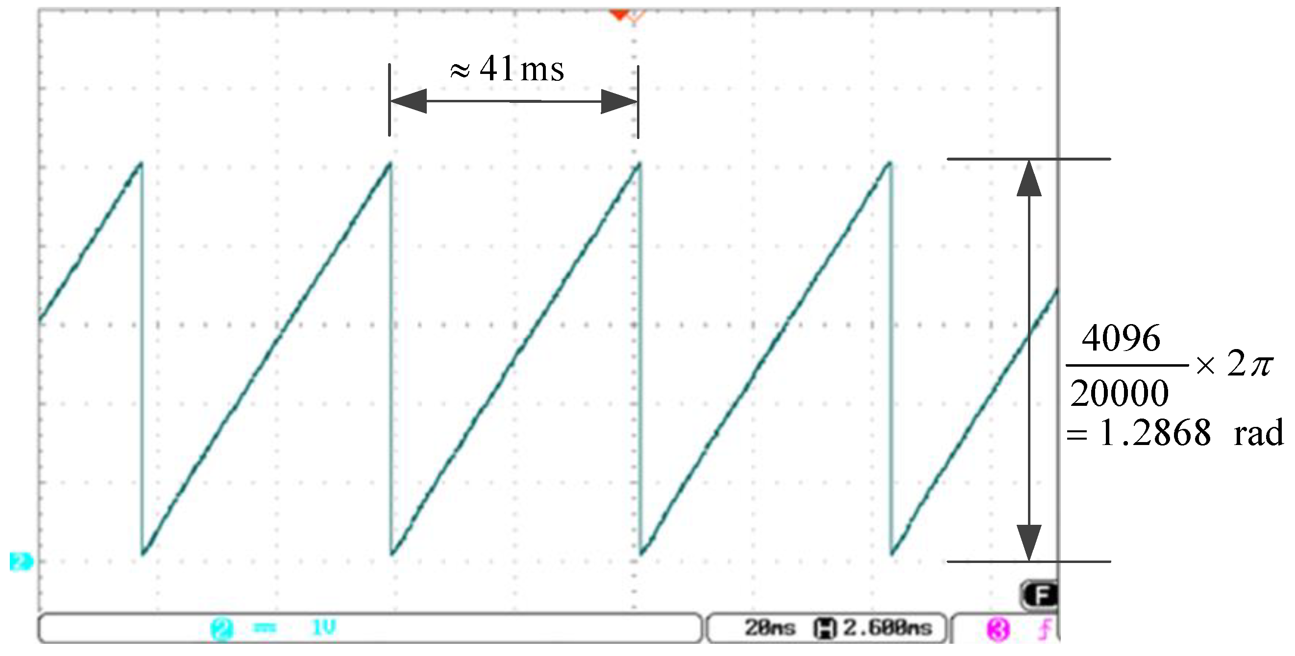
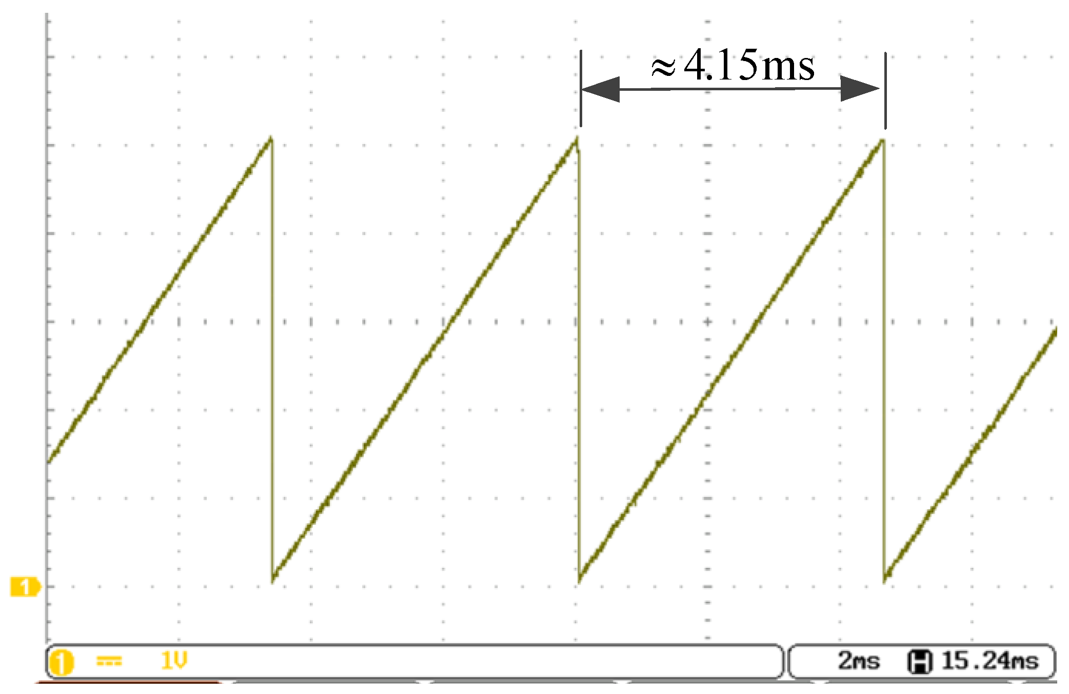
First, the output of DAC for 300 rpm speed command is shown in Figure 15, where the period is about 41 ms. Each of one triangle cycles is equal to 1.2868 radians, shown in (8).
The decimal range of the DAC counter is 0–4095, it has total 4096 counters, and the resolution of encoder is 20,000 p/rev. The motor speed can be obtaiuned by (9):
The waveform demonstrates that the speed is quite smooth under the proposed vector control system.
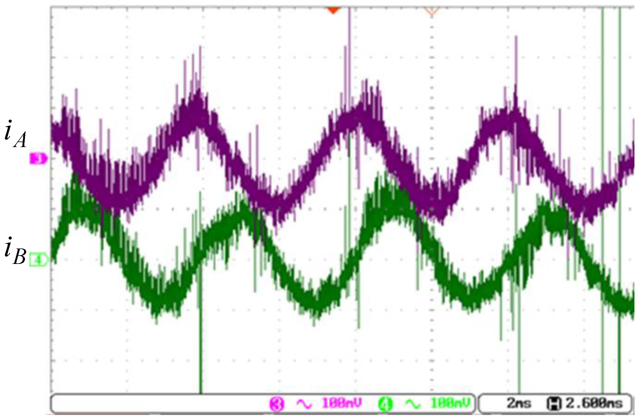
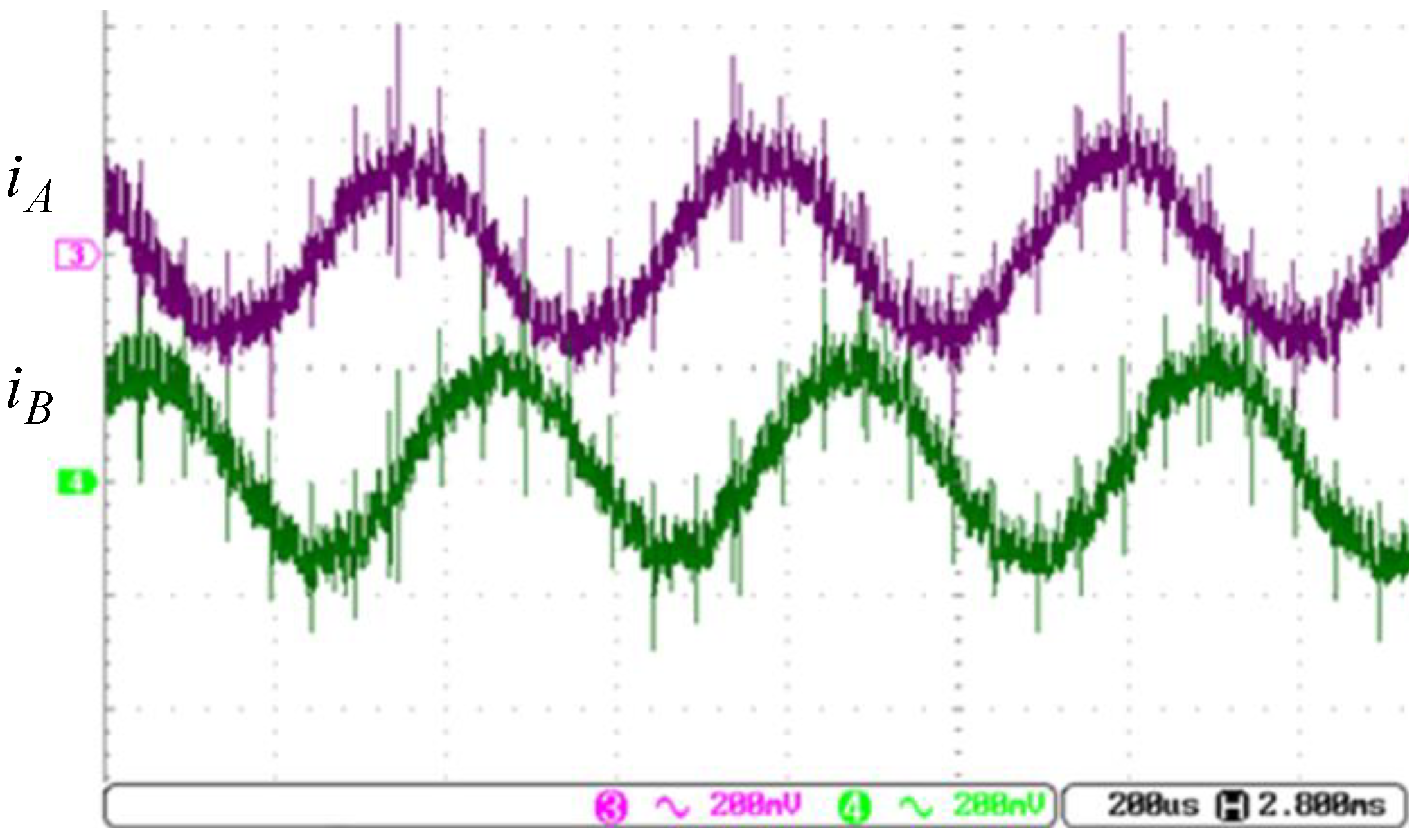
The current responses are shown in Figure 16, where the period is about 4 ms, and phase currents A and B are in quadrature. The peak-to-peak value of the current is about 1 A.
As the pole pair for the proposed hybrid stepper motor is 50, that is, P = 50. According to (10), the result is the same as the speed obtained from (9).
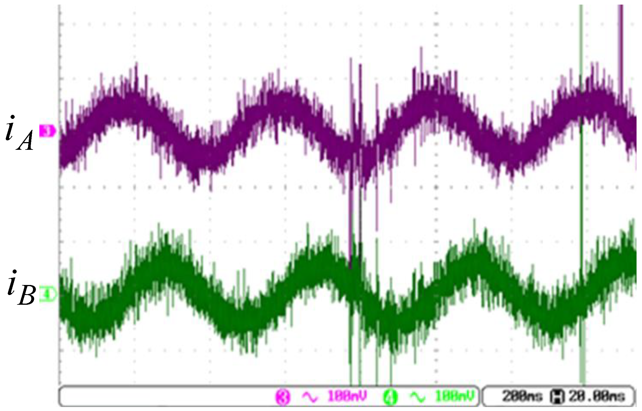
Next, we will demonstrate the performance with the speed command of 3000 rpm using the vector control, where the current control loop is in the field weaken region as the motor runs beyond the rated speed. The current responses of Figure 17 are the control results, where the peak-to-peak current is about 2 A. As the speed of 3000 rpm is beyond the rated speed, the direct component is a negative value by placing the voltage ahead of the q-axis.
The position responses for the speed command of 3000 rpm are shown in Figure 18. The motor speed from the curve shown in Figure 16 is approximately
The speed can also be verified by Figure 17, which has a period about 400 , which corresponds to 3000 rpm.
Compared with the results of Figure 15 and Figure 18, their sloping sides are very smooth, that is, the motor is run under a very stable condition.
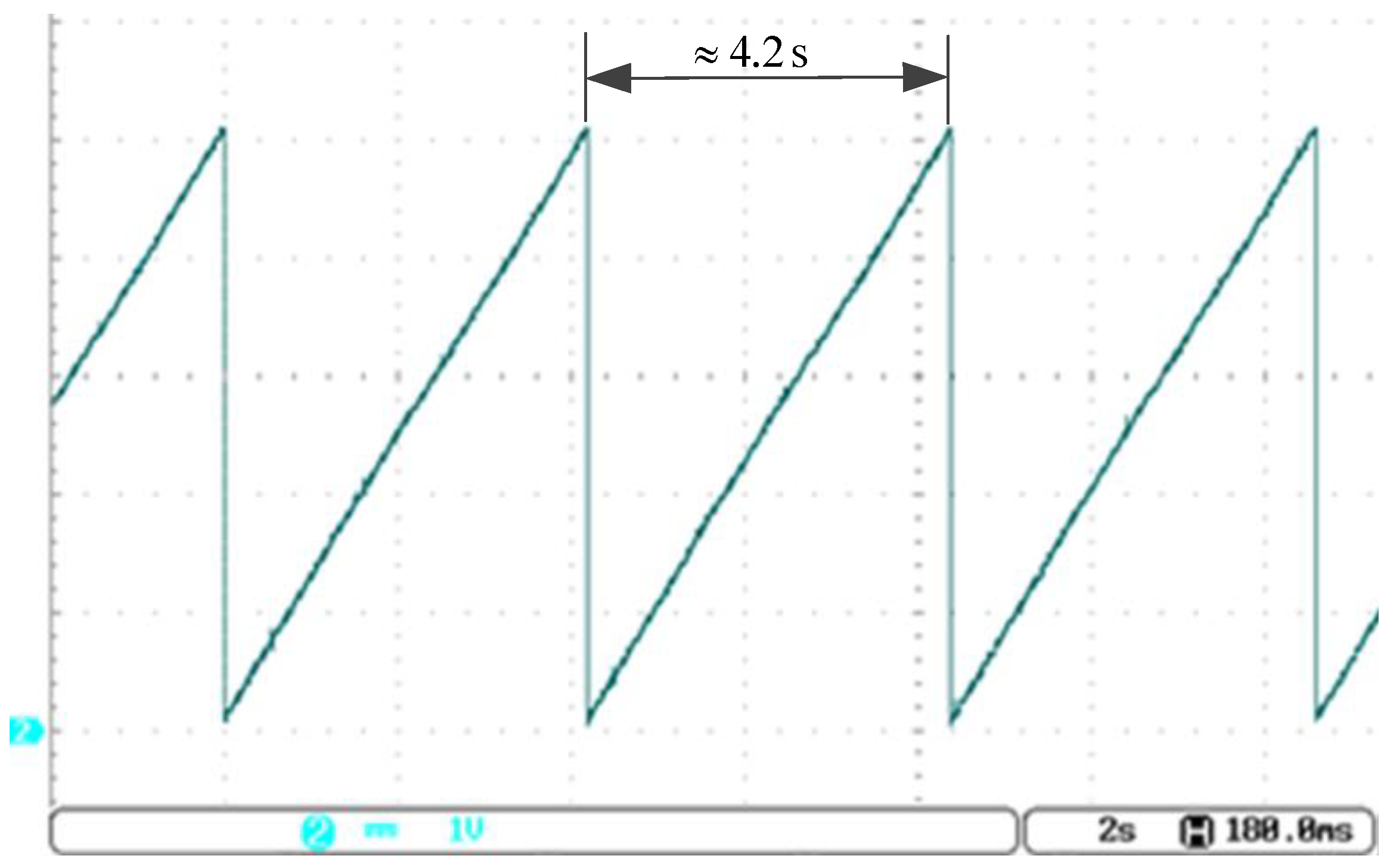
Finally, the low speed condition is performed with the speed command of 3 rpm, the position and current responses are shown in Figure 19 and Figure 20, respectively. With the position response of Figure 19, the speed is calculated as follows:
However, in the low speed range, the speed is calculated by measuring the period of the encoder pulse instead of the frequency. Furthermore, as the command is from the pulse string generator to the position controller, once the position error is very close to zero, the speed control loop will be skipped, and the current command will come directly from the position controller. With those strategies, we obtained a smooth speed response as in Figure 19, and current response as in Figure 20, where the phase currents are in quadrature.
In viewing those experimental results, one has demonstrated the performance for high, medium, and low speed commands, and the performances for different position/speed requirements are fitted to those desired through the closed-loop position and speed control.
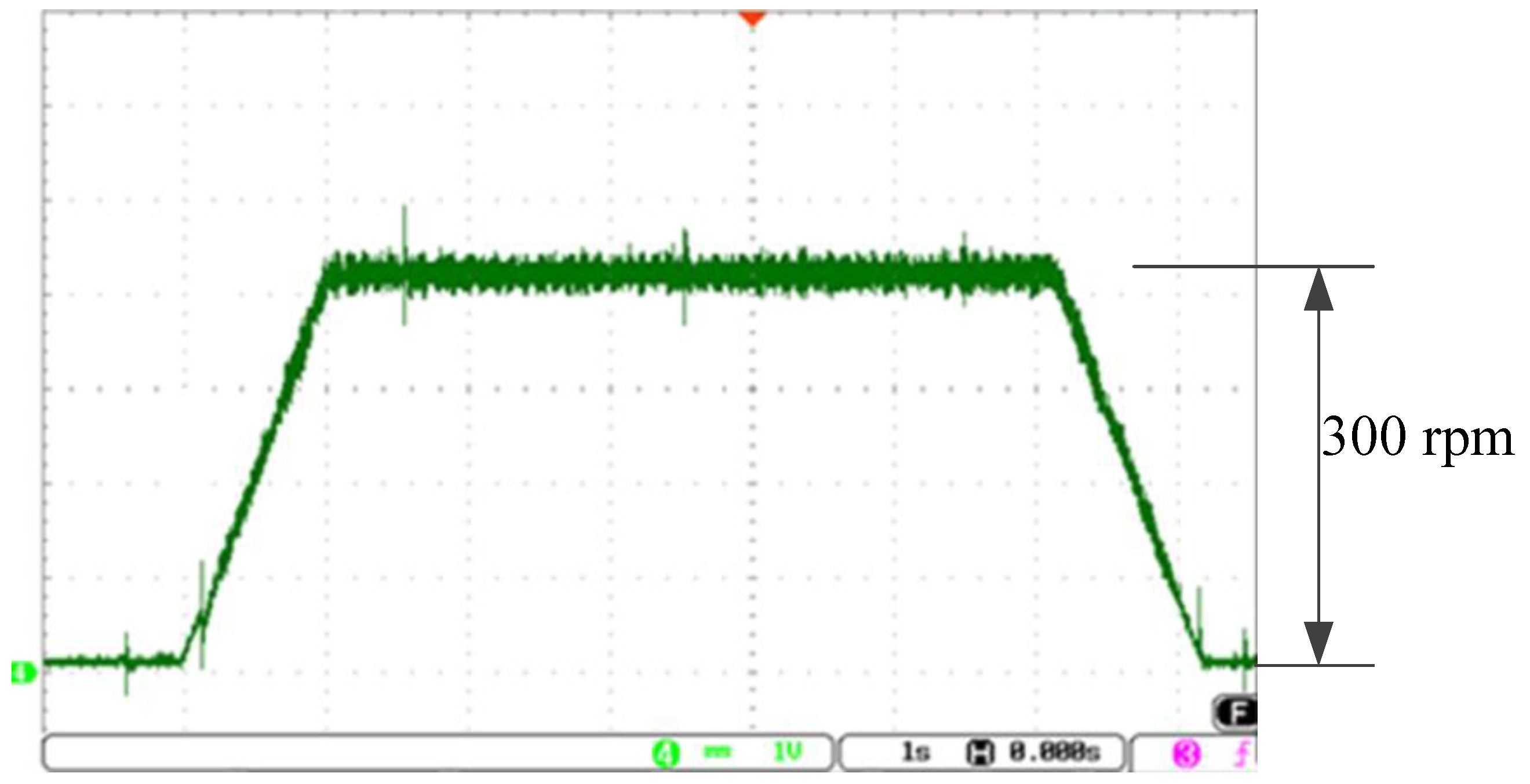
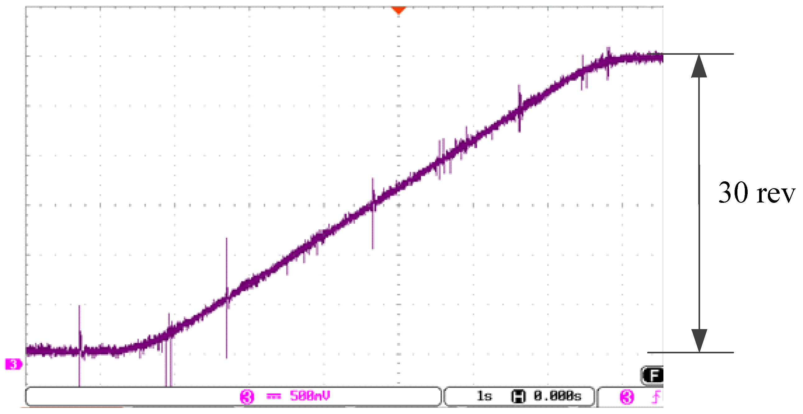
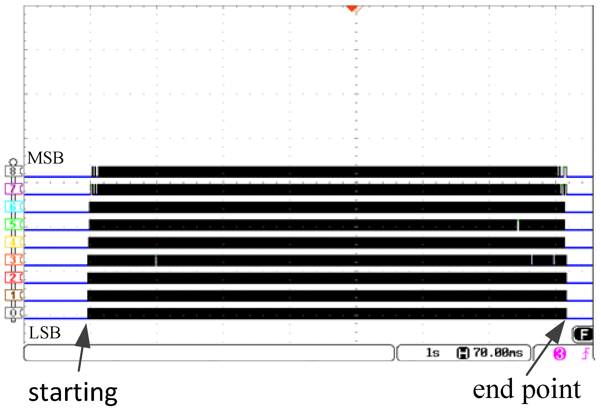
The position experimental results are shown in Figure 21, Figure 22 and Figure 23. The position command is to rotate the motor with the trapezoidal velocity profile as shown in Figure 21, where the acceleration and deceleration are and , respectively, and the maximum velocity is 300 rpm. The total rotation is 30 revolutions, which is equal to 600,000 counts from the encoder. The DAC is used to convert the digital position and velocity signals to analog voltage with the appropriate ratio, as shown in Figure 21 and Figure 22. To verify the end point value of the position counter, a 9-bit logical analyzer is used. The stepper motor of the experiment has pole pair 50 and 20,000 p/rev encoder, in which one electrical cycle is equal to 400 encoder pulses. Thus, we create a 400-step counter, which needs 9 bits in order to receive the pulses sent from the encoder, will be cleared (the value is 00000000) initially. According to Figure 23, the binary value of the 9-bit counter is 000000000 at the position marked “starting”. With the control of position controller and the pulse string generator, the value at the end point is also 000000000, that is, in this experiment, the final position stops exactly at the command.
5. Conclusions
In this paper, we have demonstrated the design of stepper motor position/speed/current controllers with different speed commands to verify the performances when the control system is completely constructed by FPGA and ADC as an embedded system. With the current vector control, and considering the field weaken region operation, we have successfully made the stepper motor operate in low, medium, and high speeds with load condition. As a result of the design of the closed-loop control for position and speed, the stepper motor drive has been presented to be able to be used in a wide range of speed applications, such as those shown in Figure 21, Figure 22 and Figure 23. This system can be combined into a complete motion control system, which includes the motion controller and motor drive.
Author Contributions
Conceptualization, C.-K.L. and J.-S.C.; Methodology, C.-K.L. and J.-S.C.; Software, J.-S.C. and C.-C.T.; Validation, J.-S.C. and C.-C.T.; Formal Analysis, C.-K.L., J.-S.C., and C.-C.T.; Investigation, C.-K.L., J.-S.C., and C.-C.T.; Resources, C.-K.L.; Data Curation, J.-S.C. and C.-C.T.; Writing—Original Draft Preparation, C.-K.L., J.-S.C., and C.-C.T.; Writing—Review & Editing, C.-K.L. and J.-S.C.; Visualization, C.-K.L., J.-S.C., and C.-C.T.; Supervision, C.-K.L.; Project Administration, C.-K.L.; Funding Acquisition, C.-K.L.
Funding
This research was funded by [Ministry of Science and Technology of Taiwan] grant number [MOST 106-2622-E-167-008-CC3].
Conflicts of Interest
The authors declare no conflict of interest.
References
- Lu, W.; Wang, Q.; Ji, K.; Dong, H.; Lin, J.; Qian, J. Research on Closed-loop Drive System of Two-phase Hybrid Step Motor Based on SVPWM. In Proceedings of the IEEE Vehicle Power and Propulsion Conference (VPPC), Hangzhou, China, 17–20 October 2016. [Google Scholar]
- Crnoˇsija, P.; Kuzmanovic, B.; Ajdukovic, S. Microcomputer Implementation of Optimal Algorithms for Closed-Loop Control of Hybrid Stepper Motor Drives. IEEE Trans. Ind. Electron. 2000, 47, 1319–1325. [Google Scholar]
- Le, K.M.; van Hoang, H.; Jeon, J.W. An Advanced Closed-Loop Control to Improve the Performance of Hybrid Stepper Motors. IEEE Trans. Power Electron. 2017, 32, 7244–7255. [Google Scholar] [CrossRef]
- Chaurasiya Rohit, B.; Mukesh, D.; Patil, D.S.; Kadam, A. FPGA Implementation of SVPWM Control Technique for Three Phase Induction Motor Drive Using Fixed Point Realization. In Proceedings of the International Conference on Circuits, Systems, Communication and Information Technology Applications (CSCITA), Mumbai, India, 4–5 April 2014; pp. 93–98. [Google Scholar]
- Kung, Y.-S.; Tsai, M.-H. FPGA-Based Speed Control IC for PMSM Drive with Adaptive Fuzzy Control. IEEE Trans. Power Electron. 2007, 22, 2476–2486. [Google Scholar] [CrossRef]
- Quynh, N.V.; Kung, Y.-S. FPGA-Realization of Fuzzy Speed Controller for PMSM Drives without Position Sensor. ICCAIS 2013, 278–282. [Google Scholar] [CrossRef]
- Kenneth, W.H.; Tsui, N.C. Cheung, Novel Modeling and Damping Technique for Hybrid Stepper Motor. IEEE Trans. Ind. Electron. 2009, 56, 202–211. [Google Scholar]
- Kocur, M.; Kozak, S.; Dvorscak, B. Design and Implementation of FPGA—Digital Based PID Controller. In Proceedings of the 15th International Carpathian Control Conference (ICCC), Ostrava, Czech Republic, 28–30 May 2014; pp. 233–236. [Google Scholar]
- Siwakoti, Y.P.; Town, G.E. Design of FPGA-Controlled Power Electronics and Drives Using MATLAB Simulink. In Proceedings of the IEEE/ECCE Asia, Melbourne, Australia, 3–6 June 2013; pp. 571–577. [Google Scholar]
- Lai, C.-K.; Tsao, Y.-T.; Tsai, C.-C. Modeling, Analysis, and Realization of Permanent Magnet Synchronous Motor Current Vector Control by MATLAB/Simulink and FPGA. Machines 2017, 5, 26. [Google Scholar] [CrossRef]
- Stumpf, A.; Elton, D.; Devlin, J.; Lovatt, H. Benefits of an FPGA based SRM controller. In Proceedings of the IEEE 9th Conference on Industrial Electronics and Applications (ICIEA), Hangzhou, China, 9–11 June 2014; pp. 12–17. [Google Scholar]
- Horvat, R.; Jezernik, K.; Čurkovič, M. An Event-Driven Approach to the Current Control of a BLDC Motor Using FPGA. IEEE Trans. Ind. Electron. 2014, 61, 3719–3726. [Google Scholar] [CrossRef]
- Lai, C.-K.; Chien, W.-N.; Tsai, S.-L.; Tsao, Y.-T. The Modelling, Simulation and Hardware Implementation for FPGA-based Stepping Motor Motion Drive. Int. J. Comput. Consum. Control 2016, 5, 33–47. [Google Scholar]
Figure 1.
The setup for experiment. (a) The field programmable gate array (FPGA) board and power module; (b) the experimental platform.
Figure 1.
The setup for experiment. (a) The field programmable gate array (FPGA) board and power module; (b) the experimental platform.

Figure 2.
The block diagram of the stepper motor drive system. DAC—digital to analog converter; ADC—analog to digital converter.
Figure 2.
The block diagram of the stepper motor drive system. DAC—digital to analog converter; ADC—analog to digital converter.

Figure 3.
The block diagram for the drive system.

Figure 4.
The vector control for phase currents.

Figure 5.
The resulting hardware digital control system.

Figure 6.
The block diagram for the PI controller. (a) The PI structure; (b) the integral control part.
Figure 6.
The block diagram for the PI controller. (a) The PI structure; (b) the integral control part.

Figure 7.
The data format for the reference frame transformation.

Figure 8.
The speed and position responses by pulse generator.

Figure 9.
The simulated speed response of speed command of 31.4 rad/s.

Figure 10.
The simulated stator current responses for the speed command of 31.4 rad/s.

Figure 11.
The simulated speed response of speed command of 314 rad/s.

Figure 12.
The simulated stator current responses for the speed command of 314 rad/s.

Figure 13.
The simulated speed response of the speed command of 0.314 rad/s.

Figure 14.
The simulated stator current responses for the speed command of 0.314 rad/s.

Figure 15.
The output of position counter by DAC for the speed command of 300 rpm.

Figure 16.
The phase currents A and B of the command of 300 rpm (185 mV/A).

Figure 17.
The phase currents A and B of the command of 3000 rpm (185 mV/A).

Figure 18.
The position responses for the speed command of 3000 rpm.

Figure 19.
The position responses for the speed command of 3 rpm.

Figure 20.
The current responses for the speed command of 3 rpm (185 mV/A).

Figure 21.
The trapezoidal velocity profile (70 rpm/div).

Figure 22.
The position response (5 rev/div).

Figure 23.
The logical analyzer output for position response.


Table 1.
The data format of the variables and parameters.
| Name | Unit | Sign | Integer Part | Fractional Part | Remark |
|---|---|---|---|---|---|
| 1 | 16 | 15 | Proportional gain | ||
| 1 | 16 | 15 | Integral gain | ||
| # pulse | 1 | 31 | 0 | Position | |
| rad/sec | 1 | 16 | 15 | Velocity | |
| A | 1 | 16 | 15 | d-axis current | |
| A | 1 | 16 | 15 | q-axis current | |
| V | 1 | 16 | 15 | d-axis voltage | |
| V | 1 | 16 | 15 | q-axis voltage | |
| 1 | 3 | 28 | |||
| 1 | 3 | 28 |
* Remark: The units for proportional and integral control gains can be found in Table 2.
Table 2.
The parameters of the proposed control system.
| Type | ||
|---|---|---|
| Position control loop | 0.1 (rad/s/p) | 0 |
| Speed control loop | 0.1 (A/rad/s) | 0.03 (rad/p·s) |
| d-axis control loop | 16 (V/A) | 0.01 (V/A·s) |
| q-axis control loop | 16 (V/A) | 0.01 (V/A·s) |
© 2018 by the authors. Licensee MDPI, Basel, Switzerland. This article is an open access article distributed under the terms and conditions of the Creative Commons Attribution (CC BY) license (http://creativecommons.org/licenses/by/4.0/).
Share and Cite
MDPI and ACS Style
Lai, C.-K.; Ciou, J.-S.; Tsai, C.-C. The Modelling, Simulation and FPGA-Based Implementation for Stepper Motor Wide Range Speed Closed-Loop Drive System Design. Machines 2018, 6, 56. https://doi.org/10.3390/machines6040056
AMA Style
Lai C-K, Ciou J-S, Tsai C-C. The Modelling, Simulation and FPGA-Based Implementation for Stepper Motor Wide Range Speed Closed-Loop Drive System Design. Machines. 2018; 6(4):56. https://doi.org/10.3390/machines6040056
Chicago/Turabian StyleLai, Chiu-Keng, Jhang-Shan Ciou, and Chia-Che Tsai. 2018. "The Modelling, Simulation and FPGA-Based Implementation for Stepper Motor Wide Range Speed Closed-Loop Drive System Design" Machines 6, no. 4: 56. https://doi.org/10.3390/machines6040056
Note that from the first issue of 2016, this journal uses article numbers instead of page numbers. See further details here.