Mathematical Model of New Type of Train Buffer Made of Polymer Absorber—Determination of Dynamic Impact Curve for Different Temperatures

Abstract
:1. Introduction
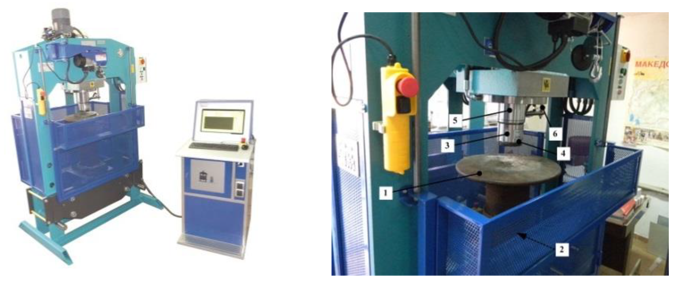
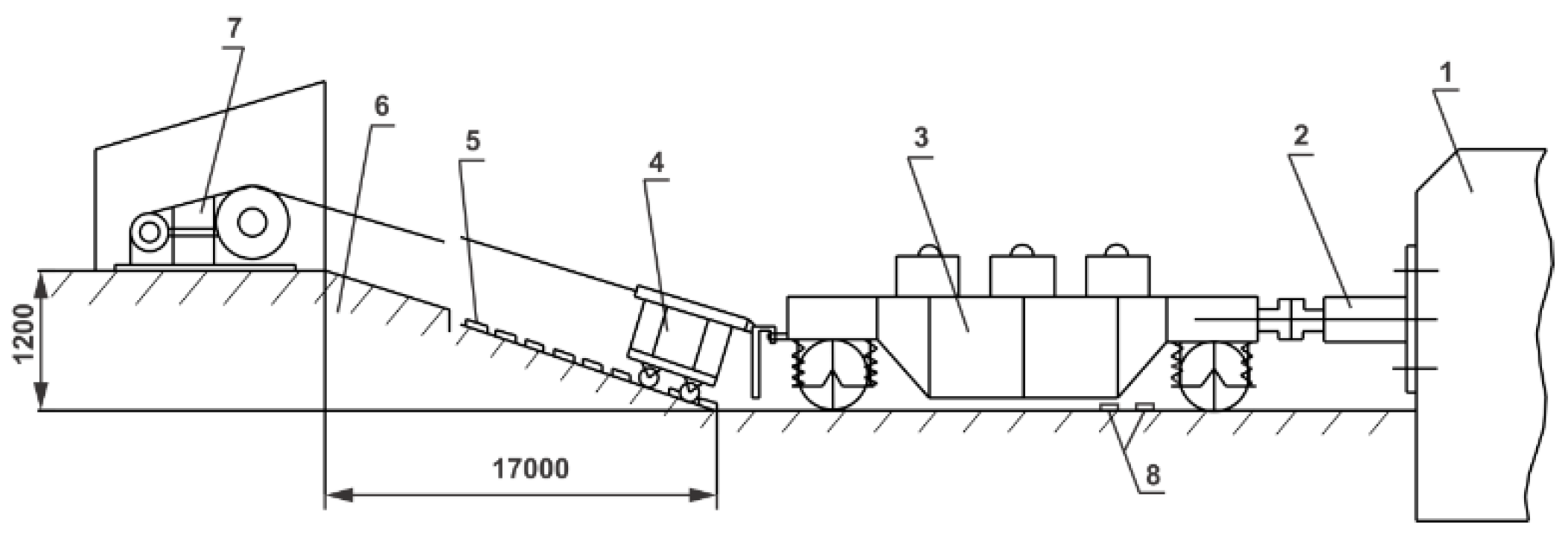
2. Experimental Determination of Absorber Curves
3. Mathematical Model
4. Result and Discussion
5. Conclusions
- The model can be used to analyze the action of the longitudinal forces that occur during transient conditions of the movement of the carriages.
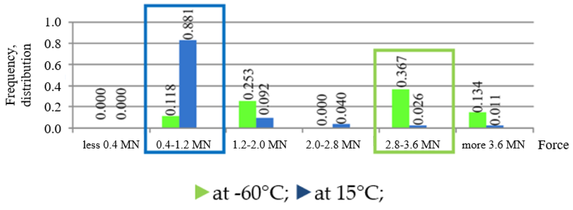
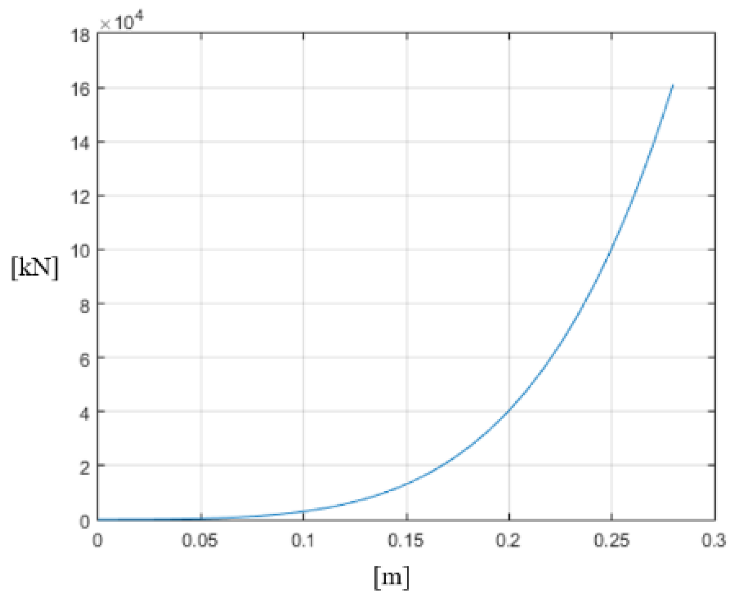
- The dynamic force obtained for a working temperature of +15 °C is five times greater than the dynamic force obtained for a working temperature of −60 °C. This indicates that the influence of the temperature change is of great importance.
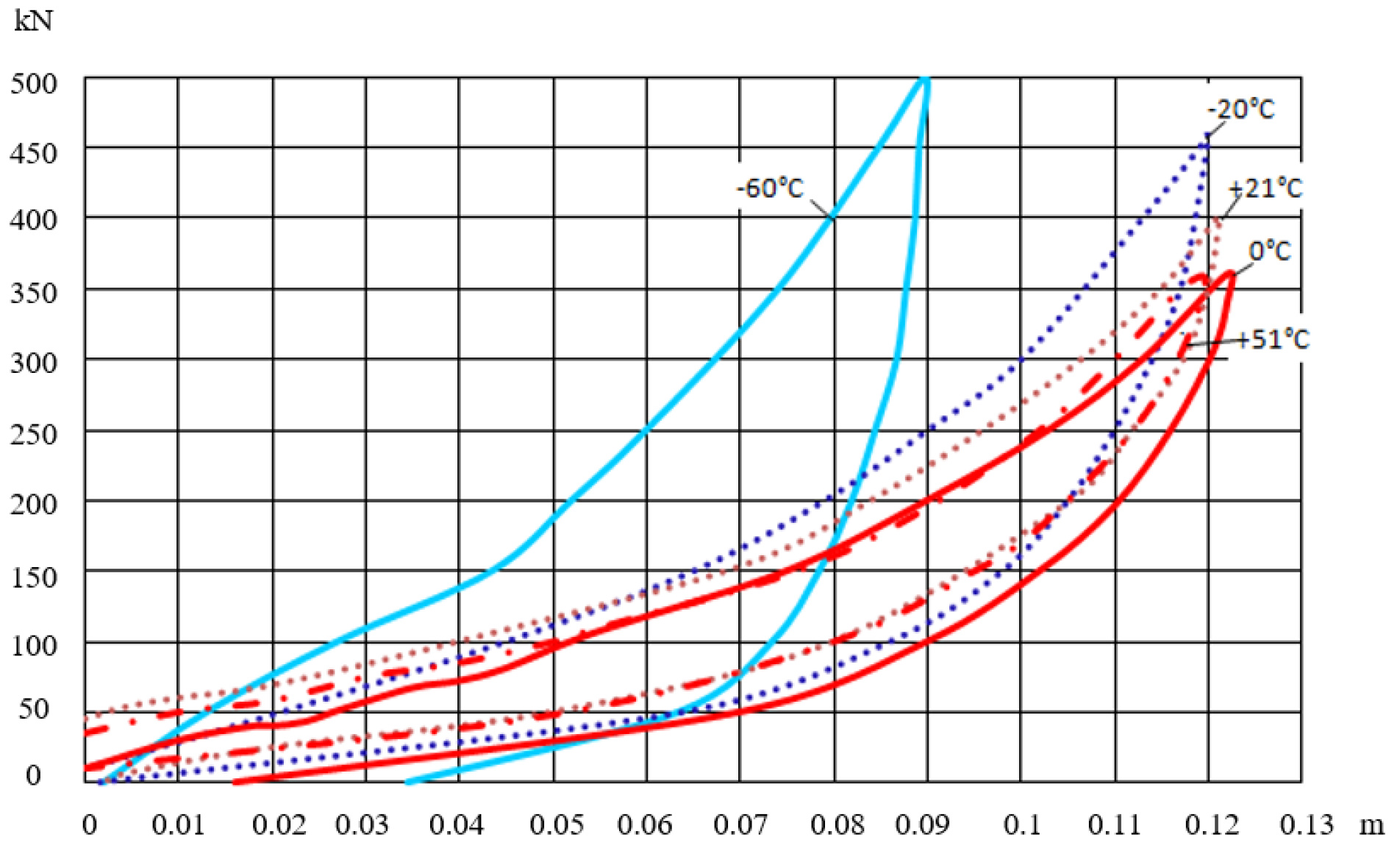
- For a working temperature of +15 °C and a working stroke of 180 mm, it was calculated that ; meanwhile, for a working temperature of −60 °C, . For a working temperature of +15 °C and a working stroke of 150 mm, it was calculated that ; for a working temperature of −60 °C, . This can be seen from the diagrams in Figure 9 and Figure 12 and this ratio is maintained for the whole working length of the polymer block.
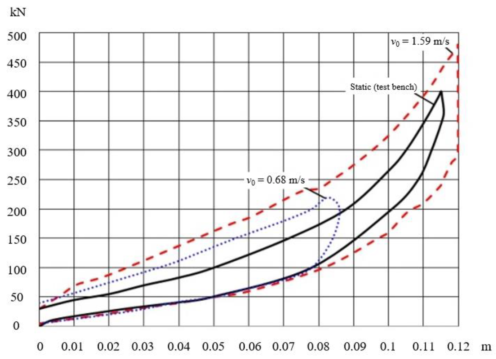
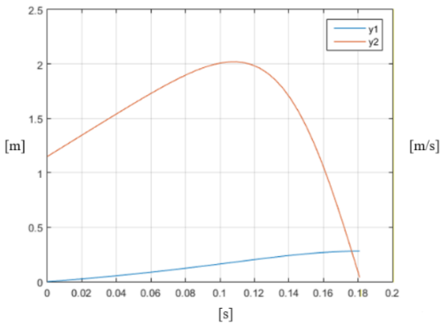
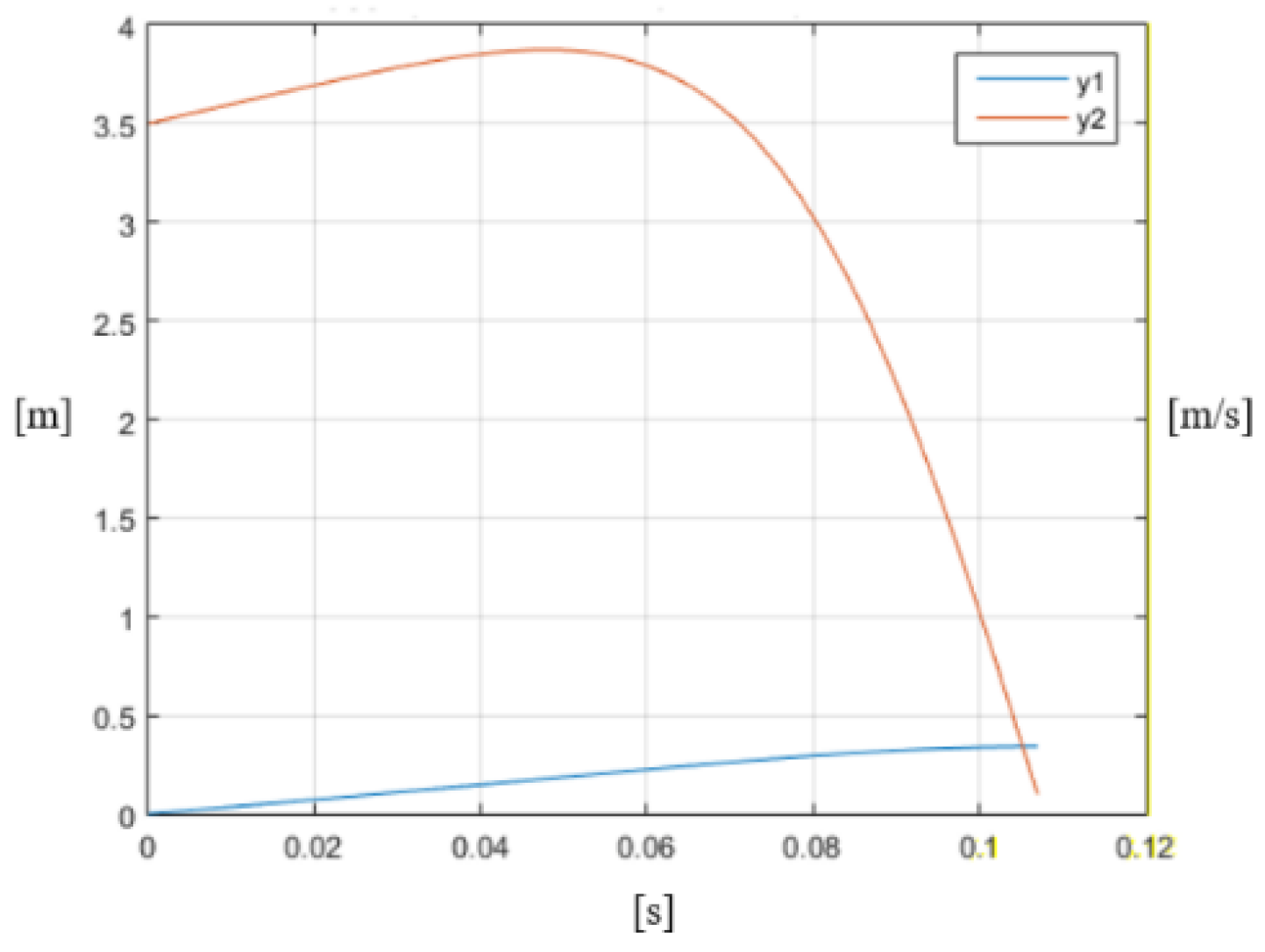
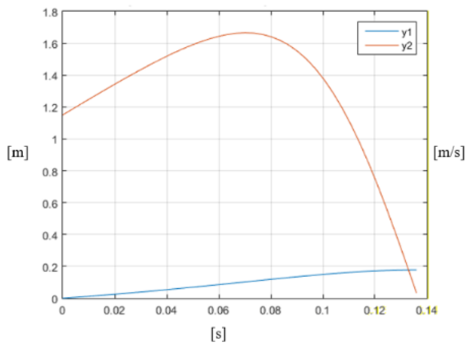
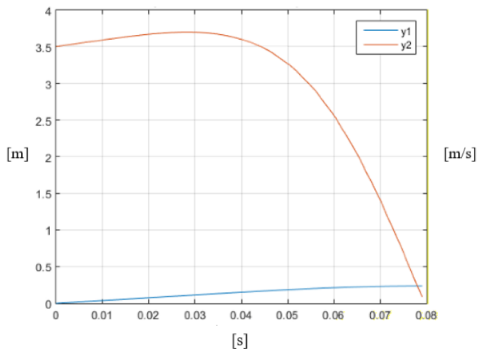
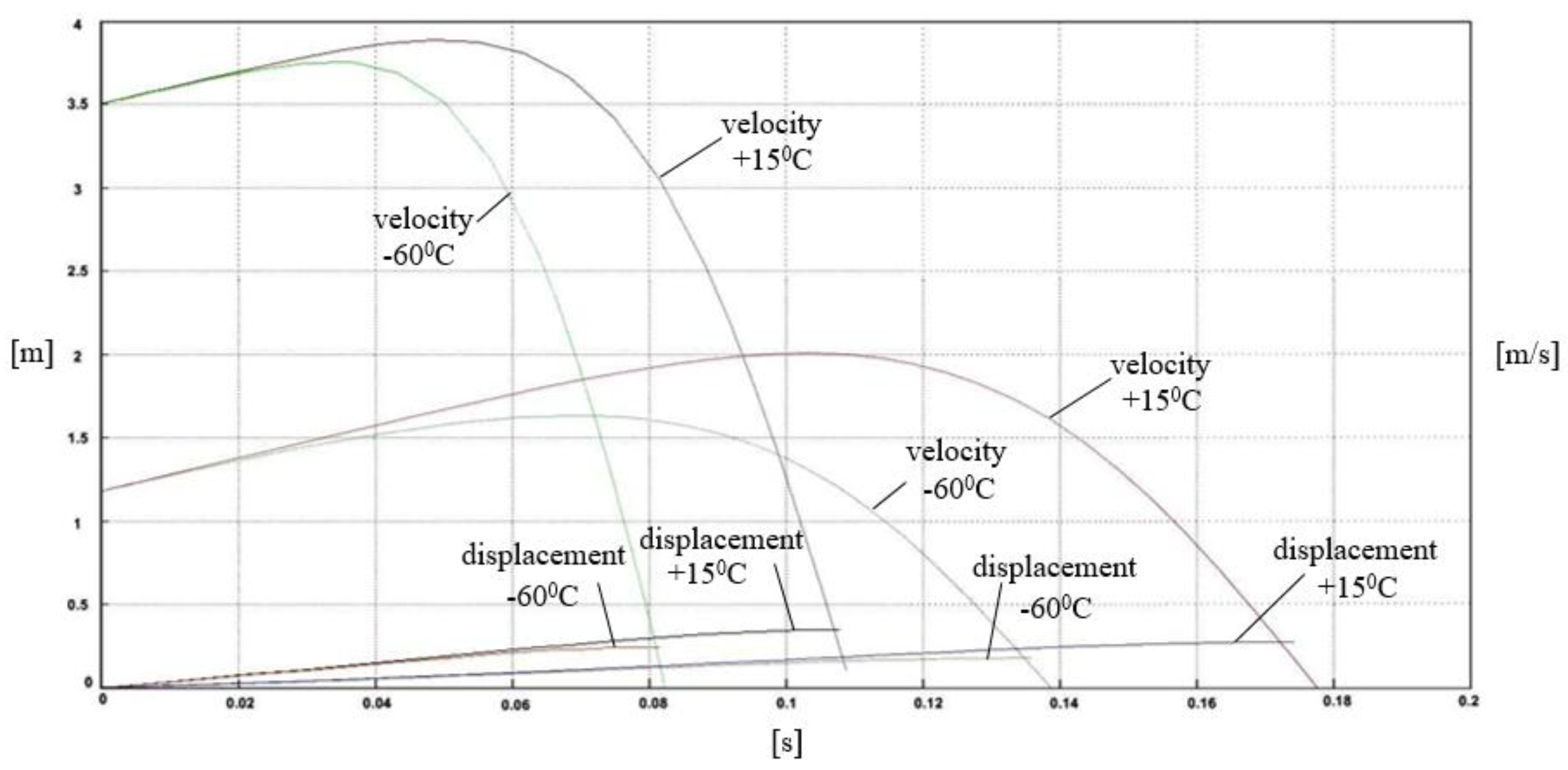
- In the process of operation, the initial impact velocity increases and then drops to zero. At higher speeds, the percentage of this increase is lower. For example, for an initial velocity v0 = 3.5 m/s, the increase is about 1%, and for v0 = 1.15 m/s it is about 6%.
- Expensive classical experiments can be avoided, and the error of the force obtained with the mathematical model does not exceed 5% related to the maximum force, and does not exceed 1% related to the maximum displacement.
Author Contributions
Funding
Conflicts of Interest
References
- Spiryagin, M.; Cole, C.; Sun, Y.; McClanachan, M.; Spiryagin, V.; McSweeney, T. Design and Simulation of Rail Vehicles; CRC Press: Boca Raton, FL, USA, 2014. [Google Scholar]
- Spiryagin, M.; Wolfs, P.; Cole, C.; Spiryagin, V.; Sun, Y.; McSweeney, T. Design and Simulation of Heavy Haul Locomotives and Trains; CRC Press: Boca Raton, FL, USA, 2017. [Google Scholar]
- Qing, W.; Colin, C.; Shihui, L.; Maksym, S. A review of dynamics modelling of friction draft gear. Veh. Syst. Dyn. 2014, 52, 733–758. [Google Scholar] [CrossRef]
- Colin, C.; Maksym, S.; Qing, W.; Yan, Q.S. Modelling, simulation and applications of longitudinal train dynamics. Veh. Syst. Dyn. 2017, 55, 1498–1571. [Google Scholar] [CrossRef]
- Qing, W.; Xiangjian, Y.; Colin, C.; Shihui, L. Modelling polymer draft gears. Veh. Syst. Dyn. 2016, 54, 1208–1225. [Google Scholar] [CrossRef]
- Alexander, O.; Alexey, O.; Chang-Wan Kim Hyun-Ik, Y. An improved dynamic model of friction draft gear with a transitional characteristic accounting for housing deformation. Veh. Syst. Dyn. 2018, 56, 1471–1491. [Google Scholar] [CrossRef]
- Qing, W.; Maksym, S.; Colin, C. Advanced dynamic modelling for friction draft gears. Veh. Syst. Dyn. 2015, 53, 475–492. [Google Scholar] [CrossRef]
- Alexander, O.; Alexey, O.; Svetlana, I.; Chang-Wan, K.; Hyun-Ik, Y. Freight cars shunting impacts analysis using an improved dynamic model of friction draft gear. Veh. Syst. Dyn. 2018, 56, 1492–1507. [Google Scholar] [CrossRef]
- Iwnicki, S. Handbook of Railway Vehicle Dynamics; CRC Press: Boca Raton, FL, USA, 2006; p. 359. [Google Scholar]
- Zirov, P.D.; Kravcov, S.A. Taking into account of temperature factor in the simulation of operation of friction-polymer absorber couplers. In Proceedings of the II International Scientific and Technical Conference: Computer Modeling in Rail Transport: Dynamics, Durability, Wear, Bryansk, Russia, 9–10 April 2014; pp. 20–22. [Google Scholar]
- Boldyrev, A.P.; Zirov, P.D. Development of a mathematical model and calculation of the characteristics of an auto-coupling absorbing apparatus with polymer elements at various ambient temperatures. Bull. Bryansk State Tech. Univ. 2010, 7, 55–58. [Google Scholar]
- EN 15551-2017, Railway Application. Railway Rolling Stock, Buffers; UIC 526-3 Dynamic Characterisctics; AENOR: Madrid, Spain, 2007.
- Durel. Available online: https://www.durel.de/Media/Downloads/EN/DUREL-ProductFlyer-Buffer-Springs-EN-2013-01-11.pdf (accessed on 8 August 2018).
- Vassilyev, A.S.; Boldyrev, A.P. The Experimental Studies of Modern Frictional Blow Shock-Absorbers of the Railroads Rolling Stock. Bull. Bryansk State Tech. Univ. 2013, 15, 507–510. [Google Scholar]
- Boldyrev, A.P.; Vassilyev, A.S. Characteristics computation for modern shock isolators of rolling-stock using appropriate simulators. Bull. Bryansk State Tech. Univ. 2015, 12, 19–26. [Google Scholar] [CrossRef]
- Zirov, P.D. Modeling of operational factors affecting the efficiency of modern absorbing devices. In Proceedings of the III International Scientific and Technical Conference: Achievements of Young Scientists in the Development of Innovative Processes in the Economy, Science, Education, Bryansk, Russia, 11–12 October 2011; pp. 24–25. [Google Scholar]
- Keglin, B.G.; Boldyrev, A.P. Calculation and desing of shock absorbers for railway compositions. In Mechanical Engineering; Maшиностpoeниe-1: Moscow, Russia, 2004. (In Russian) [Google Scholar]
- Mickoski, H.; Mickoski, I.; Simonovski, P. Mathematical modelling of work of modern friction-polymer shock absorbers and determining the dynamical force during the impact. J. Civ. Eng. Arch. 2015, 9, 368–372. [Google Scholar]
- Andrew, N.; Viktor, A.; Denis, S.; Vera, M. Modeling of Operation of Elastic-frictional Draft Gear by NX Motion Software. Procedia Eng. 2017, 187, 790–796. [Google Scholar]
- Nikolsky, L.N.; Keglin, B.G. Shock absorbers for railway compositions. In Mechanical Engineering; Hayчно-тeхничecкoe издaтeльcтво “Maшиностpoeние”: Moscow, Russia, 1986. (In Russian) [Google Scholar]
- Keglin, B.G.; Boldyrev, A.P.; Ivanov, A.V.; Stupin, D.A. Improving the efficiency of combined friction of shock-absorbing devices on basis of PMK-110A. Bull. Dnipropetr. Natl. Univ. Railw. Transp. Sci. Transp. Prog. 2004, 2, 85–95. [Google Scholar]
- Myamlin, V.; Naumenko, N.E.; Nikitchenko, A.A. Definition of mathematical models of friction polymer absorbing unit. Bull. Dnipropetr. Natl. Univ. Railw. Transp. Sci. Transp. Prog. 2008, 5, 25–33. [Google Scholar]


| Temperature T, °C | −60 | −50 | −40 | −20 | 0 | 21 | 41 | 51 |
|---|---|---|---|---|---|---|---|---|
| , | −4.4 × 10⁴ | −1.9 × 10⁴ | −6.5 × 10³ | −8.2 × 10² | −3.8 × 10³ | −3.9 × 10³ | −1.1 × 10² | −7.3 × 10³ |
| , | −1.1 × 10⁶ | −4.7 × 10⁵ | −1.5 × 10⁵ | −1.1 × 10⁴ | −8.2 × 10⁴ | −8.8 × 10⁴ | −3.2 × 10⁴ | −1.6 × 10⁵ |
| , | −1.1 × 10⁷ | −4.4 × 10⁶ | −1.3 × 10⁶ | −4.0 × 10⁵ | −6.1 × 10⁵ | −6.1 × 10⁵ | −6.3 × 10⁵ | −1.2 × 10⁶ |
| , | −4.6 × 10⁷ | −1.8 × 10⁷ | −5.5 × 10⁶ | −2.6 × 10⁶ | −2.1 × 10⁶ | −1.7 × 10⁶ | −3.9 × 10⁶ | −3.7 × 10⁶ |
| , | −7.1 × 10⁷ | −2.6 × 10⁷ | −7.6 × 10⁶ | −5.7 × 10⁶ | −2.2 × 10⁶ | −8.7 × 10⁵ | −8.3 × 10⁶ | −3.3 × 10⁶ |
© 2018 by the authors. Licensee MDPI, Basel, Switzerland. This article is an open access article distributed under the terms and conditions of the Creative Commons Attribution (CC BY) license (http://creativecommons.org/licenses/by/4.0/).
Share and Cite
Mickoski, H.; Mickoski, I.; Djidrov, M.; Zdraveski, F. Mathematical Model of New Type of Train Buffer Made of Polymer Absorber—Determination of Dynamic Impact Curve for Different Temperatures. Machines 2018, 6, 47. https://doi.org/10.3390/machines6040047
Mickoski H, Mickoski I, Djidrov M, Zdraveski F. Mathematical Model of New Type of Train Buffer Made of Polymer Absorber—Determination of Dynamic Impact Curve for Different Temperatures. Machines. 2018; 6(4):47. https://doi.org/10.3390/machines6040047
Chicago/Turabian StyleMickoski, Hristijan, Ivan Mickoski, Marjan Djidrov, and Filip Zdraveski. 2018. "Mathematical Model of New Type of Train Buffer Made of Polymer Absorber—Determination of Dynamic Impact Curve for Different Temperatures" Machines 6, no. 4: 47. https://doi.org/10.3390/machines6040047