Smart Hybrid Manufacturing Control Using Cloud Computing and the Internet-of-Things †


School of Industrial Engineering, Eindhoven University of Technology, 5612 AZ Eindhoven, The Netherlands
*
Author to whom correspondence should be addressed.
†
This paper is an extended version of our conference paper published in proceedings of the 5th IEEE International Conference on Cloud Networking, Pisa, Italy, 3–5 October 2016: Supporting Hybrid Manufacturing: Bringing Process and Human/Robot Control to the Cloud (Short Paper).
Machines 2018, 6(4), 62; https://doi.org/10.3390/machines6040062
Submission received: 31 October 2018
/
Revised: 27 November 2018
/
Accepted: 28 November 2018
/
Published: 3 December 2018
(This article belongs to the Special Issue Smart Manufacturing)
Abstract
:Industry 4.0 is expected to deliver significant gains in productivity by assimilating several technological advancements including cloud computing, the Internet-of-Things, and smart devices. However, it is unclear how these technologies should be leveraged together to deliver the promised benefits. We present the architecture design of an information system that integrates these technologies to support hybrid manufacturing processes, i.e., processes in which human and robotic workers collaborate. We show how well-structured architecture design is the basis for a modular, complex cyber-physical system that provides horizontal, cross-functional manufacturing process management and vertical control of heterogenous work cells. The modular nature allows the extensible cloud support enhancing its accessibility to small and medium enterprises. The information system is designed as part of the HORSE Project: a five-year research and innovation project aimed at making recent technological advancements more accessible to small and medium manufacturing enterprises. The project consortium includes 10 factories to represent the typical problems encountered on the factory floor and provide real-world environments to test and evaluate the developed information system. The resulting information system architecture model is proposed as a reference architecture for a manufacturing operations management system for Industry 4.0. As a reference architecture, it serves two purposes: (1) it frames the scientific inquiry and advancement of information systems for Industry 4.0 and (2) it can be used as a template to develop commercial-grade manufacturing applications for Industry 4.0.
1. Introduction
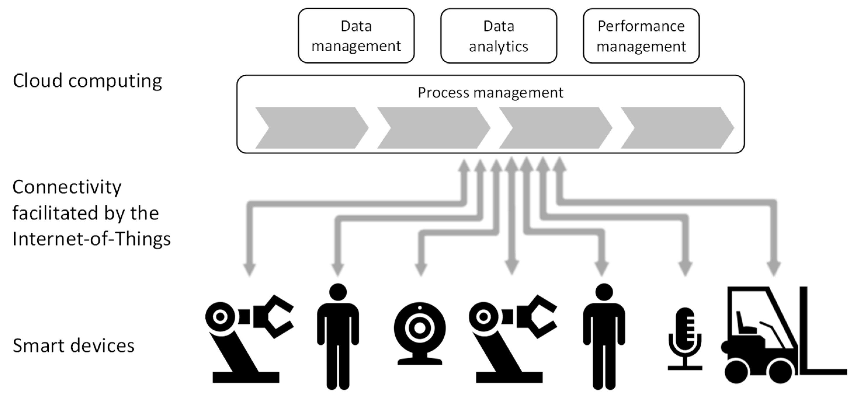
Industry 4.0 is a trend in automation and digitization that promises significant gains in production output, product customizability, and manufacturing flexibility [1]. This new industrial age stems from the coincident rise of cloud computing, the Internet-of-Things (IoT), and smart devices [2]. It is expected that mass customized products will be produced by smart robotics in dynamic processes managed in the cloud [3]. It is even conceptually understood how these technologies should work together to achieve smart manufacturing and deliver on the promises of Industry 4.0 [4,5]. Computation that is not time-critical is relegated to the cloud. The IoT facilitates commands and responses to and from devices and teams of humans and smart robotics perform sophisticated operations. Figure 1 gives an overview of the technologies and their roles in smart manufacturing.
The technologies that underpin Industry 4.0 are increasingly appealing and accessible to manufacturing enterprises. Cloud computing and internet connectivity is prevalent in industrialized countries and robots are becoming increasingly intelligent and affordable [6,7]. Future scenarios are proposed where humans and robots harmoniously collaborate to perform irregular and complicated tasks [8]. Even small and medium enterprises (SMEs) now consider user-friendly automation solutions. For example, a robot that can be programmed by a demonstration is significantly easier and inexpensive to introduce in a relatively low-tech environment [9].
Although more accessible, affordable, and available, these technologies are developed independently and remain largely detached. The separate technologies can be acquired and even implemented, but it is unclear how to unlock the promised benefit of an integrated solution. Monostori [10] argues that these new technologies threaten the traditional automation hierarchy, which further distorts our understanding of the manufacturing system and its various elements. Thus, the adoption of smart manufacturing technology is hindered by utilization and integration instead of acquisition. In fact, the absence of out-of-the-box solutions that combine the different technologies is considered a primary impediment on the path towards smart manufacturing [6].
The symptoms of the problem manifest most fervently on a factory floor with humans and robots. The activities of humans and robots are controlled differently. Humans receive written, oral, or visual instructions while machines are compelled to action via their control systems. These control regimes function independently [11], which makes it difficult to transfer tasks between humans and robots even if their capabilities would allow this [12,13]. Furthermore, robot control is often poorly integrated with cross-functional processes management [14]. Robot control follows a vertical orientation focused on the operations within a work cell. Process management follow a horizontal orientation focused on the operations across work cells and in the context of enterprise information processing. Thus, current robot control does not support simple reassignment of robots to different work cells. The most apparent symptom is the increased safety hazards introduced by automation. Robots must be equipped with extensive safety precautions to allow close collaboration with humans (the accident in a car factory [15] is well known in the domain). To compensate, human and robot working spaces are usually physically separated. These symptoms and concerns hamper mainstream adoption of human-robot collaboration technology [13,16].
The contribution of this paper is an architecture model of an information system that utilizes modern manufacturing technologies to deliver seamless integration between human and automated activities. The model is proposed as a reference architecture for a manufacturing operations management system for Industry 4.0. As reference architecture, it serves two purposes: (1) it frames the scientific inquiry and advancement of information systems for Industry 4.0 and (2) it can be used as a template or at least a starting point to develop commercial-grade manufacturing applications for Industry 4.0.
The information system model is developed as part of the HORSE Project, which is a European research and innovation project in the Horizon 2020 program [17]. The project brings together 22 organizations including research institutions, technology vendors, and manufacturing enterprises. The primary objective of the project is to make advanced manufacturing technology more accessible to SMEs. These technologies are packaged in a modular, integrated “HORSE System” and include human intention detection, robot force control, teaching-by-demonstration, augmented reality, dynamic allocation of tasks to humans and robots, and manufacturing process management. The intended SME context of the HORSE System often implies limited availability of on-site information technology resources. Therefore, the use of cloud services can be an important enabling factor in the application of HORSE concepts and technology in an SME.
This paper starts with a detailed explanation of the research approach derived from the Reference Architecture for Industry 4.0 (RAMI4.0) and the Kruchten 4 + 1 software engineering framework. In Section 3, the logical system architecture is presented at three levels of aggregation to give insight into the function and structure of the HORSE System. Thereafter, Section 4 presents the physical architecture of the HORSE System in two stages: first, determining which parts of the system can be located ‘in the cloud’ and, second, presenting the HORSE System as an IoT application. The consideration of cloud-support expands on earlier work of Grefen et al. [18]. In Section 5, three real-world scenarios are presented as proof of concept of the HORSE System. Section 6 considers the possibilities of cloud-based management of inter-organizational manufacturing processes and supply chains. Lastly, conclusions and findings are discussed in Section 7.
2. Research Approach
The information system architecture presented in this paper is the result of rigorous design and science research. The purpose of design science research is to generate prescriptive knowledge that can be used to solve practical problems [19]. As such, problems from the industry are studied to ensure practical relevance and an artefact is created to help solve similar problems. The artefact in this paper is in the form of a conceptual design of an information system [20] to serve as reference architecture to develop and build an information system for the management of smart manufacturing operations.
To structure the research, the design science research framework of Hevner et al. [21] is adopted and discussed in Section 2.1. More importantly, the design approach is thoroughly reported to ensure repeatability. A similar result should be achieved given the same problem and context. The design approach is documented in the form of principles and process. The principles that guide the design are based on information systems architecture theory and discussed in Section 2.2. The research process is based on the widely adopted Kruchten 4 + 1 framework for software engineering [22], which is explained in Section 2.3.
2.1. Research Framework
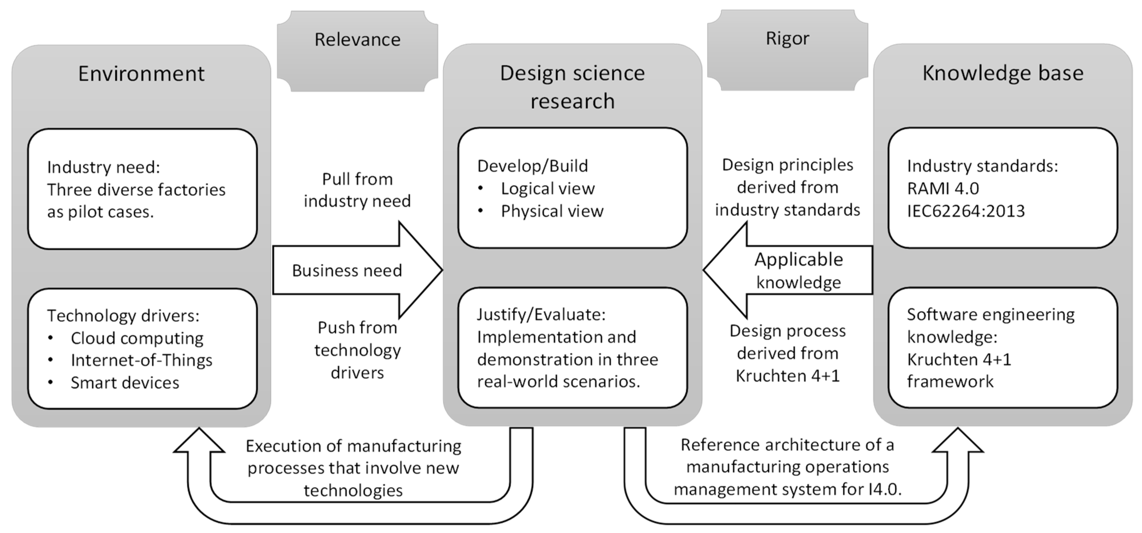
The HORSE System must be both practical and relevant for the typical challenges faced in SMEs. To achieve this goal, the design science research framework of Hevner et al. [21] is adopted. The framework emphasizes practical relevance by advocating for consideration of business need during the development and evaluation of the results in a realistic environment. The research framework, based on the Hevner et al. framework [21], is shown in Figure 2.
The design science research column of Figure 2 consists of development and evaluation. It produces validated reference architecture. The reference architecture is presented in a logical and physical view in Section 3 and Section 4, respectively, according to the Kruchten 4 + 1 framework. The remaining development and process views of the Kruchten framework are omitted in the interest of brevity. The evaluation is articulated in scenarios that demonstrate application of the information system. For relevance, three pilot cases act as the organizations that have the business need while three core concepts of Industry 4.0. provide the technology push driving the artifact development. The artifact is applied in the applicable environments of the three pilot cases, as articulated in the scenarios. For rigor, design principles are derived from industry standards and the design process is based on the Kruchten 4 + 1 framework. Lastly, the contribution toward the knowledge base is a validated information system model.
2.2. Design Principles
RAMI4.0 was established and defined in DIN SPEC 91345:2016-04 [23] to give some structure to the rapidly developing and changing technologies in manufacturing. According to the standard, “the fundamental purpose of Industrie 4.0 is to facilitate cooperation and collaboration between technical objects, which means they have to be virtually represented and connected.” The reference architecture brings together the business, life cycle, and hierarchical views of an asset by relating the concepts on three orthogonal dimensions [24]:
- The layers dimension is more formally referred to as the architecture axis. This axis “represents the information that is relevant to the role of an asset.” It covers the business-to-technology spectrum by relating different aspects of an asset to layers of the enterprise architecture.
- The life cycle and value stream dimension “represents the lifetime of an asset and the value-added process.” This axis distinguishes between the type and instance of the factory and its elements. For example, the digital design of a product and its instantiation as a manufactured product.
- The hierarchy levels dimension is used to “assign functional models to specific levels” of an enterprise. This axis uses aggregation to establish enterprise levels that range from the connected world (i.e., networks of manufacturing organizations in their eco-systems) via stations (manufacturing work cells) to devices and products.
The life cycle and value stream dimension of RAMI4.0 distinguishes between the type and instance of a product and its value-added processes [23]. Type can be equated to the design of the product and processes while instance is the execution of processes to produce a product. This separation emphasizes the importance of consistency across the product life cycle.
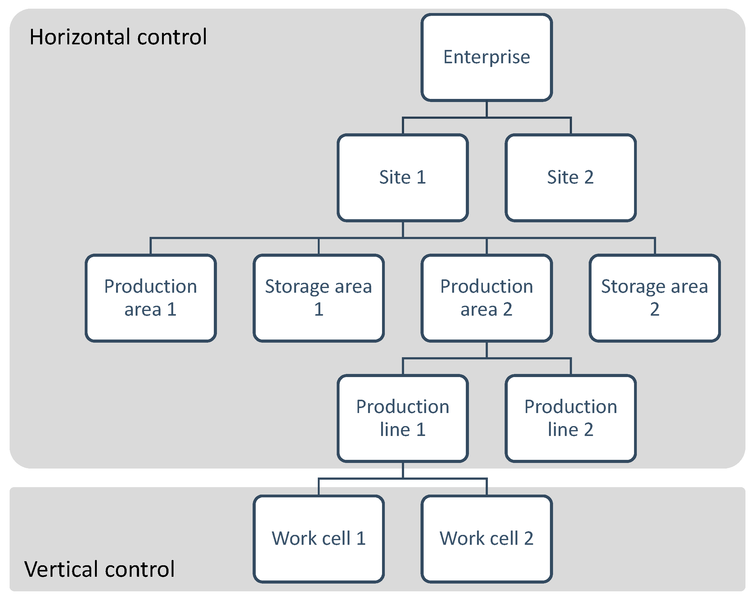
The hierarchy levels dimension of RAMI4.0 references the international standard IEC62264:2013 [25]. More specifically, the physical hierarchy of IEC62264:2013 is referenced. The physical hierarchy establishes a naming convention for the sections in the factory. Enterprise is the highest level of the hierarchy and work cell is the lowest for a discreet manufacturing facility. Figure 3 shows an illustrative physical hierarchy of a hypothetical manufacturing enterprise.
The separation of concerns is widely used to manage complexity in system design [26,27,28]. The technique allows the designer to consider some aspect of the system separately from the rest of the system, which decreases local complexity. We apply the technique to create two separations in the HORSE System derived from RAMI4.0 and apply these as design principles below.
- Separation between design-time and run-time system functions based on the life cycle and value stream dimension.
- Separation between horizontal and vertical control based on the hierarchy levels dimension.
The first separation between design-time and run-time is applied to both the manufacturing processes and the participants in those processes. Manufacturing processes and agents (the participants in the processes) are identified and described during the design period and then instantiated and activated to perform activities during the run-time.
The second separation between the horizontal and vertical control is derived from the physical hierarchy, which is shown in Figure 3. Horizontal control is concerned with the sequence of activities performed by several participants to transform materials into products, i.e., management of the manufacturing processes across multiple work cells. Vertical control is concerned with the actions performed by a single participant or a team of participants within a single work cell of the factory. The different control regimes are also indicated in Figure 3. Thus, horizontal and vertical control is separated to account for different control regimes. Horizontal control is concerned with the coordination of activities that may be spatially dispersed while vertical control is concerned with the sub-second synchronization of actions.
2.3. Design Process
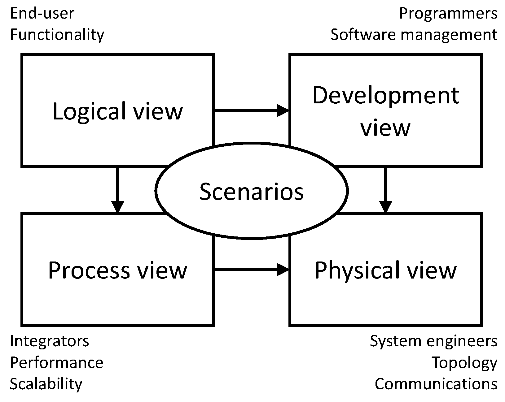
The HORSE System includes several disparate technologies and stresses the need for systematic development and sound architectural principles. The Kruchten 4 + 1 framework [22] is used to deal with the various views of stakeholders and their sequencing in time. The framework, as shown in Figure 4, employs phased development resulting in four views with their respective primary stakeholders.
- 1.
- The logical view is concerned with what the system should do. It specifies the functionality of the system in the form of modules and relationships between modules. The main stakeholders are the end users of the system.
- 2.
- The development view is concerned with good software management. It specifies how the software system is organized in a developmental environment. The main stakeholders are the software engineers.
- 3.
- The process view is concerned with the performance and scalability of the system. It specifies the concurrency and synchronization of the system modules. The main stakeholders are the integrators of the system.
- 4.
- The physical view is concerned with realization and deployment of the system. It specifies the allocation of hardware resources to software modules. The main stakeholders are the engineers who are responsible for installing and maintaining the system.
Separate views with different stakeholders can result in a divergence of ideas and an understanding about the system. To avoid such a divergence, the four views are reconciled by a fifth concept:
- 5.
- Scenarios represent user cases of the system that demonstrate system functionality and performance. The scenarios should be specific and practical enough to facilitate discussion about the expected operation of the system in its intended context.
The Kruchten 4 + 1 framework is used to sequence the development of the HORSE System. First, the logical architecture is used to specify the functional structure of the system without reference to specific implementation techniques, technologies, or deployment. The main input into this design is a clear description of the scenarios and the problems faced in those scenarios. The output of this phase is a logical architecture design with five aggregation levels along with one context level [29]. We discuss four of these six levels in Section 3 of this paper. The development and process views are concerned with a good software engineering practice and are, thus, omitted from this paper.
In the physical view, it is determined how and where the software resulting from the previous two views will run. The exact software and hardware may be different for each deployment of the HORSE System, but the type of technology remains the same. The exact software and hardware used in the HORSE Project is specified in this case study [30]. This research paper is more concerned with the separation between cloud-based and on-premise deployments. Thus, the cloud-supported parts of the HORSE System are identified, which leads to a clear division between the modules running ‘in the cloud’ and those running on premise. This division is discussed and justified in Section 4 of this paper based on performance and security considerations. The scenarios are located within the three industrial pilot cases of the project and discussed in Section 5.
3. Logical View of the HORSE System
The logical system architecture of the HORSE System is a hierarchical, multi-level view. The complete design comprises six levels of aggregation, but only the first four levels are discussed in this paper in the interest of brevity. The full system design report [29] elaborates on the remaining two levels of aggregation, but it limits the discussion to system structure and design decisions. Conversely, this research paper emphasizes scientific rigor and presents the HORSE System in the context of Industry 4.0. The four levels discussed in this paper are labeled Context Architecture and Architecture Levels 1, 2, and 3. The Level 2 architecture is divided into the design time half and the execution time half. Only the execution time subsystem on the local layer is discussed because this subsystem is the most complicated and is responsible for the main interface between software and hardware on the factory floor.
3.1. HORSE Context Architecture
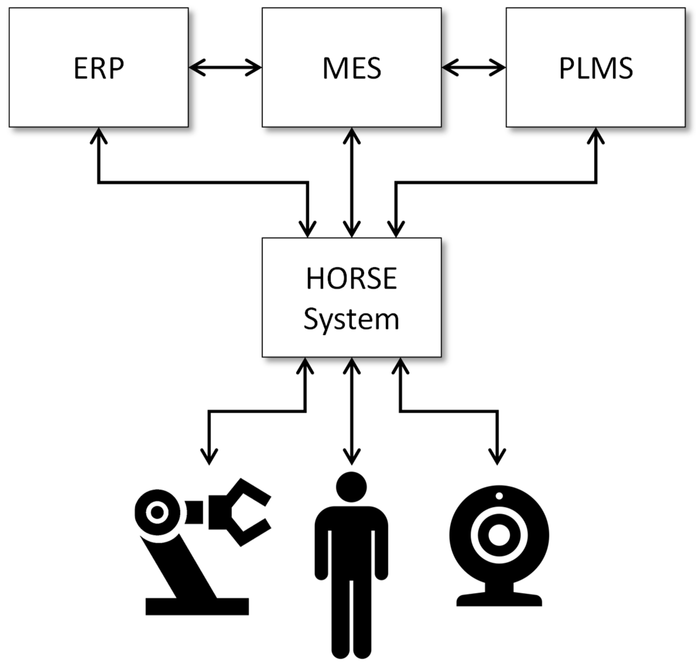
The HORSE System is primarily concerned with highly configurable, flexible manufacturing processes involving human and robotic participants. All three pilot cases in the HORSE Project, which are discussed in Section 5, feature processes with cooperation between humans and robots. Therefore, the HORSE System interfaces with a variety of humans, robots, and sensors that participate in the manufacturing processes. These processes do not exist in isolation. Any manufacturing enterprise also performs other business processes such as purchasing, product development, sales, and customer support. Consequently, the HORSE system must be contextualized in the existing hardware and software systems of the enterprise.
An illustrative enterprise architecture is shown in Figure 5 with the HORSE System positioned as a central hub amongst typical systems found in factories [14]. Business management systems are represented with an enterprise resource planning system (ERP), which is a manufacturing execution system (MES) and a product life-cycle management system (PLMS) at the top of Figure 5. Toward the lower end of Figure 5, the HORSE System is connected to a robot, human, and sensor, which promotes human-robot co-existence. In practice, the situation is typically more complicated, but this simplified view shows the context of the HORSE System.
3.2. HORSE System Architecture Level 1
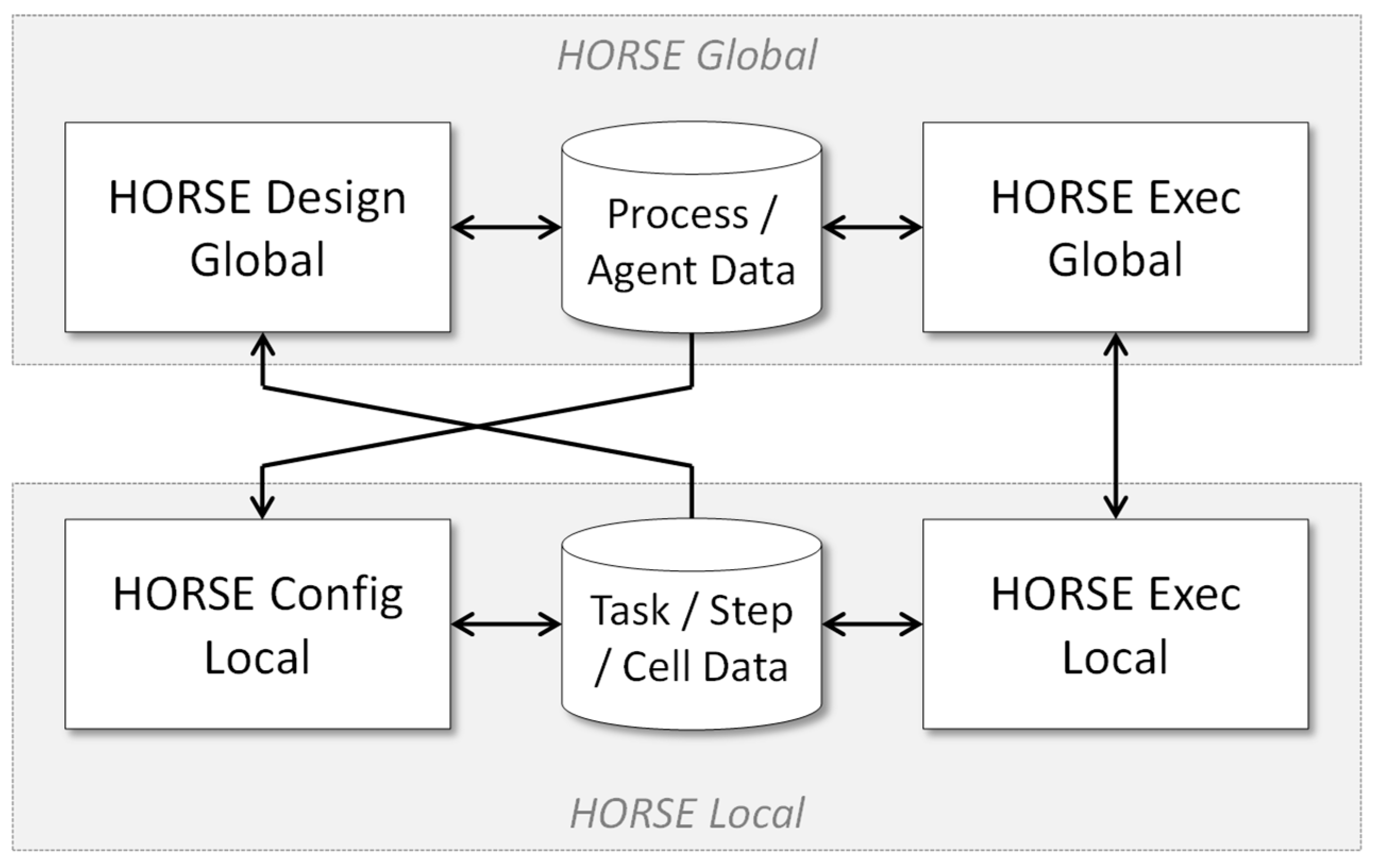
Level 1 of the architecture model unpacks the HORSE System box of Figure 5 to refine its contents. This refinement applies the two design principles described in Section 2.2: separation of design-time and run-time system functions and separation of horizontal and vertical control. The first design principle calls for system functionality dedicated to design and control, respectively. This consideration gives the architecture a columned style with a design-time column and an execution-time column. The second design principle calls for separation between functionality that is aimed at the support of activities within a single manufacturing work cell and functionality that is aimed at synchronizing activities across multiple work cells. This consideration gives the architecture a layered style with global and local control layers. The global layer interfaces with business management systems at the top of Figure 5 while the local layer interfaces with humans and robot controllers, which is shown at the bottom of Figure 5.
Applying the two design principles results in a system architecture with four sub-systems and two data stores, as shown in Figure 6. This is a columned architecture embedded in a layered architecture [31]. The design-time and execution-time columns are connected via databases that contain specifications of manufacturing activities and the participants involved in the activities. During design-time, the global and local layers are indirectly connected via the data stores since these subsystems are used to create and edit the manufacturing activities and actors. However, for execution time, HORSE Exec Global and HORSE Exec Local are directly coupled to pass messages directly between global and local control. Note that the design-time subsystem on the local layer is labeled as configuration instead of design, since this fits better with the configuration of equipment and tools within work cells.
In the two subsections below, the HORSE system architecture is further elaborated. The design period and execution time columns of Figure 6 are discussed separately to manage the inherent complexity of the system.
3.3. HORSE Design Time Architecture Level 2
This section elaborates on the design-time column of the HORSE System, which is shown in Figure 7. On the global layer, the HORSE Design Global subsystem provides functionality to design manufacturing processes across multiple work cells populated by multiple, possibly heterogenous, actors. As such, the subsystem contains two modules dedicated to the design of processes and agents (terminology used to denote any independent process participant), respectively. For the Process Design module, existing business process management (BPM) technology is used as the basis and extended to accommodate the physical nature of manufacturing processes as opposed to the administrative processes for which this technology is traditionally used [32]. Most significantly, the location of manufacturing operations must be considered to accommodate the time it takes for material to flow between locations. The Agent Design module is a graphical user interface that enables the user to create new agent profiles or edit existing agent profiles. Such a profile comprises attributes that describe the agent including abilities, skills, authorization, cost, and performance.
HORSE Config Local provides functionality for defining the operations performed within a work cell. The terminology of ‘task’ and ‘step’ is used here to distinguish between the actions of multiple and single agents. The task design module is used to specify the synchronization of a team of agents within a work cell like the interplay between a human worker and a robot. The actions performed by the individual members of a team are specified using the two-step design modules. The human step design module is used to create work instructions. These work instructions may range from simple textual descriptions to technology-supported guidance like augmented reality. The automated agent step design module is used to create execution scripts for robot, automated guided vehicles or any other non-human agents. Several different instances of this module may exist in the same enterprise, which corresponds to the different types of automated agents used and supports textual scripting, graphical scripting, and scripting by physical manipulation (physically showing the robot what to do, which is also called programming by demonstration [9]). The latter requires a direct connection to the involved robot, which is shown in Figure 7. Lastly, the work cell simulator module is used to digitally define and evaluate the physical constraints within which a task will be executed. Physical constraints may include inter alia, the space available for agents to move, the location of the work cell, and the mounted position of the automated agents.
3.4. HORSE Execution Time Architecture Level 2
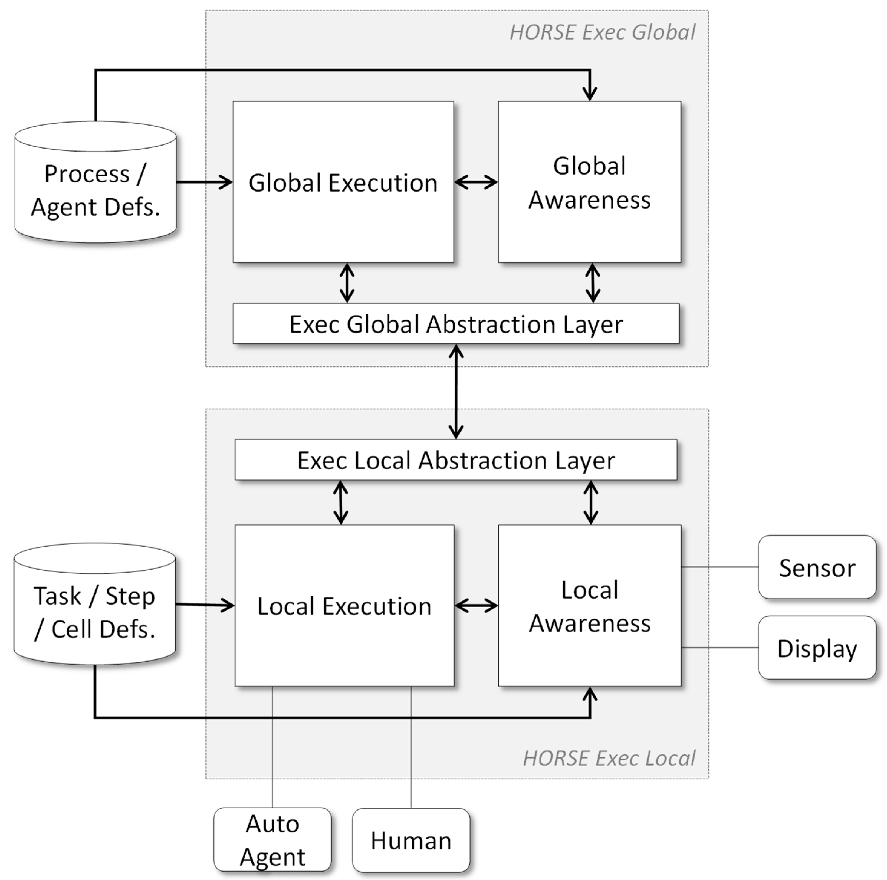
This section elaborates the execution-time column of the HORSE System, as shown in Figure 8. Within the global and local layers, each contain an execution and an awareness module. HORSE Exec Global provides the functionality to enact and monitor manufacturing processes across multiple work cells. Analogous to global design subsystem, the HORSE Exec Global subsystem is based on BPM technology with extensions to make it suitable for manufacturing processes [33].
HORSE Exec Local provides the functionality to control and monitor the activities of a team of agents in a single work cell (a team may be only one agent). This subsystem directly interacts with agents by sending commands and receiving responses. The interaction differs between humans and automated agents. Work instructions are displayed on handheld devices or fixed monitors and responses are received via physical or virtual buttons. For example, an operator may receive the instruction to perform a task via an instant message. Once at the station, the augmented reality guidance is displayed via the local awareness module and hand movements are detected via a sensor. Automated agents receive execution scripts and respond according to predefined parameters. The Local Awareness module is concerned with regular activity monitoring and exception detection.
An instance of HORSE Exec Local is created for each team formed to perform a task. Therefore, multiple instances of the subsystem may exist at the same time and may even build on different technology platforms. The abstraction layers facilitate the communication between the HORSE Exec Global and multiple instances of HORSE Exec Local. Integration between the global and local layers, as facilitated by the abstraction layers, is illustrated with a video available on the project website (http://www.horse-project.eu/Media). The HORSE Exec Local subsystem is discussed in more detail in Section 3.5.
3.5. HORSE Exec Local at Aggregation Level 3
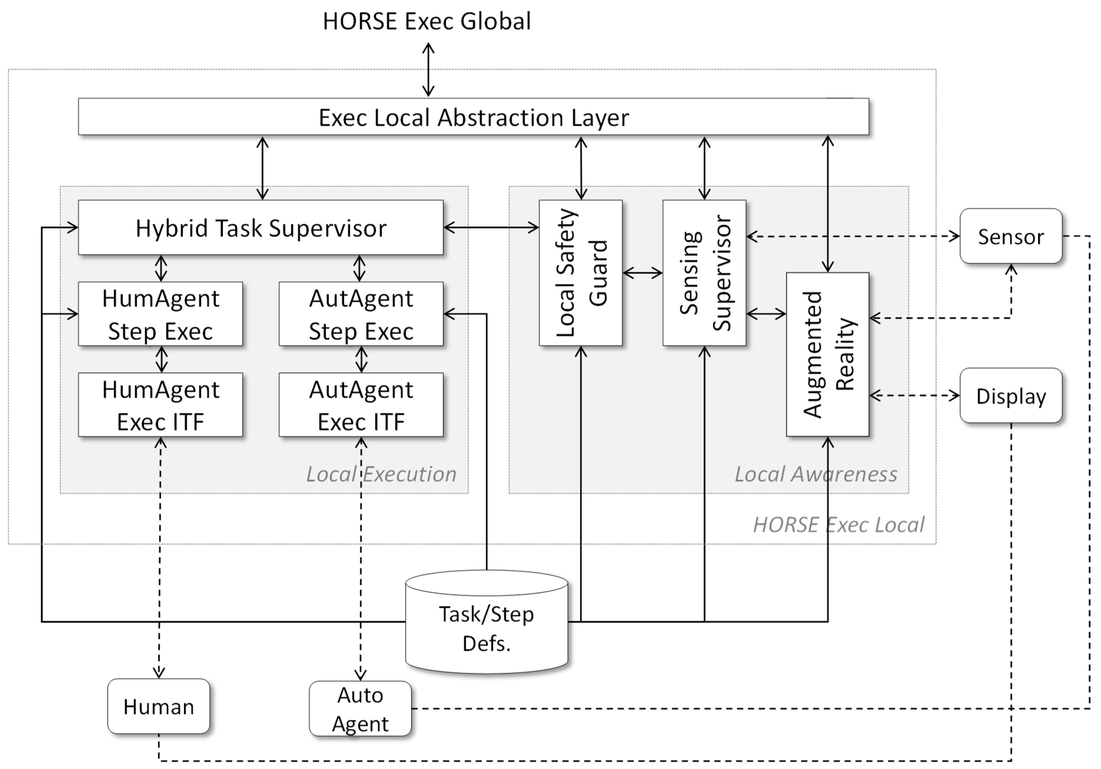
Figure 9 shows the refinement of the HORSE Exec Local system module at aggregation level 3. It is, in this part of the HORSE architecture, that the cyber-physical character of the system becomes most apparent because this subsystem is responsible for the real-time control of physical agents.
The Local Execution module, as shown on the left side of Figure 9, is responsible for driving the execution of manufacturing tasks. The Hybrid Task Supervisor module delivers the human-robot collaboration capability of the HORSE System. The module controls synchronize the actions of multiple human and/or robotic workers (in HORSE terminology, human agents and automated agents, respectively). These workers receive their instructions via Step Execution modules that manage individual work steps for individual agents and Execution Interfaces that abstract from specific agent control characteristics (such as specific robot control interfaces). Local Execution implements actuation controls from an IoT perspective.
The Local Awareness module, on the right side of Figure 9, is responsible for monitoring the work cell. This module is coupled to sensors and cameras in the work cell that provide real-time information about the status of the work cell such as the position of robotic arms and manipulated products. These sensors and cameras may be attached to robots such as for measuring torque or applying pressure sensors on robot arms. Part of this information can be fed to displays that provide information to human workers. Local Awareness implements sensing controls from an IoT perspective.
4. Physical View of the HORSE System
The logical view of the HORSE System architecture is explained in Section 3. In this section, the physical view of the Kruchten 4 + 1 framework is applied. The goal of this section is to analyze the role of Industry 4.0 technologies in the HORSE System instead of specifying the actual hardware, infrastructure, and physical systems. Given the primary context of small and medium manufacturing enterprises, it is first determined, in Section 4.1, which modules of the system can be situated in the cloud. Since the design time sub-system and the execution time sub-system of the HORSE system have very different technical requirements, we perform this analysis per sub-system. This analysis naturally establishes the divide between the cloud-supported modules of the system and the Things on the factory floor. The divide is used to construct an IoT-view of the HORSE System, which is presented in Section 4.2.
4.1. Cloud Support for the HORSE System
To determine which modules of the HORSE System can be hosted in the cloud, we consider the performance expectations of various modules. For example, modules used during the design period generally do not require guaranteed sub-second response times. Hence, such modules can be hosted as cloud applications and be subjected to the normal performance impact of distance and Internet traffic. To add some nuance to the discussion, we distinguish between two cloud-based models and a non-cloud model for software deployment [34].
- The Software-as-a-Service (SaaS) model provides a software application as a hosted service on the Internet, eliminating the need to install and run the application on local computers.
- The Platform-as-a-Service (PaaS) model provides an application environment in which users can create their own application that will run on the cloud.
- The on-premise model represents traditional computing with no part of the software or computer hardware hosted in the cloud.
Rimal et al. [35] advocates for scalability, performance, multi-tenancy, configurability, and fault-tolerance as the primary considerations for cloud support of applications. Table 1 lists the advantages and disadvantages inherent to each cloud-support model in relation to the five considerations.
We apply the five considerations listed in Table 1 to determine which modules of the HORSE System can be hosted with the SaaS or PaaS cloud computing models. The results of the analysis are listed in Table 2.
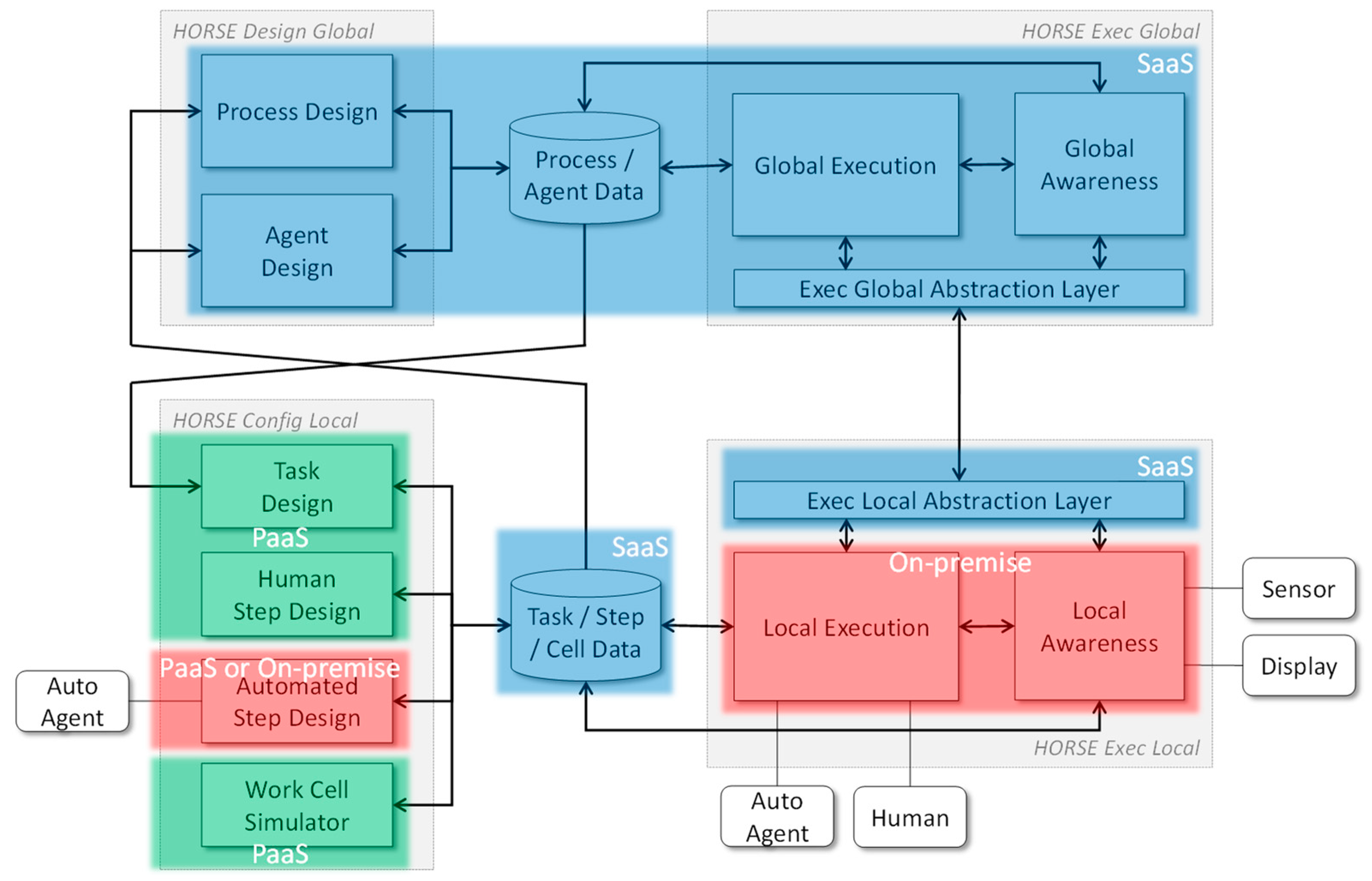
Figure 10 shows the result of the five considerations as an overlay on the logical view of the HORSE System architecture. The modules at the global layer support process design, agent design, process enactment, and monitoring. Process and agent design are interactive modules but do require any guaranteed performance. A further advantage of the SaaS model is simplified versioning and upgrade of the software since manufacturing is becoming more flexible [36,37]. Process enactment and monitoring has a real-time character but without very strict timing requirements. Consequently, it is possible to deploy all global layer modules and both the data stores in the cloud. An important requirement for the cloud environment is a very high quality of service (QoS) in terms of availability: unavailability of global functionality typically brings a process-oriented manufacturing plant to a halt within minutes if not seconds.
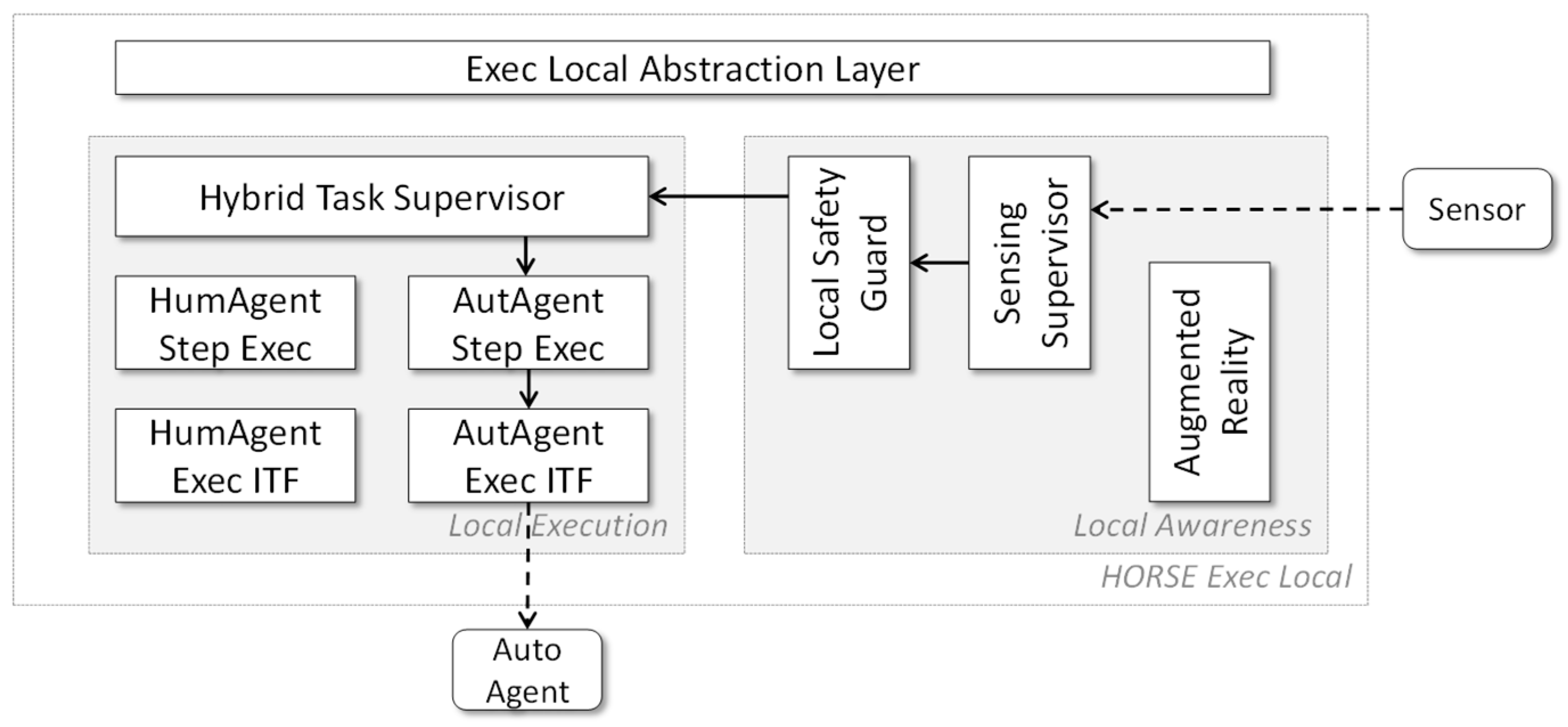
The modules at the local layer control the activities of agents—either individually or in teams—are very much real-time cyber-physical systems. This means that part of their functionality has very strict response-time requirements. A good example is safety management, which requires fast synchronization between sensors, local awareness functionality, local execution functionality, and agents (humans and robots). Figure 11 shows the communication path in the system (as a simplified view of Figure 9 to make things clearer) when a human agent enters the operating space of a robotic agent and the robotic agent must immediately stop.
4.2. The HORSE System as an IoT Application
With HORSE Exec Global in the cloud and HORSE Exec Local on-site, the HORSE System relies heavily on communication between the cloud and the Things that perform manufacturing activities. Significant disagreement exists regarding the nature and scope of the IoT [38], but Wortmann and Flüchter [39] offer a complete overview of the concept by bringing together computing, connectivity, and devices in a single technology stack. The technology stack follows the concept of functional abstraction [31], i.e., each layer builds on the functionality of the layer below. For example, the control software of a thing/device makes use of the actuating and sensing components to exert control over the hardware of the thing/device.
The technology stack draws attention to the division between the things or devices (including its embedded control system) on the factory floor and software situated in the IoT cloud. The connectivity layer facilitates communication between the IoT Cloud and one or more things/devices.
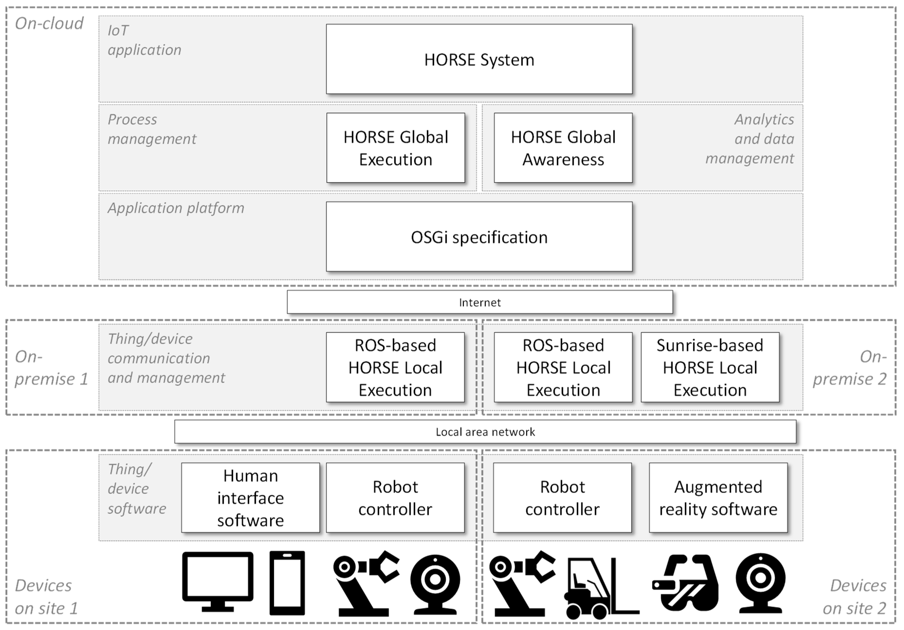
Functional abstraction and the division between the cloud and the device is applied to construct a technology stack for the HORSE System. The resulting technology stack, which is shown in Figure 12, serves two purposes: (1) to describe how modern technologies contribute to realize the HORSE System and (2) to justify the designation of the HORSE System as an IoT application.
Starting from the bottom of Figure 12, to simplify the explanation of the assimilation of technologies, the various things and devices are shown as simple icons. Human interfaces are represented with displays and handheld devices. The sensors are represented with a camera and microphone while robots are represented with a robotic arm and a vehicle. Lastly, augmented reality is represented with wearable glasses and a sensor to track human movements. The distinction between hardware and components is omitted here because it adds no value to the current discussion. The displayed things or devices are only representative since the actual set may differ in a factory. On the second layer from the bottom, the various devices and things are controlled by their respective software systems. These software systems are left purposefully abstract to signify the open nature of the HORSE System. Many different technologies can be utilized in conjunction with the HORSE System. The software systems of the devices are connected to the HORSE System via the local area network of the factory.
The HORSE Local Execution subsystem serves as thing/device communication and management. This is the most significant deviation from the IoT technology stack of Wortmann and Flüchter [39]. The thing/device communication and management is not included in the Cloud grouping of the technology stack because of the requirement for guaranteed, sub-second communication and synchronization between teams of agents, which is discussed in Section 3.4. The HORSE System currently has two realizations of the Local Execution subsystem based on the Robot Operating System (ROS) and Kuka Sunrise software, respectively. Both these variations can control various technologies involved in smart manufacturing processes and can even be deployed simultaneously in the same factory.
A singular block named Internet is shown to represent the connectivity between Local and Global features. This implies all standard infrastructure and protocols because the current realization of the HORSE System uses standard internet protocols to transport JavaScript Object Notation (JSON) messages. These messages are directed via the message bus of the Open Services Gateway initiative (OSGi) application platform, which allows all subsystems of the HORSE System to subscribe to it and publish messages. The OSGi application platform ties in well with the PaaS model, which is explained in Section 4.1. With an OSGi-based platform and accompanying computing resources hosted in the cloud, the user can install a variety of thing/device communication and management systems based on different technologies to control the activities of different robots and sensors.
HORSE Global Execution, which represents the process management technology, publishes messages and subscribes to listen for responses. Similarly, the HORSE Global Awareness subsystem represents the data analytics technology by listening for various pre-defined events that may indicate unwanted or unexpected factory floor conditions. Thus, the HORSE System is an IoT application with multiple layers of functionality covering the complete technology stack of Wortmann and Flüchter [39].
5. Scenarios as Proof of Concept
The HORSE System is positioned as a manufacturing operations management system for Industry 4.0. Therefore, it is claimed that the HORSE System can be used to manage operations that involve modern manufacturing technologies. To substantiate this claim, manufacturing processes that utilize the smart technologies are demonstrated to serve as proof of concept of the HORSE System. For each process, the involvement and role of various technologies are highlighted in the process models and are subsequently discussed.
The three pilot cases considered in the HORSE Project represent a wide range of problems encountered in the manufacturing industry. These pilot cases are analyzed to articulate clear scenarios where smart manufacturing technology is applied to solve common problems. Each scenario is described to give context, represented as a process model, and demonstrated with video footage.
5.1. Pilot Case 1: Tool Assembly
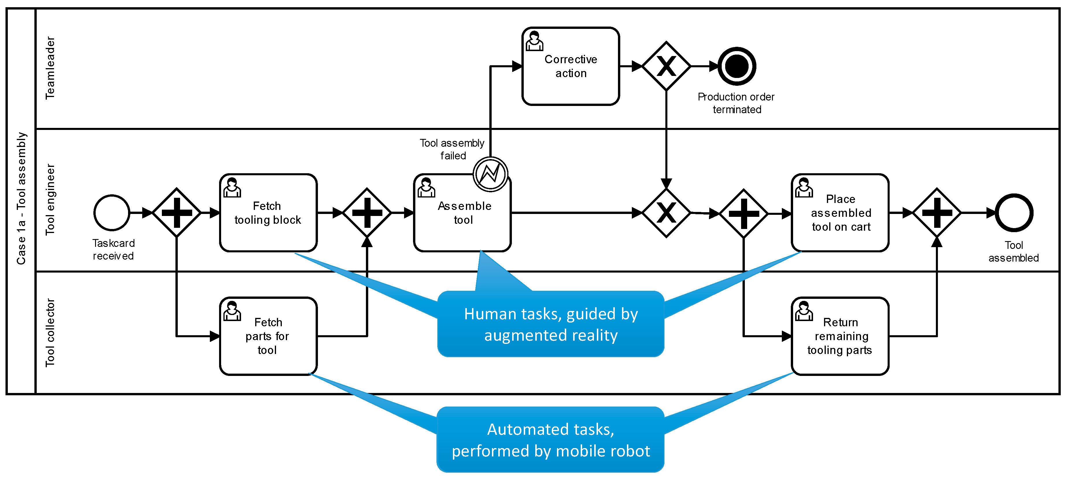
The first pilot site of the HORSE Project is a medium-sized factory in The Netherlands that produces highly configurable metal products used in furniture assembly. The pilot case features two processes including tool assembly and surface treatment of metal profiles. The first process involves a human operator who attaches tool parts to a base-plate to assemble a configurable tool used for deformation operations. In parallel, a mobile robotic arm fetches bins containing the parts needed by the operator. To alleviate the complication and variability of the assembly task, the human assists by augmented reality technology that highlights which parts are needed and how to attach those parts. The model of this process is specified using the Business Process Model & Notation 2.0 (BPMN2.0) and shown in Figure 13. Video footage of the executed process with augmented reality and robotic support is available online (https://youtu.be/bqTDEZvOdVI).
The model shown in Figure 13 is created using the Design Global subsystem of the HORSE System (see Section 3.3). Thereafter, the process model is parsed by the Global Execution to enact the process during the demonstration. Tasks, as specified in the process model, are globally instantiated and assigned to agents. The task instructions are sent to the Exec Local subsystem via the message bus. The Exec Local subsystem ensures synchronization between the robot and human and is guided by augmented reality.
The full stack of technology, as shown in Figure 12, is utilized to execute the tool assembly process. As a summary, the various technologies have the following roles in the process.
- Cloud-based process management to coordinate the activities of human and automated agents.
- IoT-enabled connectivity between cloud-based process management and multiple production agents.
- Augmented reality to guide the human agent through the tool assembly steps.
- Smart robotics to fetch and return tooling parts from the storage zone.
Pilot case 1 is a particularly compelling case for the HORSE Project because it is not a simple replacement of a human operator with a robot. Instead, the operations are granularized to determine which activities are more suited to human or robot execution. The cognitive and sensory abilities of the human are exploited for the complicated assembly task, but the monotonous fetching and returning tasks are allocated to a mobile robot. Therefore, instead of being replaced by automation, the human is rather supported by automation and allowed to focus on the task that requires deep concentration, which increases process throughput.
The primary limitation in this pilot case is related to the definition of augmented reality tasks. The images and instructions displayed during augmented reality supported tool assembly are currently manually programmed for a particular subset of tool configurations. This is perfectly adequate for demonstration purposes in a research and innovation project, but it must be simplified or at least streamlined for commercial purposes.
5.2. Pilot Case 2: Final Assembly of Automotive Parts
The second pilot site of the HORSE Project is a medium-sized factory in Spain that assembles highly customizable automotive parts. The case includes the final inspection and packaging of the assemblies before distribution to customers. The process involves three agents: (1) a robotic arm to pick up an assembly from the conveyor belt, present it for inspection, and, if accepted, place it in a box, (2) a sophisticated, bespoke camera system to inspect the assemblies, and (3) a human operator to evaluate assemblies flagged by the camera system to determine whether to discard or repair it. To deal with the complication of inspecting mass customized products, the human operator is assisted by an augmented reality system that indicates where and what the operator should inspect. Figure 14 shows the model used to enact the process of the second pilot case. Additional information and photos of pilot case 2 in operation are available online (http://www.horse-project.eu/Pilot-Experiment-1).
As can be seen from the lanes in Figure 14, the process involves four different roles, which are potentially performed by as many agents. The following technology is involved in this process.
- Cloud-based process management across multiple work cells.
- IoT-enabled connectivity between cloud-based process management and multiple production agents.
- Synchronized collaboration between smart robot and camera system to detect product defects.
- Augmented reality to guide the human agent with an inspection of highly customizable assemblies.
Pilot case 2 is a complex scenario involving four process participants and various eventualities that affect process execution. Communication from the factory floor is of utmost importance here to allow the HORSE System, track progress, and adjust accordingly. Communication is facilitated by handheld devices and sensors connected to the local network. The most compelling part of pilot case 2 is the human-robot collaborative task to inspect assemblies that are flagged as defective by the camera system. The Hybrid Task Supervisor module (see Section 3.5), in this case, is realized as a ROS application and uses state-machine models to synchronize the actions of the human and robot.
As with the first pilot case, pilot case 2 involves automation of some tasks in the process. Picking and placing is automated, but a human operator is still necessary to respond to detected defects and ensure that packaging material is available. This automation is beneficial but constraining. It is beneficial to the health of the human because the repetitive lifting and manipulation of heavy parts is eliminated. However, the robot can only handle one assembly at a time, which forces it to wait for the human if he or she is not immediately available. Therefore, the introduction of the HORSE System and associated smart technologies, in this case, improves operator health but not necessarily process performance.
5.3. Pilot Case 3: Separation of Castings
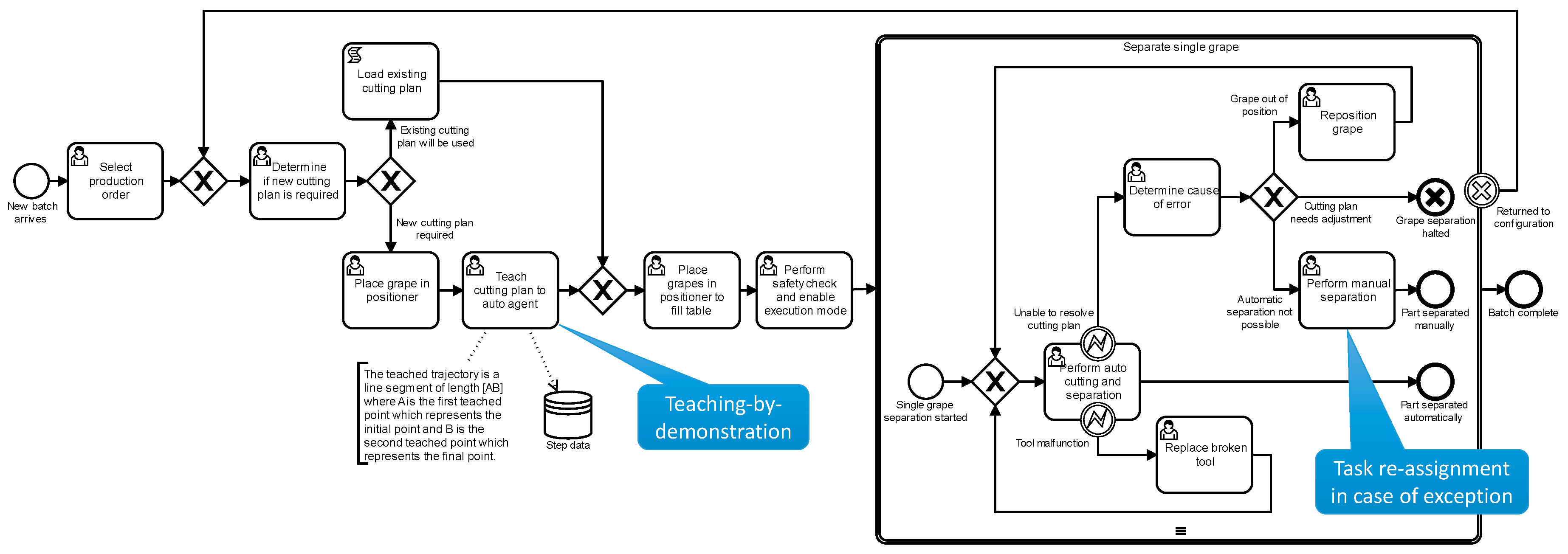
The third pilot site of the HORSE Project is a large foundry in Poland. The foundry uses sand casting to produce a large range of products for several industries including automotive, rail transport, and industrial equipment. Due to excess metal in the mold, four to eight castings are physically attached to each other after solidification. Those castings must be separated before further surface processing is performed. The separation can be automated. However, the high customizability of the product makes it infeasible to define cutting plans for all products. Each production run is ostensibly unique and, therefore, necessitates a new cutting plan. To handle such high product variability, a robot equipped with teaching-by-demonstration technology is deployed to lift some of the human operator. The operator physically moves the arm and the end-effector of the robot through the necessary cutting trajectories to teach the cutting plan instead of labor intensive approaches such as computer-aided manufacturing modeling or programming. Once the cutting plan is recorded, then the operator enables an execution mode to process the batch of products. Figure 15 shows the model used to enact the grape separation process, which highlights the teaching-by-demonstration task. Additional information and photos of pilot case 2 in operation are available online (http://www.horse-project.eu/Pilot-Experiment-2).
Although teaching-by-demonstration is the most noticeable feature of this process, several other technologies contribute to such a smart manufacturing process. The following technologies are involved in this process.
- Cloud-based process management to invoke the actions of humans, robots, and computer services.
- IoT-enabled connectivity between cloud-based process management and multiple production agents.
- Synchronized collaboration between human and robot during the teaching-by-demonstration task.
- Smart robotics with human intrusion detection to halt the execution in the case of safety risks.
Pilot case 3 is a clear demonstration of smart manufacturing with the utilization of teaching-by-demonstration and modern process management technology. More importantly, these technologies are demonstrated in an environment that is not particularly conducive to sophisticated and delicate computer systems. The factory floor is teaming with fine dust particles from the grinding operations. In this case, the cloud-based nature of the HORSE System proves valuable because only the robot is exposed to the dusty environment. However, this proves to be a limiting factor as well because the operator does not have access to any troubleshooting functionality. If something goes wrong, production management must be contacted to address the problem. Thus, Industry 4.0 technologies present many opportunities but also many new considerations when deploying smart technologies.
6. Inter-Organizational Process Perspective
Thus far, we explored how parts of the HORSE system can be deployed to achieve advantages in software management and computing infrastructure investments, i.e., advantages that do not influence the nature of the functionality offered. The focus of these developments is within one manufacturing enterprise. However, the technology employed in the HORSE System may offer improved functionality: cloud computing and the IoT can improve interoperability within manufacturing networks where a manufacturing process takes place across multiple sites or even autonomous enterprises.
Software modules that are used in a SaaS paradigm are typically of a standardized kind so that the same functionality can be used by multiple parties. Applying functional standardization to the modules at the global layer of the HORSE System in the context of multiple manufacturing enterprises that collaborate can improve interoperability between those enterprises. Consequently, it may be simpler to set up supply chains or supply networks with automated support for manufacturing processes (and related enterprise processes as discussed in Section 3.1) across enterprises. The current realization of the global layer of the HORSE System is run as a single application instance with multiple tenants for the three pilot cases. While the current pilot cases do not participate in the same supply chain, it does prove the feasibility of a single global layer serving multiple instances of the local layer across geographically separated sites. Figure 16 shows an expansion of the HORSE technology stack (see Figure 12) to include two sites with a different, illustrative set of things/devices.
Cross-organizational manufacturing is an ongoing research topic due to its numerous potential benefits [40,41]. The concept has been demonstrated in the CrossWork project [42,43], albeit without complete vertical integration down to the factory floor as in the HORSE project. In the CrossWork project, multiple manufacturing enterprises in the same supply chain network use a single, centralized process management system to synchronize their activities. These connected enterprises temporarily form an instant virtual enterprise, i.e., non-permanent collaborations with the sole purpose of producing a single product series. The CrossWork approach has been prototyped in the automotive industry, which provides a similarity with one of the pilot cases of the HORSE project. The CrossWork concept is illustrated in Figure 17 and it shows a global process that flows across four autonomous enterprises in a single supply chain network [42,43].
An alternative approach that allows more distribution of autonomy is the use of a multi-tenant SaaS process management solution that embodies the global execution module of HORSE for several enterprises in a chain and that also synchronizes the links between their manufacturing processes. Both alternatives lead to networked process management [44]. This is a relevant development since inter-organizational processes in manufacturing are receiving more attention in an Industry 4.0 setting [45,46]. This trend is required because of increasing product complexity, increasing producer specialization, and increasing mass customization of products [1].
7. Conclusions
This paper outlines the architecture design of the HORSE System. It is shown how structured, hierarchical design produces a modular architecture with clearly defined subsystems and interfaces. The system embodies the assimilation of traditional enterprise information systems (e.g., explicit process management) and advanced manufacturing technology (e.g., human-robot collaboration and the IoT). The HORSE System architecture is proposed as a reference architecture for a manufacturing operations management system for Industry 4.0. Thus, the architecture model of the HORSE System serves two purposes: (1) it can be used as a template or framework to position and develop a commercial-grade manufacturing operations management system for Industry 4.0 and (2) it helps frame the scientific inquiry into the management of manufacturing operations involving cloud computing, the IoT, and smart devices.
The proposed reference architecture model is the main contribution of this paper. Due to its complexity, it is presented and discussed in two views including the logical and physical views. The logical view details the functional operation of the system without any commitment to specific technologies. The logical view is elaborated at four levels of aggregation (two additional levels are covered in the full design report [29]). The physical view explores how the various technologies enabling Industry 4.0 are used to realize the HORSE System. Each module of the system is considered in order to determine whether it can be hosted in the cloud. To summarize, we show the leading drivers for cloud deployment for each of the four HORSE main sub-systems (as in Figure 6) in Table 3.
The HORSE System has three notable embedded characteristics that have potential advantages and disadvantages. First, cloud computing is emphasized as a fundamental enabling technology of the system. Cloud-based software lowers the barriers-to-entry for Industry 4.0. SMEs can focus on the use of smart devices to solve problems on the factory floor instead of being concerned with the installation and maintenance of software for those smart devices. However, cloud-based software especially with the SaaS model limits the flexibility available to SMEs. It is more time-consuming or expensive to make changes to a SaaS application than an application entirely under the control of the enterprise.
Second, the execution-time subsystem of the local layer of the system delivers real-time, sub-second synchronization between humans and robots. The time-critical nature of human-robot collaboration results in a clear separation between the cloud-based modules and modules for direct control of the things/devices on the factory floor. This separation contributes to the modular nature of the reference architecture and allows for technology heterogeneity on the factory floor. Multiple instances of local execution can be realized with different technology underpinnings. However, the separation places further importance on the reliability of Internet connectivity. If the cloud-based or Internet connectivity services are unavailable, all operations will be uncoordinated at best or suspended at worst.
Lastly, cross-functional, configurable manufacturing process management opens new ways for smart manufacturing by supporting flexible process definitions, dynamic allocation of tasks to human and robotic workers, and real-time coupling of work cell events for manufacturing processes. Such process management processes also hold promise beyond a single site or enterprise. Cloud-based process management supports improved interoperability in manufacturing chains and networks.
The HORSE Project is still ongoing and seeks to further enhance the system that bears its name. The design science research approach adopted in the project ensures practical relevance but it also increases the risk of overlooked problems or missed opportunities. The system design is informed by the real-world problems encountered by the three pilot cases and every attempt is made to extrapolate to more general problems. However, completely unrelated problems may exist in other factories, which may not be considered in the HORSE Project. Seven additional cases were subsequently added to the HORSE Project to evaluate the effectiveness of the HORSE System and to identify any shortcomings.
Lastly, as a research and innovation project, the HORSE Project did not create a commercial-grade manufacturing operations management system. Instead, a prototype was developed and implemented to demonstrate the feasibility of a system incorporating cloud computing, the Internet-of-things, and smart devices. Further complications will undoubtedly arise on the quest for a commercial-grade system, but, at least, the current system architecture can serve as a proven template for such a development.
Author Contributions
Conceptualization, J.E. and P.G. Funding acquisition, P.G. and I.V. Investigation, J.E., P.G., and I.V. Methodology, J.E. and P.G. Project administration, I.V. Software, J.E. and K.T. Validation, J.E. and K.T. Visualization, J.E. Writing—original draft, J.E. and P.G. Writing—review & editing, I.V. and K.T.
Funding
The HORSE project received funding from the European Union’s Horizon 2020 Research and Innovation Program under Grant Agreement No. 680734.
Acknowledgments
All members of the HORSE Architecture Team are acknowledged for their contribution to the system design process.
Conflicts of Interest
The authors declare no conflict of interest.
References
- Hofmann, E.; Rüsch, M. Industry 4.0 and the current status as well as future prospects on logistics. Comput. Ind. 2017, 89, 23–34. [Google Scholar] [CrossRef]
- Lu, Y. Industry 4.0: A survey on technologies, applications and open research issues. J. Ind. Inf. Integr. 2017, 6, 1–10. [Google Scholar] [CrossRef]
- Zhang, L.; Luo, Y.; Tao, F.; Li, B.H.; Ren, L.; Zhang, X.; Guo, H.; Cheng, Y.; Hu, A.; Liu, Y. Cloud manufacturing: A new manufacturing paradigm. Enterp. Inf. Syst. 2014, 8, 167–187. [Google Scholar] [CrossRef]
- Tao, F.; Qi, Q. New IT Driven Service-Oriented Smart Manufacturing: Framework and Characteristics. IEEE Trans. Syst. Man Cybern. Syst. 2018, 1–11. [Google Scholar] [CrossRef]
- Qu, T.; Lei, S.P.; Wang, Z.Z.; Nie, D.X.; Chen, X.; Huang, G.Q. IoT-based real-time production logistics synchronization system under smart cloud manufacturing. Int. J. Adv. Manuf. Technol. 2016, 84, 147–164. [Google Scholar] [CrossRef]
- Kang, H.S.; Lee, J.Y.; Choi, S.; Kim, H.; Park, J.H.; Son, J.Y.; Kim, B.H.; Noh, S.D. Smart manufacturing: Past research, present findings, and future directions. Int. J. Precis. Eng. Manuf.-Green Technol. 2016, 3, 111–128. [Google Scholar] [CrossRef]
- Lucke, D.; Constantinescu, C.; Westkämper, E. Smart Factory—A Step towards the Next Generation of Manufacturing. In Proceedings of the Manufacturing Systems and Technologies for the New Frontier, 41st CIRP Conference on Manufacturing Systems, Tokyo, Japan, 26–28 May 2008. [Google Scholar]
- Marvel, J.A.; Falco, J.; Marstio, I. Characterizing Task-Based Human–Robot Collaboration Safety in Manufacturing. IEEE Trans. Syst. Man Cybern. Syst. 2015, 45, 260–275. [Google Scholar] [CrossRef]
- Dillmann, R.; Friedrich, H. Programming by demonstration: A machine learning approach to support skill acquisition for robots. In Artificial Intelligence and Symbolic Mathematical Computation; Calmet, J., Campbell, J.A., Pfalzgraf, J., Eds.; Lecture Notes in Computer Science; Springer: Berlin, Germany, 1996; Volume 1138, pp. 87–108. [Google Scholar]
- Monostori, L. Cyber-physical Production Systems: Roots, Expectations and R&D Challenges. Procedia CIRP 2014, 17, 9–13. [Google Scholar] [CrossRef] [Green Version]
- Tsarouchi, P.; Makris, S.; Chryssolouris, G. Human–robot interaction review and challenges on task planning and programming. Int. J. Comput. Integr. Manuf. 2016, 29, 916–931. [Google Scholar] [CrossRef]
- Gerkey, B.P.; Matarić, M.J. A Formal Analysis and Taxonomy of Task Allocation in Multi-Robot Systems. Int. J. Robot. Res. 2004, 23, 939–954. [Google Scholar] [CrossRef] [Green Version]
- Bauer, A.; Wollherr, D.; Buss, M. Human-robot collaboration: A survey. Int. J. Hum. Robot. 2008, 05, 47–66. [Google Scholar] [CrossRef]
- Erasmus, J.; Vanderfeesten, I.; Traganos, K.; Grefen, P. The Case for Unified Process Management in Smart Manufacturing. In Proceedings of the 22nd International Enterprise Distributed Object Computing Conference (EDOC), Stockholm, Sweden, 16–19 October 2018; pp. 218–227. [Google Scholar]
- Worker at Volkswagen Plant Killed in Robot Accident; Associated Press: New York, NY, USA, 2015.
- Heyer, C. Human-robot interaction and future industrial robotics applications. In Proceedings of the IEEE/RSJ International Conference on Intelligent Robots and Systems, Taipei, Taiwan, 18–22 October 2010; pp. 4749–4754. [Google Scholar]
- Vanderfeesten, I.; Erasmus, J.; Grefen, P. The HORSE Project: IoT and Cloud Solutions for Dynamic Manufacturing Processes. In Proceedings of the ESOCC 2016 Workshops, Vienna, Austria, 5–7 September 2016; Volume 9846, pp. 303–304. [Google Scholar]
- Grefen, P.; Vanderfeesten, I.; Boultadakis, G. Supporting Hybrid Manufacturing: Bringing Process and Human/Robot Control to the Cloud (Short Paper). In Proceedings of the 5th IEEE International Conference on Cloud Networking (Cloudnet), Pisa, Italy, 3–5 October 2016; pp. 200–203. [Google Scholar]
- van Aken, J.E. Management Research Based on the Paradigm of the Design Sciences: The Quest for Field-Tested and Grounded Technological Rules. J. Manag. Stud. 2004, 41, 219–246. [Google Scholar] [CrossRef]
- Gregor, S.; Hevner, A.R. Positioning and Presenting Design Science Research for Maximum Impact. MIS Q. 2013, 37, 337–356. [Google Scholar] [CrossRef]
- Hevner, A.R.; March, S.T.; Park, J.; Ram, S. Design Science in Information Systems Research. MIS Q. 2004, 28, 75–105. [Google Scholar] [CrossRef]
- Kruchten, P.B. The 4 + 1 View Model of architecture. IEEE Softw. 1995, 12, 42–50. [Google Scholar] [CrossRef]
- Reference Architecture Model Industrie 4.0, 1st ed.; DIN Deutsches Institut für Normung: Berlin, Germany, 2016.
- Hankel, M.; Rexroth, B. The Reference Architectural Model Industrie 4.0 (RAMI 4.0); German Electrical and Electronic Manufacturers’ Association: Frankfurt am Main, Germany, 2015. [Google Scholar]
- Chen, D. Enterprise-control system integration—An international standard. Int. J. Prod. Res. 2005, 43, 4335–4357. [Google Scholar] [CrossRef]
- Kulkarni, V.; Reddy, S. Separation of concerns in model-driven development. IEEE Softw. 2003, 20, 64–69. [Google Scholar] [CrossRef]
- Garcia, A.; Sant’Anna, C.; Chavez, C.; da Silva, V.T.; de Lucena, C.J.P.; von Staa, A. Separation of Concerns in Multi-agent Systems: An Empirical Study. In Software Engineering for Multi-Agent Systems II; Lucena, C., Garcia, A., Romanovsky, A., Castro, J., Alencar, P.S.C., Eds.; Lecture Notes in Computer Science; Springer: Berlin, Germany, 2004; Volume 2940, pp. 49–72. [Google Scholar]
- Moreira, A.; Rashid, A.; Araujo, J. Multi-dimensional separation of concerns in requirements engineering. In Proceedings of the International Conference on Requirements Engineering, Paris, France, 29 August–2 September 2005; pp. 285–296. [Google Scholar]
- Grefen, P.; Vanderfeesten, I.; Boultadakis, G. D2.2a—HORSE Complete System Design—Public Version; HORSE Consortium: Brussels, Belgium, 2017; p. 91. [Google Scholar]
- Grefen, P.; Vanderfeesten, I.; Boultadakis, G. Developing a Cyber-Physical System for Hybrid Manufacturing in an Internet-of-Things Context. In Protocols and Applications for the Industrial Internet of Things; González García, C., García-Díaz, V., García-Bustelo, B.C.P., Lovelle, J.M.C., Eds.; Advances in Business Information Systems and Analytics; IGI Global: Hershey, PA, USA, 2018; ISBN 978-1-5225-3805-9. [Google Scholar]
- Bass, L.; Clements, P.; Kazman, R. Software Architecture in Practice, 3rd ed.; SEI Series in Software Engineering; Addison-Wesley: Upper Saddle River, NJ, USA, 2013; ISBN 978-0-321-81573-6. [Google Scholar]
- Erasmus, J.; Vanderfeesten, I.; Traganos, K.; Jie-A-Looi, X.; Kleingeld, A.; Grefen, P. A method to enable ability-based human resource allocation in business process management systems. In Proceedings of PoEM 2018; Lecture Notes in Business Information Processing; Springer: Vienna, Austria, 2018; Volume 335, pp. 37–52. [Google Scholar]
- Polderdijk, M.; Vanderfeesten, I.; Erasmus, J.; Traganos, K.; Bosch, T.; van Rhijn, G.; Bennet, D. A Visualization of Human Physical Risks in Manufacturing Processes using BPMN. In Proceedings of the BPM 2017 Workshops, Barcelona, Spain, 10–15 September 2017. [Google Scholar]
- Shawish, A.; Salama, M. Cloud Computing: Paradigms and Technologies. In Inter-Cooperative Collective Intelligence: Techniques and Applications; Xhafa, F., Bessis, N., Eds.; Studies in Computational Intelligence; Springer: Berlin, Germany, 2014; pp. 39–67. ISBN 978-3-642-35016-0. [Google Scholar]
- Rimal, B.P.; Jukan, A.; Katsaros, D.; Goeleven, Y. Architectural Requirements for Cloud Computing Systems: An Enterprise Cloud Approach. J. Grid Comput. 2011, 9, 3–26. [Google Scholar] [CrossRef]
- Chang, S.-C.; Yang, C.-L.; Cheng, H.-C.; Sheu, C. Manufacturing flexibility and business strategy: An empirical study of small and medium sized firms. Int. J. Prod. Econ. 2003, 83, 13–26. [Google Scholar] [CrossRef]
- Mishra, R.; Pundir, A.K.; Ganapathy, L. Manufacturing Flexibility Research: A Review of Literature and Agenda for Future Research. Glob. J. Flex. Syst. Manag. 2014, 15, 101–112. [Google Scholar] [CrossRef]
- Atzori, L.; Iera, A.; Morabito, G. The Internet of Things: A survey. Comput. Netw. 2010, 54, 2787–2805. [Google Scholar] [CrossRef]
- Wortmann, F.; Flüchter, K. Internet of Things: Technology and Value Added. Bus. Inf. Syst. Eng. 2015, 57, 221–224. [Google Scholar] [CrossRef]
- Lee, H.L.; Whang, S. Information sharing in a supply chain. Int. J. Manuf. Technol. Manag. 2000, 1, 79–93. [Google Scholar] [CrossRef]
- Gerhard, J.F.; Rosen, D.; Allen, J.K.; Mistree, F. A Distributed Product Realization Environment for Design and Manufacturing. J. Comput. Inf. Sci. Eng. 2001, 1, 235–244. [Google Scholar] [CrossRef]
- Grefen, P.; Mehandjiev, N.; Kouvas, G.; Weichhart, G.; Eshuis, R. Dynamic business network process management in instant virtual enterprises. Comput. Ind. 2009, 60, 86–103. [Google Scholar] [CrossRef] [Green Version]
- Grefen, P.; Eshuis, R.; Mehandjiev, N.; Kouvas, G.; Weichhart, G. Internet-based support for process-oriented instant virtual enterprises. IEEE Internet Comput. 2009, 13, 65–73. [Google Scholar] [CrossRef] [Green Version]
- Grefen, P. Networked Business Process Management. Int. J. IT/Bus. Alignment Gov. 2013, 4, 54–82. [Google Scholar] [CrossRef] [Green Version]
- Weyer, S.; Schmitt, M.; Ohmer, M.; Gorecky, D. Towards Industry 4.0—Standardization as the crucial challenge for highly modular, multi-vendor production systems. IFAC-PapersOnLine 2015, 48, 579–584. [Google Scholar] [CrossRef]
- Qin, J.; Liu, Y.; Grosvenor, R. A Categorical Framework of Manufacturing for Industry 4.0 and Beyond. Procedia CIRP 2016, 52, 173–178. [Google Scholar] [CrossRef]
Figure 1.
Roles of selected technologies in smart manufacturing.

Figure 2.
Research framework used in the HORSE Project.

Figure 3.
Illustrative physical hierarchy of a manufacturing enterprise showing the different control regimes applied at different levels of the enterprise.
Figure 3.
Illustrative physical hierarchy of a manufacturing enterprise showing the different control regimes applied at different levels of the enterprise.

Figure 4.
Kruchten 4 + 1 framework [22].
Figure 4.
Kruchten 4 + 1 framework [22].

Figure 5.
Context of the HORSE System simplified to only show typical systems.

Figure 6.
HORSE architecture, aggregation level 1.

Figure 7.
HORSE architecture, design time aspect, aggregation level 2.

Figure 8.
HORSE architecture, execution time aspect, aggregation level 2.

Figure 9.
HORSE architecture, execution time aspect, aggregation level 3.

Figure 10.
Overview of cloud support for the HORSE System.

Figure 11.
Local communication path in case of an observed safety breach.

Figure 12.
Technology stack showing the HORSE System as an IoT application.

Figure 13.
Process model used to enact the demonstration of Case 1a.

Figure 14.
Assembly inspection and packaging process model of pilot case 2.

Figure 15.
Grape separation process model of pilot case 3.

Figure 16.
HORSE technology stack expanded to include multiple sites.

Figure 17.
Networked manufacturing process crossing the boundaries of multiple organizations.


Table 1.
Advantages and disadvantages of SaaS, PaaS, and on-premise models in relation to the five considerations for cloud-support.
Table 1.
Advantages and disadvantages of SaaS, PaaS, and on-premise models in relation to the five considerations for cloud-support.
| Consideration | SaaS | PaaS | On-Premise |
|---|---|---|---|
| Scalability | Software and computing resources can be scaled quickly. | Computing resources can be scaled quickly. | Scaling requires installation of new software and hardware. |
| Performance | Cannot be guaranteed because it is subject to network quality, traffic, and distance. | Cannot be guaranteed because it is subject to network quality, traffic, and distance. | Best response-time performance attainable. |
| Multi-tenancy | Tenancy can easily be extended to any agent with Internet access. | Additional tenants added with additional software installation or expansion. | Only within its local environment. |
| Configurability | Software and computing resource changes are subject to the agreements with the service provider. | Computing resource changes are subject to agreements with the service provider. | All changes are under the control of the user. |
| Fault-tolerance | Fault-tolerance is defined as part of the quality-of-service agreements. | Fault-tolerance is defined as part of the quality-of-service agreements. | Fault-tolerance is under the control of the user. |
Table 2.
Application of the five considerations for cloud-support for the modules of the HORSE System.
Table 2.
Application of the five considerations for cloud-support for the modules of the HORSE System.
| System Module or Data Store | Cloud Support | Rationale |
|---|---|---|
| Process Design Agent Design Process/Agent Data Global Execution Global Awareness Task/Step/Cell Data | SaaS | The scalability and multi-tenancy afforded by SaaS is an opportunity to extend service to additional production areas, sites, or even enterprises. Singular deployment implies no configurability requirements. No strict performance guarantees required. Fault-tolerance can be addressed with the quality-of-service agreements with the service provider. |
| Exec Global Abstraction Layer Exec Local Abstraction Layer | SaaS | The scalability, multi-tenancy, and configurability of a SaaS-based abstraction layer makes it possible to extend the global functionality across multiple production areas, sites, or enterprises. No strict performance guarantees required. Fault-tolerance can be addressed with quality-of-service agreements with the service provider. |
| Task Design Human Step Design | PaaS | The platform can be scaled to additional production areas, sites, or enterprises. Tenancy can be extended with additional software deployments on the same platform. Technology-heterogeneity requires extensive configuration of software on the same platform. No strict performance guarantees required. Fault-tolerance can be addressed with the quality-of-service agreements with the service provider. |
| Automated Step Design | PaaS or On-premise | PaaS or On-premise model depends on the direct connection to an automated agent. For textual execution scripts, the PaaS model can provide scalability and multi-tenant support for technology-heterogenous deployments with no strict performance or fault-tolerance requirements. Programming-by-demonstration requires on-premise hardware and software to support immediate response to the movements performed by the human. |
| Work Cell Simulator | PaaS | The platform can be scaled to additional production areas, sites, or enterprises. Tenancy can be extended with additional software deployments on the same platform. Technology-heterogeneity requires extensive configuration of software on the same platform. No strict performance guarantees required. Fault-tolerance can be addressed with quality-of-service agreements with the service provider. |
| Local Execution Local Awareness | On-premise | Multiple, technology-heterogeneous realizations for each local deployment requires no scalability or multi-tenancy. The configuration is done during the design-time. The control of multiple, interacting agents require strict performance guarantees in the millisecond domain and near-zero fault tolerance. |
Table 3.
Leading drivers for cloud deployment.
| Design-Time | Execution-Time | |
|---|---|---|
| Global layer | Flexibility | Availability |
| Local layer | Configurability | Responsiveness |
© 2018 by the authors. Licensee MDPI, Basel, Switzerland. This article is an open access article distributed under the terms and conditions of the Creative Commons Attribution (CC BY) license (http://creativecommons.org/licenses/by/4.0/).
Share and Cite
MDPI and ACS Style
Erasmus, J.; Grefen, P.; Vanderfeesten, I.; Traganos, K. Smart Hybrid Manufacturing Control Using Cloud Computing and the Internet-of-Things. Machines 2018, 6, 62. https://doi.org/10.3390/machines6040062
AMA Style
Erasmus J, Grefen P, Vanderfeesten I, Traganos K. Smart Hybrid Manufacturing Control Using Cloud Computing and the Internet-of-Things. Machines. 2018; 6(4):62. https://doi.org/10.3390/machines6040062
Chicago/Turabian StyleErasmus, Jonnro, Paul Grefen, Irene Vanderfeesten, and Konstantinos Traganos. 2018. "Smart Hybrid Manufacturing Control Using Cloud Computing and the Internet-of-Things" Machines 6, no. 4: 62. https://doi.org/10.3390/machines6040062
Note that from the first issue of 2016, this journal uses article numbers instead of page numbers. See further details here.