1. Introduction
We model knitted and woven fabrics using a network of thin fibers in contact with each other. Let us recall the state of the art in models and numerical methods in application to textiles. Programs exist for a 3-dimensional contact modeling between yarns and integrating it into the simulation of textile structures. Examples are “Wisetex” of the university of Leuven, Belgium, developed in the group of Stepan Lomov and “TexGen” of the university of Nottingham, UK. They allow (see [
1,
2]) a detailed simulation of the interaction between yarns. In the works of Damien Durvielle (for example [
3]) and also in [
4], geometrically exact beam models and contact evolution are implemented. Such beams with many degrees of freedom are appropriated for wires very well, while the models discussed in our paper are mostly appropriated for knitted fabrics under large stretching deformations. In works of Philippe Boisse (for example [
5,
6]) and also in [
7], similar to our paper, the textile shell-elements are replaced by a network of hyper-elastic springs. However, the focus of our paper will be put on the contact sliding in the knots of a knitted textile and an additional adhesive force between yarns, which prohibits an immediate sliding in the contact nodes due to the difference in tensional load and helps to keep a pre-stress in yarns. Furthermore, this adhesive force can decay, imitating the transversal deformation of yarns, or just its reduction due to some mechanical action on a textile. We will not mention all works in the simulation of textiles and move to our specific modeling.
We combine three different aspects in the manuscript: large elastic deformations utilizing a non-linear elastic energy, contact evolution based on the quasi-static Coulomb’s friction law, and regularization by an adhesion-term for lower-dimensional objects, ropes or trusses.
Since the 18th century, Coulomb’s friction law for ropes is known. It is called Euler-Eytelwein or Capstan equation and can be derived from simple geometric projections of the normal and tangential forces. It is widely used in the modeling of yarns, wires and ropes, e.g., [
4,
8,
9]. In the two last references, the Euler-Eytelwein law was extended to a spiral rope on a cylinder via geometrically exact beam models.
The solvability of such evolution contact problems and the computation scheme for the Capstan’s law was investigated and presented in [
10] and illustrated in [
11,
12] by numerical examples for woven and knitted textiles.
In this paper, we extend the frictional model and the full numerical procedure to an adhesion force, given by some ”gluing” of fine filaments on the yarns’ surfaces or due to some chemical adhesion. After some sliding caused by a mechanical action, the adhesion force may reduce. Also the transversal deformation of yarns can entail its reduction. We consider two models, one with a given constant adhesion force and a model with such a decaying adhesion.
In a resent work [
13], a contact of stretched membranes and adhesive interaction was considered, which also combines the adhesive phenomenon with lower dimensional flexible structures (analogically to 1-dimensional ropes, 2-dimensional membranes may have large elastic deformations, but do not provide any bending resistance). However, our extension in the direction of the adhesion is a modification of the Capstan equation, developed for ropes especially.
Our Capstan models with added adhesion show better agreement with the hysteresis measurements than the standard Capstan model, discussed in [
8,
10,
14].
The Newton-Raphson method is applied for the solution of the large stretching with sliding evolution in the contact nodes. The method is performed in two steps: the elastic stretching under a fixed position of the contact nodes and then a sliding step at the contact nodes to equilibrate the tension forces from the both sides of the node. Here, the adhesion force plays an additional regularization factor. Additionally, a so-called continuation method was implemented for robuster convergence.
The algorithm is implemented in C++ programs developed by the authors and illustrated on numerical examples with knitted fabrics and compared with real experiments.
2. Materials and Methods
We deal with a network of hyperelastic thin strings in frictional contact. The whole energy of the system is built by the elastic energy and the dissipational energy due to friction.
2.1. Description of Geometry
The domain is a union of fibers , each fiber is a rod that consists of a group of segments (or elements) . Each fiber possesses certain material properties, which will be described below.
Each segment e is defined by two nodes and , undeformed length parameter , actual (deformed) length , and the area of its cross-section A. We denote the common nodes between the different fibers as contact nodes and the union of contact points by . When considering multiple segments, the notations , and will be used.
2.2. Statement of the Problem
We consider hyperelastic incompressible material (some models can be found , e.g., in [
15] or [
16]). In the one-dimensional case the elasticity model is defined by elastic energy density function
, where
u is the local displacement vector and
is the displacement gradient of the element. Since our fabric is represented by a network of fibers or elements,
, its total elastic energy
is
The governing principle is that the sum of total elastic energy of the net
and the frictional forces work is minimized over the displacements, subject to constraints representing the stretching process. We thus come to the minimization problem
where
is relative tangential displacement of the fibers at the contact interface,
N is reaction force at the contact interface.
2.3. Elasticity Model
In this section, we deal with the first term of the energy functional of (
2). The basis of the numerical scheme is Finite Element Method for trusses as described in [
15]. Since only longitudinal tensional stress component is relevant, an equivalent Finite Element formulation can be derived for forces in the elements instead of stresses. Connection between the longitudinal tensional stress and tensional force is given by the equation
where
is the cross-sectional area of the fiber and
is the longitudinal principal stretch of the element. From incompressibility condition it follows that
and assuming that tensional stress component is constant in elements we obtain
where
is cross-sectional area of undeformed element. Further, we assume that force curve is given from measurements and is a strictly monotonic function.
Following the scheme described in [
15] (p. 313), we assume that truss elements’ displacement field is affine. For an element
e with force-principal stretch curve
, the total strain energy (
1) reads
Each element has two nodes, one is denoted as “left” and other as “right”. Three spatial coordinates of left node in Global Coordinate System are denoted by , , , analogously for coordinates of right node. Symbols “d” and “” will be used as variables for directions, i.e., if , then and , k in .
Then longitudinal principal stretch of the element can be represented as function of six variables
,
:
The derivatives of
are required for linearization of the energy and read
The derivatives of
thus read
Linearization of
is
and equilibrium condition for the single element is
where
are applied nodal forces.
Tangent stiffnesses
K of the element, required to solve (
10) with Newton-Raphson method are given by
where
c is the direction vector of the element and
denote difference of corresponding variables:
. Together with (
4), this is consistent with [
15] (p. 320).
2.4. Friction Model
In this section, we deal with the second term of the energy functional of (
2). On every element we define the tension force
as:
On each node
n with neighboring elements
,
we define
2.4.1. Capstan Equation
We consider the quasistatical contact problem with Coulomb friction.
Remark 1. (on the quasistatical formulation of friction)
The quasistatical contact problem with friction represents an incremental step of a discretization in time of a dynamical contact problem, see [17] (p. 29), therefore all the time-dependent terms may be dropped. We include the frictional data into the total energy via a friction functional
, see [
17]. The equilibrium problem thus reads:
where
u is a displacement vector,
v is a test field,
is the set of admissible displacement fields, satisfying the non-penetration condition between the contacting elements.
For thin fibers, the friction model can be expressed in terms of tensional forces only. Consider a straight incompressible fiber clutched at certain point
c with force
N. Denote the difference of tension forces on the right and on the left of the point
c as
. Then we have
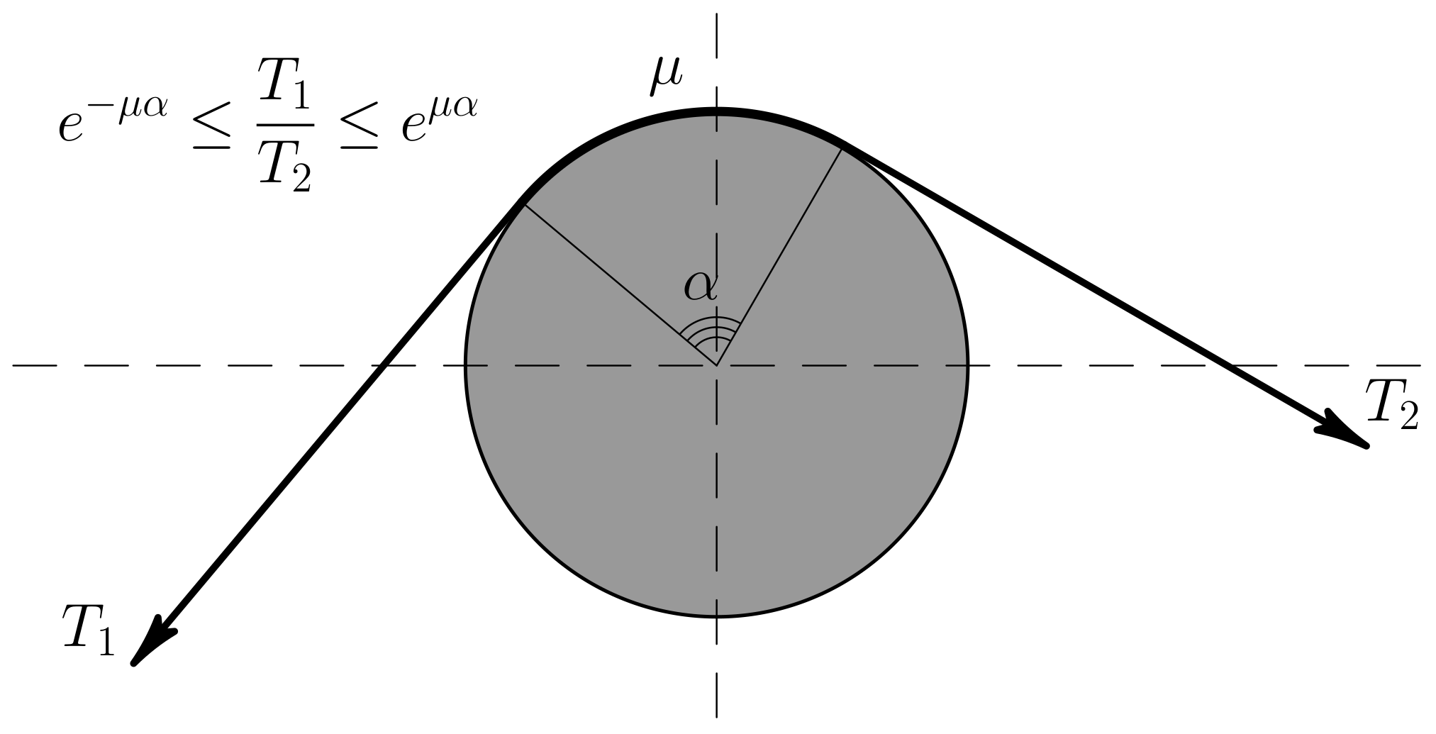
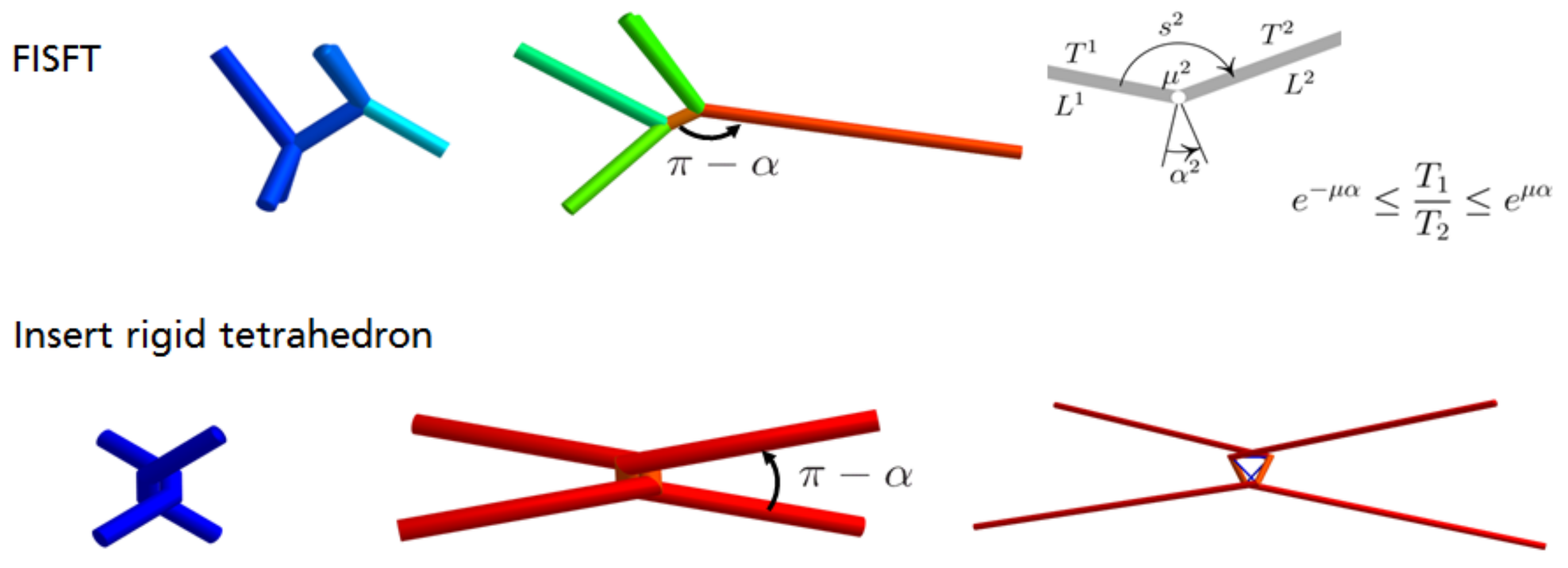
When the fiber is not straight, stick and slip conditions change their form. For the case of fiber in a contact with rigid cylindrical surface the friction stick or slip condition is given by the Euler-Eytelwein formula, also known as capstan equation or belt friction equation, see, e.g., [
18]. It is illustrated in
Figure 1. It has the following form:
where
defines the total angle, swept by the rope. We extrapolate this result for pairs of fibers in contact, where
is computed from angle between direction vectors of elements, adjacent to the contact node. The details will be provided further.
By the assumption on the geometry, the contact takes place only in nodes and never inside of elements. Any fiber is equilibrated iff (if and only if) for all pairs of the adjacent elements
and
of the fiber the friction stick condition from (
20) is fulfilled:
where
is the friction coefficient between the fibers in contact and
. Here,
is the angle between the direction vectors of
and
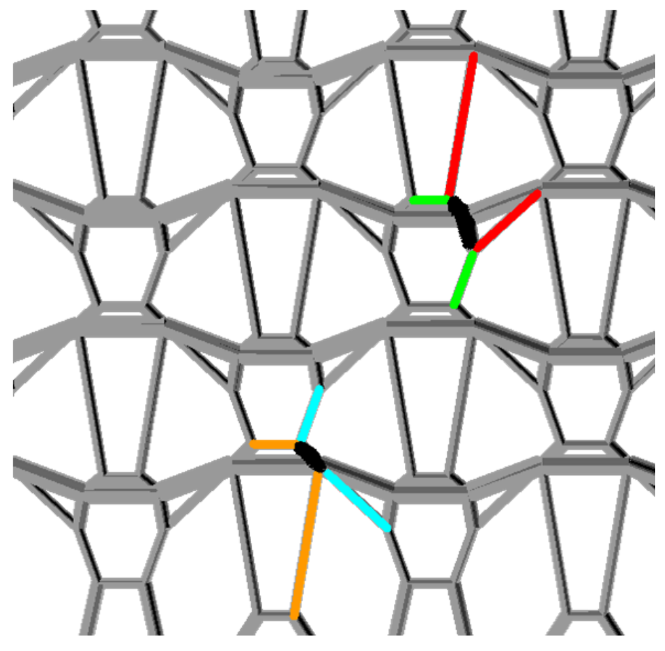
, starting from the contact point (see Figure 12 for an illustration in an example).
The slipping is modeled through redistribution of the material between the elements of the fiber, i.e., if the fiber is a sequence of elements
then their initial lengths
change to satisfy (
21). This condition can be reformulated as an optimization problem.
Consider two adjacent elements
and
. Let undeformed fiber length
flow from element
to element
. Then we observe that after this redistribution we have
where
denotes non-deformed length parameter after the redistribution. It is easy to see that the latter relation between
and
automatically ensures that the material conservation equation
holds.
Recall that the tension force in each element of the fiber is given by
. The function
is assumed to satisfy following natural conditions:
,
is strictly monotonic. Consider a function
where
means the positive part (zero, if the expression is negative).
J is always non-negative. One can easily observe that point
satisfying
is a minimizer of
J, and we have
, i. e. the minimum is attainable. However, this minimizer is in general not unique and not the desired one (one can observe that it corresponds to
).
If function
f is smooth,
. A problem
is thus suitable for numerical treatment by gradient methods.
The gradient of
J can be computed explicitly. Introduce notations
depends only on
,
and
. We have
for
. Cases
and
can be easily derived from the latter equation by omitting certain terms. The gradient of
J is constructed from gradients of
in obvious way, since
.
2.4.2. The Adhesive Friction Model
Consider two bodies in frictional contact with contact interface measure A and the total reaction force between the bodies N.
The adhesive term is a kind of Tresca friction, which is given by a known traction, a material characteristics, and should be multiplied by the contact measure. In our case, the contact area is one-dimensional manifold,
A and the distributed force or traction is in
. However, the adhesive experiments with yarns are for specific yarn thicknesses and results are measured in Newton. Thus, the adhesion coefficient
is chosen to be in Newton, with the adhesive force in a node being
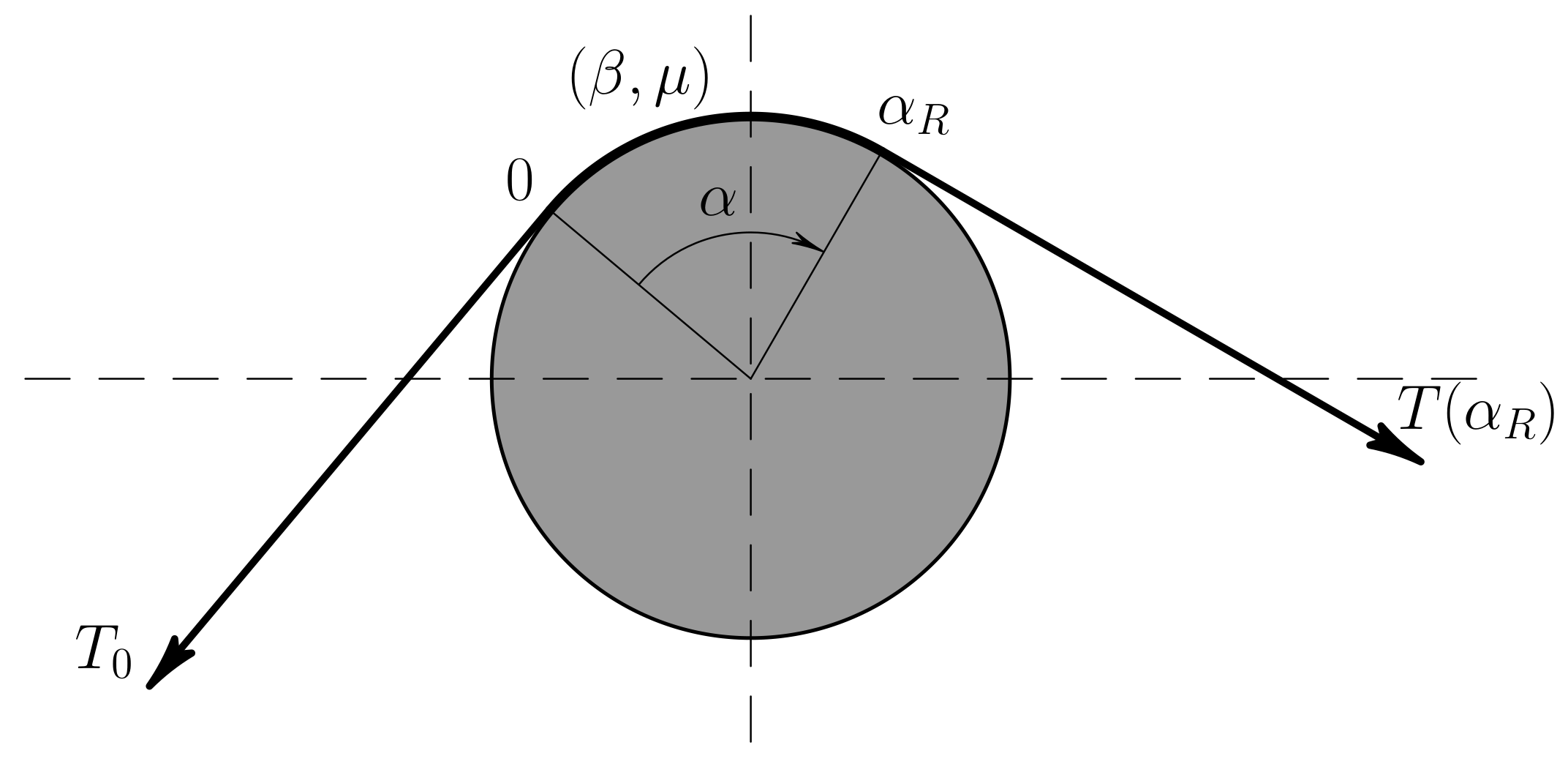
. Here, the angle
is defined shown in
Figure 2.
Consider the following friction law:
This is standard Coulomb friction law augmented with adhesive friction. Adhesion arises from interaction of yarns with each other after the relaxation due to interweaving of their filaments.
Consider a cylinder and a rope as shown in
Figure 2. Assume that:
tension force at the left end of the rope is known and equals ,
the system is in critical statical condition,
the friction force is such that the tension force is a monotonically increasing function of .
The problem is to determine the critical tension force at the right end of the rope, i. e. a value, such that for greater force values at the right end the sliding occurs and for lower values the system is in equilibrium.
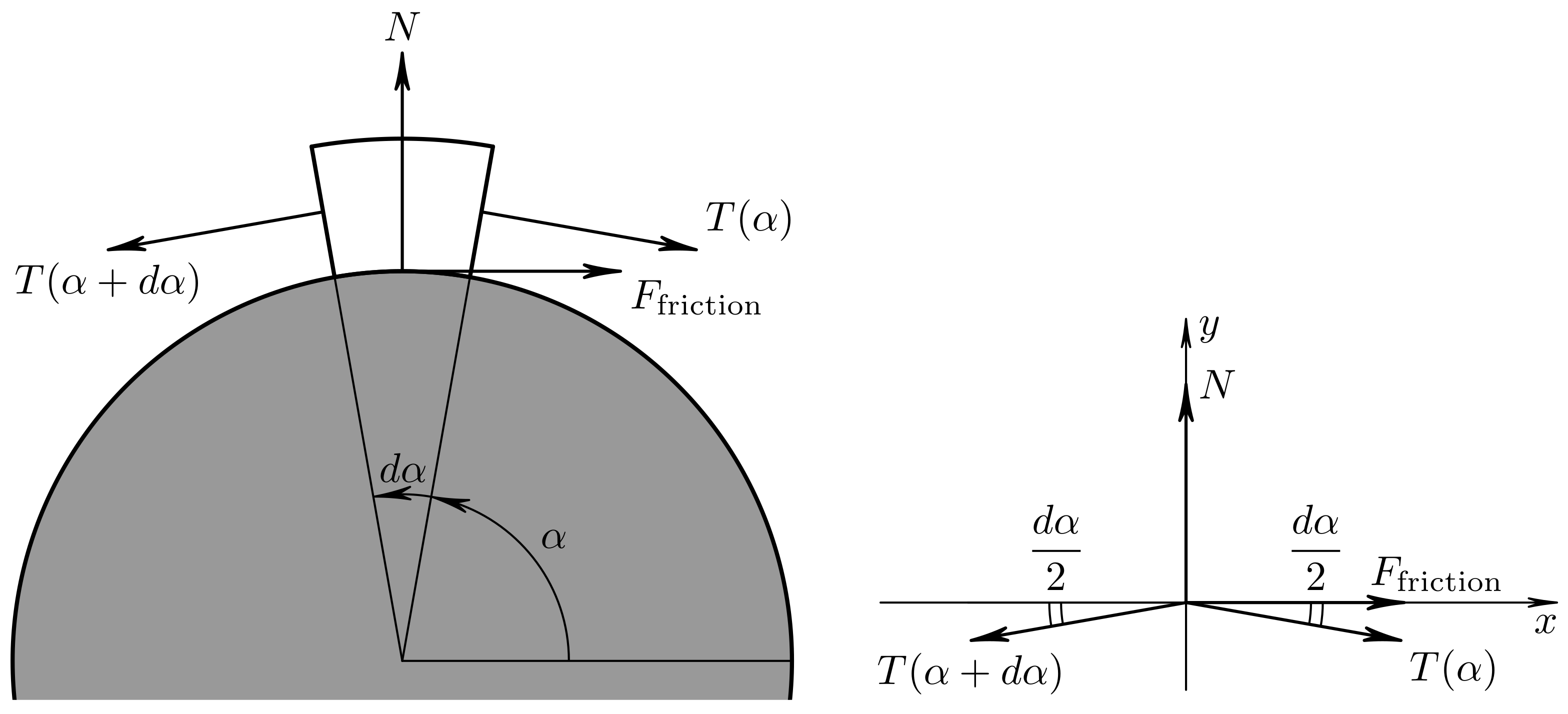
To do this consider equilibrium of a small element of the rope on the cylinder. Let the tension force
T be a function of
. The total force acting on the element is depicted in
Figure 3. Projecting on the axes
x and
y we obtain the differentials
substituting
from (
30) for the critical case yields
Substitute
N from the second equation into the first and divide both sides over
:
Passage to the limit
yields the Cauchy problem for the tensional force in the rope:
Further, consider a cylinder and a rope with tension force values given at both ends and
as shown in
Figure 2. The problem is to determine whether the system is in equilibrium (stick) or the rope slides on the cylinder (slip). We approach this problem in the following way:
compute and ,
solve the problem (
34) with
and compute
,
the state of the system (stick/slip) is determined from comparison of and .
This approach yields the following rule:
The conditions are checked in the numerical scheme. If they are not fulfilled, the sliding process takes place and the rope slides in the direction of greater force.
2.4.3. General Case
A more general case of (
30) can be considered:
where
G is certain non-negative function. It can be parametrized by additional parameters, for example in (
30) we had
For a cylinder and a rope we make the same assumptions as before and arrive to the Cauchy problem for the tensional force in the rope:
where
,
for
. Under these assumptions, problem (
39) has a unique monotonically increasing solution and can be solved numerically.
Further, consider a cylinder and a rope with tension force values given at both ends and
as shown in
Figure 2 but now with (
30). Then to determine whether the system is in equilibrium:
compute and ,
solve the problem (
39) with
and compute
,
the state of the system (stick/slip) is determined from comparison of and .
2.4.4. The decaying adhesion friction model
This model is defined by
where the decay parameter
and
are the material parameters:
can be seen as a lower bound for the Tresca friction (when adhesion disappears) and
as an upper bound for Tresca adhesive friction.
If , then the model reduces to the adhesive model described above.
The following Cauchy problem is obtained for a cylinder and a rope:
The right-hand side is of Caratheodory type and positive if , , and are positive. The whole problem is thus well-posed.
Observe first that if
, then (
41) is equivalent to (
34). Assume that
. The solution of (
41) is given by
Finally, the state of the system with given angle
and forces at the ends
and
is defined from the following rule:
2.5. Finite Element Formulation
Summing up (
10) over all elements will result to system of equations for nodal displacements (and in coupled case also for material redistribution parameters)
where
denotes the set of elements incoming in node
n,
is force vector of element
e,
is prescribed force in node
n, and
is the set of all free nodes, i.e., nodes, where no constraints for coordinates are prescribed. For some nodes
Dirichlet values are given, the displacements of these nodes are thus given:
Let
denote nodes where at least two fibers touch each other (i.e., those nodes where pairs of elements, which can exchange the material directly, touch). Further, let
,
,
be friction parameter, adhesion parameters and angle at such a node.
and
are refined as in (
15).
The friction condition leads to inequality constraints for material redistribution parameters:
2.6. Numerical Algorithm
The problem (
46)–(
48) inherits all properties of the same problem without friction. One can face strong non-linearities, high condition numbers (how much the output value of the function can change for a small change in the input argument), instabilities of the structure itself, and snap-throughs. Even more, when an element
e is relaxed, then its tangential stiffness matrix is degenerate. This is explained by the behavior of the energy (
5) at point
: for nodal displacement vectors, perpendicular to element’s current axis, the functional behaves the same way as function
at point
. Taylor expansion of this function up to the fourth order term is zero, delivering problems to numerical methods of optimization or non-linear equations solution, which use at most second-order information. Either higher order methods or regularization is thus required together with robust Newton-Raphson or Gradient method to solve (
46)–(
48), where friction constraints complicate the matters even further.
2.6.1. Continuation Method
We apply the standard Continuation technique [
19,
20,
21] to deal with the issues mentioned. Consider a family of parametrized problems
,
, defined as
Equation (54) has to be replaced by (49) or (50) for the two adhesion cases.
The problem corresponds to the structure without any outer forces, while is equivalent to (46)–(48), the equations with applied outer forces and boundary nodal displacements (Dirichlet values) that have to be solved. We assume that for some values and the solution to is known. Then we approach to the solution of , consequently solving for , where and points and are close in some sense (K is the number of necessary iterations). The benefit of such method is that to numerically solve problem one can use the solution of as the initial guess, thus ensuring the convergence of each single step and then the whole algorithm.
If at some step i numerical methods fail, we try to reduce the step size. We achieve this by introduction of additional step between i and .
2.6.2. Step of Continuation Method
Assume that the solution of the problem is available. Show how one computes . For the sake of simplicity we consider decoupled case here, i.e., when problems (51)–(53) and (54) are solved separately.
Set initial guess to .
Update Dirichlet displacements and Volume Force values.
Solve decoupled displacements-flow problem:
- (a)
If error norm is acceptable, go to 4.
- (b)
Obtain nodal displacements from (51)–(53) with material flow variables fixed. It can be solved numerically as a system of non-linear equations.
- (c)
Obtain flow variables from (54) with nodal displacements fixed. It can be solved numerically as an optimization problem.
- (d)
After solution of (54) the error norm of (51)–(53) can increase. If it violates predefined criteria of the error to be small, go to 3b.
At this point the problem is solved. Proceed to the next step.
4. Discussion
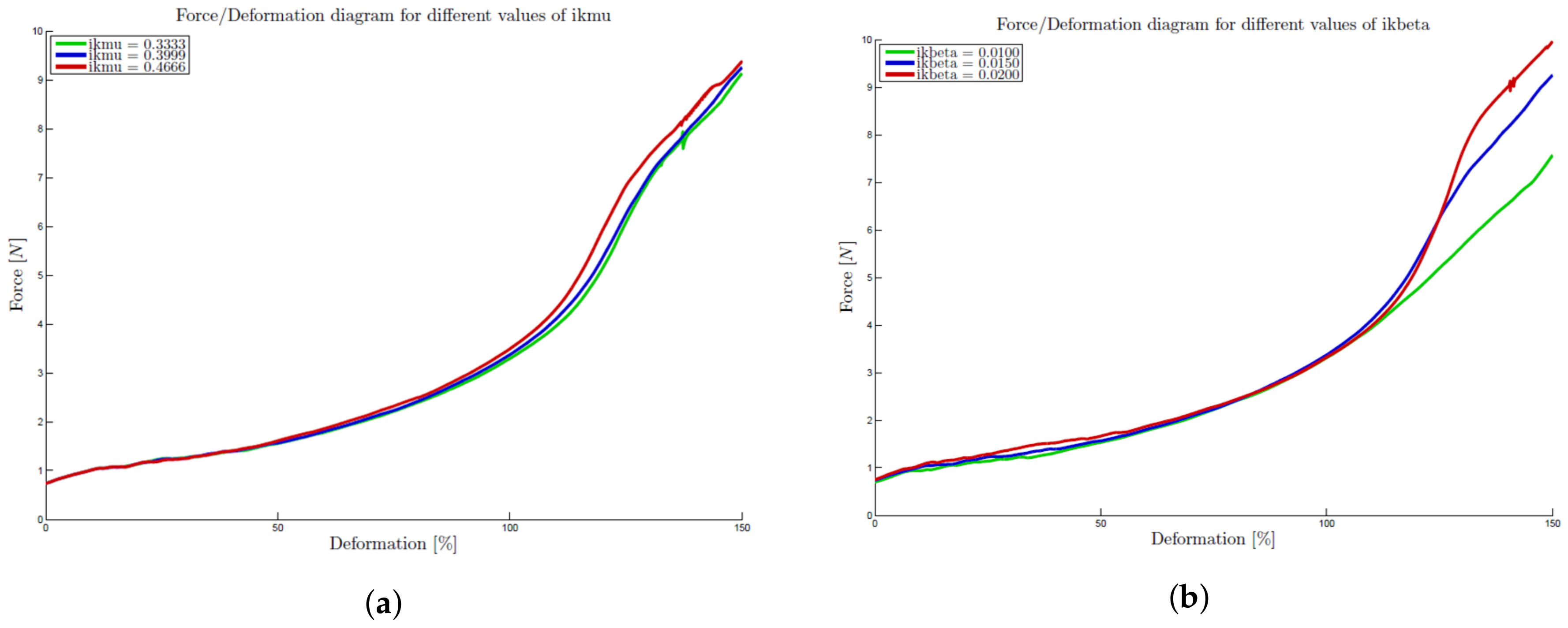
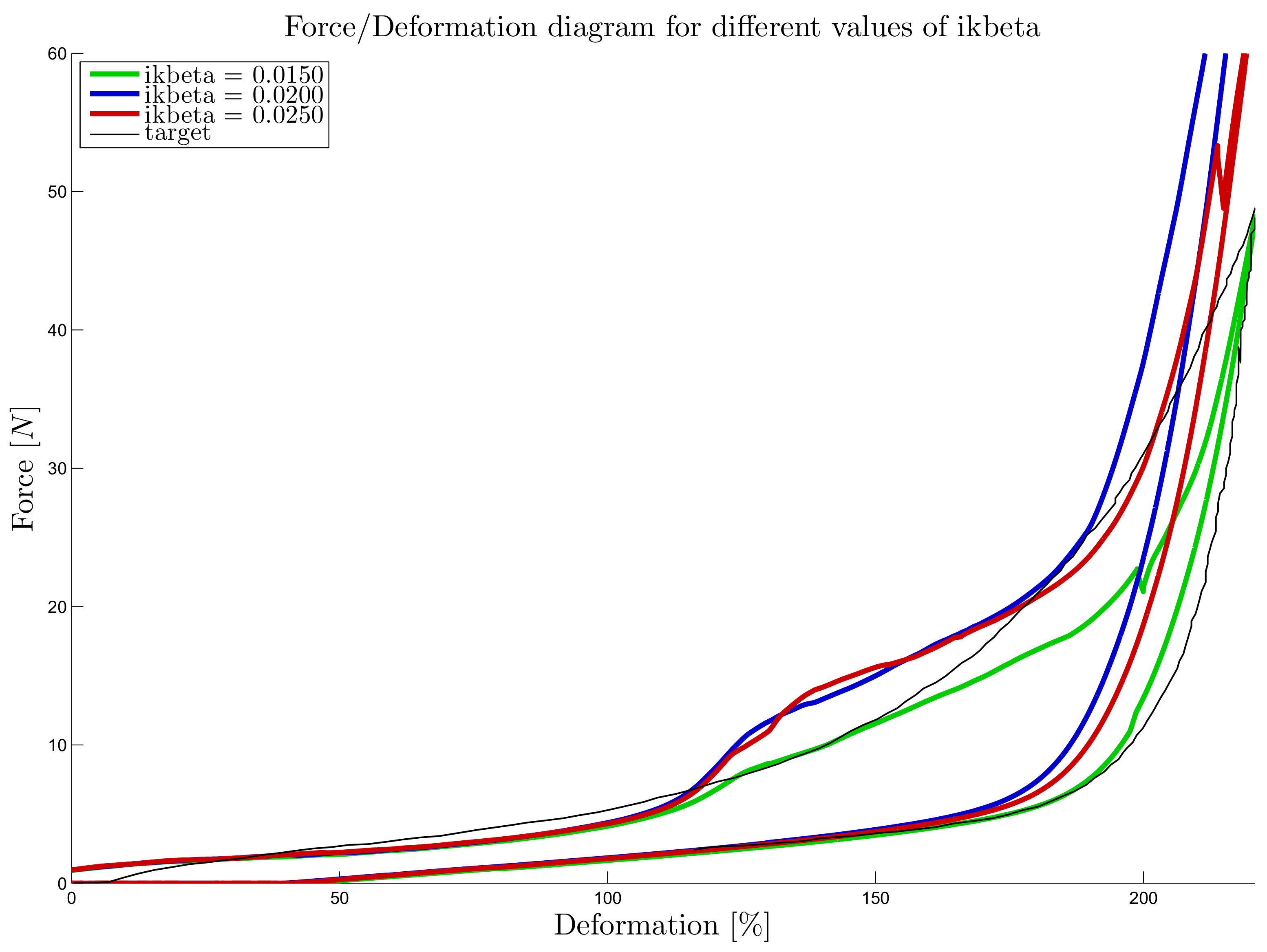
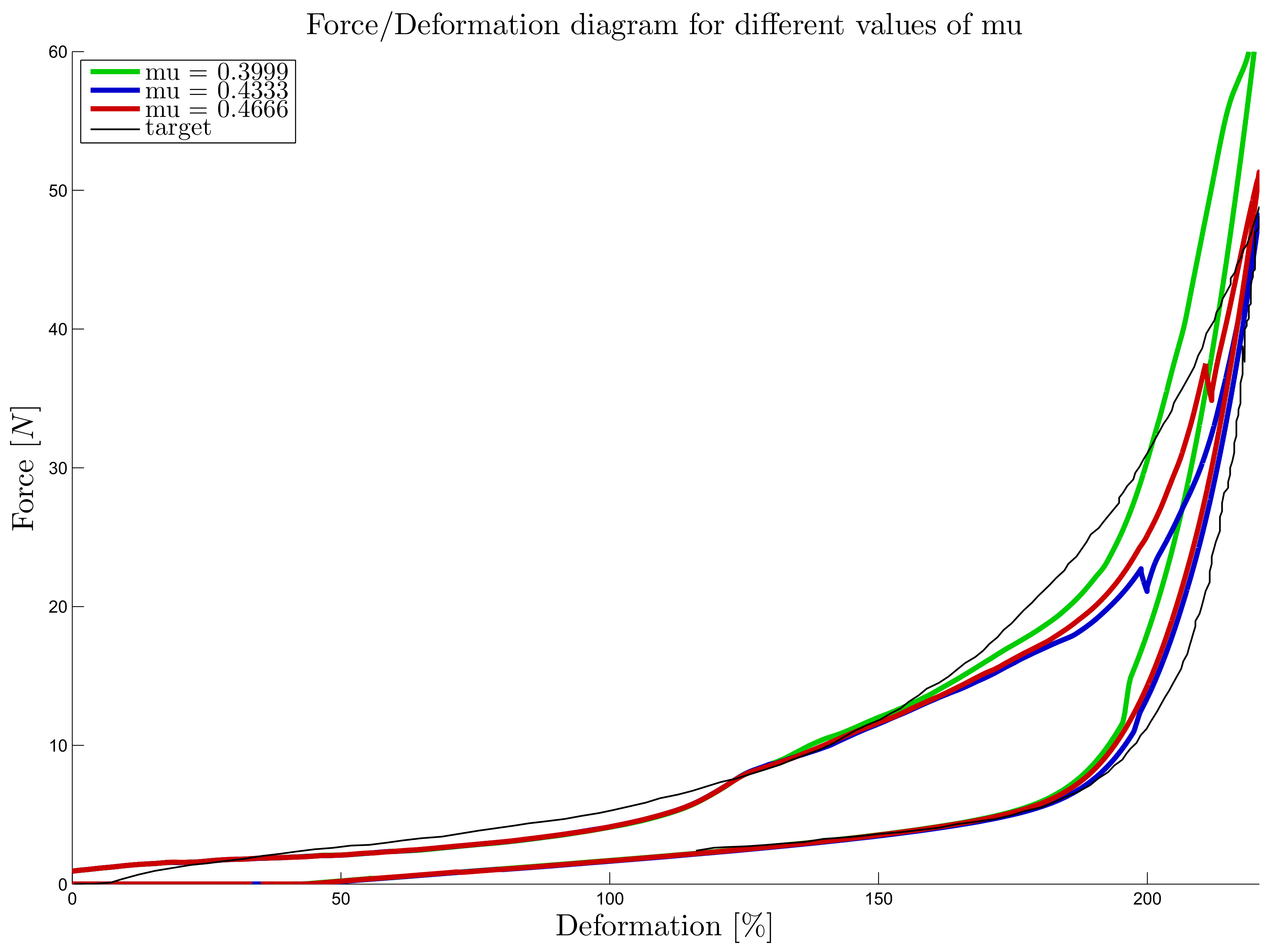
An important issue is that the developed model is appropriated for large stretch deformations, when the size of contact knots becomes very thin compared to the distance between them and they can be considered as point-contacts. The results indicate that the reduced cross-section of the yarns due to the transverse deformation can be captured by the decaying adhesive force.
In the case of thick yarns and dense structure, the model should either be replaced by a two-scale model, resolving the contact knots in all 3-dimensional details, as in works of S. Lomov, or extended to the bending of yarns at the contact points, as in works of Damien Durville [
4,
22,
23,
24,
25] and a simplification in a form of a changing gap-factor can be introduced, imitating the yarn thickness reduction on the contact nodes during the stretching, as in the last example.
The last remark is that the presented model is suitable for multifilaments rather than for monofils, since it ignores bending and shear stresses and deformations in yarns and is appropriated for yarns working mostly on tension and providing a very lower shear and bending resistance. The approach is based on the computation in terms of forces and not in terms of stresses, which avoids some cross-sectional effects.
