Article

Deformation Behavior and Experiments on a Light Alloy Seamless Tube via a Tandem Skew Rolling Process

1
Department of Mechanical and Electronic, Yuncheng University, Yuncheng 044000, China
2
The Coordinative Innovation Center of Taiyuan Heavy Machinery Equipment, Taiyuan University of Science and Technology, Taiyuan 030024, China
*
Author to whom correspondence should be addressed.
Metals 2020, 10(1), 59; https://doi.org/10.3390/met10010059
Submission received: 29 November 2019 / Revised: 24 December 2019 / Accepted: 25 December 2019 / Published: 29 December 2019
(This article belongs to the Special Issue Forming Processes of Modern Metallic Materials)

Abstract

:
As a process for producing seamless tubes, the tandem skew rolling (TSR) process was proposed. In order to study deformation characteristics and mechanism on tubes obtained by the TSR process, a numerical simulation of the process was analyzed using Deform-3D software. Simulation results demonstrated the distribution of stress, strain, velocity, and temperature of a seamless tube in the stable stage during the TSR process. Actual experiments of carbon steel 1045, high strength steel 42CrMo, and magnesium alloy AZ31 were carried out in a TSR testing mill. The results demonstrated that the TSR process is qualified for producing tubes of high quality, with an accuracy of ±0.2 mm in wall thickness and ±0.35 mm in diameter. This process is suitable for manufacturing seamless tubes that are difficult to deform or that have been deformed in a narrow range of temperature.

1. Introduction

The steel industry is now in a post-industrial era of steel, whose theme is “green manufacture, make green.” The short process is one way to meet the requirement for industrial development. The tandem skew rolling (TSR) process is an ingenious metal-formed technique for producing seamless steel tubes that can achieve continuous skew rolling by combining the piercing section with the rolling section [1,2]. Compared with the conventional process of manufacturing seamless steel tubes, a three-step forming process of piercing, rolling, and reducing, the TSR process is a shorter, two-step forming process.
The TSR process has been investigated for many years. In order to implement the TSR process, a TSR testing mill was designed and developed for experimental research. The mechanical structures of the mill and a method of adjusting process parameters were introduced and described [3,4]. A theoretic model of the TSR process was then established and derived in terms of dual stream functions, which could obtain the kinematically admissible velocity field of the billet during the rolling process [5]. Based on the times spent on the deformation process of the two sections, the velocity coordination of the rollers in both sections was researched, and a proper velocity match was obtained [6]. Moreover, to study the interstand tension in the tandem process, a tension testing device was developed and used with the testing mill, which reflected the changes in the stress of billet [7]. Further, how the process parameters affected the rolling force and the dimensional precision of the tubes was investigated [8]. Finally, aiming to improve the dynamic performance of the control system in the TSR process, a dynamic matrix control algorithm together with a particle swarm optimization algorithm was used to optimize the parameters in the process [9,10].
Due to the application of a finite element model (FEM), it was possible and economical to precisely analyze the changes in the shape of workpieces during metal deformation. Wang et al. [11] used the finite element method to analyze the three-roll skew piercing process. Bogatov et al. [12] studied the rotary piercing process using Deform-3D software and obtained the trajectories of points with different radial coordinates. Pater et al. [13] studied skew rolling with three tapered rolls for producing long main shafts of steel using the commercial FEM simulation software suite Simufact Forming v.12. They also studied the tube forming process in Diescher’s mill [14], and the thermo-mechanical piercing process using the commercial software MSC SuperForm 2005 [15]. Stefanik et al. [16] studied the three-high skew process for producing aluminum bars using the Forge 2011® software. Romantsev et al. [17] studied the piercing process for a new four-high screw rolling mill without guides, which was designed by comparing existing piercing processes in screw rolling mills. Toporov et al. [18] used finite element modeling to improve the piercing operation on a piercing mill. Murillo-Marrodán et al. investigated the friction conditions between the rolls and the workpiece of a hot skew roll piercing process with three friction laws via the FORGE software [19].
Aiming at the precise representation of the deformation characteristics of billets during the TSR process, numerical simulation of the TSR process using the software Deform-3D was employed to study the distributions of stress and strain. Based on numerical analysis, experiments were carried out with carbon steel 1045, high-strength steel (HSS) 42CrMo, and magnesium alloy AZ31 on the TSR testing mill to verify the feasibility of the process. The TSR process was originally developed to manufacture seamless tubes that were difficult to deform (e.g., high strength steel 42CrMo) or could only be deformed with a narrow temperature range (e.g., AZ31 alloy) because the temperature drop was slower in this process.

2. Materials and Methods

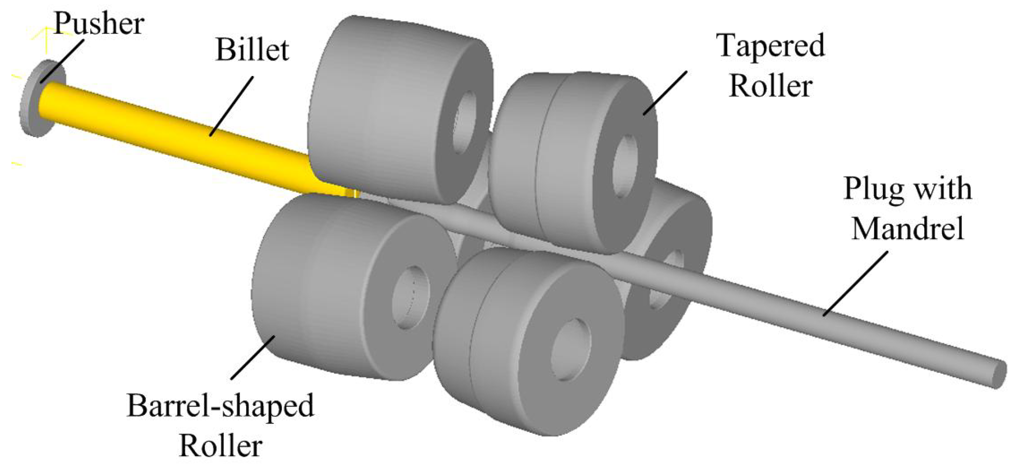
By the TSR process of producing seamless tubes, the heated cylindrical billet was pierced and rolled continuously in the mill, in which the piercing and rolling processes were completed at once. The schema of the TSR process is presented in Figure 1. The process involves three Mannesmann barrel-shaped rollers in the piercing section, three Assel tapered rollers in the rolling section, and a plug together with a mandrel and a billet.

2.1. Experimental Test

Through untiring efforts made over many years, the TSR testing mill was developed for experimental studies of seamless tubes, as shown in Figure 2. This mill consists of the driving part of the piercing section, the main mill (the piercing section combined with the rolling section), the mandrel carriage in which the plug is joined with the mandrel by a screw thread, and the driving part of the rolling section.
In order to extend the range of the TSR process, in the experimental study, the cylindrical billets of carbon steel 1045, HSS 42CrMo, and magnesium alloy AZ31 were used with dimensions φ40 × 500 mm. The rollers in the piercing section were the same sizes with a maximum diameter of 180 mm and a length of 140 mm, while the rollers in the rolling section were the same sizes with a diameter of 180 mm at the shoulder and a length of 120 mm. The plug was used together with the mandrel with a diameter of 30 mm. The rollers in the piercing section, driven by A.C. motors, rotated in the same direction with the same invariable rotary speed of 169 rpm. The rollers in the rolling section, driven by D.C. motors, rotated in the same direction with the same variable rotary speed, which should match the speed of the rollers in the piercing section under different process parameters. The reasonable ranges of process parameters were obtained through previous multiple experiments. The rolling temperature was very important for hot plastic deformation, especially the alloy material. Therefore, the initial rolling temperatures for steel 1045, HSS 42CrMo, and AZ31 alloy were set at 1200, 1250, and 400 °C, respectively, which were selected to make full use of their plastic deformation capacity under corresponding high temperatures. The process parameters used in experiments are shown in Table 1.

2.2. Finite Element Model

For the analysis of the metal flow and deformation in the TSR process, the commercial software Deform-3D was applied. Due to the complexity, the analysis of the metal flow and deformation should be simulated only in a 3D state of strain conditions. In Figure 3, the worked-out FEM of the TSR process according to the schema in Figure 1 is presented. This model consists of three barrel-shaped rollers, three tapered rollers, a pusher, a plug together with a mandrel, and a billet. The billet is defined as a plastic body, and the others are modeled as rigid bodies. Additionally, the pusher was used to place the billet into the area between rollers. The process parameters (e.g., feed angle, entrance face angle, roll gap, and speed) used in the FEM were the same as those used in the experiment and are shown in Table 1. However, a short distance of 200 mm between the piercing section and the rolling section was used in the simulation in order to save computation time, which was 630 mm in the TSR testing mill.
Aiming to reflect the metal flow and deformation rule, only the 1045 steel was selected in simulation. A rigid plastic material model, which is the 1045 steel of the software’s own model, was employed and assigned to the billet with dimensions φ40 × 200 mm, whose flow curves are shown in Figure 4. The billet was meshed and approximately divided into 30,000 tetrahedral elements. It was assumed that the billet was heated to 1200 °C, and the temperatures of the rigid tools, the rollers, and the pusher were constant at 150 °C during the whole forming process. In the case of the plug and the mandrel, it was assumed that the temperature was the same as the environment temperature—20 °C. It has been stated that the coefficient of the heat exchange between the tools and formed material is 11 N/(s·mm·C). However, the value of this coefficient determining the heat exchange between the billet and the environment was 0.02 N/(s·mm·C). Friction is an important factor for a smooth rolling process. The greater the friction, the easier it is to roll smoothly, and the less time spent in simulation. Due to the purposeful roughness of the rollers, it was assumed that the friction factor for these rollers had a limiting value of 1.0. However, because the plug was made with a follow-up rotational movement with the billet during piercing, the friction of the surface of contact between the plug and the billet was very low. Therefore, the friction was set to 0.3 in the FEM.

3. Results and Discussion

3.1. Numerical Modeling Results of the Steel 1045 during the TSR Process

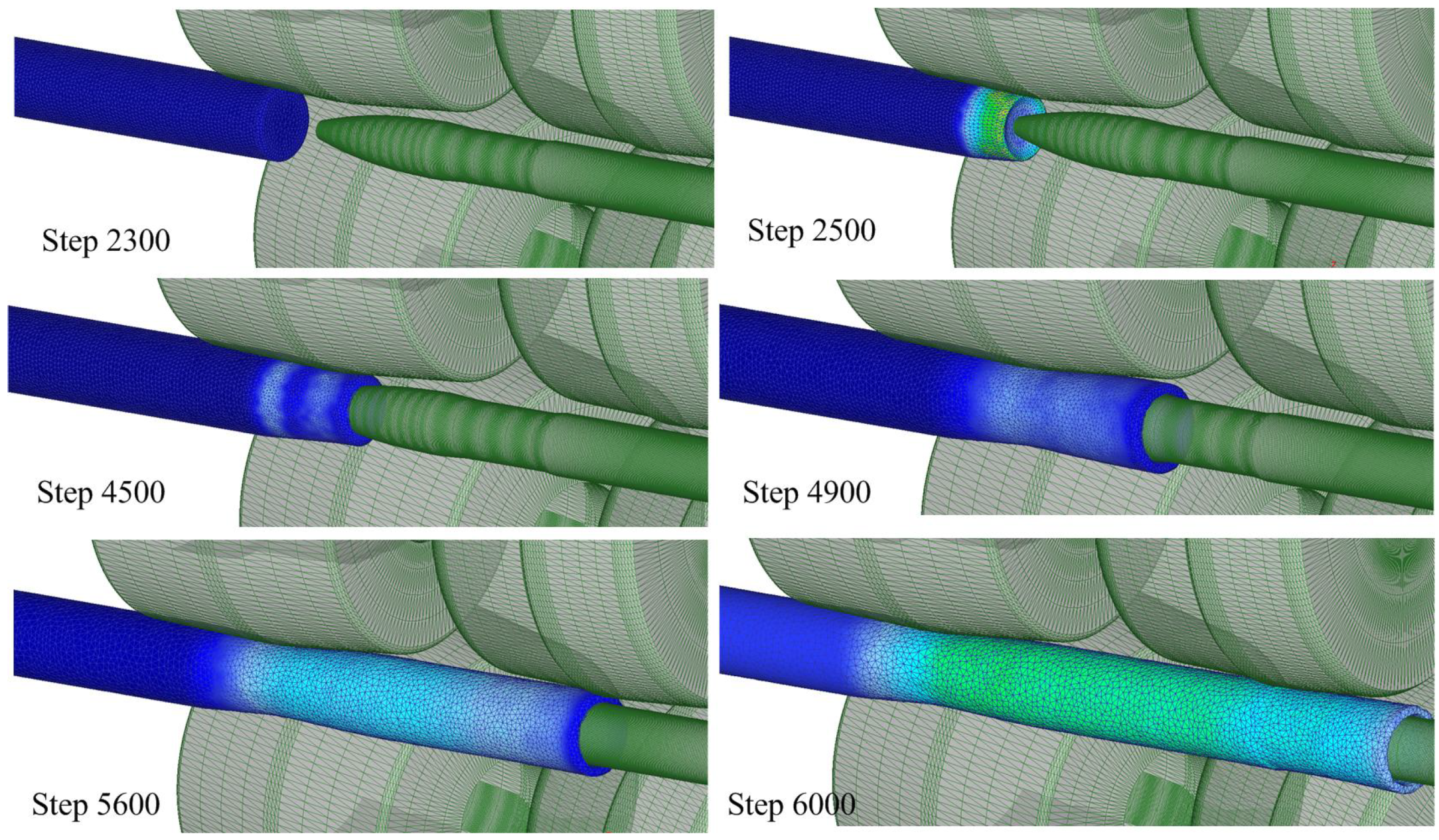
The changes in the billet shape during the TSR process are presented in Figure 5, from which two rollers are omitted to improve readability.
Based on Figure 5, at the beginning, the billet is clamped by rollers in the piercing section, which puts it into a rotary motion and later transmits it in the axial direction. A process of rotational compression is then started, and this lasts until the head of the billet has made contact with the plug. Next, the forming process of the hollow shell internal hole begins, and its size is determined by the applied plug dimension. At approximately Step 4900, the head of the hollow shell moves straight out from the rollers in the piercing section. Further, with continuous rolling, the pierced hollow shell makes contact with the rollers in the rolling section at approximately Step 5600 and is rolled into the roll gap. Under the combination of the roller in the piercing section and the rolling section, the TSR process reaches a stable phase after Step 6000.
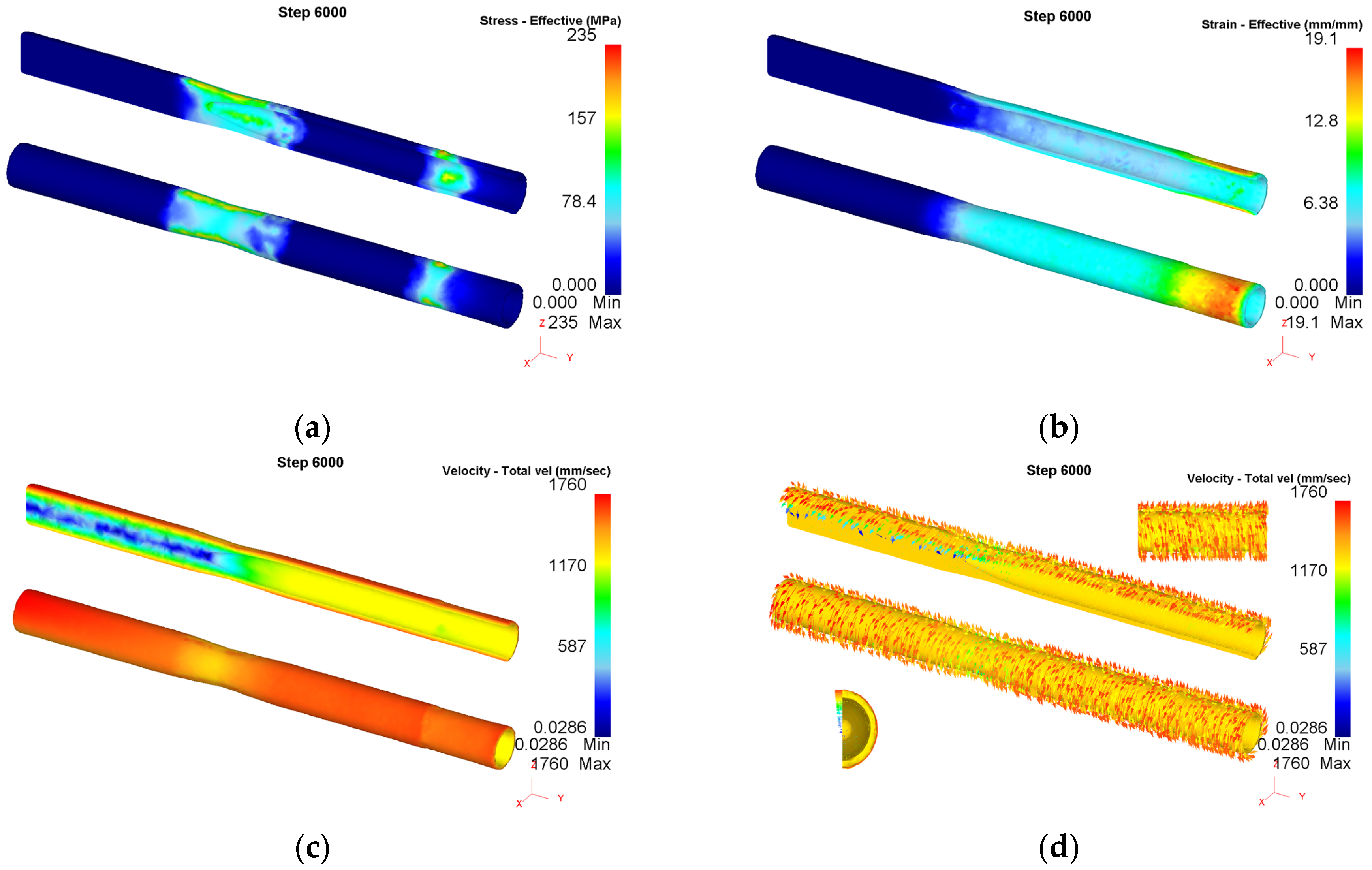
The distribution of stress determined for the stable stage in the longitudinal and cross-section planes is presented in Figure 6, and the strain is presented in Figure 7. The data in Figure 6 shows that higher stress intensity magnitudes occur at locations outside where the surface contacts the rollers and are equal to approximately 160 MPa in both sections, and the highest values are concentrated at the shoulder of the rollers in the rolling section. Meanwhile, the changes in the different cross sections indicate that it makes the sharpest contact only at the moment when the rollers bite the billet from three directions. As the billet moves along the deformation region, the magnitude of the stress intensity, while it deepens from outside to inside, increases with an increase in the contact surface. The same change regularity is presented in the rolling section.
In Figure 7, it can be observed that strains are presented in a laminar way. However, the greatest strains are present in the external layers of the formed tube. In Figure 7, the changes in the billet cross profile along the whole length of the forming area can be analyzed. Due to the influence of the rollers, the cross profile varies from a circle to a triangular circle and then to another circle in the piercing section. The cross profile continuously varies from a circle to a triangular circle and then to another circle in the rolling section. Finally, after the metal moves through the mandrel, the tube gains the required circular shape.
To clearly display the distributions of stress and strain determined for the stable stage, Figure 8 shows an isometric view and longitudinal section of distribution patterns for the seamless steel tubes during the TSR process as follows: (a) stress, (b) effective strain, (c) velocity, and (d) velocity with a vector plot, in which the distributions of the velocity field and metal flow are obtained.
In Figure 8c, distribution law is arranged in layers of the velocity fields, which show a decreasing trend from outside to inside. The highest magnitude appears at the outside surface, while the lowest magnitude appears at the central axial zone in front of the plug. When the head of the billet touches the plug, the core metal flows outward along the surface of the plug under the friction force given by the rollers. This force was enough to present the metal flow rule of the tube obtained by TSR process. Figure 8d gives the velocity vector of the tube produced in the process and shows the metal flow rule. The velocity vector is always tangential to the surface and forms an angle with the axial line, which determines the movement pattern of the billet. When touching the plug, the core metal flows outward along the surface of the plug. Note that no cavity is formed in the core metal in front of the plug.

3.2. Experimental Analysis

3.2.1. Quality of Tubes

Figure 9 shows the seamless tubes produced on the TSR testing mill. As shown in Figure 9, the tubes of carbon steel 1045 and AZ31 alloy achieved the desired cylindrical shapes. However, HSS 42CrMo could not be successfully completed with the rear-jamming of the tail of the billet present in the piercing section. The season was due to the collapsing nose of the plug, which resulted in the increase in axial resistance. Meanwhile, there were no significant defects on the outside surfaces of the tubes, except from the tail burrs of the AZ31 alloy and the trumpet-shaped heads of the tubes. In addition, the carbon steel 1045 tubes had diameters of 39.14 ± 0.35 mm, wall thicknesses of 4.67 ± 0.2 mm, and lengths of up to approximately 1360 mm, and the dimensions of the AZ31 alloy tubes were 39.85 ± 0.35 mm, 4.42 ± 0.25 mm, and 1200 mm, respectively. However, only a length of 750 mm of HSS 42CrMo tube was obtained and rolled by the TSR process, and the diameters and wall thicknesses were about 38.22 ± 0.35 mm and 4.33 ± 0.3 mm, respectively. The comparative data of these tubes are listed in Table 2.
The distribution of thicknesses of the tubes along the axial direction is shown in Figure 10. Figure 10 shows that the tubes of carbon steel 1045 and the AZ31 alloy had a more accurate thickness compared with the HSS 42CrMo tube produced in the TSR testing mill. Meanwhile, under the same process parameters in the experiment, different diameters and thicknesses were obtained with different materials and properties. The extension coefficient of the carbon steel 1045 was about 2.72, while those of HSS 42CrMo and the AZ31 alloy were about 2.8 and 2.4, respectively. The reasons for this might be linked directly to the plastic deformation properties themselves. From the condition of experiments, the color of the tandem rolled tube of the HSS 42CrMo darkened more quickly than that of the carbon steel 1045, which was sufficient to prove that HSS 42CrMo was a temperature-responsive metal. Under a proper rolling temperature, the AZ31 alloy tube was rolled more easily than others. Additionally, a uniform wall thickness of the middle section of the tubes was obtained, the reason for which might be the stable rolling in the process.

3.2.2. Roll Force

Figure 11 shows the experimental data related to the roll force of the two sections and the plug axial force in the TSR process for the production of seamless tubes: (a) carbon steel 1045, (b) magnesium alloy AZ31, and (c) HSS 42CrMo, respectively. Because of the plug combined with the mandrel, the date of the axial force could be the sum of the dates on both. As shown in Figure 11a, the whole process of the rolling carbon steel 1045 can be easily divided into three stages: (i) piercing, (ii) piercing and rolling, and (iii) rolling, which is the same as the AZ31 alloy. However, there was no stage of rolling solely in Figure 11c because of the rear-jamming present during the rolling tube of HSS 42CrMo. What could be seen in Figure 11 is that the roll force values of both sections of the rolling HSS 42CrMo are greater than those of the rolling carbon steel 1045 and the AZ31 alloy, respectively. The roll force of the AZ31 alloy is the smallest. As is known, compared with carbon steel, HSS has a higher tensile strength when small amounts of alloying elements are added, while magnesium alloy has a lower one.
As shown in Figure 11a,b, with the billet pushed and contacted with the rollers of the piercing section, the roll force of the piercing section increased steeply in stage (i). In quick succession, when the head of the incoming billet made contact with and passed through the plug, the roll force of the piercing section slightly rose and then reached a relative steady state, followed by a slight decline. Meanwhile, the axial force on the plug also increased and then remained stable.
Continuously, when the pierced hollow tube moved forward in a spiral fashion and fed into the roll gap of the rolling section, it was situated in the real TSR process in stage (ii). The roll force of the rolling section increased rapidly and afterwards decreased slowly to a certain extent. Meanwhile, the force of the two sections featured a downward sloping curve on a small scale, because of the interstand tension between the two sections. The axial force also increased with the addition of force on the mandrel.
In stage (iii), as the billet exited the roll gap of the piercing section, the force of the piercing section decreased steeply, and the axial force decreased rapidly to a small value because of the lack of axial force on the plug. Meanwhile, the force of the rolling section slightly increased due to the lack of the interstand tension mentioned above. The force decreased to 0 when completed.
As shown in Figure 11c, the rolling HSS 42CrMo took longer than the carbon steel 1045, which reflects the difficulty of rolling high-deforming steel, such as 42CrMo. Based on Figure 11c, the slip between the roller and the billet in the piercing section occurred at about 12 s, accompanied by the increase in the force of the piercing section, and no axial movement occurred thereafter in the actual experiment. The force decreased to 0 after a manual stop. The reason for this is mentioned above: the collapsing nose of the plug and the increase of axial resistance must be a major factor causing the rear-jamming, which increased the force of axial resistance, even with greater friction. As is known, friction between the billet and the roller is key in the rolling process. Meanwhile, the material characteristics of HSS 42CrMo in the deformation may be an intrinsic factor, which is determined by the small amounts of alloying elements. Even so, this is enough to prove the feasibility of the TSR process for HSS seamless tubes. The rolling process thus might become smoother in two ways: the rolling velocity might increase, and the roll friction might increase. These methods, under these conditions, could therefore decrease the work time of plugs.
As shown in Figure 11b, the variation tendency of the roll force of the AZ31 alloy was similar to the one of steel 1045. Only the used time of each deformation section was shorter than steel 1045, and the average force values were lower. Based on other research on piercing experiments with the AZ31 alloy [20,21], using the TSR process to manufacture seamless tubes of AZ31 alloys was a daring attempt and has been proven to be a breakthrough.
Generally, this could be used as a reference for similar kinds of material. Conversely, there might be some distinctions for different kinds of materials, in which some factors affect the results, e.g., deformation temperature, deformation rate, and deformation degree.
Fortunately, different material productions for tubes formed by TSR have been successful, and the process has been shown to be feasible for use. Further tests where the plug is replaced should be done, with the goal of achieving a longer contact time under high temperatures. Adjusting process parameters is another effective way of increasing the rolling velocity or shortening the contact time between the plug and the billet. The emphasis should be on high-quality tubes of nonferrous and high-deforming metals, such as tubes of titanium alloy used in oil well fields, and such high quality is the ultimate goal of the TSR process.

4. Conclusions

Based on the studies carried out, it was found that rolling on a TSR testing mill allowed TSR to be run with high efficiency in the deformation of seamless tubes pierced and rolled at the same time time, which makes continuous skew rolling more economical and practical. The following conclusions can be drawn.
(1)
The distribution of stress presented higher stress intensity magnitudes on outside surfaces contacting with the rollers.
(2)
The distribution of strain was presented in a laminar way, with higher strain intensity magnitudes occurring at the external layers of the formed tube. The cross profile varied from a circle to a triangular circle and then to another circle in the piercing section, and again, continuously, in the rolling section.
(3)
The distribution of velocity was also arranged in layers with a higher magnitude at the outside surface and the lowest one at the central axial zone in front of the plug.
(4)
Based on experiments in a TSR testing mill, the desired seamless tubes of carbon steel 1045, HSS 42CrMo, and the AZ31 alloy were obtained, with an accuracy of ± 0.2 mm in wall thickness and a diameter of ±0.35 mm.
(5)
The TSR process is suitable for manufacturing seamless tubes that are difficult to deform or that are deformed in a narrow temperature range.

Author Contributions

Y.S. and F.W. conceived and designed the experiments; F.M., J.H., and J.C. performed the experiments; F.M. and J.H. analyzed the data; F.M. performed the finite element simulations and wrote the manuscript. All authors have read and agreed to the published version of the manuscript.

Funding

This research was funded by the Scientific and Technological Innovation Programs of Higher Education Institutions in Shanxi grant number [2019L0852], the Major Project of the Ministry of Science and Technology of Shanxi Province in China grant number [20191102009], and the Start-Up Foundation for Doctors of Yuncheng University grant number [YQ–2019006]. And the APC was funded by [YQ–2019006].

Acknowledgments

The authors acknowledge the Funds for the Scientific and Technological Innovation Programs of Higher Education Institutions in Shanxi (No. 2019L0852), the Major Project of the Ministry of Science and Technology of Shanxi Province, China (No. 20191102009), and the Start-Up Foundation for Doctors of Yuncheng University (No.YQ–2019006).

Conflicts of Interest

The authors declare that there is no conflict of interest.

References

  1. Wang, F.J.; Shuang, Y.H.; Zhang, G.Q. A new type of seamless steel pipe production process-tandem skew rolling process. Steel Pipe 2014, 43, 54–58. [Google Scholar]
  2. Wang, F.-J.; Shuang, Y.-H.; Hu, J.-H.; Wang, Q.-H.; Sun, J.-C. Explorative study of tandem skew rolling process for producing seamless steel tubes. J. Mater. Process. Technol. 2014, 214, 1597–1604. [Google Scholar] [CrossRef]
  3. Wang, F.J.; Shuang, Y.H. Tandem skew rolling process for compact producing seamless steel tubes. Iron Steel 2016, 21, 44–48. [Google Scholar]
  4. Shuang, Y.H.; Wang, F.J.; Wang, Q.H. Explorative study of tandem skew rolling process and equipment for producing seamless steel tubes. J. Mech. Eng. 2017, 53, 18–24. [Google Scholar] [CrossRef]
  5. Mao, F.L.; Shuang, Y.H.; Wang, Q.H.; Wang, F.J.; Gou, Y.J.; Zhao, C.J. Theoretical and Experimental Study of the Tandem Skew Rolling Process. Steel Res. Int. 2018, 89, 1800022. [Google Scholar] [CrossRef]
  6. Niu, X.; Shuang, Y.H.; Wang, Q.H.; Wang, F.J. Discussion on velocity coordination between roll units of tandem skew rolling process. Steel Pipe 2016, 45, 54–58. [Google Scholar]
  7. Mao, F.L.; Shuang, Y.H.; Wang, Q.H.; Liu, Q.Z. Tension detecting device and its experimental study of a steel tube skew tandem rolling mill. Hot Work. Technol. 2017, 46, 150–155. [Google Scholar]
  8. Mao, F.L.; Shuang, Y.H.; Wang, Q.H.; Wang, F.J. Effect of process parameters on rolling force and dimensional precision of tubes rolled by tandem skew rolling process. J. Plast. Eng. 2018, 25, 108–114. [Google Scholar]
  9. Wang, Q.H.; Shuang, Y.H. Research on the speed setting model and control of the tandem skew rolling mill. Process Auto. Instrum. 2017, 38, 13–18. [Google Scholar]
  10. Wang, Q.H.; Shuang, Y.H.; Mao, F.L. Predictive control for speed and tension system of tandem skew rolling mill. J. Taiyuan Univ. Tech. 2017, 48, 991–995, 1028. [Google Scholar]
  11. Wang, F.J.; Shuang, Y.H.; Hu, J.H.; Sun, J.C.; Wang, Q.H. Numerical simulation and experimental analysis of three-roll cross piercing process. Hot Work. Technol. 2014, 43, 95–98, 105. [Google Scholar]
  12. Bogatov, A.A.; Nukhov, D.S.; Toporov, V.A. Simulation of rotary piercing process. Metallurgist 2017, 61, 101–105. [Google Scholar] [CrossRef]
  13. Pater, Z.; Tomczak, J.; Bulzak, T. Numerical analysis of the skew rolling process for main shafts. Metalurgija 2015, 54, 627–630. [Google Scholar]
  14. Pater, Z.; Kazanecki, J.; Bartnicki, J. Three dimensional thermo-mechanical simulation of the tube forming process in Diescher’s mill. J. Mater. Process. Technol. 2006, 177, 167–170. [Google Scholar] [CrossRef]
  15. Pater, Z.; Kazanecki, J. thermo-mechanical analysis of piercing plug loads in the skew rolling process of thick-walled tube shell. Met. Foundry Eng. 2006, 32, 31–40. [Google Scholar] [CrossRef] [Green Version]
  16. Stefanik, A.; Morel, A.; Mróz, S.; Szota, P. Theoretical And Experimental Analysis Of Aluminium Bars Rolling Process In Three-High Skew Rolling Mill. Arch. Met. Mater. 2015, 60, 809–813. [Google Scholar] [CrossRef]
  17. Romantsev, B.A.; Skripalenko, M.M.; Huy, T.B.; Skripalenko, M.N.; Gladkov, Y.A.; Gartvig, A.A. Computer Simulation of Piercing in a Four-High Screw Rolling Mill. Metallurgist 2018, 61, 729–735. [Google Scholar] [CrossRef]
  18. Toporov, V.A.; Chepurin, M.V.; Parfenov, V.A.; Stepanov, A.I. Skew rolling in the piercing of blanks. Steel Transl. 2014, 44, 452–455. [Google Scholar] [CrossRef]
  19. Murillo-Marrodán, A.; García, E.; Cortés, F. Study of Friction Model Effect on A Skew Hot Rolling Numerical Analysis. In The World Congress on Engineering; Springer: Singapore, 2017; pp. 377–387. [Google Scholar]
  20. Ding, X.F.; Shuang, Y.H.; Wang, Q.H.; Zhou, Y.; Gou, Y.J.; Wang, J.; Lin, W.L. New Rotary Piercing Technique of AZ31 Magnesium Alloy Seamless Tube. Rare Metal. Mat. Eng. 2018, 47, 357–362. [Google Scholar]
  21. Ding, X.F.; Shuang, Y.H.; Liu, Q.Z.; Zhao, C.J. New rotary piercing process for an AZ31 magnesium alloy seamless tube. Mater. Sci. Technol. 2018, 34, 408–418. [Google Scholar] [CrossRef]
Figure 1. Schema of the tandem skew rolling (TSR) process.
Metals 10 00059 g001
Figure 2. TSR testing mill.
Metals 10 00059 g002
Figure 3. Finite element model (FEM) of the TSR process.
Metals 10 00059 g003
Figure 4. Flow curves of 1045 steel at different strain rates: (a) 0.1 s−1 and (b) 100 s−1.
Metals 10 00059 g004
Figure 5. Change in billet shape during the TSR process.
Metals 10 00059 g005
Figure 6. Stress distribution in the stable stage (Step 6000) of the TSR process.
Metals 10 00059 g006
Figure 7. Strain distribution in the stable stage (Step 6000) of the TSR process.
Metals 10 00059 g007
Figure 8. Distribution pattern of the producing seamless steel tube in the TSR process: (a) stress, (b) effective strain, (c) velocity, and (d) velocity with a vector plot.
Metals 10 00059 g008
Figure 9. Seamless tubes produced in the TSR testing mill.
Metals 10 00059 g009
Figure 10. Distribution of the thickness in the axial direction.
Metals 10 00059 g010
Figure 11. Experimental data relating roll force and plug axial force in the TSR process: (a) 1045, (b) AZ31, and (c) 42CrMo.
Metals 10 00059 g011aMetals 10 00059 g011b
Table 1. Process parameters of the TSR testing mill.
ItemPiercing SectionRolling Section
Process ParameterFeed Angle (deg)Entrance Face Angle (deg)Roll Gap (mm)Plug Advance (mm)Feed Angle (deg)Entrance Face Angle (deg)Roll Gap (mm)Roll Rotational Speed/rpm
Adjustable rang0–150–930–480–350–150–935–480–200
Reasonable rang7–9034–3620–257–9437–39174–190
Experimental values8035239439186
Table 2. The dimensional values of the tubes with different materials by experiments.
MaterialDiameter (mm)Thickness (mm)Length (mm)Extension Coefficient
Carbon steel 104539.14 ± 0.354.67 ± 0.2013602.72
HSS 42CrMo38.22 ± 0.44.33 ± 0.3014002.80
AZ31 alloy39.85 ± 0.354.42 ± 0.2512002.40