Article

Research of the Process of Purification of Sulfate Zinc Solution from Iron Ions Using Anodic Oxidation

1
School of Metallurgy and Mineral Processing, D. Serikbayev East Kazakhstan Technical University, Ust-Kamenogorsk 070001, Kazakhstan
2
Excellence Center “Veritas”, D. Serikbayev East Kazakhstan Technical University, Ust-Kamenogorsk 070001, Kazakhstan
3
Department of Metallurgy of Non-Ferrous Metals, Ural Federal University Named after the First President of Russia B.N. Yeltsin, 620002 Ekaterinburg, Russia
*
Author to whom correspondence should be addressed.
Metals 2023, 13(1), 88; https://doi.org/10.3390/met13010088
Submission received: 9 December 2022 / Revised: 22 December 2022 / Accepted: 23 December 2022 / Published: 31 December 2022

Abstract

:
The possibility of using a membrane electrolytic cell for the electrochemical oxidation of Fe(II) and purification from impurities of real industrial solutions obtained by atmospheric leaching of low-grade zinc concentrates is considered. The average indicators for carrying out the electrooxidation process are given. The principal possibility of conditioning a zinc sulfate solution by hydrolytic purification with preliminary oxidation of iron in a membrane electrolytic cell with an anion-exchange membrane MA-41 TU 2255-062-05761695-2009 is considered. Carrying out direct electrooxidation of iron (II) in sulfate zinc solutions in the anode chamber of a flow membrane electrolyzer ensures good filterability of precipitates after hydrolytic precipitation of iron, since this solution does not contain Fe(II) ions, the presence of which leads to significant difficulties in the operations of separating solid and liquid phases. This makes it possible to exclude the thickening operation from the technological scheme. The degree of oxidation of iron during the test period was 99.8–99.9%. The residual concentration of iron after precipitation from solutions obtained after electrochemical oxidation in the form of oxide and hydroxide compounds was less than 0.01 g/dm3.

1. Introduction

Recently, due to the deterioration of the material composition of ores, the content of some impurities that are undesirable for the final target product has increased so much that traditional technological methods either do not provide the necessary purification or significantly increase the cost of the product. It can be noted that around the world, in particular in East Kazakhstan, there is a depletion of reserves of developed deposits of lead-zinc ores [1], as well as a decrease in the quality of the initial zinc raw materials with an increase in the proportion of impurities. This leads to further deterioration of technological performance, which requires deep purification of productive solutions.
In connection with the foregoing, an urgent task of the complex processing of solutions with a high zinc content for the subsequent production of high-quality cathode metal is the separation of impurities, primarily iron, the concentration of which can reach 30 g/dm3.
Iron is usually present in sulfate zinc solutions, in the form of Fe2(SO4)3 [2], removed by the hydrolytic method, and FeSO4 which does not undergo hydrolysis under neutral leaching conditions [3]. Therefore, to purify this solution, it is necessary to oxidize all the iron in the solution to the trivalent form. The most widespread and cheap way of its oxidation is the use of inorganic substances (hydrogen peroxide, lead dioxide, manganese dioxide, air oxygen, potassium permanganate) [4].
Niu et al., proposed a new method to prevent the formation of harmful iron removal residues [5]. The test results showed that iron hydroxide precipitated in the form of a thin layer of sedimentation at temperatures above 60 °C. During the hydrothermal treatment of the sedimentary layer, the high temperature of the hydrothermal reaction contributed to the complete conversion of iron hydroxide to hematite. The disadvantage of this method is the constant control of the temperature of the hydrothermal reaction and the acidity of the iron-containing solution of zinc sulfate.
In Ref. [6], oxidation by air takes place in sumps to maintain low iron (III) concentrations. To compensate the resulting acid, calcined cinder is continuously added to achieve the preferred pH of 3.5 to 4.0. The required precipitation temperature is about 95 °C.
Fu et al., carried out studies with a microbubble generator with a Venturi jet, which was used to produce oxygen microbubbles [7]. It has been found that the high jet power and high temperature (90 °C) can accelerate the rate of oxidation of Fe2+ ions by microbubbles.
The currently widely used methods of oxygen–air and reagent oxidation [8] followed by hydrolytic precipitation of iron [9,10] have several disadvantages:
-
long duration of the oxidation process;
-
the use of relatively expensive oxidizers;
-
loss of non-ferrous metals with cakes and the need for their processing;
-
multi-stage cleaning processes.
The reasons for this are the high concentration of iron, the coprecipitation of other valuable components of the solution. Particularly complicating the purification process is the separation of the solid phase during filtration of the resulting hydroxide pulp. There are a number of works aimed at finding optimal solutions in this area in various ways.
In [11], the traditional methods of cleaning the solution from iron are analyzed, and the possibilities of the autoclave method of cleaning the solutions from impurities are considered. As a result of using the autoclave method, 87–89% of the iron can be removed from the solution as hematite.
The use of autoclave equipment for deferrization of sulfate zinc solutions obtained after the zinc cinder leaching stage made it possible to reduce the iron concentration to 1–2 mg/L, while 83.5% of Zn and 52.1% of Cu are extracted from the zinc cinder into the solution. All experiments were carried out with a model solution of the following composition, g/L: H2SO4—10–33; Cu—1.5; Mn—5.0; Zn—110; Fe—2.5. Neutralization and purification of the solution was carried out at low-temperature auto-leaching of zinc cinder. The optimal conditions for the precipitation of iron from the zinc solution are as follows: the molar consumption of Zn/H2SO4 = 1.3; T = 80 °C t = 1 h; PO2 = 0.2 MPa [12].
Qin et al., studied the behavior of iron in the process of autoclave leaching of zinc sulfide [13]. The behavior of both Zn and Fe during pressure leaching was investigated with changes in temperature, acid addition and leaching time. It was found that the extraction of iron changed with increasing temperature, acidity and leaching time. The authors calculated the degree of dissolution of iron-containing minerals and the degree of precipitation of Fe(III) ions during leaching.
Wang et al., studied the behavior of zinc and iron in the neutralized residue during autoclave leaching with changes in temperature, acidity, leaching time, and oxygen partial pressure [14]. Iron recovery increased with temperature and then decreased with leaching time. It has been established that a high initial acidity is necessary for the decomposition of ferrite in the neutralized residue.
In the next work, the precipitation of iron is carried out with the addition of lime to increase the pH value from about 2 to 4–4.5 within 2 h at 50 °C. After the precipitation of iron, the primary recovery of zinc by extraction was carried out. After extraction, a solution containing 16.6 g/L of Zn; 0.05 g/L of Fe and 0.11 g/L of Mn was subjected to electrolysis [15]. Traditional methods usually use roasting and calcination at this stage, which solves the environmental problem caused by the storage of a large amount of zinc leaching residues [16].
However, these methods do not provide complete removal of iron, and effective purification of solutions from iron is possible by the hydrolytic method, if the maximum amount of dissolved iron is converted into the trivalent form Fe(III).
There are a number of works on the electrochemical purification of zinc solutions. When studying the kinetics of iron oxidation on platinum electrodes coated with Nafion R [17,18], it was found that platinum electrodes coated with this film were particularly effective in reducing the effect of impurities on Fe 2 + oxidation kinetics. Analyzing the experimental data on electrochemical cleaning, we can say that they were obtained mainly for specific technological solutions. There are practically no studies on the kinetics of the anodic oxidation of Fe(II) to Fe(III).
The reduction of pickling solutions [19,20,21] by electrochemical oxidation of iron using an electrochemical reactor with a three-dimensional graphite-containing anode was studied. An anion selective membrane was used as a separator to prevent the Fe reduction at the cathode. Complete oxidation of Fe with high current efficiency was found. The method of membrane electrolysis is based on the phenomenon of ion transfer through ion-exchange membranes under the action of an electric current. Ion-exchange membranes differ from porous partitions traditionally used in electrochemistry in that they provide preferential transfer of precisely charged ions. Only cations are transferred through an ideal cation-exchange membrane, and only anions through an anion-exchange membrane [22,23,24]. The both surfaces of the membrane can be subjected to chemical or physical treatment in order to change their electrochemical, sorption, adhesive and other characteristics.
Gueccia et al., used diffusion dialysis for the isolation of iron and zinc ions from highly concentrated etching solutions [25]. The studies were carried out using Fumasep FAD anion exchange membranes. Tests performed with membranes have shown high acid recovery efficiencies, indicating a fundamental and synergistic effect of the effect of iron on HCl recovery.
Zimmekman et al., provided an up-to-date review of research on electrodialysis in hydrometallurgical processes, namely, the possibility of separating components and salts using ion-exchange membranes [26].
In a study by some authors [27], the selective extraction of Zn and Fe from spent pickling solutions using a combination of anion exchange and membrane electrolysis methods was previously studied. The experiments were devoted to the anion-exchange separation of the components of the initial solution and the cathodic deposition of iron at various pH values, temperatures and cathode materials using the potentiodynamic test method. It has been found that direct anion exchange with a strong base resin makes it possible to separate the main components (Fe and Zn) of the initial solution loaded into the column at a moderate flow rate.
Dubrawski et al., described the research on the application of electrodialysis for the treatment of industrial copper and zinc electrolytes [28]. The authors have successfully tested three types of ACM anion exchange membranes, PC Acid 60 and PC Acid 100, in combination with a CMS cation exchange membrane.
Badenhorst et al., studied the possibility of using electrolysis to recover iron from spent leaching solutions using membranes [29]. The authors compared the process without the use of a membrane, as well as with porous terylene and newly synthesized anion exchange membranes. Indicators such as current efficiency, specific energy consumption and production of sulfuric acid using own production were studied. According to the research results, it was found that when using new anion-exchange membranes, the optimal concentration of iron is 40 g/dm3, providing high efficiency (99%) and reducing specific energy consumption.
Thus, the electrochemical method of zinc solutions purification from iron, with the associated separation of a number of metal impurities into sufficiently concentrated products, should be considered the most rational [26,29].
The electrochemical method of cleaning zinc solutions from iron, with the associated separation of a number of metal impurities into sufficiently concentrated products, should be considered the most rational. The electrochemical method is environmentally friendly [30], does not require the use of any additional reagents and gases, as well as the use of a wide variety of technological devices.
The aim of these studies is clarification of the parameters of the purification process of industrial sulfate zinc solutions with a high content of impurities using a membrane electrolyzer.

2. Materials and Methods

For the experiment, a productive solution was taken, obtained by leaching low-grade zinc concentrates at the Hydropolymet pilot (Engineering Dobersek Company, Germany) plant of Kazzinc LLP (Republic of Kazakhstan). The chemical composition of the solution is presented in Table 1. According to the analysis, the solution contained 17.58 g/dm3 Fe(III) and 17.99 g/dm3 Fe(II). To determine the chemical composition, an ICP-MS 7500cx inductively coupled plasma mass spectrometer from Agilent technologies (USA, Santa Clara, CA, USA) was used.
The change in the concentrations of iron (II) and (III) during the experiment was controlled by complexometric titration with sulfosalicylic acid, determining the content of total iron in the form of Fe(III), and the presence of Fe(II)—by the difference in concentrations [31].
The experiment was carried out in two stages to select the most efficient scheme for cleaning the solution from iron impurities. Figure 1 shows the scheme of the experiment.
The electrooxidation of Fe(II) to Fe(III) was carried out in an electrolytic cell with anion-exchange membranes separating the cathode and anode spaces. The scheme and general view of the laboratory setup are shown in Figure 2a,b.
The studies were carried out in a two-chamber electrolyzer. The electrolyzer is made of plexiglas, all fixing connections are made of stainless steel to prevent corrosion, as shown in Figure 2b. Main operational properties of anion exchange membrane MA-41 TU 2255-062-05761695-2009 (manufactured by Shchekinoazot Innovative Enterprise LLC):
-
tensile strength, MPa
17
-
size change along the length during swelling, %
6
-
surface electrical resistance, Ohm·cm2
13.2
-
transfer number, shares
0.94
-
operating temperature, °C
10–50
Since the membrane is produced by the manufacturer only in Cl-form, its preliminary preparation was necessary, which consisted in soaking the membrane for 48 h in a solution containing 60 g/dm3 of H2SO4 and 50 g/dm3 of (NH4)2S2O8. After completion of the process of conversion to SO4-form, the membrane was ready for installation in the flow electrolyzer. The anode in the flow cell was a platinized titanium plate, and the cathode was a steel plate. The working surface of each electrode was 210 mm × 360 mm = 0.0756 m2. To power the electrolytic cell with direct current, an IVT-ZY-500A-12V rectifier unit was used, providing current rectification up to 500 A. According to previous laboratory studies, the optimal current density for efficient iron oxidation was 300–350 A/m2. Based on this, the current load during the period of testing on real solutions was 25 A.
Solutions are fed into the electrolytic cell from intermediate tanks using a peristaltic pump through tubes made of acid-resistant material. Solutions continuously circulate between the electrolyzer and intermediate tanks. The solution feed rate to the electrolyzer is constant—60 dm3/min.
Precipitation of iron (presumably in the form of Fe(OH)3) was carried out in a thermostatically controlled reactor of the LR-2.ST type shown in Figure 3a. calculated stoichiometric amount of lime. The lime slurry was fed into the reactor gradually over 2 h, simultaneously controlling the pH of the solution and taking samples for the content of Fe(III) in the solution. After reaching the set pH value, the pulp was kept under constant stirring for 1 h of sedimentation. For filtration of ferruginous pulps, a druk-filter was used, shown in Figure 3b.

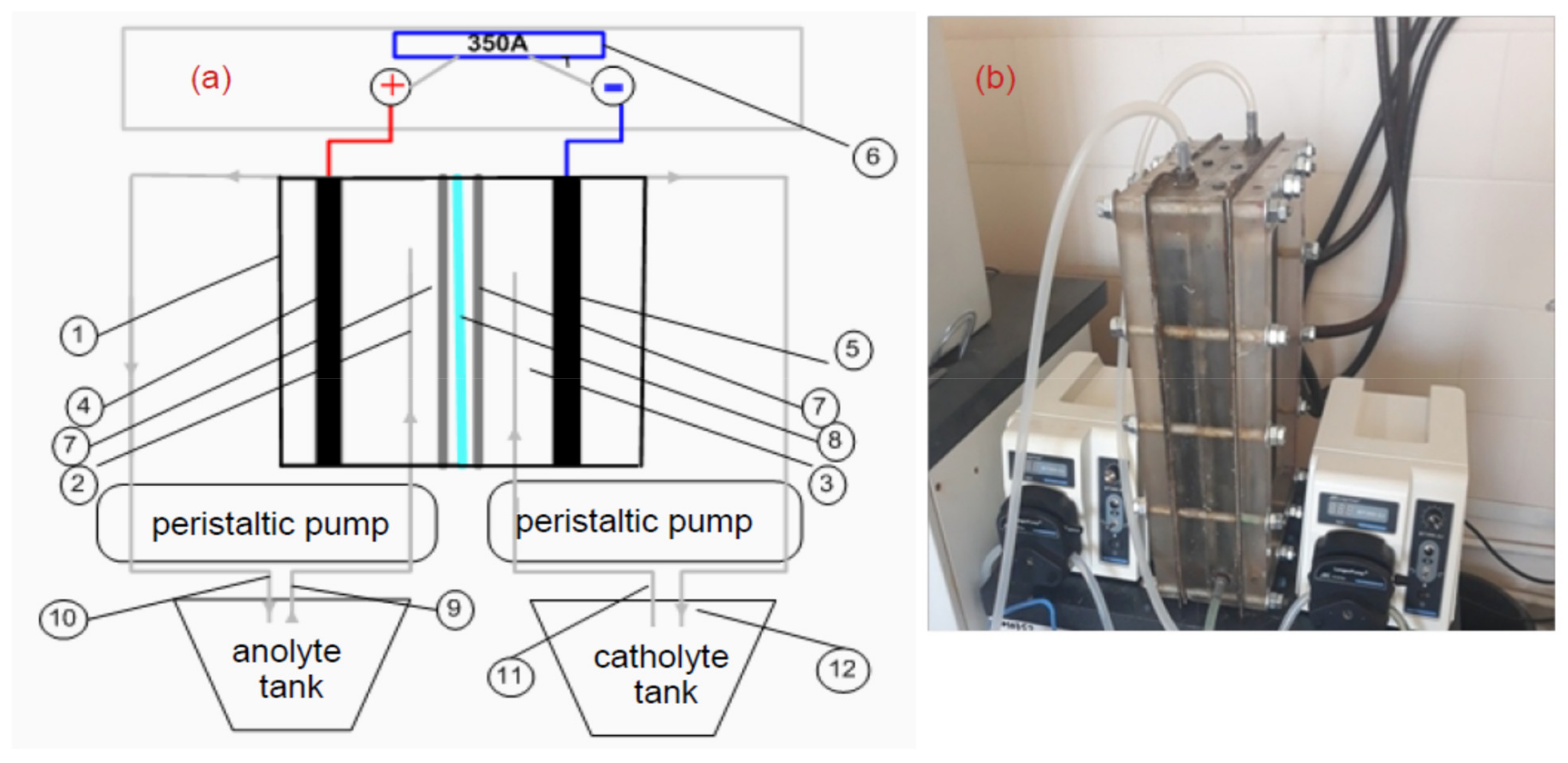
The Course of the Experiment
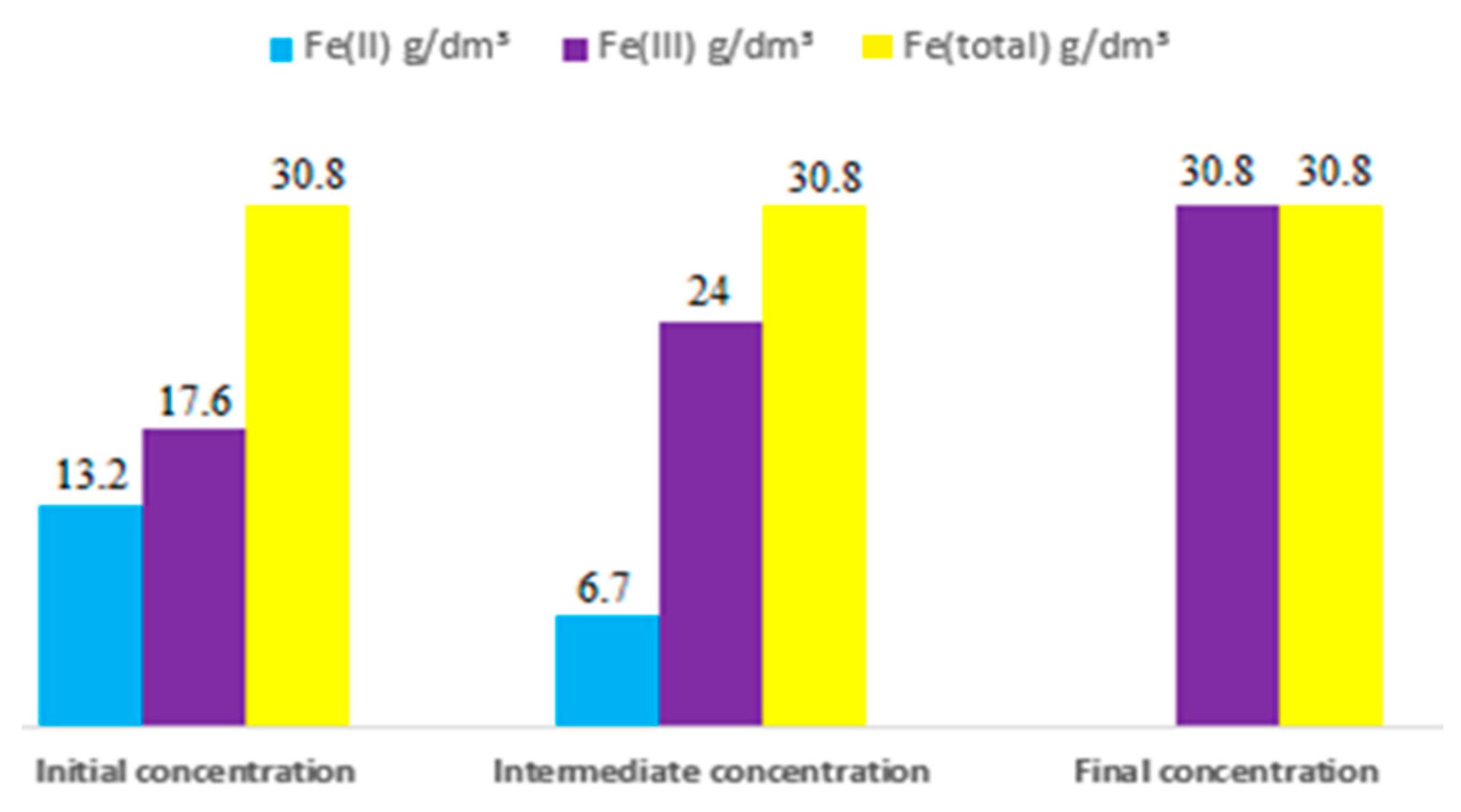
First type of the experiment with preliminary precipitation of Fe(III).
After preliminary precipitation of Fe(III) hydroxide compounds, the pulp was filtered on the druk-filter at a pressure of 4–5 atm, the resulting solutions were sent for electrooxidation in the anode chamber of the electrolyzer, followed by precipitation of all iron by neutralization with lime (the second stage of precipitation).
The electrooxidation of iron in the solution obtained after the first stage of deposition (the content of Fe(III) 3.19 g/dm3, total iron 11.2 g/dm3) was carried out in the anode chamber of a flow electrolyzer at the current density of 350 A/m2 and a circulation rate 2 dm3/h.
Second type of the experiment without preliminary deposition of Fe(III).
The cathode chamber was filled with sulfuric acid (catholyte), the concentration of which was 10 g/dm3, and the anode chamber was filled with the initial solution of the composition g/dm3: 123.8—zinc; 25–30—iron; 2–3—copper; 0.02—nickel. When an electric current is applied to the anode, ferrous iron is oxidized to ferric iron, in addition, the oxidation process takes place due to oxygen, which is released at the anode. Sulfate ions moved through the membrane from the cathode chamber to the anode chamber. As a result of the reaction of ferrous sulfate, sulfuric acid and oxygen, ferric sulfate was formed. Consequently, the divalent form of iron in ionic and molecular form is converted into the trivalent form of iron according to the following reactions (1)–(3):
H2O − 2e → 2H+ + 1/2 O2
2H+ + SO42− → H2SO4
4 Fe2+ + O2 + 4H+ → 4Fe3+ + 2H2O

3. Results

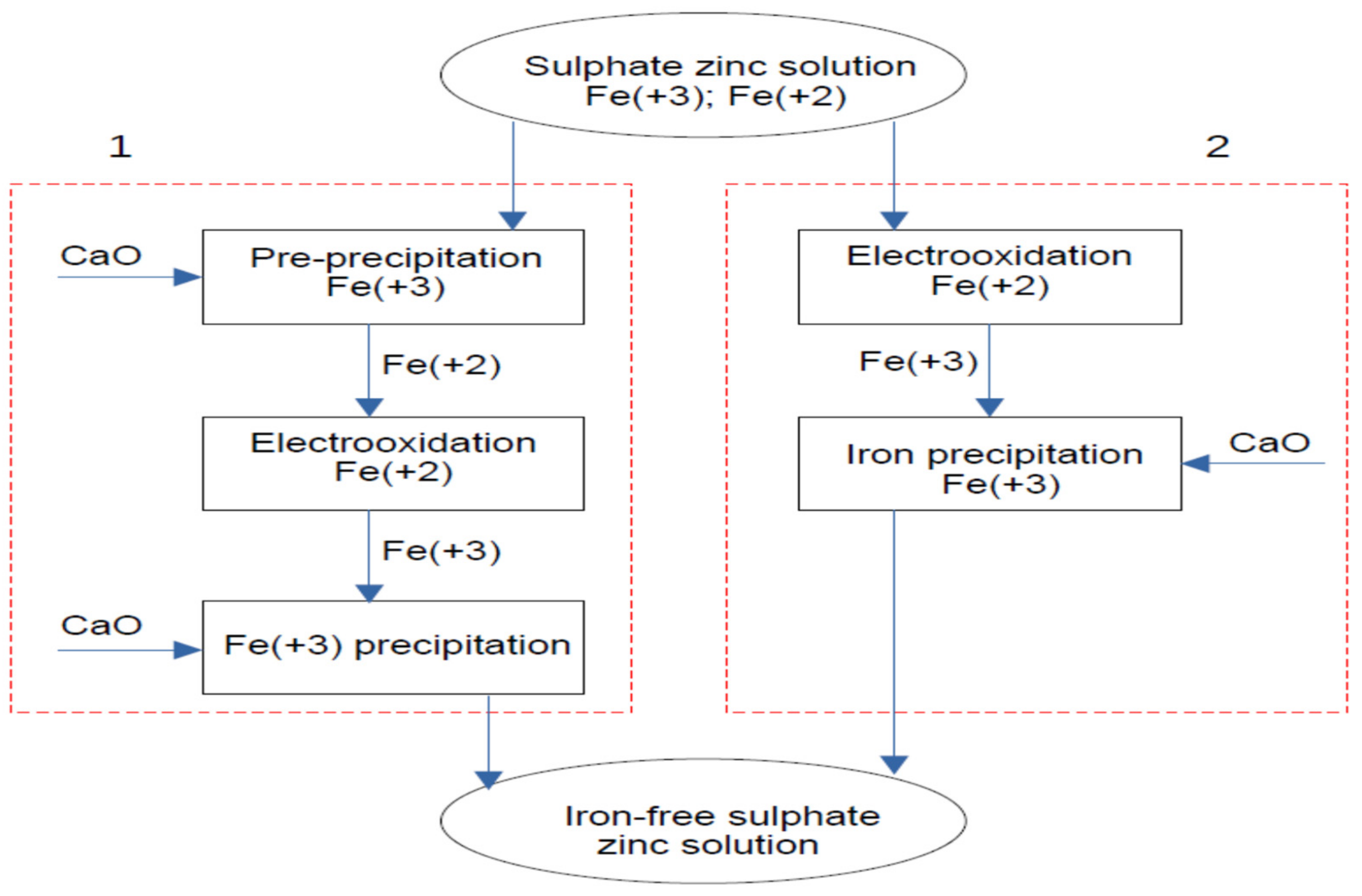
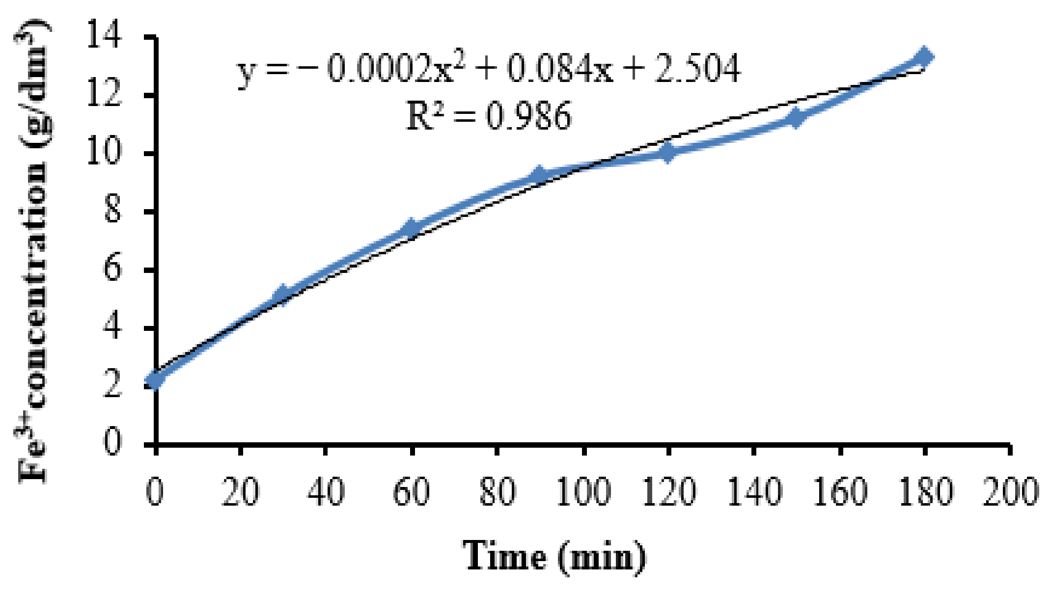
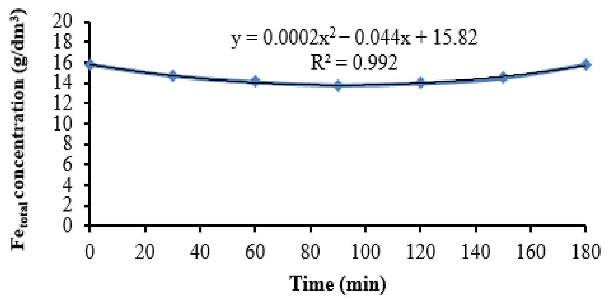
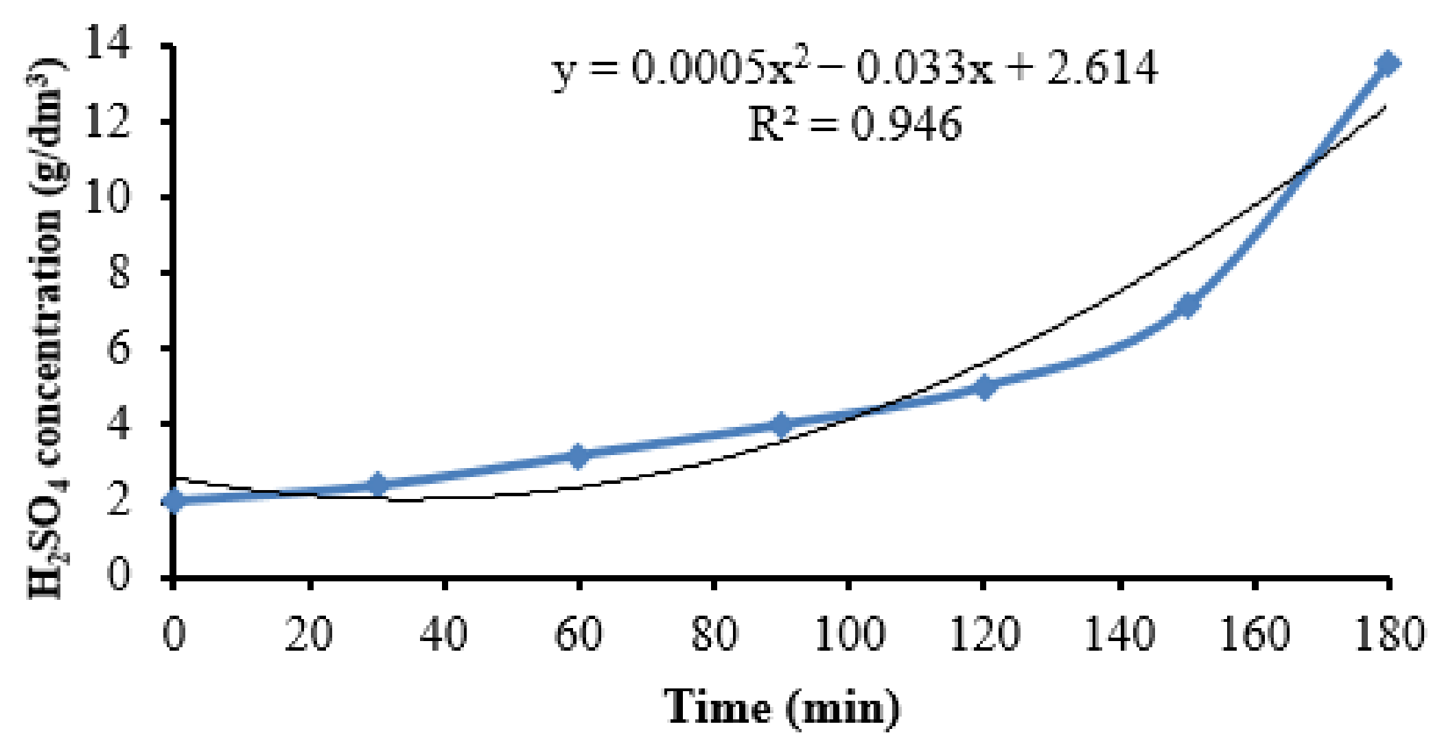
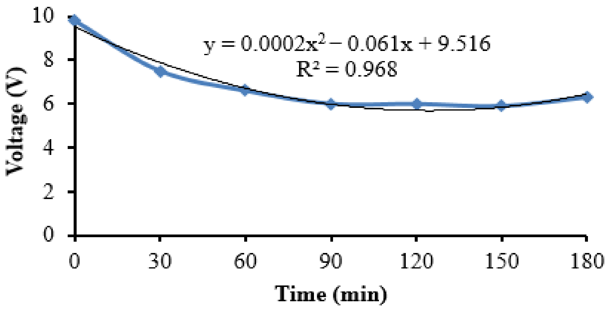
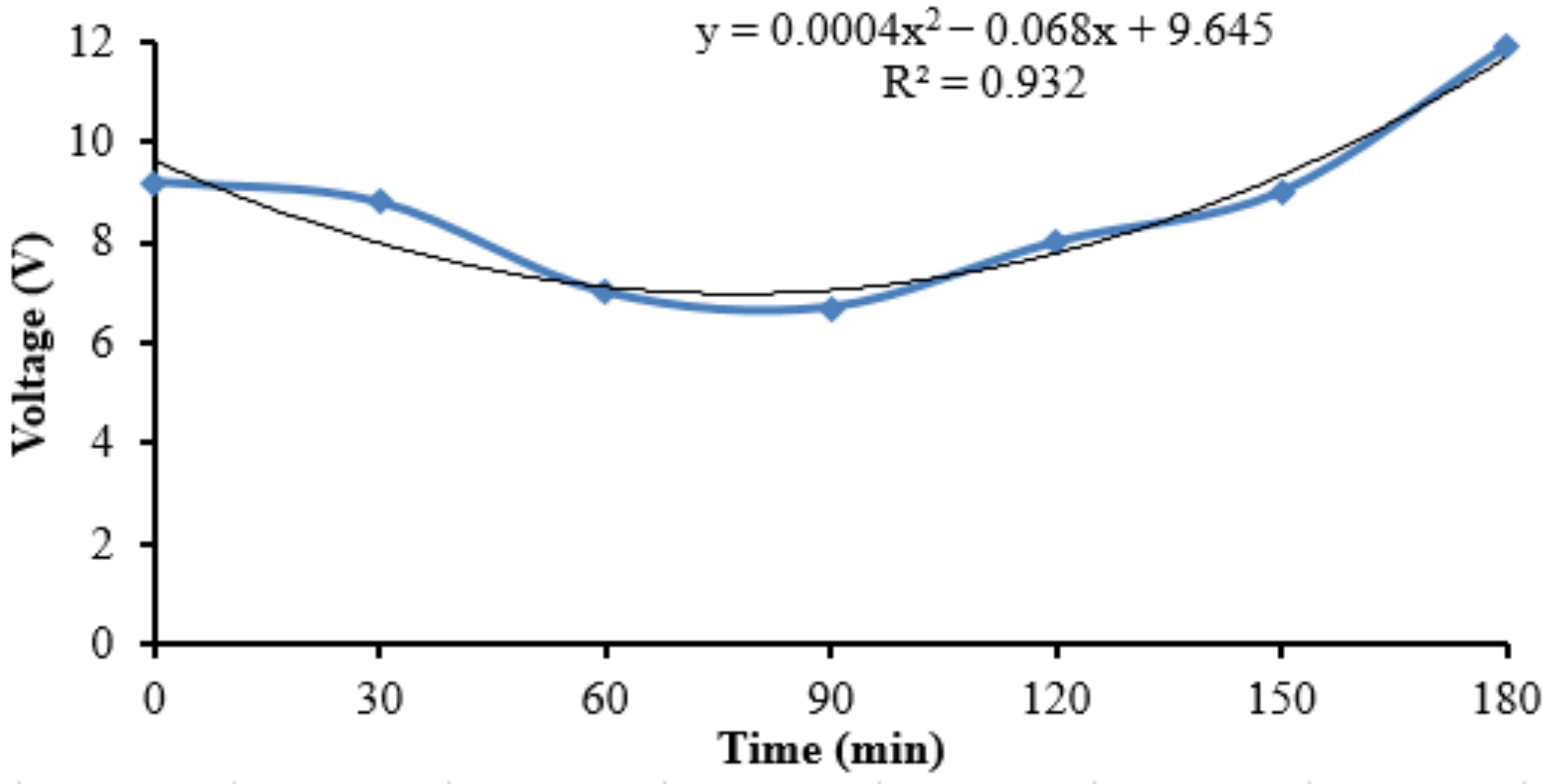
3.1. Stage 1 of the Experiment

Preliminary precipitation of Fe(III) with lime. The final content of Fe(III) in the solution after the operation of preliminary precipitation by neutralization with lime to pH 3.2 was 3.19 g/dm3. The pulps obtained as a result of neutralization of the initial working solution were distinguished by an extremely low filtration rate even when the pressure in the druk-filter was increased to 5 atm, which is associated with the presence of a significant amount of Fe(II) ions in the solution and, as a result, the formation of complex hydrocompounds of ferrous iron, in particular, basic salts, characterized by extreme dispersity and a tendency to form amorphous difficult-to-filter phases [32]. Figure 4 shows the dependence of the content of Fe(III) in the solution on the pH of the medium at preliminary precipitation of Fe(III) with lime. The dependence of the content of Fe(III) in solution on pH during neutralization with lime is close to linear, the final pH value in the experiments, equal to 3.2, is due to the possibility of precipitation of hydrated zinc compounds and impurities on the surface of CaO particles, an increase in the consumption of the latter, dilution of the solution formed by the neutralization reaction water and possible deterioration of filterability of pulps.
Subsequent electrodeposition. Under the above conditions, changing the content of ferric iron in solution during electrooxidation in the anode chamber is shown in Figure 5. The content of sulfuric acid in the solution increases, which is associated with the occurrence of an electrochemical reaction of oxygen evolution at the anode as a result of water decomposition. The rate of iron oxidation was about 2.7–3.1 g/dm3 per hour, and the time required for complete oxidation of iron exceeded 3 h.
The concentration of total iron during electrooxidation practically does not change (Figure 6), which indicates the absence of the possibility of the formation of poorly soluble iron compounds during the process.
During the electrooxidation of iron in the flow cell, the content of sulfuric acid in the solution increases (Figure 7), which is associated with the occurrence of an electrochemical reaction of oxygen evolution at the anode as a result of water decomposition. The determination of H2SO4 was carried out by direct titration with a standard alkali solution. The pH at the equivalence point is 7. Methyl orange [33] was used as an indicator.
The change in voltage across the cell is shown in Figure 8. The voltage across the cell stabilizes at 6–6.5 V within 40–50 min after the start of the process, which is associated with the operation of the cell without circulation of the solution during this period of time.
Due to the poor filterability of the pulps of the first stage of iron precipitation, attempts were made to carry out the electrooxidation of iron directly in the real Hydropolymet solution, bypassing the stage of preliminary precipitation of Fe(III) hydroxide compounds.
According to [32], in the presence of Fe(II) ions, X-ray amorphous Fe(OH)2 aggregates are formed, the size of which does not exceed 5 μm, while iron sulfates form well-crystallized FeOOH (ferric iron oxyhydroxides) three modifications, with a certain particle morphology. The average size of the formed crystals depends on the completeness of the oxidation process, therefore, affects the filterability of the resulting precipitate.

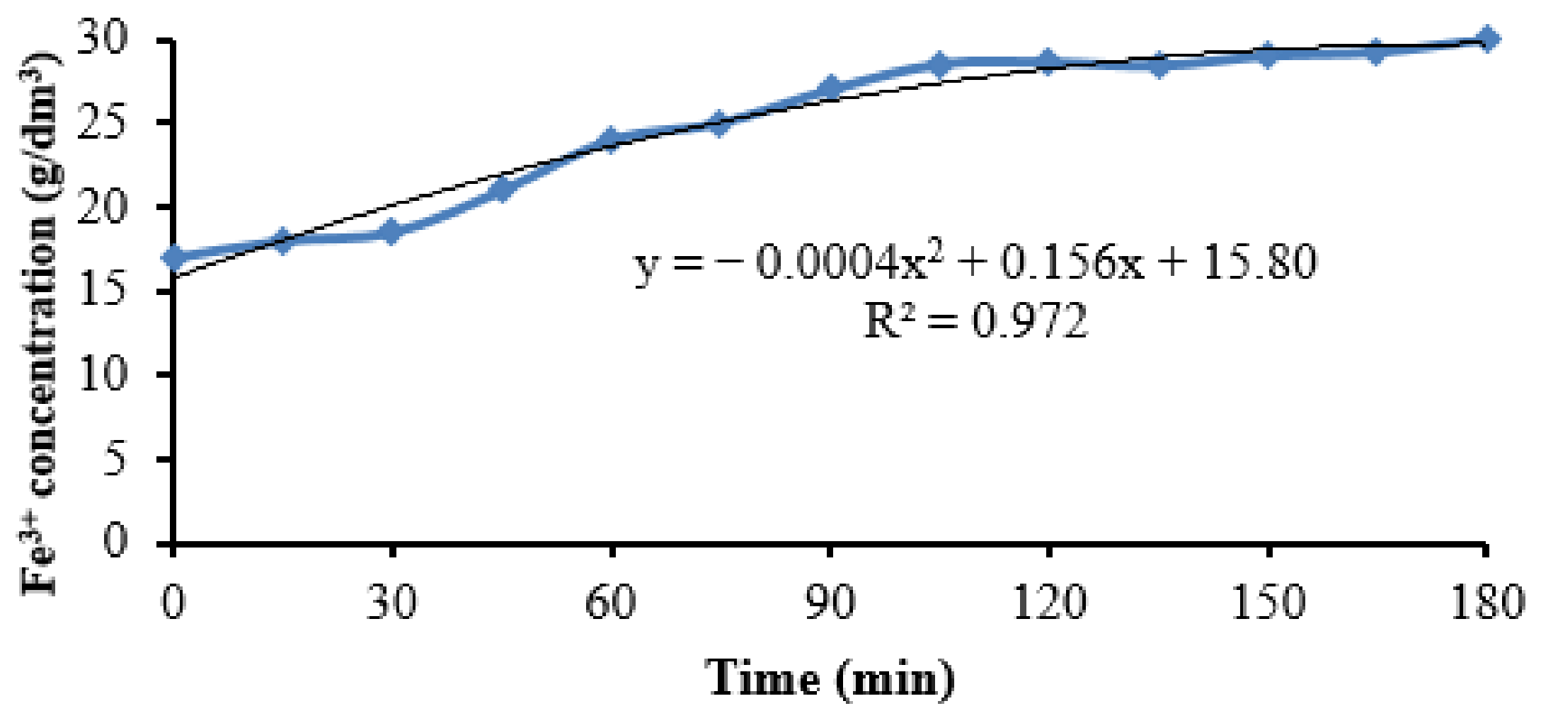
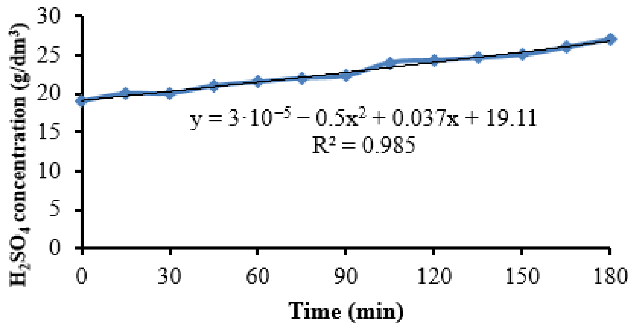
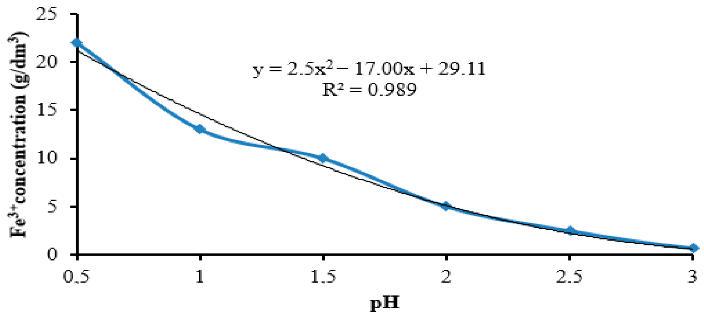
3.2. Stage 2 of the Experiment

In the second series of experiments, a real solution was used as the anolyte, Hydropolymet obtained by leaching low-grade zinc concentrates. The process of electrooxidation of the working solution was carried out in the anode chamber of the flow cell at a current density of 350 A/m2 and a circulation rate of 2 dm3/h. The change in Fe(III) concentration during electrooxidation is shown in Figure 9.
Figure 8 shows that almost complete oxidation of iron occurs within 90–100 min from the start of the process, which indicates the efficiency of using the working solution as an anolyte without preliminary precipitation of Fe(III). Accordingly, there is a change in the content of total iron in the solution. The change in the acidity of the anolyte (Figure 10) is more noticeable than in the experiments with preliminary precipitation of iron, which may be due to the excessive duration of the experiment, i.e., operation of the electrolytic cell at almost complete oxidation of Fe(II) to Fe(III).
The increase in the voltage on the bath (Figure 11) after 90–100 min is associated with the completion of the process of anodic oxidation of iron and the increase in the proportion of the water decomposition reaction in the solution with increasing acidity.
Precipitation of Fe(III) hydrated compounds after direct electrooxidation of the working solution was carried out according to the same procedure as two-stage precipitation with intermediate electrooxidation of iron.
The dependence of the content of Fe(III) in the solution on pH during the precipitation of iron from solutions after electrooxidation of real working solutions of Hydropolymet is shown in Figure 12. It is obvious that the neutralization of solutions to pH 3.5 is sufficient for the quantitative precipitation of iron in the form of hydrated compounds.
Precipitate obtained after Fe(III) precipitation from direct electrooxidation solutions (Figure 13) was characterized by good filterability (filtration rate 1.5–2 m3/m2·h) and greater compactness.
Thus, direct electrooxidation of sulfate zinc solutions obtained by leaching low-quality zinc concentrates in the anode chamber of the flow electrolyzer provides good filterability of precipitates after hydrolytic precipitation, since this solution does not contain Fe(II) ions, the presence of which leads to significant difficulties in the operations of separating solid and liquid phases. The average indicators for conducting the electrooxidation process are shown in Table 2.
The obtained experimental values of the concentration of iron in the solution are shown in Figure 14.
As a result of laboratory studies using the membrane electrolyzer, ferrous iron in sulfate zinc solutions was completely converted into ferric iron. Further tests will be carried out to get a complete purification from the remaining impurities.
The next stage of the study is to determine the conditions and parameters for the removal of electropositive impurities (copper cations, in particular) in the cathode chamber of the electrolytic cell by electrocarburizing.

4. Conclusions

It has been established for the first time that during the preliminary precipitation of Fe(III) ions from real sulfate solutions, difficult-to-filter pulps are obtained, and direct electrooxidation of sulfate zinc solutions in the anode chamber of the flow membrane electrolyzer provides good filterability of precipitation after hydrolytic precipitation of iron, since there are no ions in this solution. Fe(II), the presence of which leads to significant difficulties in the operations of separating the solid and liquid phases. This makes it possible to exclude the thickening operation from the technological scheme. The degree of oxidation of iron during the test period was 99.8–99.9%. The residual concentration of iron after precipitation from solutions obtained after electrochemical oxidation in the form of oxide and hydroxide compounds was less than 0.01 g/dm3.

Author Contributions

Conceptualization, L.L., Z.O. and N.K.; Methodology, S.M. and O.A.; Software, L.L.; Validation, L.L., Z.O., G.D., S.M. and O.A.; Formal analysis, L.L., Z.O., G.D. and O.A.; Investigation, L.L., Z.O. and N.K.; Resources, L.L., G.D. and O.A.; Data curation, L.L., Z.O., N.K. and O.A.; Writing—original draft preparation, L.L., Z.O., N.K., S.M. and O.A.; Writing—review and editing, L.L., Z.O., N.K., S.M., G.D. and O.A.; Visualization, L.L., Z.O. and G.D. All authors have read and agreed to the published version of the manuscript.

Funding

This research received no external funding.

Data Availability Statement

Not applicable.

Conflicts of Interest

The authors declare no conflict of interest.

References

  1. Seksenova, N.; Bykov, R.; Mamyachenkov, S.; Daumova, G.; Kozhakanova, M. Optimization of Conditions for Processing of Lead–Zinc Ores Enrichment Tailings of East Kazakhstan. Metals 2021, 11, 1802. [Google Scholar] [CrossRef]
  2. Li, Y.; Liu, H.; Peng, B.; Min, X.; Hu, M.; Peng, N.; Lei, J. Study on separating of zinc and iron from zinc leaching residues by roasting with ammonium sulphate. Hydrometallurgy 2015, 158, 42–48. [Google Scholar] [CrossRef]
  3. Grudinsky, P.; Pankratov, D.; Kovalev, D.; Grigoreva, D.; Dyubanov, V. Comprehensive Study on the Mechanism of Sulfating Roasting of Zinc Plant Residue with Iron Sulfates. Materials 2021, 14, 5020. [Google Scholar] [CrossRef] [PubMed]
  4. Raghavan, R.; Mohanan, P.; Verma, S. Modified zinc sulphate solution purification technique to obtain low levels of cobalt for the zinc electrowinning process. Hydrometallurgy 1999, 51, 187–206. [Google Scholar] [CrossRef]
  5. Niu, Z.; Li, G.; He, D.; Fu, X.; Sun, W.; Yue, T. Resource-recycling and energy-saving innovation for iron removal in hydrometallurgy: Crystal transformation of ferric hydroxide precipitates by hydrothermal treatment. J. Hazard. Mater. 2021, 416, 125972. [Google Scholar] [CrossRef]
  6. Hoeber, L.; Steinlechner, S. A comprehensive review of processing strategies for iron precipitation residues from zinc hydrometallurgy. Clean. Eng. Technol. 2021, 4, 100214. [Google Scholar] [CrossRef]
  7. Fu, X.; Niu, Z.; Lin, M.; Gao, Y.; Sun, W.; Yue, T. Strengthened Oxygen Oxidation of Ferrous Ions by a Homemade Venturi Jet Microbubble Generator towards Iron Removal in Hydrometallurgy. Minerals 2021, 11, 1342. [Google Scholar] [CrossRef]
  8. Lahtinen, M.; Lehtinen, L.; Takala, H.A. Method for Precipitating Iron from a Zinc Sulphate Solution as Hematite. Patent EP1453985B1, 13 November 2007. Available online: https://patents.google.com/patent/EP1453985B1/ja (accessed on 18 May 2010).
  9. Claassen, J.O.; Sandenbergh, R.F. Particle growth parameters in the precipitation of metastable iron phases from zinc-rich solutions. Hydrometallurgy 2006, 84, 165–174. [Google Scholar] [CrossRef]
  10. Loan, M.; Parkinson, G.; Newman, M.; Farrow, J. Iron oxy-hydroxide crystallization in a hydrometallurgical residue. J. Cryst. Growth 2002, 235, 482–488. [Google Scholar] [CrossRef]
  11. Onalbayeva, Z.S.; Kulenova, N.A.; Mamyachenkov, S.V.; Anisimova, O.S. Problems of purification of sulfate zinc solutions with high iron content // Proceedings of the XII “Metallurgy of non-ferrous, rare and noble metals” within the framework of the X International Congress “Non-ferrous metals and minerals-2018”. Krasnoyarsk 2018, 1329–1332. (In Russian) [Google Scholar]
  12. Karimov, K.; Kritskii, A.; Naboichenko, S.; Kolmachikhina, O.; Rogozhnikov, D. Autoclave Precipitation of Iron From Zinc Sulfate Solutions. KnE Mater. Sci. 2017, 2, 76–82. [Google Scholar] [CrossRef]
  13. Qin, S.-C.; Jiang, K.-X.; Wang, H.-B.; Zhang, B.-S.; Wang, Y.-F.; Zhang, X.-D. Research on Behavior of Iron in the Zinc Sulfide Pressure Leaching Process. Minerals 2020, 10, 224. [Google Scholar] [CrossRef] [Green Version]
  14. Wang, Y.; Jiang, K.; Ma, H. The Behavior of Zinc and Iron in Neutralized Residue During Pressure Leaching. Min. Metall. Explor. 2022, 39, 847–854. [Google Scholar] [CrossRef]
  15. Soltani, F.; Darabi, H.; Aram, R.; Ghadiri, M. Leaching and solvent extraction purification of zinc from Mehdiabad complex oxide ore. Sci. Rep. 2021, 11, 1566. [Google Scholar] [CrossRef]
  16. Yan, H.; Chai, L.; Peng, B.; Li, M.; Peng, N.; Hou, D. A novel method to recover zinc and iron from zinc leaching residue. Miner. Eng. 2014, 55, 103–110. [Google Scholar] [CrossRef]
  17. Bisang, J.M. Theoretical and Experimental Studies of the Dynamic Behaviour of Plug Flow Electrochemical Reactors for a Step Change in Flow Rate. J. Appl. Electrochem. 2001, 31, 403–409. [Google Scholar] [CrossRef]
  18. Bisang, J.M. Dynamic behaviour of electrochemical reactors for a step change in the inlet concentration under galvanostatic or potentiostatic control. J. Appl. Electrochem. 1998, 28, 1035–1040. [Google Scholar] [CrossRef]
  19. Gao, R.; Benetton, X.D.; Varia, J.; Mees, B.; Du Laing, G.; Rabaey, K. Membrane electrolysis for separation of cobalt from terephthalic acid industrial wastewater. Hydrometallurgy 2020, 191, 105216. [Google Scholar] [CrossRef]
  20. Abou-Shady, A.; Peng, C.; Almeria, O.J.; Xu, H. Effect of pH on separation of Pb (II) and NO3 from aqueous solutions using electrodialysis. Desalination 2012, 285, 46–53. [Google Scholar] [CrossRef]
  21. Banasiak, L.J.; Schäfer, A.I. Removal of boron, fluoride and nitrate by electrodialysis in the presence of organic matter. J. Membr. Sci. 2009, 334, 101–109. [Google Scholar] [CrossRef] [Green Version]
  22. Klahr, B.; Gimenez, S.; Fabregat-Santiago, F.; Bisquert, J.; Hamann, T.W. Electrochemical and photoelectrochemical investigation of water oxidation with hematite electrodes. Energy Environ. Sci. 2012, 5, 7626. [Google Scholar] [CrossRef]
  23. Fomchenko, N.V.; Muravyov, M.I. Effect of sulfide mineral content in copper-zinc concentrates on the rate of leaching of non-ferrous metals by biogenic ferric iron. Hydrometallurgy 2019, 185, 82–87. [Google Scholar] [CrossRef]
  24. Liu, F.; Liu, Z.; Li, Y.; Wilson, B.P.; Lundström, M. Recovery and separation of gallium(III) and germanium(IV) from zinc refinery residues: Part I: Leaching and iron(III) removal. Hydrometallurgy 2017, 169, 564–570. [Google Scholar] [CrossRef] [Green Version]
  25. Gueccia, R.; Aguirre, A.R.; Randazzo, S.; Cipollina, A.; Micale, G. Diffusion Dialysis for Separation of Hydrochloric Acid, Iron and Zinc Ions from Highly Concentrated Pickling Solutions. Membranes 2020, 10, 129. [Google Scholar] [CrossRef]
  26. Zimmekman, P.; Tekinalp, O.; Deng, L.; Forsberg, K.; Wilhelmsen, O.; Burheim, O. Electrodialysis in Hydrometallurgical processes. In Rare Metal Technology 2020; Azimi, G., Forsberg, K., Ouchi, T., Kim, H., Alam, S., Baba, A.A., Eds.; The Minerals, Metals & Materials Series; Springer International Publishing: Cham, Switzerland, 2020; pp. 159–167. ISBN 978-3-030-36757-2. [Google Scholar] [CrossRef]
  27. Csicsovszki, G.; Kékesi, T.; Török, T.I. Selective recovery of Zn and Fe from spent pickling solutions by the combination of anion exchange and membrane electrowinning techniques. Hydrometallurgy 2005, 77, 19–28. [Google Scholar] [CrossRef]
  28. Dubrawski, M.; Czaplicka, M.; Mrozowski, J. The application of electrodialysis to the treatment of industrial copper and zinc electrolytes. Desalination Water Treat. 2014, 55, 389–400. [Google Scholar] [CrossRef]
  29. Badenhorst, W.D.; Rossouw, C.; Cho, H.; Kerres, J.; Bruinsma, D.; Krieg, H. Electrowinning of Iron from Spent Leaching Solutions Using Novel Anion Exchange Membranes. Membranes 2019, 9, 137. [Google Scholar] [CrossRef] [Green Version]
  30. Arguillarena, A.; Margallo, M.; Irabien, A.; Urtiaga, A. Life cycle assessment of zinc and iron recovery from spent pickling acids by membrane-based solvent extraction and electrowinning. J. Environ. Manag. 2022, 318, 115567. [Google Scholar] [CrossRef]
  31. Bonchev, P.R.; Panayot, R. Introduction to Analytical Chemistry; Publisher Khimiya: Leningrad, Russia, 1978; p. 496. (In Russian) [Google Scholar]
  32. Faizulloev, E.F. Processes of Formation of Iron (III) Hydroxocomplexes. Ph.D. Thesis, Tajik National University, Dushanbe, Russia, 2015; p. 132. (In Russian). [Google Scholar]
  33. GOST 31803-2012; Sulfuric Acid. Methods of Analysis. Publisher Standardinform: Moscow, Russia, 2019. Available online: https://files.stroyinf.ru/Data/530/53030.pdf (accessed on 1 October 2012).
Figure 1. Scheme of the experiment.
Metals 13 00088 g001
Figure 2. Scheme (a) and general view of the laboratory (b) installation of the membrane. Electrolyzer. 1—cell body; 2—cathode chamber; 3—anode chamber; 4—anode (lead + 1 % silver); 5—cathode (steel plate); 6—power supply; 7—perforated partitions for fixing the membrane; 8—anion-exchange membrane; 9—branch pipe for introducing the solution into the anode chamber; 10—branch pipe for removing the solution from the anode chamber; 11—branch pipe for introducing the solution into the cathode chamber; 12—branch pipe for removing the solution from the cathode chamber.
Metals 13 00088 g002
Figure 3. General view of the LR-2.ST type reactor (a) and the druk-filter (b).
Metals 13 00088 g003
Figure 4. Dependence of Fe(III) content in solution on the pH of the solution.
Metals 13 00088 g004
Figure 5. Change in the concentration of Fe(III) during electrooxidation in a flow cell.
Metals 13 00088 g005
Figure 6. Change in the concentration of Fetotal during electrooxidation in the flow cell.
Metals 13 00088 g006
Figure 7. Change in H2SO4 concentration during the electrooxidation in the flow cell.
Metals 13 00088 g007
Figure 8. Change in voltage on the cell.
Metals 13 00088 g008
Figure 9. Fe(III) concentration change during electrooxidation in the flow electrolyzer (solution without preliminary iron precipitation).
Metals 13 00088 g009
Figure 10. Change in the concentration of H2SO4 during electrooxidation in the flow electrolyzer (solution without preliminary precipitation of iron).
Metals 13 00088 g010
Figure 11. Changing the voltage on the cell.
Metals 13 00088 g011
Figure 12. Dependence of Fe(III) content in solution on the pH.
Metals 13 00088 g012
Figure 13. Precipitate obtained after Fe(III) precipitation from direct electrooxidation solutions.
Metals 13 00088 g013
Figure 14. The concentration of iron in the solution after oxidation in the electrolyzer.
Metals 13 00088 g014
Table 1. Chemical composition of the pregnant leaching solution.
ElementZnFeCuNiCoAsCdIn
Content, %10.193.570.2430.00130.000630.0033010.05530.000311
Table 2. Average indicators for carrying out the electrooxidation process.
Current Density, A/m2Electrolyte Feeding Rate,
dm3/min
The Initial Composition of the Electrolyte Fe2+, g/dm3Initial pH Value of the ElectrolyteExperiment Duration, min
256017.2080.5180
Disclaimer/Publisher’s Note: The statements, opinions and data contained in all publications are solely those of the individual author(s) and contributor(s) and not of MDPI and/or the editor(s). MDPI and/or the editor(s) disclaim responsibility for any injury to people or property resulting from any ideas, methods, instructions or products referred to in the content.

