
Influence of Microstructure on the Mechanical Properties and Polishing Performance of Large Prehardened Plastic Mold Steel Blocks

Institute for Special Steels, Central Iron and Steel Research Institute, Beijing 100081, China
*
Author to whom correspondence should be addressed.
Metals 2024, 14(4), 477; https://doi.org/10.3390/met14040477
Submission received: 5 March 2024
/
Revised: 9 April 2024
/
Accepted: 11 April 2024
/
Published: 19 April 2024
Abstract
:The microstructures throughout a 696 × 1360 mm cross-section of an ISO 1.2738 prehardened steel block for a plastic mold were characterized via optical and electron microscopy and electron backscatter diffraction. The hardness, strength, and polishing performance of the steel block were also tested. The results showed that the microstructure of the steel bloom from the edge to the core consisted of tempered sorbite, tempered bainite, and pearlite microstructures. Abnormal upper bainite and coarse carbides were also found. The bloom sections with hardness values of 37.4 to 39.3 HRC comprised tempered sorbite and bainite. The hardness of the core was approximately 36.5 HRC due to the presence of pearlite. The tensile and yield strengths were the same in the edge and middle areas mainly owing to tempered sorbite. The polishing performance was affected by the microstructure. Tempered sorbite produced the best polishing performance due to its fine and uniform microstructure, whereas that of tempered bainite and pearlite, which contained large carbide particles and mixed phases, was worse.
1. Introduction
The plastic molds used for plastic automotive components, such as bumpers and dashboards, are commonly machined from large prehardened steel blocks that are usually more than 600 mm thick. ISO 1.2738 steel (Fushun Special Steel Co., Ltd., Fushun, China) is the most widely used for these large steel blocks [1]. Due to these large dimensions, heat treatment produces mixed microstructures, which continuously vary from the quenched and tempered surface to the core. Firrao [2] reported that the dimensions of steel blooms frequently exceed the critical hardenability index of 1.2738 for steel. Thus, for large oil-quenched blooms, the microstructure differs at different depths, which is affected by the subsequent tempering. The performance indicators, such as the hardness, tensile properties, toughness, and polishing performance, of different microstructures differ. When the prehardened steel used for a plastic mold is manufactured into the mold cavity, the interior becomes the working surface, and microstructures in the original bloom can be found at different positions in the mold face [3]. Thus, the influence of the microstructure on the mechanical properties and the microstructure distribution at different positions in the steel block must be studied. Meng [4] analyzed the microstructure and mechanical properties of lower bainite and tempered martensite in JIS SK5 steel (Fushun Special Steel Co., Ltd.) (0.78C-0.21Si-0.45Mn-0.16Cr-0.002Mo). At the same hardness, lower bainite was tougher and more ductile than tempered martensite. However, as bainite laths are larger than martensite plates, lower bainite has a lower yield strength. Hoseiny et al. [5] studied the effect of microstructure changes on the hardness of 523 × 263 mm Nimax steel (Uddeholms AB, Hagfors, Sweden) (0.1C-0.26Si-2.48Mn-3.07Cr-1.0Ni-0.28Mo-0.017V). They found that the volume fraction of the autotempered martensite changed from 10% to 5% from the surface to center of the bloom, respectively. Despite this and the finer microstructure at the surface, the hardness was practically constant over the cross-section of the bloom. Min et al. [6] designed a copper-bearing nonquenched plastic mold steel (0.18C-0.3Si-1.5Mn-1.2Cr-0.2Mo-1.2Cu); the microstructure was mainly composed of bainite and ferrite after prehardening. After heat treatment, the characteristics of microstructure can contribute to the hardness of the test steel. Saeidi et al. [7] found that at room temperature and under the same hardness conditions, a mixed bainite + ferrite microstructure was more ductile and had higher impact toughness but a weaker yield and tensile strength than a mixed martensite + ferrite microstructure and full bainite. Zhang et al. [8] investigated the correlation between the impact toughness and microstructural characteristics of a large bainitic steel bloom. The toughness of the bloom core decreased with the increase in the proeutectoid ferrite content and the coarsening of tempered martensite–austenite constituents compared with the bloom surface. The presence of proeutectoid ferrite decreases steel toughness via its effects on the precipitation of carbide, the formation of martensite–austenite constituents, and the transformation of bainite. The relatively large tempered martensite–austenite constituents are conducive to microcrack nucleation and propagation. Shiou et al. [9] conducted an ultraprecision surface treatment of NAK80 mold steel (Daido Steel Co., Ltd., Nagoya, Japan) (0.18C-0.3Si-1.2Mn-0.42Ni-0.28Mo), which reduced the surface roughness (Ra) of the steel from 0.06 to 0.016 μm. However, none of these studies thoroughly analyzed the main reasons for and corresponding mechanisms that affect the polishing performance of NAK80 plastic mold steel.
The above review shows that although reports have been published on plastic mold steel with a large cross-section, the content and analyses are still not specific and in-depth enough, which has limited the development of plastic mold steels. Therefore, prehardened plastic mold steel was selected as the study object; the microstructure distribution in a large steel block and the corresponding effect of these microstructures on its mechanical properties and polishing performance were investigated.
2. Materials and Methods
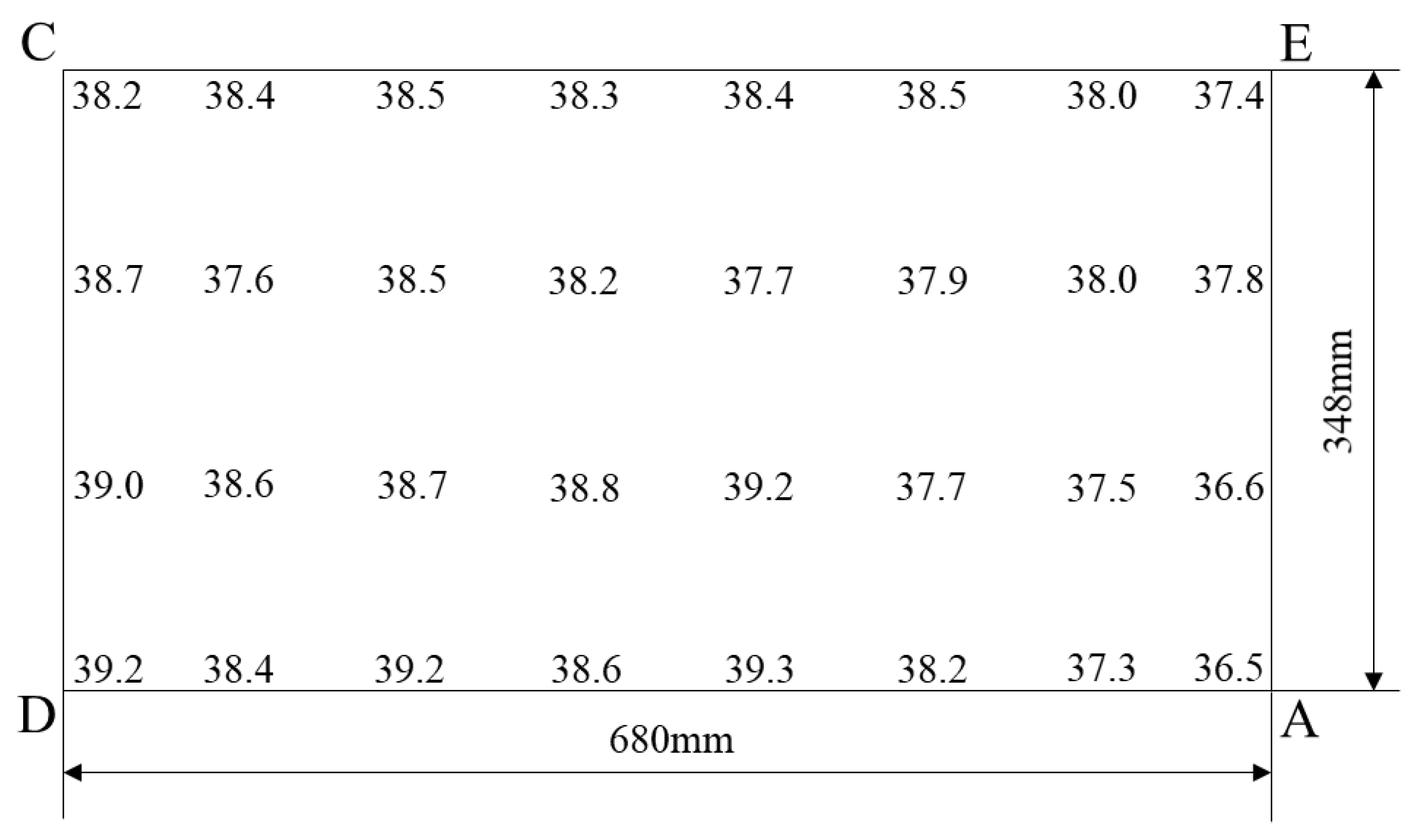
The chemical composition (wt. %) of the tested steel for a prehardened large plastic mold is presented in Table 1. A steel bloom with sectional dimensions of 696 mm (T) × 1360 mm (W) was forged from an approximately 36 t ingot, which was prehardened and heat-treated with 930 °C quenching and tempered twice at 510 °C. Specimens of 348 mm (T) × 680 mm (W) × 20 mm (L) were obtained from the middle of the bloom (area ACDE in Figure 1), where T, W, and L are the thickness, transverse, and longitudinal directions, respectively. Positions A, B, and C represent the steel core, ¼, and edge positions of the bloom, respectively. The microstructure and Rockwell hardness (Newage Testing Instruments, Horsham, PA, USA) were examined in fixed intervals in the width and thickness directions along the cross-section from the surface to core. The AE line was divided into four equal parts, and the AD line was divided into eight parts to select the specimens. An FR-3E Rockwell hardness tester (Advanced Test Equipment Corp., San Diego, CA, USA) was used to test the hardness of the samples. Each sample was tested three times, and the average was used as the hardness value.
The specimens for mechanical property testing were machined from the core to the surface as positions A, B, and C. The polishing performance was examined using an Agilent Technologies 5100 atomic force microscope (AFM) (Agilent, Santa Clara, Ca, USA) using the tapping mode. The surface roughness and three-dimensional morphology were measured, with a 50 × 50 μm scanning area. A microhardness tester (FM-300) (Future-Tech Corp., Tokyo, Japan) was used to test the hardness of the test steel, with a load of 200 g. The specimen surface was polished and etched. The hardness measurement was repeated three times, and the average was used as the microhardness value.
An Olympus GX51 optical microscope (OM) (Olympus Life Sciences, Tokyo, Japan), a Hitachi S-4300 scanning electron microscope (SEM) (Schaefer SEE Srl, Rovigo, Italy), an Oxford Nordlys F+ electron backscatter diffraction (EBSD) device (Oxford Instruments, Abingdon, UK), and a H800 transmission electron microscope (TEM) (JEOL Ltd., Tokyo, Japan) were employed to characterize the microstructure and study the carbide distribution of the 1.2738 steel. The metallographic specimens were mechanically polished and etched with 2% nitric acid solution. The TEM samples were cut into 0.3 mm thick slices and mechanically thinned to 0.05 mm. Finally, these samples were foiled in a twin-jet electropolisher.
3. Results
3.1. Characterization and Analysis
The microstructures of the blooms were examined at increasing depths along the diagonal direction. Local cooling rates were observed from the surface to the core owing to the large bloom size; during quenching, the sensitivity differed as a function of depth.
The microstructure of one bloom consisted of homogeneous tempered sorbite loser to the surface, as shown in Figure 2a and Figure 3a. The main microstructure was tempered bainite and upper bainite between the edge and core. The macrograph in Figure 2b shows dendrites, but most of the secondary dendrites were broken. The tempered bainite was further inspected with a high-powered OM, revealing a needle-like bainite morphology (arrow, Figure 3b). The abnormal microstructure in region A in Figure 2b comprises the parallel ferrite laths, extending outward in parallel along the direction of arrow Ⅰ (Figure 3c); the arrangement at the exit end of the arrowhead is orderly. We inferred that the ferrite may have nucleated at the grain boundary and grew into the grain. A needle shape can be observed at the end of arrow Ⅱ (Figure 3c), and the longest lath is essentially symmetrical, which is a typical feature of upper bainite [10,11]. This presented a microhardness value of up to 478 HV, higher than the 93 HV obtained for tempered bainite.
The microstructure at the bloom center contained tempered bainite (high hardness) and some lumps of fine pearlite (TB + P; low hardness). The macrograph in Figure 2c shows an inhomogeneous microstructure. The OM micrograph (Figure 3d) comprises dark and gray areas. The gray microstructure was tempered bainite, whereas the dark microstructure was fine pearlite. The results of the experiment revealed a microhardness of approximately 317 HV for fine pearlite, lower than the 47 HV obtained for tempered bainite.
Figure 4 shows the SEM observations. The microstructures at the edge mainly consisted of homogeneous tempered sorbite (Figure 4a), which comprised carbides uniformly distributed in the ferrite matrix. Figure 3b shows that the tempered bainite between the edge and core presented with needle-like bainite. The SEM results revealed that the needle-like bainite consisted of several relatively large-particle carbides (Figure 4b). The SEM micrograph in Figure 4c reveals parallel bainitic ferrite laths, which correspond to the abnormal microstructure in Figure 3c. We observed that the abnormal microstructure was upper bainite [12]. Additionally, the pearlite in the core exhibited the layered structural characteristics of carbides/ferrites (Figure 4d).
Figure 5 presents the TEM observations. The tempered sorbite at the edge of the steel bloom contained a high degree of recovered lath martensite, as shown in Figure 5a, whereas the martensite lath was unclear. Figure 5b presents the typical feature of inadequately tempered bainite. Figure 5c shows the parallel bainitic ferrite laths of the upper bainite, and Figure 5d depicts the typical mixed microstructure of lamellar pearlite and tempered bainite at the core of the steel bloom.
The microstructure of the 1.2738 steel bloom mainly consisted of tempered martensite close to the surface, tempered bainite in most of the bloom volume, and fine and ultrafine pearlite at the core. Furthermore, abnormal upper bainite and coarse carbide microstructures were found in the steel bloom due to element segregation [13,14].
To characterize the main microstructure of the 1.2738 steel bloom, the edge, one-quarter position, and core samples were examined via EBSD [15,16], and the results are presented in Figure 6. At the edge (Figure 6a), the fine martensite lath recovered to ferrite with the characteristics of tempered sorbite. Figure 6b shows the feathery profile of the bainite ferrite lath on both sides of the grain boundary (circle, Figure 6b), which are easily distinguishable. The microstructure at the one-quarter position was tempered bainite, which comprised coarse bainitic ferrite. The microstructure of the core (Figure 6c) was widely different from that at the edge and one-quarter positions; the EBSD results revealed many bainite ferrite laths (arrow, Figure 6c).
3.2. Mechanical Properties
Figure 7 presents the hardness distribution across the transverse one-quarter section of the 1.2738 steel bloom. The hardness between the edge and core widely fluctuated, with many points of high hardness. This occurred because the upper bainite was found in the middle area, between the edge and core. The maximum microhardness was 478 HV, being 93 HV higher than that of the tempered bainite in this area. We thus concluded that the main reason for the large fluctuation in hardness in the core was the segregation of the upper bainite. The minimum hardness in the core correlated to the existence of pearlite; the pearlite’s microhardness was 317 HV.
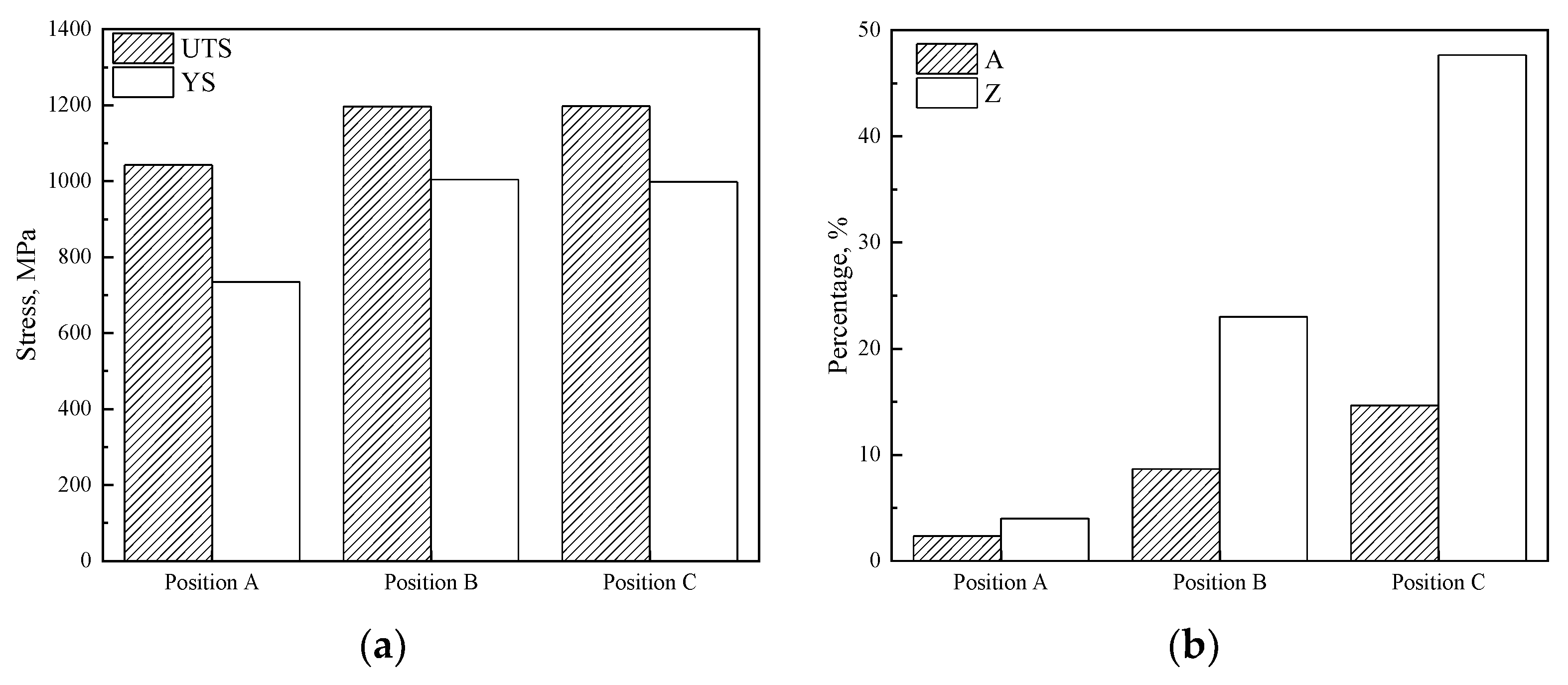
Figure 8 provides the tensile properties of the 1.2738 steel bloom at different positions, which, consistent with the hardness, were strongly influenced by the bloom depth and the corresponding microstructure. The yield strength (YS) and ultimate tensile strength (UTS) at the edge (Position C) were the same as those in the one-quarter position (Position B) but were lower in the core (Position A). However, the area (A) reduction and percentage elongation after fracture (Z) gradually, step-by-step, declined from the edge to the core, then sharply decreased in the core due to the presence of pearlite.
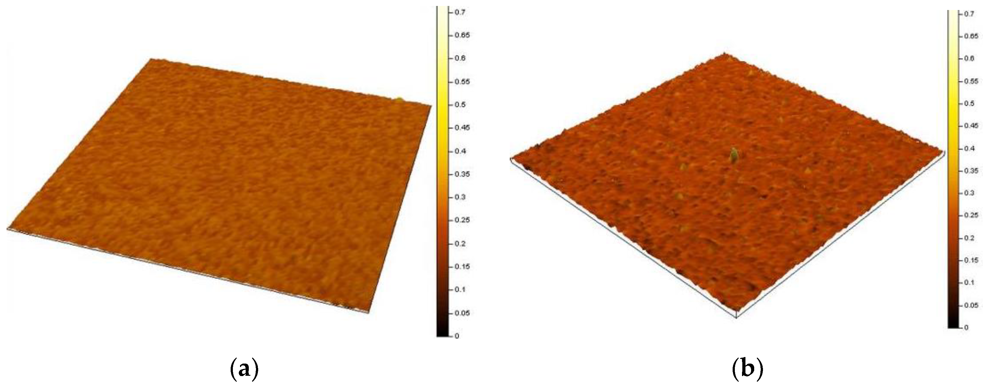
Figure 9 presents the three-dimensional morphology and Figure 10 is the partially five-fold-enlarged view of Figure 9. The three-dimensional morphology of the tempered sorbite, which is smooth and uniform, had a roughness of 30 nm (Figure 9a). This occurred due to the formation of lath fine martensite and carbides after edge quenching (presented in the EBSD, Figure 6a) and the subsequent formation of uniform tempered sorbite after tempering. The small, hard particle carbides of tempered martensite are prone to sliding and embedding in recovered ferrite during the polishing process [17]. This uniform microstructure is also subjected to shear stress formed during polishing, resulting in the smooth surface and high-quality polishing performance of tempered sorbite.
The three-dimensional morphology of tempered bainite is more convex and rough (roughness 42 nm) and contains small peaks (Figure 9b). With the increase in distance from the surface of the large-module 1.2738 steel bloom, the transition from tempered martensite to tempered bainite was as presented in Figure 3b,c. Due to the segregation of components [18], large carbide particles were found in the tempered bainite. Additionally, the rod-like carbide easily precipitated with a specific orientation in the bainitic lath. The tempered bainite lath in the core was thick (as presented in the EBSD, Figure 6b) compared with the tempered sorbite formed via edge martensite tempering. A thick lath forms anisotropy between the lath arms and slats, which can lead to uneven stress during polishing [19,20]. Furthermore, hard-point carbide does not plastically deform easily, and its deformation can be absorbed through bainite ferrite. If large-particle carbide is present in a steel bloom, pits can easily form on the polished surface. Moreover, when bainite ferrite is extruded by large-particle carbide, the stress at the lath boundary is uneven, and the bump could easily form at the lath boundary, which would affect the polishing performance.
The three-dimensional morphology of the mixed microstructure of pearlite and tempered bainite is shown in Figure 9c. The arrow in Figure 9c indicates a concave morphology, which had a microstructure characterized by pearlite with lower hardness. Figure 6c shows that pearlite grains with different cementite lamellae orientations and bainite ferrite laths formed in the same original austenite grains. These had an uneven microstructure, which affected the polishing performance. The pearlite was easily abraded during polishing, forming a depression. The ferrite and cementite of pearlite have different abilities to bear the ultimate stress during polishing, resulting in a convex and uneven polishing result. This can be observed from the three-dimensional shape of the locally enlarged drawing (Figure 10c). Therefore, the pearlite mixed in the bloom reduced the surface polishing performance.
The three-dimensional morphology of total pearlite is shown in Figure 9d. The polishing performance of the pearlite was poor, showing serious orange peeling in the polishing, which should be avoided.
Figure 9e displays several peaks and bulges in the three-dimensional shape of the mixed sorbite + granular carbide microstructure, and the granular characteristics in the locally enlarged area can be observed in Figure 10e. The large-granular carbide was difficult to abrade due to its high hardness during polishing, whereas the sorbite matrix and small-grain carbide were removed, resulting in a poor polishing effect [21].
4. Discussion
4.1. Mechanism of Formation of Cross-Sectional Microstructure Features
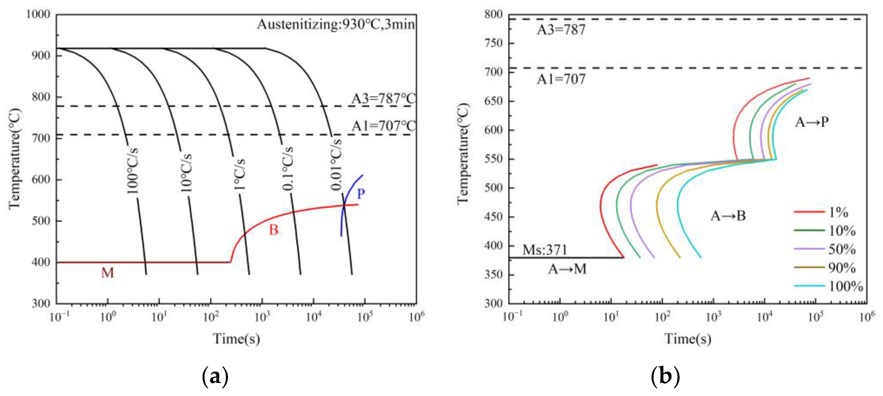
The experimental results showed that the differences in hardness, strength, and toughness between the surface and core of the large-cross-section 1.2738 plastic mold steel were caused by differences in the microstructure in the cross-sectional area. We analyzed the CCT and TTT curves calculated using JMatPro to further determine the reasons for the microstructure differences that arose during the pre-hardening of 1.2738 test steel; the results are shown in Figure 11. Pearlite transformation occurs when the cooling rate is below 0.01 °C/s and cooled to approximately 620 °C according to the continuous cooling transformation curve of the 1.2738 test steel in Figure 11a. When the cooling rate is between 0.01 and 10 °C/s, bainite transformation occurs between approximately 400 and 550 °C. When the cooling rate exceeds 10 °C/s, martensitic mainly transforms during cooling. Furthermore, the starting and ending lines of pearlite and bainite transformation are distributed over an extended period according to the TTT curve in Figure 11b [22,23].
During the prehardening process of 1.2738 plastic mold steel, the cooling rate of the outer surface (edge) is high due to the direct contact with the cooling medium, forming a microstructure mainly composed of martensite. However, the cooling rate gradually decreases with the increase in the centripetal distance due to the size effect, leading to the appearance of microstructures such as bainite (along the one-quarter diagonal) and pearlite (in the core) [24]. In addition, when the outer surface cools to ambient temperature, the temperature of the core may remain higher due to size factors. The core transfers heat to the edges through radiation and heat conduction, causing self-tempering at the edges and one-quarter of the diagonal, which have completed the transformation, forming microstructures such as tempered martensite and tempered bainite [25,26]. The core forms a pearlite-dominated microstructure due to the slow cooling rate.
4.2. Polishing Removal Mechanism
When polishing the surface of plastic mold steel, the plow formed during the sandpaper grinding stage meshes with the polishing cloth and is ground flat. The polishing process can be explained by the adhesive friction theory proposed by Bowden and Tabor [27]: When two surfaces contact under the action of compressive load, the protruding contact points have high potential pressure and plastically deform. These deformation points firmly adhere to the polished surface, forming a cohesive surface called adhesion or cold welding. When the polished surfaces slide against each other, the adhesive points are cut off, and the repeated effects are polished. According to simple adhesive friction theory, the adhesive friction force Fα is the shear force required to cut the metal bonding point for ideal elastic–plastic materials. Let the shear strength of the adhesive node be τb. The adhesive friction force is as follows:
In the formula, Fα is the adhesive friction; Aγ is the actual contact area; and τb is the material’s shear strength.
For most metal materials, the shear strength limit of metals τ0 and the yield limit of metals σy satisfy the following relationship:
τ0 is the shear strength limit of the metal; and σy is the yield limit of the metal.
During the polishing process, the surface protrusions peel off when the shear strength τb reaches the shear strength limit. So, the ultimate shear force F0 is expressed as follows:
According to Figure 8, the yield strengths Rp0.2 of the tempered martensite, tempered bainite, and pearlite were 885 MPa, 868 MPa, and 492 MPa, respectively. The same experimental sample was polished on a polishing machine with the same actual contact area using the same sandpaper and assuming the plow grooves had the same depth. The ultimate shear force F0 of a material is directly proportional to its yield strength; Formula (3) shows that when the actual contact area is the same, the larger the yield strength of the material, the larger the shear force required to remove the material, hindering its removal. Conversely, if the yield strength is weaker, less shear force is needed to remove the material. The sample with a mixed pearlite and tempered bainite microstructure had a higher yield strength than pearlite. Removing tempered bainite requires a larger shear force, and the shear force after the removal of pearlite was 43% lower than that after the removal of tempered bainite. This indicated the formation of pits during the polishing of pearlite.
The factors that affect polishing performance are relatively complex [28,29,30,31]. In this test steel, the roughness, strength, and hardness of the microstructure; the size of carbides; and the uniformity of carbide distribution were important factors that affected polishing performance. In large-module plastic die steel, the polishing performance of tempered sorbite is the best due to its fine microstructure and uniform distribution of carbide, whereas the polished surface of tempered bainite is rough due to factors such as coarse bainite ferrite laths and large carbide particles. The microsegregation in the core of the large module and the pearlite formed by the slow cooling rate during quenching also deteriorate the polishing performance.
5. Conclusions
- From our examination of a 1.2738 steel bloom, we found that tempered sorbite only occurred close to the surface, with its content steeply decreasing with depth. Tempered bainite was the prevalent constituent of the bloom. Pearlite gradually appeared at larger depths, and pearlite + tempered bainite was the main constituent in the core. Abnormal upper bainite microstructures and coarse carbides were also found in the steel bloom.
- The hardness values varied between 37.4 and 39.3 HRC throughout most bloom sections with the exception of a small core region. The hardness in the core was approximately 36.5 HRC due to the existence of pearlite.
- The polishing performance was strongly affected by the microstructure type. The best polishing performance was found for tempered sorbite, which occurred due to its fine and uniform microstructure. The polishing performance of the tempered bainite + pearlite microstructure, which contained large carbide particles and mixed microstructure, was worse than that of tempered sorbite. This was due to the inhomogeneity of these microstructures and the inhomogeneous deformation of polishing caused by the differences in the microstructure types.
Author Contributions
Conceptualization, H.C., J.Z. and D.M.; methodology, H.C., J.G. and J.L.; software, H.C., J.G. and J.L.; validation, H.C., J.Z., D.M., J.L. and J.G.; formal analysis, H.C., J.G. and J.L.; investigation, H.C., J.Z. and D.M.; resources, H.C. and D.M.; data curation, H.C., J.G. and J.L.; writing—original draft preparation, H.C.; writing—review and editing, D.M., J.Z., J.G. and J.L.; visualization, H.C.; supervision, J.Z. and D.M.; project administration, H.C., J.Z. and D.M.; funding acquisition, H.C. All authors have read and agreed to the published version of the manuscript.
Funding
The authors acknowledge financial support from the National Science and Technology Major Project (J2019-VI-0019-0134).
Data Availability Statement
The raw data supporting the conclusions of this article will be made available by the authors on request.
Conflicts of Interest
The authors declare no conflicts of interest.
References
- (PDF) Fatigue Behavior of Homogeneous-Microstructure and Mixed-Microstructure Steels (researchgate.net).
- Firrao, D.; Matteis, P.; Spena, P.R.; Gerosa, R. Influence of the Microstructure on Fatigue and Fracture Toughness Properties of Large Heat-treated Mold Steels. Mater. Sci. Eng. A 2013, 559, 371–383. [Google Scholar] [CrossRef]
- Beaudet, F.; Blais, C.; Lehuy, H.; Voyzelle, B.; L’Espérance, G.; Masse, J.P.; Krishnadev, M. Improvement of hardenability and static mechanical properties of P20 + 0.5Ni mold steel through additions of vanadium and boron. ISIJ Int. 2012, 52, 424–433. [Google Scholar] [CrossRef]
- Meng, Y.T.; Cheng, A.H.; Wang, W.H.; Hsu, Y.F. Comparison of microstructure and mechanical behavior of lower bainite and tempered martensite in JIS SK5 steel. Mater. Chem. Phys. 2007, 107, 418–425. [Google Scholar] [CrossRef]
- Hoseiny, H.; Klement, U.; Sotskovszki, P.; Andersson, J. Comparison of the Microstructures in Continuous-cooled and Quench-tempered Pre-hardened Mould Steels. Mater. Des. 2011, 32, 21–28. [Google Scholar] [CrossRef]
- Min, Y.A.; Zhou, Q.; Luo, Y.; Li, D.; Wu, X.C. Tempering Process to Improve Hardness Uniformity of Plastic Mould Steel. J. Iron Steel Res. Int. 2012, 19, 53–58. [Google Scholar] [CrossRef]
- Saeidi, N.; Ekrami, A. Comparison of mechanical properties of martensite/ferrite and bainite/ferrite dual phase 4340 steels. Mater. Sci. Eng. A 2009, 523, 125–129. [Google Scholar] [CrossRef]
- Zhang, Z.; Wu, X.C.; Zhou, Q.; Duan, L.L. Effect of microstructure on the impact toughness of a bainitic steel bloom for large plastic molds. Int. J. Miner. Metall. Mater. 2015, 22, 842–850. [Google Scholar] [CrossRef]
- Shiou, F.J.; Cheng, C.H. Ultra-precision Surface Finish of NAK80 Mould Tool Steel Using Sequential Ball Burnishing and Ball Polishing Processes. J. Mater. Process. Technol. 2008, 201, 554–559. [Google Scholar] [CrossRef]
- Jiang, X.S. Special Steel Microstructure Map; China Machine Press, Inc.: Beijing, China, 2002; ISBN 9787111111252. [Google Scholar]
- Müller, M.; Britz, D.; Ulrich, L.; Staudt, T.; Mücklich, F. Classification of Bainitic Structures Using Textural Parameters and Machine Learning Techniques. Metals 2020, 10, 630. [Google Scholar] [CrossRef]
- Ponomareva, M.; Gervasyev, M.; Romanova, K. Magnetometric research of bainite transformation in Cr-Ni-Mo steels. Mater. Today Proc. 2021, 38, 1879–1881. [Google Scholar] [CrossRef]
- Trofimov, E.; Moghaddam, A.O.; Litvinyuk, K.; Mikhailov, K. Microsegregation in high-entropy intermetallic compounds. J. Alloys Compd. 2023, 934, 168021. [Google Scholar] [CrossRef]
- Sun, J.; Lu, S.P. Influence of inter-dendritic segregation on the precipitation behaviour and mechanical properties in a vanadium-containing Fe–Cr–Ni–Mo weld metal. Scr. Mater. 2020, 186, 174–179. [Google Scholar] [CrossRef]
- Breumier, S.; Ostormujof, T.M.; Frincu, B.; Gey, N.; Couturier, A.; Loukachenko, N.; Aba-perea, P.E.; Germain, L. Leveraging EBSD data by deep learning for bainite, ferrite and martensite segmentation. Mater. Charact. 2022, 186, 111805. [Google Scholar] [CrossRef]
- Zhu, W.T.; Liu, W.S.; Ma, Y.Z.; Meng, S.R.; Wang, J.N.; Duan, Y.T.; Cai, Q.S. Influence of microstructure on crack initiation and propagation behavior in swaged tungsten heavy alloy during Charpy impact process. Mater. Sci. Eng. A 2023, 862, 144219. [Google Scholar] [CrossRef]
- Zhao, P.B.; Shi, Y. Composite Adaptive Control of Belt Polishing Force for Aero-engine Blade. Chin. J. Mech. Eng. 2013, 26, 988. [Google Scholar] [CrossRef]
- Pashechko, M.I.; Lenik, K.S. Segregation of atoms of the eutectic alloys Fe–Mn–C–B–Si–Ni–Cr at friction wear. Wear 2009, 267, 1301–1304. [Google Scholar] [CrossRef]
- Moneta, M.; Stodolny, J.; Michalkiewicz, B.; Wrobel, J.R. Influence of Surface Roughness on the Properties of Nitrided Layer on 42CrMo4 Steel. Materials 2023, 16, 4496. [Google Scholar] [CrossRef] [PubMed]
- Wang, Y.W.; Guo, Q.; Kang, A.J.; Ma, D.S.; Dong, H. Effect of different microstructures on polishing performance of 3Cr2MnNiMo Steel. J. Iron Steel Res. 2011, 23, 24–28. [Google Scholar] [CrossRef]
- Bertolo, V.; Vilasi, L.; Jiang, Q.; Riemslag, T.; Scott, S.; Walters, C.L.; Sietsma, J.; Popovich, V. Grain refinement by rapid cyclic heating and its effect on cleavage fracture behaviour of an S690 high strength steel. J. Mater. Res. Technol. 2023, 23, 1919–1933. [Google Scholar] [CrossRef]
- Jo, H.H.; Kin, K.W.; Park, H.K.; Moon, J.; Kim, Y.W.; Shim, H.B.; Lee, C.H. Estimation of Cooling Rate of High-Strength Thick Plate Steel during Water Quenching Based on a Dilatometric Experiment. Materials 2023, 16, 4792. [Google Scholar] [CrossRef]
- Jeong, C.G.; Trang, T.T.T.; Woo, Y.Y.; Yoon, E.Y.; Lee, Y.S.; Heo, Y.U. Effect of cooling rate on the final microstructure and tensile property in an Fe–Mn–Si–C-based multiphase TRIP steel. Mater. Sci. Eng. A 2023, 887, 145696. [Google Scholar] [CrossRef]
- Liu, J.H.; Chi, H.X.; Cao, J.C.; Gao, H.Y.; Ma, D.S.; Zhou, J. Effect of cooling rate on microstructure and properties of new high hardness pre-hardening plastic mould steel. Trans. Mater. Heat Treat. 2019, 40, 103–109. [Google Scholar] [CrossRef]
- Gustavo, S.S.; Joaquín, F.B.; Lauralice, C.F.C.; Rosamel, M.M.R.; Rafael, A.M.; George, E.T.; Antonio, C.C. Modeling quenching performance by the kuyucak method. Mater. Sci. Eng. A 2007, 459, 383–389. [Google Scholar] [CrossRef]
- Shah, N.; Deepu, M.J.; Rahul, M.R.; Gandham, P. Microstructure prediction of eutectic high entropy alloy using physical and computer simulation for additive manufacturing condition. J. Alloys Compd. 2022, 929, 167268. [Google Scholar] [CrossRef]
- Bowden, F.P.; Tabor, D. The Friction and Lubrication of Solids, Part II; Clarendon Press: Oxford, UK, 1964; ISBN 9780198507772. [Google Scholar]
- Zhao, Z.D.; Xu, H.M.; Zhang, Z.H.; Jia, Y.X.; Wang, L.J. Approach of mechaincal model on frictional mechanism in metal sheet plastic deformation. J. Plast. Eng. 2003, 1, 52–56. Available online: https://sxgc.cbpt.cnki.net/WKC3/WebPublication/paperDigest.aspx?paperID=6064bc34-426f-4c16-9a6a-7594259d5fc3 (accessed on 21 January 2002).
- Tsai, M.J.; Huang, J.F.; Kao, W.L. Robotic polishing of precision molds with uniform material removal control. Int. J. Mach. Tool Manuf. 2009, 49, 885–895. [Google Scholar] [CrossRef]
- Ghosh, S.; Patnamsetty, M.; Somani, M.C.; Peura, P. Characteristics of dynamic softening during high temperature deformation of CoCrFeMnNi high-entropy alloy and its correlation with the evolving microstructure and micro-texture. J. Mater. Res. Technol. 2021, 15, 6608–6623. [Google Scholar] [CrossRef]
- Wang, Y.; Chen, X.; Zuo, P.P.; Wu, X.C. Influence of copper and sulfur on the cutting performance of P20-type plastic mold steel. Mater. Rep. 2022, 10, 173–179. [Google Scholar] [CrossRef]
Figure 1.
Dimensions of the bloom and examined sample.

Figure 2.
OM images of microstructure of at different positions in steel block (50×): (a) edge; (b) 1/4 of diagonal; (c) core.
Figure 2.
OM images of microstructure of at different positions in steel block (50×): (a) edge; (b) 1/4 of diagonal; (c) core.
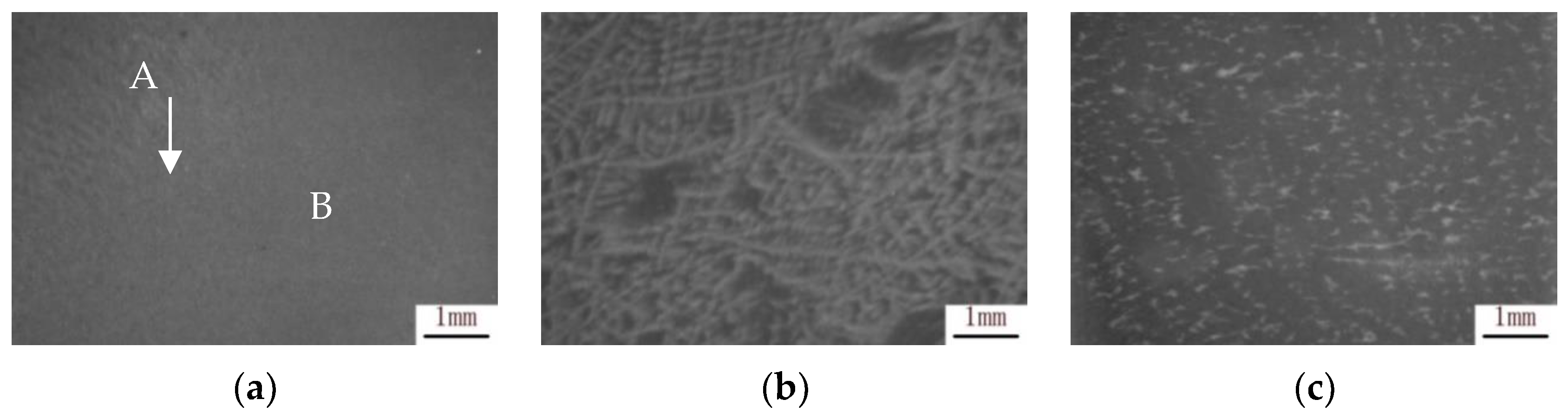
Figure 3.
OM images of microstructure at different positions in steel block: (a) edge; (b,c) 1/4 of diagonal; (d) core.
Figure 3.
OM images of microstructure at different positions in steel block: (a) edge; (b,c) 1/4 of diagonal; (d) core.
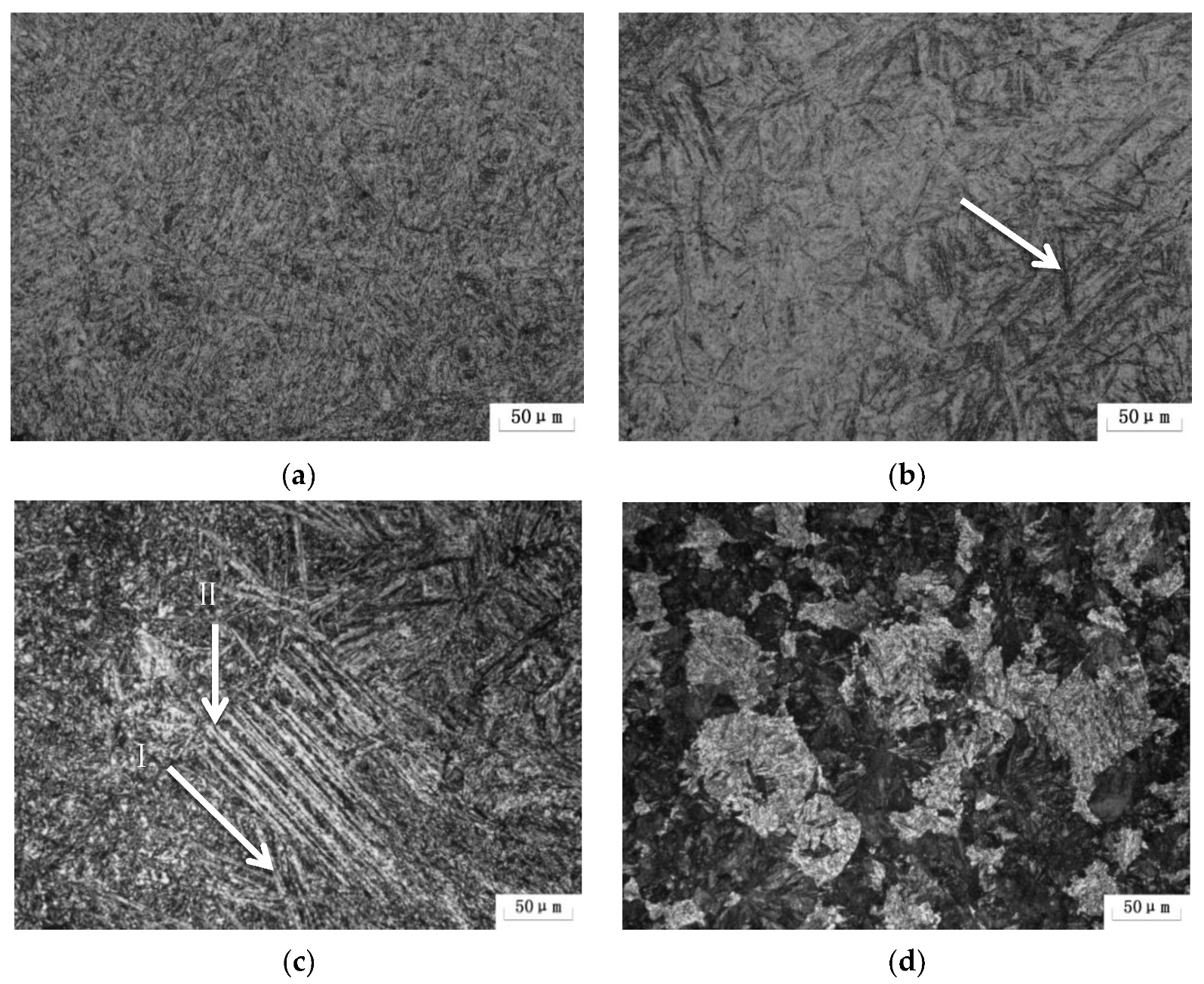
Figure 4.
SEM image of microstructure at different positions in steel block: (a) edge; (b,c) 1/4 of diagonal; (d) core.
Figure 4.
SEM image of microstructure at different positions in steel block: (a) edge; (b,c) 1/4 of diagonal; (d) core.

Figure 5.
TEM images of microstructure at different positions in the steel block: (a) edge; (b,c) 1/4 of diagonal; (d) core.
Figure 5.
TEM images of microstructure at different positions in the steel block: (a) edge; (b,c) 1/4 of diagonal; (d) core.
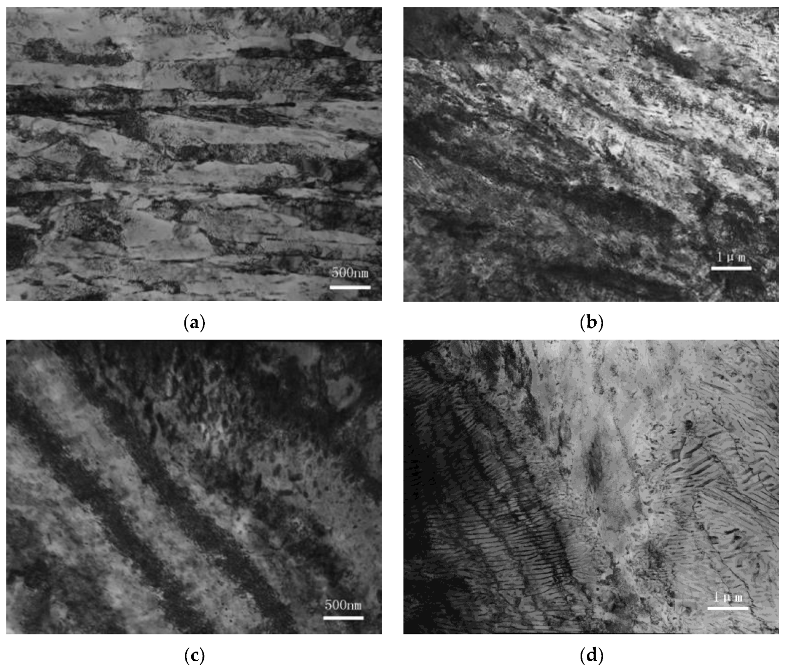
Figure 6.
Microstructure displayed as unique color maps of a 1.2738 steel bloom (IPF map): (a) tempered sorbite; (b) tempered bainite; (c) tempered bainite + pearlite; (d) inverse pole figure for color code.
Figure 6.
Microstructure displayed as unique color maps of a 1.2738 steel bloom (IPF map): (a) tempered sorbite; (b) tempered bainite; (c) tempered bainite + pearlite; (d) inverse pole figure for color code.
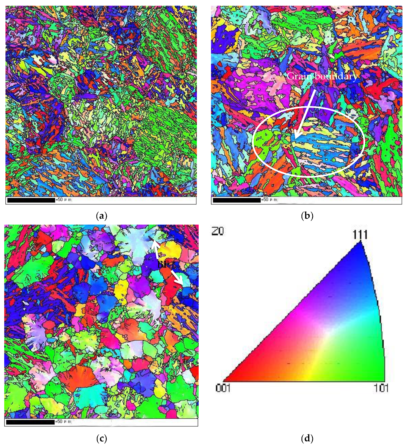
Figure 7.
Hardness distribution across the transverse 1/4 section of a 1.2738 steel bloom.

Figure 8.
Tensile properties at different positions of a 1.2738 steel bloom: (a) tensile strength (UTS) and yield strength (YS); (b) reduction (A) and elongation (Z) of the section.
Figure 8.
Tensile properties at different positions of a 1.2738 steel bloom: (a) tensile strength (UTS) and yield strength (YS); (b) reduction (A) and elongation (Z) of the section.

Figure 9.
Polishing performance characterized using a three-dimensional AFM map of different microstructures (50 × 50 μm): (a) tempered sorbite (edge); (b) tempered bainite (diagonal 1/4 position); (c) pearlite + tempered bainite (core); (d) pearlite (core); (e) sorbite + granular carbide (segregation band position).

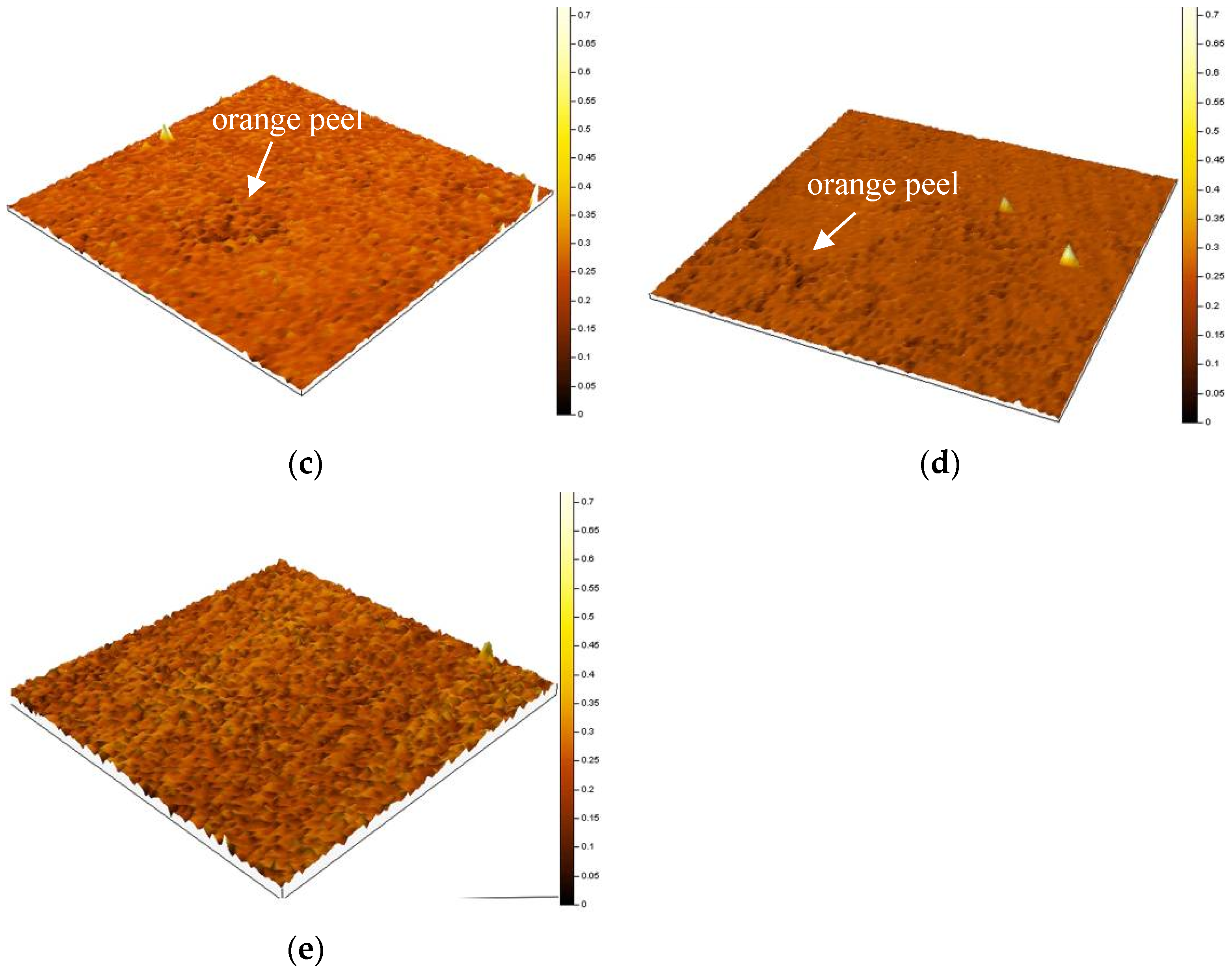
Figure 10.
Partial five-fold-enlarged view of Figure 9: (a) tempered sorbite (edge); (b) tempered bainite (diagonal 1/4 position); (c) pearlite + tempered bainite (core); (d) pearlite (core); (e) sorbite + granular carbide (segregation band position).
Figure 10.
Partial five-fold-enlarged view of Figure 9: (a) tempered sorbite (edge); (b) tempered bainite (diagonal 1/4 position); (c) pearlite + tempered bainite (core); (d) pearlite (core); (e) sorbite + granular carbide (segregation band position).
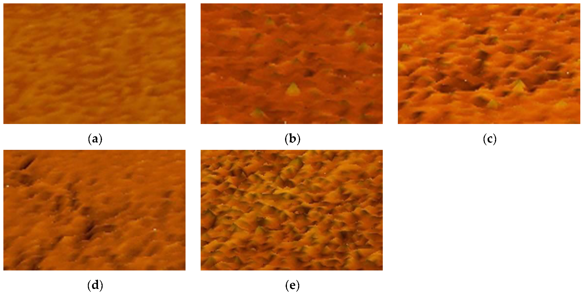
Figure 11.
Calculated CCT (a) and TTT (b) curves for the studied steel.

Table 1.
The chemical composition of 1.2738 steel bloom (wt. %).
| Steel | C | Si | Mn | P | S | Cr | Ni | Mo | Fe |
|---|---|---|---|---|---|---|---|---|---|
| 1.2738 | 0.40 | 0.43 | 1.40 | 0.0081 | 0.0023 | 1.92 | 1.05 | 0.31 | Bal. |
Disclaimer/Publisher’s Note: The statements, opinions and data contained in all publications are solely those of the individual author(s) and contributor(s) and not of MDPI and/or the editor(s). MDPI and/or the editor(s) disclaim responsibility for any injury to people or property resulting from any ideas, methods, instructions or products referred to in the content. |
© 2024 by the authors. Licensee MDPI, Basel, Switzerland. This article is an open access article distributed under the terms and conditions of the Creative Commons Attribution (CC BY) license (https://creativecommons.org/licenses/by/4.0/).
Share and Cite
MDPI and ACS Style
Chi, H.; Liu, J.; Zhou, J.; Ma, D.; Gu, J. Influence of Microstructure on the Mechanical Properties and Polishing Performance of Large Prehardened Plastic Mold Steel Blocks. Metals 2024, 14, 477. https://doi.org/10.3390/met14040477
AMA Style
Chi H, Liu J, Zhou J, Ma D, Gu J. Influence of Microstructure on the Mechanical Properties and Polishing Performance of Large Prehardened Plastic Mold Steel Blocks. Metals. 2024; 14(4):477. https://doi.org/10.3390/met14040477
Chicago/Turabian StyleChi, Hongxiao, Jihao Liu, Jian Zhou, Dangshen Ma, and Jinbo Gu. 2024. "Influence of Microstructure on the Mechanical Properties and Polishing Performance of Large Prehardened Plastic Mold Steel Blocks" Metals 14, no. 4: 477. https://doi.org/10.3390/met14040477
Note that from the first issue of 2016, this journal uses article numbers instead of page numbers. See further details here.