
Effect of Deep Cryogenic Aging Treatment on Microstructure and Mechanical Properties of Selective Laser-Melted AlSi10Mg Alloy

1
Research Institute of Aero-Engine, Beihang University, Beijing 100191, China
2
National Engineering Laboratory of Additive Manufacturing for Large Metallic Components, Beihang University, Beijing 100191, China
3
AECC Beijing Institute of Aeronautical Materials, Beijing 100095, China
*
Author to whom correspondence should be addressed.
Metals 2024, 14(5), 493; https://doi.org/10.3390/met14050493
Submission received: 26 March 2024
/
Revised: 18 April 2024
/
Accepted: 18 April 2024
/
Published: 24 April 2024
(This article belongs to the Special Issue Advances in Laser Metal Deposition Processes)
Abstract
:Deep cryogenic aging (DCA) is a newly developed heat treatment technique for additive-manufactured metallic materials to reduce residual stress and improve their mechanical properties. In this study, AlSi10Mg alloy samples fabricated by selective laser melting were deep-cryogenic-treated at −160 °C and subsequently aged at 160 °C. Phase and microstructural analyses were conducted using X-ray diffraction, optical microscopy, scanning electron microscopy, and transmission electron microscopy, while the mechanical properties were evaluated through microhardness and tensile testing at room temperature. The results indicated that the DCA treatment did not have an effect on the morphology of the melt pools. However, it facilitated the formation of atomic clusters and nanoscale Si and β′ phases, as well as accelerating the coarsening of grains and the ripening of the eutectic Si phase. After DCA treatment, the mass fraction of the Si phase experienced an increase from 4.4% to 7.2%. Concurrently, the volume fraction of the precipitated secondary phases elevated to 5.1%. The microhardness was enhanced to 147 HV, and the ultimate tensile strength and yield strength achieved 495 MPa and 345 MPa, respectively, with an elongation of 7.5%. In comparison to the as-built specimen, the microhardness, ultimate tensile strength, and yield strength increased by 11.4%, 3.1%, and 19.0%, respectively. The improvement in mechanical properties is primarily attributed to the Orowan strengthening mechanism induced by the secondary phases.
1. Introduction
Currently, the AlSi10Mg alloy, produced through additive manufacturing (AM), is extensively utilized in commercial sectors such as the aviation, aerospace, and automotive industries [1,2,3]. It exhibits exceptional adaptability in AM processes and is compatible with primary AM technologies, including selective laser melting (SLM) and directed energy deposition (DED) [4,5]. During the SLM process, AlSi10Mg alloy powders are melted by a high-energy laser beam, leading to rapid solidification at cooling rates of 103~107 K/s [6]. This rapid solidification results in unique microstructural characteristics including ultrafine microstructures and supersaturated solid solutions (SSSs) [7], as well as relatively prominent tensile strengths [8]. However, it is reported that significant residual tensile stress is generated by the thermal cycling during the SLM process [6,9]. Therefore, appropriate post-treatment techniques are usually required to reduce or eliminate the residual stress in order to avoid thermal distortion or undesirable cracking [10,11].
Research suggests that annealing at 300 °C for 2 h effectively reduces residual stress in the AlSi10Mg alloy, but it compromises strength by forming equilibrium phases and coarsening eutectic Si [12,13]. The T6 treatment, involving solutionizing at 550 °C for 2 h and aging at 180 °C for 2 h, nearly eliminates residual stress but also reduces ultimate tensile strength (UTS) to approximately 330 MPa due to the coarsening of the Si phase and the formation of acicular Al-Fe-Si [6]. Direct aging enhances strength via the deposition of nano-Si or metastable precipitates [14,15,16], but it only partially reduces residual stress by about 32% [17]. In conclusion, achieving comprehensive control over mechanical properties and residual stress demands the development of innovative post-treatment techniques beyond stress relief annealing, T6 treatment, or direct aging.
Deep cryogenic (DC) treatment, renowned for its efficacy in releasing residual stress, refining grain structure, and enhancing the dispersion density of dislocations and precipitates, has emerged as an important technique for improving the microstructure and mechanical properties of metallic materials [18,19,20]. For instance, research has demonstrated that subjecting Ti6-Al4-V alloy weld joints to DC treatment at a temperature of −196 °C for a duration of 24 h significantly reduced the residual stress by 31%, concurrently bolstering its strength by 4.3% and elongation by 48% [21]. Furthermore, the application of DC treatments at −196 °C for 120 h on a CoCrFeMnNi high-entropy alloy produced via laser melting deposition yielded a remarkable doubling of both UTS and yield strength (YS), while concurrently inducting compressive residual stress and defects such as dislocations and stacking faults [22]. In the case of SLM AlSi10Mg alloys, it has been documented that DC treatment, maintained at −196 °C for 24 h, can mitigate residual stress by approximately 72.7% [23]. However, it is noteworthy that the microstructure and mechanical properties of the treated alloy remained largely unchanged when compared to the as-built sample [23], suggesting that a solitary DC treatment for SLM AlSi10Mg is predominantly effective in stress reduction rather than significantly enhancing strength.
Given the capacity of DC treatment to intensify the driving force for atomic precipitation in SSS or to introduce high-density defects [18,24], the combination of DC with other thermal treatments, such as aging, presents a promising avenue for exploration. For example, the EN AW 6026 alloy demonstrated enhanced strength and hardness following a combined DC and aging treatment, attributed to the elevated density of peak aging strengthening precipitates [25]. Similarly, the A356 alloy achieved superior mechanical properties through a multistep heat treatment sequence incorporating solid-solution, DC, and aging processes [26]. For AM metallic alloys, it also has been reported that Inconel 718 achieves remarkable tensile strength and ductility through a strategic combination of DC processing, annealing, and aging treatments [24].
Nonetheless, the scholarly community has yet to delve into the implications of deep cryogenic aging (DCA) on the properties of AlSi10Mg alloys fabricated by SLM. As the microstructure and properties in SLM AlSi10Mg alloys have not been improved remarkably by DC treatment, the subsequent influence of DCA on their microstructure and mechanical properties remains an uncharted area of inquiry. Hence, the present study aims to investigate the effects of DCA on the microstructure, microhardness, and tensile strengths of the SLM AlSi10Mg alloy, thereby laying the groundwork for future research endeavors into the enhancement of AM Al alloys through DCA treatment.
2. Materials and Methods
Figure 1a delineates the workflow adopted in this research endeavor. The raw material employed consists of Al-10Si-0.35Mg alloy powders, with particle sizes ranging from 15 μm to 53 μm, which are utilized in the SLM process. The oxygen content within the alloy powders was measured through impulse-heating infrared absorption analysis, while other constituent elements were determined by inductively coupled plasma atomic emission spectrometry. The detailed chemical composition of the powders is presented in Table 1.
SLM fabrication was executed on a BLT-S310 powder-bed machine, equipped with a Yb fiber laser, within an atmosphere of high-purity argon (with a residual oxygen concentration of approximately 0.1%). During the SLM process, the laser power was set at 350 W, and the scanning speed was maintained at 1100 mm/s. The scanning direction was rotated by 67° between each layer, with a layer thickness of 30 μm. For the purpose of tensile testing, rod specimens in the horizontal (X/Y) orientations with a diameter of 15 mm and a length of 80 mm were fabricated, as depicted in Figure 1b.
The experimental schedules for the DC treatment and aging process are shown in Figure 2. During the DC treatment, the as-built samples were cooled at a rate of approximately 20 °C/min to −160 °C, where they were maintained for a duration of 1 h within a specialized apparatus infused with liquid nitrogen. Subsequently, the specimens were allowed to recover to ambient temperature. Finally, the aging process was conducted at a temperature of 160 °C for a period of 6 h for both the as-built and DC-treated samples, followed by air cooling. The status of the specimens and their respective heat treatment procedures are presented in Table 2.
Microstructural samples, with a thickness of 5 mm, were cut from both the AB and heat-treated rods. These samples were meticulously ground and polished using a series of sandpapers and a diamond polishing agent. Keller’s reagent was employed to etch the polished samples for about 20 s. X-ray diffraction (XRD) patterns were acquired for the XZ section within the range of 20° to 80°, utilizing Cu-Kα diffraction (λ = 0.154 nm) with a scanning speed of 4°/min on a D8 ADVANCE X-ray diffractometer. The XRD patterns were analyzed with the Jade 9.0 software. Metallographic structures were observed using the Leica DM 4000 optical microscope. Furthermore, the FEI nano 450 field emission scanning electron microscope (SEM) was utilized to investigate the microstructure and tensile fracture morphologies. For transmission electron microscopy (TEM) observation, specimens were precision-cut using electrical discharge machining to a thickness of approximately 0.5 mm, and then further reduced to a thickness of 30~50 μm by grinding. Ion milling was performed on a Gatan Model 695 PIPS II apparatus, with the specimens cooled using liquid nitrogen. The morphology of the precipitates was examined with the FEI Tecnai G2 F20 TEM at a test voltage of 200 kV, and the TEM morphology images were analyzed using the Gatan DigitalMicrograph 3.11.2 software. The FM-700 microhardness testing apparatus, employing a 25 gf load for a duration of 15 s, was utilized to measure the microhardness in the melt pools of each specimen. Subsequently, the tensile rods were machined into standard circular tensile specimens with a diameter of 5 mm and subjected to tensile testing at ambient temperature conditions utilizing the AG-IS250kN universal material testing machine, according to the Chinese national standard GB/T 228.1-2010 [27].
3. Results
3.1. XRD Analysis
Figure 3 presents the XRD patterns and corresponding analysis for the AB, DA, and DCA samples. Diffraction peaks belonging to the α-Al phase (PDF No. 03-065-2869, RIR = 4.30) and the Si phase (PDF No. 97-002-9287, RIR = 4.87) were detected in each sample. The relative intensities of the Al (111) diffraction peaks were markedly greater than those of the Al (200) peaks, suggesting the development of a crystallographic texture within the α-Al grains along the XZ cross-sectional plane [14]. This textural characteristic was observed to remain treated after the DA and DCA processes. Moreover, the faint diffraction peaks associated with the Si phase suggest a minimal Si content in these samples, as the majority of the alloying elements dissolved into the α-Al matrix [13]. Upon comparing the positions of the Al (311) diffraction peaks for each sample, it was noted that all Al (311) peaks exhibited a shift towards the higher-angle side compared to the standard diffraction peak center, as depicted in Figure 3b. This shift can be attributed to the smaller atomic radius of Si compared to Al and the formation of substitutional solid solutions as Si atoms dissolved into the α-Al matrix, thereby reducing the interplanar spacing within the α-Al structure. In accordance with the Bragg equation () [17], a reduction in interplanar spacing (d) is correlated with an increase in the diffraction peak angle (). Consequently, the shift of diffraction peaks towards the higher-angle side was generated. Furthermore, the XRD analysis revealed that the peak centers of the Al (311) diffraction peaks for the AB, DA, and DCA samples were located at 78.404°, 78.344°, and 78.285°, respectively, which suggest that the AB sample exhibited the highest level of solid solution, followed by the DA sample, with the DCA sample displaying the lowest level. This indicates that the DC treatment enhances the driving force for the precipitation of solid-solution atoms and accelerates the aging precipitation process. Quantitative analysis of the primary diffraction peak intensities (IAl and ISi) was employed to estimate the fractions of α-Al and Si phases, as presented in Table 3. The results indicated that the mass fractions of the Si phase in the AB, DA, and DCA samples were approximately 4.4%, 6.0%, and 7.2%, respectively. This suggests that the precipitation of the Si phase occurred during the DA and DCA processes, with a greater generation of Si phases following the DCA treatment.
The XRD patterns between 25° and 50° are depicted in Figure 3c. A broadening of Si diffraction peaks was observed by comparing with the α-Al diffraction peaks. The full widths at half maximum (FWHMs) of the main diffraction peaks were measured, as illustrated in Figure 3d. The results showed that the FWHMs of the Si diffraction peaks ranged between 0.60° and 0.85°, while the FWHMs of the α-Al diffraction peaks were less than 0.3°. Moreover, the FWHMs of the Si phase exhibited irregular changes, whereas the FWHMs of α-Al in the AB sample were larger than those in the DA and DCA samples. The broadening of the Si diffraction peaks is indicative of the presence of amorphous Si within these samples. It has been reported that the ultrahigh cooling rate during the SLM process leads to the formation of some amorphous Si structures in the AB specimen [28]. The observed broadening of the Si diffraction peaks in the DA and DCA samples suggests that these treatments do not have significant effects on the amorphous Si. The FWHMs of the Al (111) and Al (200) diffraction peaks were simultaneously reduced following the application of DA and DCA treatments, suggesting an increase in the α-Al grain size in accordance with the Scherrer equation [29]. As illustrated in Table 3, the α-Al grains oriented with (111)Al in the AB, DA, and DCA specimens exhibited approximate sizes of 35.7 nm, 88.6 nm, and 81.3 nm, respectively. It is evident that the grains undergo considerable growth following the application of the DA treatment; similar results have been noted in previous studies [17,30]. However, the extent of grain growth is diminished subsequent to the DCA treatment, which indicates that the DC treatment effectively inhibits grain growth during the aging process. Notably, the grain size obtained through XRD in this study is significantly smaller than the values reported in references [17,30]. This discrepancy is likely due to the fact that other studies utilized electron backscatter diffraction (EBSD) to conduct a comprehensive statistical analysis of the size distribution of all oriented grains across a relative larger region, thus providing a more complete dataset. In contrast, only the grain size of (111)Al orientation was estimated in this work. Nonetheless, the truth about grain growth after DA and DCA treatment has been confirmed by XRD.
3.2. Microstructure Revolution
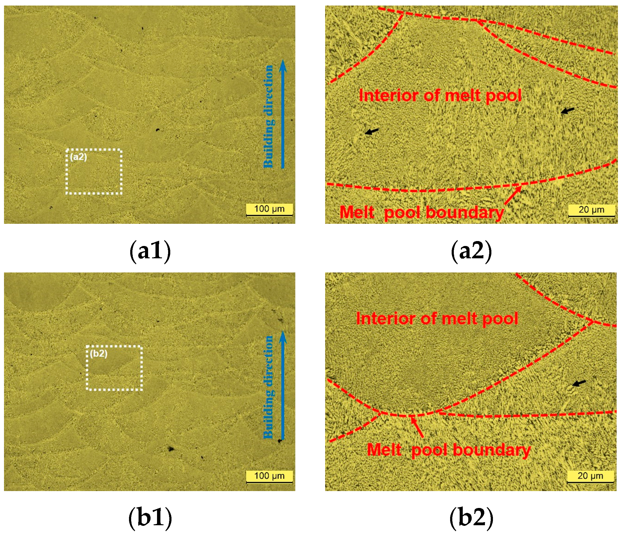
Figure 4 presents the metallographic structures of the various specimens. It is note-worthy that all specimens exhibit a comparable melt pool structure, characterized by a layer-by-layer construction parallel to the building direction. Additionally, the melt pools display a “fish scale” morphology, which can be attributed to the axisymmetric Gaussian power density distribution of the laser beam [10]. The microstructure within the melt pool is relatively homogeneous and fine, with the exception of a few coarse structures (indicated by black arrows in Figure 4). In contrast, the microstructure near the melt pool boundaries is relatively inhomogeneous and coarse.
Figure 5 depicts the SEM morphologies of the AB, DA, and DCA specimens. It can be observed that the microstructural morphologies of these samples are similar, comprising primary Al matrices and cellular eutectic Si networks. Based on the morphology and size of the eutectic Si, three distinct zones can be identified: the coarse cellular zone (CCZ), the fine cellular zone (FCZ), and the heat-affected zone (HAZ), as illustrated in Figure 5(a1,b1,c1). In the CCZ, the widths of the eutectic Si network and the sizes of the network nodes are relatively larger, and noticeable secondary dendritic structures are consistently observed in the cellular eutectic Si, as presented in Figure 5(a2,b2,c2). Conversely, the eutectic Si networks and nodes in the FCZ are significantly finer, with minimal secondary dendritic structures, as shown in Figure 5(a3,b3,c3). The widths of the eutectic Si network and the sizes of the network nodes in the HAZ are comparable to those in the FCZ. However, the connectivity of the eutectic Si network in the HAZ is notably inferior to that in the CCZ and FCZ. It has been established that the primary cause of the formation of the CCZ, FCZ, and HAZ is the distinct thermal histories experienced during the SLM process [31]. For instance, the FCZ is a liquid-phase region where the temperature exceeds the liquidus temperature of the AlSi10Mg alloy, leading to the formation of a fine cellular eutectic structure by rapid solidification. Meanwhile, the CCZ represents a semisolid region formed by reheating the previously solidified structure to a temperature between the solidus and liquidus temperatures, resulting in a relatively coarser eutectic Si network. The HAZ, distinguished by the disconnection of the Si network, is the previously solidified region adjacent to the melt pool boundaries that is heated to a temperature below the solidus line [31].
Additionally, the internal morphologies of the primary Al matrix in the AB and DA specimens are relatively homogenous, with only a few secondary phases observed (as indicated by the black arrows in Figure 5). In contrast, the DCA specimen exhibits a substantially higher number of secondary phases in the primary Al matrix, which manifest as rod-like (or needle-like) and particle-like morphology. The mean diameters and volume fractions of these secondary phases in the AB, DA, and DCA specimens were subjected to statistical analysis, as presented in Figure 6a. It is evident that the volume fraction significantly increases from approximately 0.5% to 5.1% following DCA treatment. Concurrently, the mean diameter expands from around 12.5 μm to 18.7 μm. These results suggest that DCA treatment accelerates the precipitation and growth of various secondary phases. Additionally, a comparative analysis of the morphology of cellular eutectic Si in the FCZ of each state reveals that the eutectic Si networks following DCA treatment exhibit more discontinuities, whereas the eutectic Si in the AB and DA samples tends to form a more continuous network. This indicates that, in contrast to the AB and DA specimens, the connectivity of the cellular eutectic Si network in the DCA sample is notably weaker.
Furthermore, the AB, DA, and DCA samples also display variations in the wall thickness and width of the cellular eutectic Si network. As illustrated in Figure 6b, the statistical analysis suggests that the wall thicknesses and widths of the cellular eutectic Si network in these samples are approximately 0.06 μm and 0.34 μm, 0.06 μm and 0.32 μm, and 0.07 μm and 0.40 μm, respectively. It is observed that the wall thickness and width of the cellular eutectic Si network in the DA state are comparable to those in the AB specimen. However, after DCA treatment, both the wall thickness and width of the cellular eutectic Si network exhibit a slight increase. In summary, the DCA treatment not only promotes the deposition and growth of secondary phases but also accelerates the coarsening and disconnection of the cellular eutectic Si.
The TEM morphologies of the SLM AlSi10Mg alloy in various states are presented in Figure 7. The observations reveal that the microstructures consist of primary α-Al and a cellular structure for the AB, DA, and DCA specimens. However, the internal morphologies of the primary α-Al in these samples are notably distinct. The primary α-Al in the AB specimen appears homogeneous, with no secondary phase present, as illustrated in Figure 7(a1). In the DA and DCA samples, the presence of rod-like and particle-like second phases is observed, as shown by the white arrows in Figure 7(b1,c1). Moreover, the selected area diffraction pattern (SADP) of the primary α-Al in these samples exhibits notable differences. Specifically, the AB specimen features a single set of α-Al diffraction spots, as depicted in Figure 7(a2). In contrast, the SADPs for the DA and DCA samples, shown in Figure 7(b2,c2), reveal additional diffraction spots indicative of other phases alongside the α-Al spots. These observations affirm that the DA or DCA treatments promote the formation of second phases.
Further analysis of the primary α-Al in the AB sample reveals the presence of certain precipitated phases, as indicated by the arrows in Figure 7(a3). These precipitates, approximately 5 nm in size, are observed to be coherent with the α-Al. Additionally, a set of weak diffraction spots is visible in the fast Fourier transform (FFT) pattern of this region, suggesting the presence of GP zones within the primary α-Al of the AB sample [32]. The formation of GP zones in the AB sample can be attributed to the exposure of the solidified structure to heat transfer from subsequent layers, leading to the segregation of dissolved atoms around defects such as vacancies and dislocations. In the DA and DCA specimens, atomic clusters with a size of approximately 1~2 nm are identified within the primary α-Al, as shown by the arrows in Figure 7(b3,c3). These clusters, smaller than the GP zones in the AB sample, do not exhibit diffraction spots in the FFT patterns. The results indicate that the atomic clusters in the DA and DCA specimens represent an earlier intermediate state in the precipitation sequence of SSS→Clusters→GP zones→β″→β′→β [33,34], compared to the GP zones. The segregation of solution atoms during the aging stage is responsible for the formation of atomic clusters.
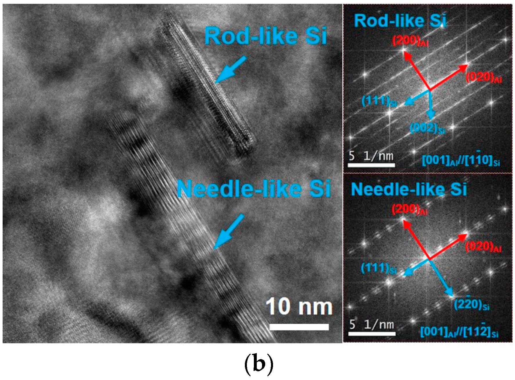
According to Figure 7, the morphologies of precipitations in the DA and DCA specimens are similar, mainly consisting of rod-like (or needle-like) and particle-like phases. Figure 8 displays the TEM morphologies and their corresponding FFT patterns of precipitations. It is evident that the precipitate phases exhibit three types of morphologies: particle-like, rod-like, and needle-like. The identification of each precipitated phase and their orientation relationship with α-Al was determined through their FFT patterns. The particle-like phase, approximately 30~40 nm in size, is identified as β′ phase. It exhibits a semi-coherent relationship with α-Al, with an orientation relationship of [001]Al//[100]β′. Both the rod and needle phases consist of Si and have a width of around 6 nm. However, the length of the rod-like and needle-like phases varies significantly. The length of rod-like Si is approximately 25 nm, while it exceeds 45 nm for the needle-like Si. Moreover, the FFT patterns and orientation relationship with α-Al of the rod-like Si and needle-like Si are clearly distinct. The orientation relationship between α-Al and rod-like Si is [001]Al//Si, while it is [001]Al//Si for α-Al and needle-like Si. Additionally, there are slight differences in shapes and FFT patterns for the needle-like Si phases. For instance, in Figure 8a, the FFT pattern reveals extended diffraction streaks due to the regular stacking of needle-like Si phases along the length direction. Conversely, in Figure 8b, the FFT pattern of the needle-like Si phase displays symmetrical spots on both sides of the diffraction spots due to periodic stacking along the width direction. Similarly, the FFT pattern of the rod-like Si phase also exhibits extended streaks because of stacking along the length direction. It is indicated that the GP zones in the AB sample lead to the formation of β′ phases with a size of 30~40 nm, following the precipitation sequence during DA and DCA treatments. Meanwhile, Si atoms are deposited from the SSS, resulting in the formation of needle-like or rod-like Si phases.
3.3. Room Temperature Mechanical Properties
The microhardness measurements in melt pools of the AB, DA, and DCA samples are presented in Figure 9. The data reveal that the microhardness of the AB specimen is approximately 132 HV. After the DA process, the microhardness is elevated by roughly 6.1%, reaching about 140 HV. Meanwhile, DCA treatment further intensifies the microhardness to 147 HV, marking an increase of 11.4% over the AB sample. These results suggest that the DCA treatment surpasses DA in achieving greater hardness, and the hardening effect induced by the aging process can be augmented through the DC treatment.
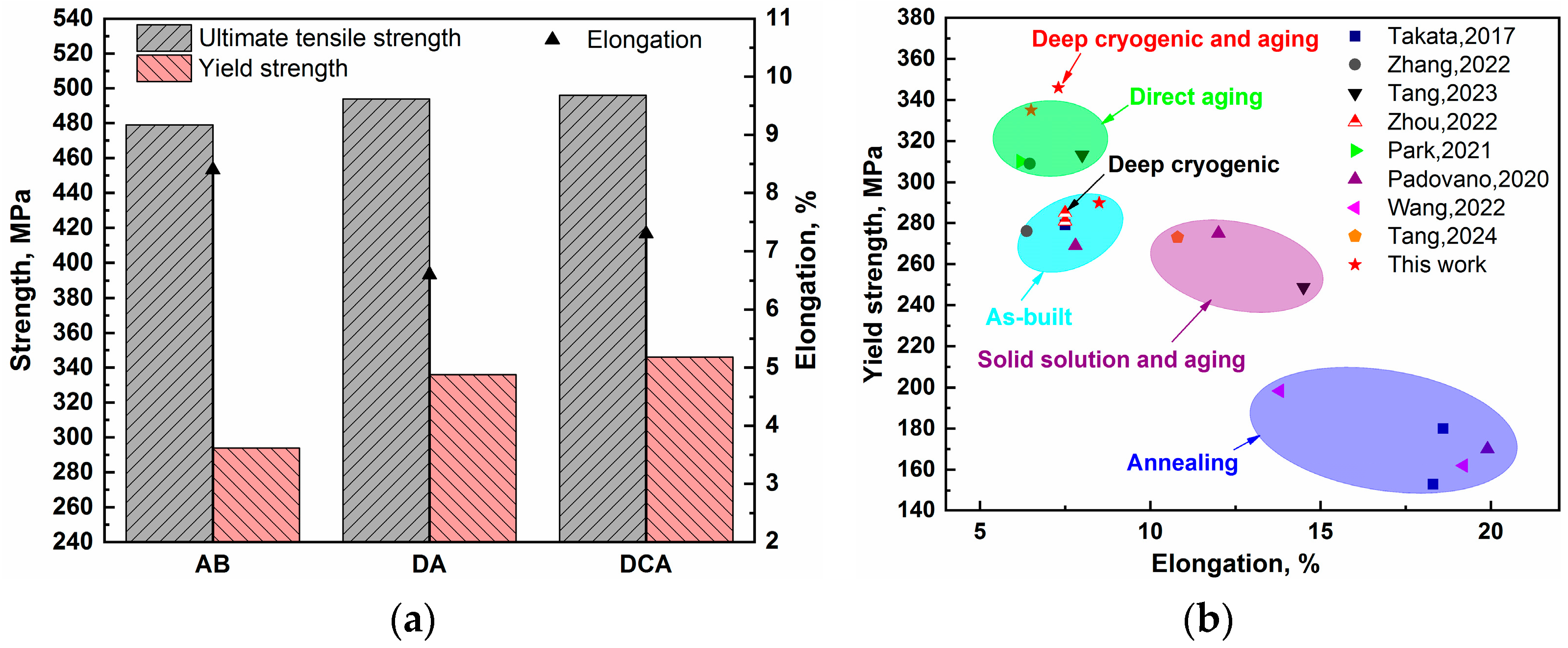
Figure 10 depicts the room temperature tensile properties of the SLM AlSi10Mg alloy. The UTS and YS of the AB sample in the X/Y direction are approximately 480 MPa and 290 MPa, respectively, with an elongation (El) of 8.5%. After DA treatment, the UTS and YS increase to around 495 MPa and 335 MPa, while the El decreases to 6.5%. Through DCA treatment, the UTS and YS are further elevated to about 495 MPa and 345 MPa with the El of 7.5%, which indicates that both the DA and DCA treatments improve the UTS and YS, with the YS demonstrating a more significant increase than the UTS. This can be attributed to the abundant nanoscale precipitates, such as β′ and Si phases, generated after DA and DCA treatments, which hinder dislocation movement, enhance strain hardening capacity, and consequently result in a considerable increase in YS.
In comparison to the YS and El of the SLM AlSi10Mg alloy in the X/Y direction for various states reported in the literature [1,15,17,23,30,35,36,37], as illustrated in Figure 10b, it is noted that the YS of the AB samples is approximately 260–290 MPa, with an El of about 7.5%. After annealing treatment, the El is notably improved, yet the YS decreases to less than 200 MPa. Meanwhile, the YS is comparable to that of the AB samples, while maintaining a good El exceeding 10% after solid-solution and aging treatment. Furthermore, the YS and El do not exhibit significant changes after DC treatment. Although the YS is notably enhanced to over 300 MPa by the DA treatment, the El experiences a slight reduction. In this study, the DCA treatment achieved the highest YS with a substantially equivalent El when compared to the AB and DA samples, indicating that the DCA treatment possesses certain advantages in enhancing the mechanical properties of the SLM AlSi10Mg alloy.
3.4. Fracture Morphology Observation
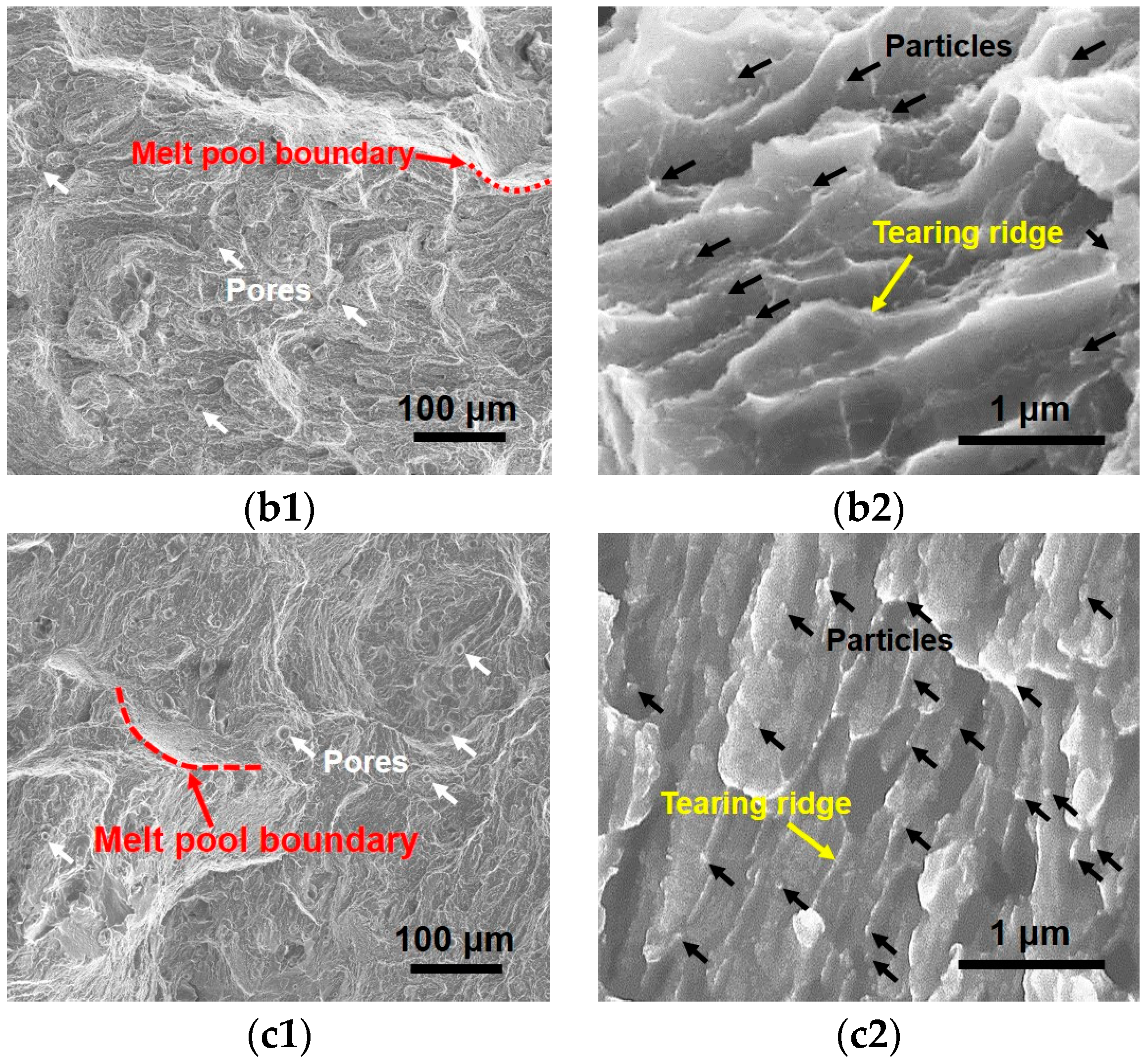
Figure 11 illustrates the fracture morphologies of the AB, DA, and DCA tensile specimens. The results indicate that no clear ductile fracture characteristics were observed. However, stepped cleavage planes, circular pores, and melt pool boundaries were present on the fracture surfaces. These stepped cleavage planes suggest that brittle fracture occurred during crack propagation. The circular pores, indicated by white arrows in Figure 11(a1,b1,c1), are likely to become the preferred path for crack propagation under external loading. Moreover, since the tensile specimens were oriented in the X/Y direction, the cracks primarily propagated in the interiors of the melt pools, with only a small portion extending along the melt pool boundaries.
Upon further examination, it was observed that the fracture surface of the AB specimen exhibited elongated dimples with a width of approximately 0.4 μm. These dimples were relatively shallow, and their edges displayed a characteristic continuous bright net-work, as shown in Figure 11(a2). This suggests that the dimples were formed due to plastic deformation in the primary α-Al under applied external tensile loads. The bright boundaries of the dimples represent the tearing ridges formed after the rupture of the primary α-Al. Moreover, the distinct chain-like distribution of eutectic Si was observed at the bottom of the dimples, as presented by black arrows in Figure 11(a2). According to the microstructural analysis, the plastic deformation of primary α-Al was restricted by the surrounding eutectic Si network, resulting in the formation of relatively shallow dimples. Following DA treatment, the fracture morphology characterized by incomplete, elongated dimples interspersed with discontinuous tearing ridges. Additionally, certain precipitated particles, as denoted by the black arrows in Figure 11(b2), were observed flanking the tearing ridges. For the DCA specimen, the dimple morphology was almost entirely absent, replaced by small cleavage planes. An elevated presence of particles in proximity to the tearing ridges was evident, as illustrated in Figure 11(c2). Summarily, these observations suggest that the reinforcing particles generated through the DA and DCA processes effectively impeded dislocation glide, thereby inhibiting the plastic deformation of primary α-Al and the development of dimples.
4. Discussion
4.1. The Effect of DCA Treatment on Microstructure
The metallographic structure shown in Figure 4 indicates that DCA treatment has no effect on the dimensions, shape, and constitution of the melt pools. This is primarily attributed to the fact that the temperatures employed during the DC and aging stages are substantially lower than those utilized for stress relief annealing and solid-solution treatment. Previous studies have demonstrated that stress relief annealing still maintains the structural characteristics of melt pools, whereas solid-solution treatment brings about discernible alterations [6,12].
Moreover, the DCA treatment is associated with an increased precipitation of atomic clusters and secondary phases, including Si phases and β′ phases. The mass fraction of the Si phase increases from 4.4% to 7.2% after DCA treatment, as presented in Table 3. Concurrently, the volume fraction of Si and β′ precipitates reaches approximately 5.1%.
Furthermore, the DCA specimen exhibits significant grain growth and the ripening of the eutectic Si network, as evidenced in Table 3 and Figure 5, respectively. It is acknowledged that the coarsening of grains and ripening of the eutectic Si are attributed to the aging process. The DC process, on the other hand, plays a distinct role. It effectively inhibits grain growth during subsequent aging, as the degree of grain growth subsequent to DCA treatment is reduced in comparison to that following DA treatment. However, the DC treatment contributes to an increased driving force for atomic diffusion [20,38], leading to the accelerated coarsening and disconnection of the eutectic Si networks during the aging stage. Additionally, the GP zones in the AB sample experience accelerated growth, forming the over-aging strengthening phase β′. Therefore, to refine grain size and optimize the aging strengthening phases, further investigation into optimizing the parameters during DCA treatment is imperative.
4.2. The Effect of DCA Treatment on Properties
After DCA treatment, the microhardness and YS are elevated by approximately 11.4% and 19.0%, respectively. These enhancements in properties are correlated with the alterations in the microstructure. It has been reported that the slipping of dislocations is substantially impeded by the eutectic Si network, SSSs, or precipitates in the SLM AlSi10Mg alloy. Considering the relatively weaker strengthening effect of GP zones or atomic clusters, the YS can be estimated by the following isostrain rule of mixture [39]:
where represents the friction stress, with a value of 10 MPa, while denotes the load bearing of the Si-rich eutectic network at yield point, which is 380 MPa [39]. and are the volume fraction of α-Al cells and the eutectic Si network, with values of 0.88 and 0.12, respectively [39].
It has been reported that the cellular eutectic Si network has a similar obstructive impact on dislocations to grain boundaries, resulting in the accumulation of dislocations along the boundary and the formation of a dislocation wall [39,40]. Hence, the Hall–Petch equation can be applied to estimate the strengthening contribution () produced by the eutectic Si network [39,40]:
where is the Hall–Petch constant specific to Al with the value of 0.04 [39,40]. denotes the width of the cellular eutectic Si network, with respective values of 0.34 μm, 0.32 μm, and 0.40 μm for AB, DA, and DCA specimens.
Furthermore, the following formula is found to be suitable for estimating the solid-solution strengthening effect () in the SLM AlSi10Mg alloy [39]:
where is a constant for the effect of Si in solid solution with a value of 39.7 MPa/wt.%2/3 [39]; represents the concentration of Si atoms in the α-Al matrix. It is clear that the degree of strengthening is directly proportional to the silicon concentration in the matrix. The concentrations, , deduced from the chemical composition of Si (Table 1) and the mass fraction of the Si phase (Table 3), are about 5.6 wt.%, 4.0 wt.%, and 2.8 wt.% for AB, DA, and DCA specimens.
Additionally, dislocations are inclined to bypass secondary phases, such as particle-like β′ phase and rod-like or needle-like Si phase, and to generate dislocation loops around these phases, a phenomenon known as the Orowan mechanism. In this work, the diversities between β′ and Si phases were neglected, and the following equations were employed to determine the Orowan strengthening effects [39]:
where is the Taylor factor with a value of 2; and represent the shear modulus (27 GPa) and the Burgers vector of Al (0.284 nm). is the interparticle spacing within the glide plane, which can be computed using formula (5). and denote the volume fraction and the mean diameter of the precipitates, respectively, as detailed in Figure 6a.
The tabulated data in Table 4 illustrate the values of the experimentally determined YS and the estimated ones through calculation. Notably, the estimated YS is lower than the measurements. This discrepancy is likely attributed to the ignoring of the strengthening contributions from the grain boundaries, GP zones, atomic clusters, and dislocations. Nonetheless, the application of these classic strengthening models allows for the elucidation of the strengthening mechanisms subsequent to the DCA treatment. Specifically, the Orowan strengthening mechanism () contributes significantly to the improvement of strengths, reaching approximately 185.6 MPa for the DCA sample, while it is 83.0 MPa for the AB specimen. It indicates that the Orowan mechanism is the predominant factor in the strength improvement in the DCA-treated material. This conclusion is further corroborated by the abundant precipitates visible in the SEM micrographs and the morphologies of fracture surfaces, as depicted in Figure 5(c3) and Figure 11(c2).
5. Conclusions
The objective of this study was to examine the influence of DCA treatment on the microstructure and mechanical properties of an SLM AlSi10Mg alloy. The comprehensive analysis of the microstructural and property variations in the AB, DA, and DCA specimens yielded the following insights:
- (1)
- DCA treatment accelerates the coarsening of grains and the ripening of cellular eutectic Si, promotes the nucleation of atomic clusters, and facilitates the formation of β′ and nanoscale Si phases. However, it does not significantly alter the morphology or stacking structure of the melt pools in the SLM AlSi10Mg alloy.
- (2)
- The DCA treatment results in an enhancement in the UTS and YS, with increases of approximately 3.1% and 19.0%, respectively, when compared to the AB specimen. Simultaneously, the microhardness is elevated by roughly 11.4%.
- (3)
- The improvement in strength after DCA treatment is predominantly attributed to the Orowan strengthening imparted by the secondary phases.
- (4)
- The emergence of atomic clusters and β′ phases and the pronounced coarsening in grain size suggest that further research is necessary to optimize the processing parameters, including temperature, holding time, and the number of DCA cycles.
Author Contributions
Methodology, P.T. and H.T.; validation, P.T. and Y.W.; formal analysis, T.Y.; resources, Y.W.; data curation, P.T. and T.Y.; writing—original draft preparation, P.T.; writing—review and editing, H.T.; visualization, P.T. and H.T.; project administration, Y.W. All authors have read and agreed to the published version of the manuscript.
Funding
This research was funded by the National Natural Science Foundation of China (52101058) and Aero Engine Corporation of China (ZZCX-2020-020).
Data Availability Statement
The data presented in this study are available in article.
Acknowledgments
The authors would like to thank Kai Han for advice on paraphrasing the manuscript and Xin Fu for assistance in TEM observations. Additionally, we appreciate Junzhou Chen and Peiyong Li for support in terms of resources and form analysis.
Conflicts of Interest
Authors Pengjun Tang, Taiqi Yan, Yu Wu were employed by the company AECC Beijing Institute of Aeronautical Materials. All authors declare that the research was conducted in the absence of any commercial or financial relationships that could be construed as a potential conflict of interest.
References
- Takata, N.; Kodaira, H.; Sekizawa, K.; Suzuki, A.; Kobashi, M. Change in Microstructure of Selectively Laser Melted AlSi10Mg Alloy with Heat Treatments. Mater. Sci. Eng. A 2017, 704, 218–228. [Google Scholar] [CrossRef]
- Blakey-Milner, B.; Gradl, P.; Snedden, G.; Brooks, M.; Pitot, J.; Lopez, E.; Leary, M.; Berto, F.; Du Plessis, A. Metal Additive Manufacturing in Aerospace: A Review. Mater. Des. 2021, 209, 110008. [Google Scholar] [CrossRef]
- Gong, J.; Wei, K.; Liu, M.; Song, W.; Li, X.; Zeng, X. Microstructure and Mechanical Properties of AlSi10Mg Alloy Built by Laser Powder Bed Fusion/Direct Energy Deposition Hybrid Laser Additive Manufacturing. Addit. Manuf. 2022, 59, 103160. [Google Scholar] [CrossRef]
- Li, X.; Yi, D.; Wu, X.; Zhang, J.; Yang, X.; Zhao, Z.; Feng, Y.; Wang, J.; Bai, P.; Liu, B.; et al. Effect of Construction Angles on Microstructure and Mechanical Properties of AlSi10Mg Alloy Fabricated by Selective Laser Melting. J. Alloys Compd. 2021, 881, 160459. [Google Scholar] [CrossRef]
- Shi, S.; Lin, X.; Wang, L.; Wang, Z.; Wei, L.; Yang, H.; Tang, Y.; Huang, W. Investigations of the Processing–Structure–Performance Relationships of an Additively Manufactured AlSi10Mg Alloy via Directed Energy Deposition. J. Alloys Compd. 2023, 944, 169050. [Google Scholar] [CrossRef]
- Fiocchi, J.; Tuissi, A.; Biffi, C.A. Heat Treatment of Aluminium Alloys Produced by Laser Powder Bed Fusion: A Review. Mater. Des. 2021, 204, 109651. [Google Scholar] [CrossRef]
- Alghamdi, F.; Song, X.; Hadadzadeh, A.; Shalchi-Amirkhiz, B.; Mohammadi, M.; Haghshenas, M. Post Heat Treatment of Additive Manufactured AlSi10Mg: On Silicon Morphology, Texture and Small-Scale Properties. Mater. Sci. Eng. A 2020, 783, 139296. [Google Scholar] [CrossRef]
- Zhang, C.; Zhu, H.; Hu, Z.; Zhang, L.; Zeng, X. A Comparative Study on Single-Laser and Multi-Laser Selective Laser Melting AlSi10Mg: Defects, Microstructure and Mechanical Properties. Mater. Sci. Eng. A 2019, 746, 416–423. [Google Scholar] [CrossRef]
- Tabatabaei, N.; Zarei-Hanzaki, A.; Moshiri, A.; Abedi, H.R. The Effect of Heat Treatment on the Room and High Temperature Mechanical Properties of AlSi10Mg Alloy Fabricated by Selective Laser Melting. J. Mater. Res. Technol. 2023, 23, 6039–6053. [Google Scholar] [CrossRef]
- DebRoy, T.; Wei, H.L.; Zuback, J.S.; Mukherjee, T.; Elmer, J.W.; Milewski, J.O.; Beese, A.M.; Wilson-Heid, A.; De, A.; Zhang, W. Additive Manufacturing of Metallic Components—Process, Structure and Properties. Prog. Mater. Sci. 2018, 92, 112–224. [Google Scholar] [CrossRef]
- Chen, H.; Zhang, C.; Jia, D.; Wellmann, D.; Liu, W. Corrosion Behaviors of Selective Laser Melted Aluminum Alloys: A Review. Metals 2020, 10, 102. [Google Scholar] [CrossRef]
- Gite, R.E.; Wakchaure, V.D. A Review on Process Parameters, Microstructure and Mechanical Properties of Additively Manufactured AlSi10Mg Alloy. Mater. Today Proc. 2023, 72, 966–986. [Google Scholar] [CrossRef]
- Limbasiya, N.; Jain, A.; Soni, H.; Wankhede, V.; Krolczyk, G.; Sahlot, P. A Comprehensive Review on the Effect of Process Parameters and Post-Process Treatments on Microstructure and Mechanical Properties of Selective Laser Melting of AlSi10Mg. J. Mater. Res. Technol. 2022, 21, 1141–1176. [Google Scholar] [CrossRef]
- Zhou, L.; Mehta, A.; Schulz, E.; McWilliams, B.; Cho, K.; Sohn, Y. Microstructure, Precipitates and Hardness of Selectively Laser Melted AlSi10Mg Alloy before and after Heat Treatment. Mater. Charact. 2018, 143, 5–17. [Google Scholar] [CrossRef]
- Zhang, H.; Wang, Y.; Wang, J.J.; Ni, D.R.; Wang, D.; Xiao, B.L.; Ma, Z.Y. Achieving Superior Mechanical Properties of Selective Laser Melted AlSi10Mg via Direct Aging Treatment. J. Mater. Sci. Technol. 2022, 108, 226–235. [Google Scholar] [CrossRef]
- Li, D.; Qin, R.; Xu, J.; Chen, B.; Niu, X. Effect of Heat Treatment on AlSi10Mg Lattice Structure Manufactured by Selective Laser Melting: Microstructure Evolution and Compression Properties. Mater. Charact. 2022, 187, 111882. [Google Scholar] [CrossRef]
- Tang, H.; Gao, C.; Zhang, Y.; Zhang, N.; Lei, C.; Bi, Y.; Tang, P.; Rao, J.H. Effects of Direct Aging Treatment on Microstructure, Mechanical Properties and Residual Stress of Selective Laser Melted AlSi10Mg Alloy. J. Mater. Sci. Technol. 2023, 139, 198–209. [Google Scholar] [CrossRef]
- Gao, Q.; Jiang, X.; Sun, H.; Fang, Y.; Mo, D.; Li, X.; Shu, R. Effect Mechanism of Cryogenic Treatment on Ferroalloy and Nonferrous Alloy and Their Weldments: A Review. Mater. Today Commun. 2022, 33, 104830. [Google Scholar] [CrossRef]
- Li, H.; Zhao, W.; Chen, T.; Huang, Y.; Sun, J.; Zhu, P.; Lu, Y.; Ngan, A.H.W.; Wei, D.; Du, Q.; et al. Beneficial Effects of Deep Cryogenic Treatment on Mechanical Properties of Additively Manufactured High Entropy Alloy: Cyclic vs Single Cryogenic Cooling. J. Mater. Sci. Technol. 2022, 115, 40–51. [Google Scholar] [CrossRef]
- Guo, J.; Jin, M.; Su, R.; Li, G.; Qu, Y. Microstructural Morphology and Mechanical Properties of Deep Cryogenic Treatment Modified Al-Cu-Mg-Ag Alloy. Mater. Today Commun. 2024, 38, 107670. [Google Scholar] [CrossRef]
- Xu, L.Y.; Zhu, J.; Jing, H.Y.; Zhao, L.; Lv, X.Q.; Han, Y.D. Effects of Deep Cryogenic Treatment on the Residual Stress and Mechanical Properties of Electron-Beam-Welded Ti–6Al–4V Joints. Mater. Sci. Eng. A 2016, 673, 503–510. [Google Scholar] [CrossRef]
- Li, H.G.; Huang, Y.J.; Zhao, W.J.; Chen, T.; Sun, J.F.; Wei, D.Q.; Du, Q.; Zou, Y.C.; Lu, Y.Z.; Zhu, P.; et al. Overcoming the Strength-Ductility Trade-off in an Additively Manufactured CoCrFeMnNi High Entropy Alloy via Deep Cryogenic Treatment. Addit. Manuf. 2022, 50, 102546. [Google Scholar] [CrossRef]
- Zhou, C.; Sun, Q.; Qian, D.; Liu, J.; Sun, J.; Sun, Z. Effect of Deep Cryogenic Treatment on Mechanical Properties and Residual Stress of AlSi10Mg Alloy Fabricated by Laser Powder Bed Fusion. J. Mater. Process. Technol. 2022, 303, 117543. [Google Scholar] [CrossRef]
- Liu, B.; Xu, J.; Gao, Y.; Hu, Y.; Yang, X.; Ding, Y.; Zhang, D.; Lu, S. Fine Grains with High-Density Annealing Twins and Precipitates Inducing Favorable Strength and Excellent Plasticity in Laser Powder Bed Fusion-Fabricated Inconel 718 via Deep Cryogenic and Heat Treatments. J. Mater. Sci. Technol. 2024, 187, 28–48. [Google Scholar] [CrossRef]
- Jovičević-Klug, M.; Rezar, R.; Jovičević-Klug, P.; Podgornik, B. Influence of Deep Cryogenic Treatment on Natural and Artificial Aging of Al-Mg-Si Alloy EN AW 6026. J. Alloys Compd. 2022, 899, 163323. [Google Scholar] [CrossRef]
- Wang, H.M.; Li, K.; Li, G.R.; Su, W.X.; Chou, S.S.; Wu, T.T.; Fan, X. Microstructure and Properties of Spinning De-formed A356 Alloy Subject to the Solution-DCT-Aging Multiplex Heat Treatment. J. Mater. Res. Technol. 2023, 23, 5520–5533. [Google Scholar] [CrossRef]
- GB/T 228.1-2010; Metallic Materials—Tensile Testing—Part 1: Method of Test at Room Temperature. Standards Press of China: Beijing, China, 2010.
- Chen, K.J.; Hung, F.Y.; Lui, T.S.; Tsai, C.L. Improving the Applicability of Wear-Resistant Al–10Si–0.5 Mg Alloy Obtained through Selective Laser Melting with T6 Treatment in High-Temperature, and High-Wear Environments. J. Mater. Res. Technol. 2020, 9, 9242–9252. [Google Scholar] [CrossRef]
- Gupta, M.K.; Singla, A.K.; Ji, H.; Song, Q.; Liu, Z.; Cai, W.; Mia, M.; Khanna, N.; Krolczyk, G.M. Impact of Layer Rotation on Micro-Structure, Grain Size, Surface Integrity and Mechanical Behaviour of SLM Al-Si-10Mg Alloy. J. Mater. Res. Technol. 2020, 9, 9506–9522. [Google Scholar] [CrossRef]
- Park, T.-H.; Baek, M.-S.; Hyer, H.; Sohn, Y.; Lee, K.-A. Effect of Direct Aging on the Microstructure and Tensile Properties of AlSi10Mg Alloy Manufactured by Selective Laser Melting Process. Mater. Charact. 2021, 176, 111113. [Google Scholar] [CrossRef]
- Zhao, L.; Song, L.; Santos Macías, J.G.; Zhu, Y.; Huang, M.; Simar, A.; Li, Z. Review on the Correlation between Microstructure and Mechanical Performance for Laser Powder Bed Fusion AlSi10Mg. Addit. Manuf. 2022, 56, 102914. [Google Scholar] [CrossRef]
- Fallah, V.; Korinek, A.; Ofori-Opoku, N.; Raeisinia, B.; Gallerneault, M.; Provatas, N.; Esmaeili, S. Atomic-Scale Pathway of Early-Stage Precipitation in Al–Mg–Si Alloys. Acta Mater. 2015, 82, 457–467. [Google Scholar] [CrossRef]
- Andersen, S.J.; Marioara, C.D.; Frøseth, A.; Vissers, R.; Zandbergen, H.W. Crystal Structure of the Orthorhombic U2-Al4Mg4Si4 Precipitate in the Al–Mg–Si Alloy System and Its Relation to the B′ and B″ Phases. Mater. Sci. Eng. A 2005, 390, 127–138. [Google Scholar] [CrossRef]
- Vissers, R.; Van Huis, M.A.; Jansen, J.; Zandbergen, H.W.; Marioara, C.D.; Andersen, S.J. The Crystal Structure of the B′ Phase in Al–Mg–Si Alloys. Acta Mater. 2007, 55, 3815–3823. [Google Scholar] [CrossRef]
- Padovano, E.; Badini, C.; Pantarelli, A.; Gili, F.; D’Aiuto, F. A Comparative Study of the Effects of Thermal Treatments on AlSi10Mg Produced by Laser Powder Bed Fusion. J. Alloys Compd. 2020, 831, 154822. [Google Scholar] [CrossRef]
- Wang, C.G.; Zhu, J.X.; Wang, G.W.; Qin, Y.; Sun, M.Y.; Yang, J.L.; Shen, X.F.; Huang, S.K. Effect of Building Orientation and Heat Treatment on the Anisotropic Tensile Properties of AlSi10Mg Fabricated by Selective Laser Melting. J. Alloys Compd. 2022, 895, 162665. [Google Scholar] [CrossRef]
- Tang, P.J.; Yan, T.Q.; Chen, B.Q.; Guo, S.Q.; Li, P.Y. Effect of Solid Solution Treatment on Microstructure, Tensile properties and Residual Stress of Selective Laser Melted AlSi10Mg Alloy. J. Mater. Eng. 2024, 52, 155–163. [Google Scholar] [CrossRef]
- Yao, E.; Zhang, H.; Ma, K.; Ai, C.; Gao, Q.; Lin, X. Effect of Deep Cryogenic Treatment on Microstructures and Performances of Aluminum Alloys: A Review. J. Mater. Res. Technol. 2023, 26, 3661–3675. [Google Scholar] [CrossRef]
- Santos Macías, J.G.; Douillard, T.; Zhao, L.; Maire, E.; Pyka, G.; Simar, A. Influence on Microstructure, Strength and Ductility of Build Platform Temperature during Laser Powder Bed Fusion of AlSi10Mg. Acta Mater. 2020, 201, 231–243. [Google Scholar] [CrossRef]
- Hadadzadeh, A.; Amirkhiz, B.S.; Mohammadi, M. Contribution of Mg2Si Precipitates to the Strength of Direct Metal Laser Sintered AlSi10Mg. Mater. Sci. Eng. A 2019, 739, 295–300. [Google Scholar] [CrossRef]
Figure 1.
The workflow diagram of this research (a); schematic of SLM samples (b).

Figure 2.
Scheme of heat treatment procedure for DC and aging process.

Figure 3.
The XRD patterns of the AB, DA, and DCA samples: 2θ angular range from 20° to 80° (a), diffraction curves of Al (311) peaks (b), partial patterns between 25° and 50° (c), and FWHM results of main diffraction peaks (d).
Figure 3.
The XRD patterns of the AB, DA, and DCA samples: 2θ angular range from 20° to 80° (a), diffraction curves of Al (311) peaks (b), partial patterns between 25° and 50° (c), and FWHM results of main diffraction peaks (d).

Figure 4.
The metallographic structures at lower (1) and higher (2) magnification for AB (a1,a2), DA (b1,b2), and DCA (c1,c2) specimens.
Figure 4.
The metallographic structures at lower (1) and higher (2) magnification for AB (a1,a2), DA (b1,b2), and DCA (c1,c2) specimens.


Figure 5.
The SEM morphologies of HAZ (1), CCZ (2), and FCZ (3) in AB (a1–a3), DA (b1–b3), and DCA (c1–c3) specimens.
Figure 5.
The SEM morphologies of HAZ (1), CCZ (2), and FCZ (3) in AB (a1–a3), DA (b1–b3), and DCA (c1–c3) specimens.


Figure 6.
Statistical results of mean diameters and volume fraction of second phases (a); wall thickness and width of cellular eutectic Si network (b).
Figure 6.
Statistical results of mean diameters and volume fraction of second phases (a); wall thickness and width of cellular eutectic Si network (b).

Figure 7.
The TEM morphologies of SLM AlSi10Mg alloys in AB (a1–a3), DA (b1–b3), and DCA (c1–c3) states.
Figure 7.
The TEM morphologies of SLM AlSi10Mg alloys in AB (a1–a3), DA (b1–b3), and DCA (c1–c3) states.

Figure 8.
The TEM morphologies and corresponding FFT patterns of secondary phases: (a) particle-like β′ and needle-like Si; (b) needle-like and rod-like Si.
Figure 8.
The TEM morphologies and corresponding FFT patterns of secondary phases: (a) particle-like β′ and needle-like Si; (b) needle-like and rod-like Si.


Figure 9.
The microhardness in melt pools of AB, DA, and DCA samples.

Figure 10.
The room temperature tensile properties of AB, DA, and DCA specimens (a), and the plot of yield strength versus elongation for different statuses of SLM AlSi10Mg [1,15,17,23,30,35,36,37] (b).

Figure 11.
The fracture morphologies at lower (1) and higher (2) magnification for AB (a1,a2), DA (b1,b2), and DCA (c1,c2) tensile samples.
Figure 11.
The fracture morphologies at lower (1) and higher (2) magnification for AB (a1,a2), DA (b1,b2), and DCA (c1,c2) tensile samples.


Table 1.
Chemical composition of AlSi10Mg alloy powders (wt.%).
| Si | Mg | Fe | Cu | Ti | Mn | Zn | O | Al |
|---|---|---|---|---|---|---|---|---|
| 10 | 0.34 | 0.034 | <0.01 | <0.01 | <0.01 | <0.01 | 0.07 | Bal. |
Table 2.
AlSi10Mg specimens and corresponding heat treatment process.
| Specimens | Heat Treatment Process |
|---|---|
| As-built (AB) | none |
| Direct aging (DA) | 160 °C for 6 h |
| Deep cryogenic aging (DCA) | −160 °C for 1 h and 160 °C for 6 h |
Table 3.
The grain sizes of α-Al and fraction of phases in the AB, DA, and DCA specimens.
| Specimens | IAl | ISi | wAl, wt% | wSi, wt% | FWHM of Al (111), ° | Grain Size, nm |
|---|---|---|---|---|---|---|
| AB | 3280.1 | 170.9 | 95.6 | 4.4 | 0.2466 | 35.7 |
| DA | 4244.2 | 309.4 | 94.0 | 6.0 | 0.0993 | 88.6 |
| DCA | 4184.6 | 368.4 | 92.8 | 7.2 | 0.1082 | 81.3 |
Table 4.
Estimated strengthening components of AB, DA, and DCA specimens. The units are in MPa.
| Specimens | Estimated YS | Measured YS | ||||
|---|---|---|---|---|---|---|
| AB | 10 | 68.6 | 78.8 | 83.0 | 257 | 290 |
| DA | 10 | 70.7 | 63.0 | 125.1 | 282 | 335 |
| DCA | 10 | 63.2 | 49.7 | 185.6 | 317 | 345 |
Disclaimer/Publisher’s Note: The statements, opinions and data contained in all publications are solely those of the individual author(s) and contributor(s) and not of MDPI and/or the editor(s). MDPI and/or the editor(s) disclaim responsibility for any injury to people or property resulting from any ideas, methods, instructions or products referred to in the content. |
© 2024 by the authors. Licensee MDPI, Basel, Switzerland. This article is an open access article distributed under the terms and conditions of the Creative Commons Attribution (CC BY) license (https://creativecommons.org/licenses/by/4.0/).
Share and Cite
MDPI and ACS Style
Tang, P.; Yan, T.; Wu, Y.; Tang, H. Effect of Deep Cryogenic Aging Treatment on Microstructure and Mechanical Properties of Selective Laser-Melted AlSi10Mg Alloy. Metals 2024, 14, 493. https://doi.org/10.3390/met14050493
AMA Style
Tang P, Yan T, Wu Y, Tang H. Effect of Deep Cryogenic Aging Treatment on Microstructure and Mechanical Properties of Selective Laser-Melted AlSi10Mg Alloy. Metals. 2024; 14(5):493. https://doi.org/10.3390/met14050493
Chicago/Turabian StyleTang, Pengjun, Taiqi Yan, Yu Wu, and Haibo Tang. 2024. "Effect of Deep Cryogenic Aging Treatment on Microstructure and Mechanical Properties of Selective Laser-Melted AlSi10Mg Alloy" Metals 14, no. 5: 493. https://doi.org/10.3390/met14050493
Note that from the first issue of 2016, this journal uses article numbers instead of page numbers. See further details here.