
Synergistic Effect of Al and Ni on Microstructure Evolutions and Mechanical Properties of Fe-Mn-Al-C Low-Density Steels


College of Materials Science and Engineering, Taiyuan University of Technology, Taiyuan 030024, China
*
Author to whom correspondence should be addressed.
Metals 2024, 14(5), 495; https://doi.org/10.3390/met14050495
Submission received: 8 April 2024
/
Revised: 20 April 2024
/
Accepted: 22 April 2024
/
Published: 24 April 2024
Abstract
:In this study, the synergistic behavior of Ni and Al in two low-density steels (Fe-26Mn-10.2Al-0.98C-0.15V (wt. %) and Fe-29Mn-5Al-1C-12Ni (wt. %)) and their influence on microstructures and mechanical properties were investigated. The chemical composition of κ-carbides and B2 precipitated particles as a function of annealing and aging temperature and the matrix within which they formed were elucidated. The microstructures and deformation mechanisms of both steels were studied based on their strengthening contribution. The Fe-26Mn-10.2Al-0.98C-0.15V steel mainly realized precipitation strengthening through κ-carbides and grain boundary strengthening due to full recrystallization. The strengthening caused by Fe-29Mn-5Al-1C-12Ni steel was mainly due to the presence of the B2 phase in the matrix, which was non-coherent with FCC. This led to the Orowan bypass mechanism, which made precipitation strengthening the main strengthening contribution. The synergistic effect led to the shear or bypass mechanism of both steels when plane dislocation slip occurred. In addition, it also had an influence on the work-hardening capability during plastic deformation. This study provides a promising way to further enhance the yield strength of low-density austenitic steels through the synergistic effect of Ni and Al.
1. Introduction
The aim of the development of light-weight steels with excellent mechanical properties through adjusting the composition is to make cars safer to drive on one hand and to improve the energy efficiency of the automotive industry on the other hand, thereby reducing fuel consumption and reducing the pressure caused by environmental pollution. This has become a top priority for the auto industry. Therefore, light-weight steel with the addition of aluminum is regarded as a powerful alternative to traditional structural steel due to its low density, high strength and excellent ductility [1,2,3]. Generally, light-weight steel contains Mn, Al and C elements, and its composition is roughly 20–30 wt. %, 6–10 wt. % and ~1 wt. %. The Al content greatly affects the density of light-weight steels. Low-density steels can be divided into four types, austenitic steels, austenite-based duplex steels, ferritic steels, and ferrite-based duplex steels, according to the hot-rolled structure [4,5].
After these steels are subjected to heat treatment under appropriate temperatures and time periods, it is likely to lead to the formation of other complex micro/nano-scale precipitation, for instance, κ-carbides ((Fe, Mn)3AlCx), B2 (FeAl), D03 (Fe3Al) brittle intermetallic compounds and β-Mn along grain boundaries [4]. κ-carbide could be readily sheared by slip dislocations, and this restricts its ability to intensify steels. NiAl-type B2 particles are precipitated in the matrix, improving the properties. Uniformly distributed ultrafine intermetallic B2 precipitates are also crucial to improve the strength and ductility of alloys [6,7].
One of the current challenges facing light-weight steels is that they cannot meet the requirements of some products, such as low or no deformation in the process of automotive structural reinforcement. Many studies have proposed measures to improve yield strength to address this problem [8,9]. One of them is to control the size and location of the precipitated phase. It is reported that changing the aging time affects the size and volume fraction of carbides in austenitic steel, and the work-hardening rate decreases with the increase in the size and volume fraction of carbides [10]. In addition, the mechanical properties can also be improved by adjusting the alloying element content. The results of Kim et al. [11] indicated that the addition of Ni elements can promote the formation of the B2 phase and hinder the dislocation movement, which improves the mechanical properties.
Though Fe-Mn-Al-C steels with single-element addition have been studied in the past, the synergistic effects of multiple elements on the work-hardening behavior of alloys have not been technically researched. In this study, the mechanical properties of steel were improved by adjusting the composition of Al and Ni. The deformation mechanism and strengthening mechanism were analyzed from the perspective of microstructure and strengthening contribution. So, a new method to improve the mechanical properties of steel by regulating the proportion of Al and Ni is presented, and the strengthening contribution of the strengthening mechanism is discussed.
2. Experimental Procedure
2.1. Materials Preparation
The steels used in this study had the nominal compositions of Fe-26Mn-10.2Al-0.98C-0.15V (wt. %) and Fe-29Mn-5Al-1C-12Ni (wt. %), which were austenitic-based duplex steels and single-phase austenitic steels (referred to as D and S, respectively). The materials used in this study were provided by TISCO Group. The surveyed compositions of these steels are listed in Table 1. For D, the sample was solution-treated at 1050 °C for 10 min and then water-quenched, and the sheet was further cold-rolled by 80% thickness reduction and recrystallization and annealed at 930 °C for 2 h (denoted as D-R930 hereinafter). The recrystallized material was aged at 500 °C for 5 h (denoted as D-RA500 hereinafter). For S, the as-hot-rolled sheets were subjected to cold rolling with a reduction of 80%. The sheet was then annealed at 850 °C and 1000 °C for 30 min. Test sheets cut from the heat-treated sheet at 1000 °C were aged at 800 °C for 3 h. The specimens annealed at 850 °C are referred to as S-R850 specimens and the specimens aged at 800 °C are referred to as S-RA800 specimens. Figure 1 shows the heat treatment process flow diagram.
2.2. Microstructural Characterization
The microstructures of the steels were characterized by X-ray diffraction (XRD) (Malvern Panalytical, Malvern, UK), transmission electron microscopy (TEM) (FEI, Hillsboro, OR, USA) and scanning electron microscopy (SEM) (PHENOM SCIENTIFIC, Rotterdam, The Netherlands) with an electron backscatter diffraction (EBSD) (JEOL, Tokyo, Japan) probe. XRD scans were detected by using Cu radiation with the scanning angle range of 2θ being 30–120°. After mechanical grinding and polishing, the samples for microstructure detection were corroded with the solution of HNO3 (4%) and ethyl alcohol (96%) and then observed by SEM with an energy-dispersive X-ray spectrometer (EDS) (PHENOM SCIENTIFIC, Rotterdam, The Netherlands).
2.3. Tensile Tests
The specimens that were 12.5 × 3 × 1 mm3 in size were cut along the rolling direction (RD) from the treated rods. Quasi-static tensile tests were carried out by an Instron 5969 universal testing machine (INSTRON, Norwood, MA, USA) with a strain rate of 1 × 10⁻³ s−1. At least three samples were experimented on to ensure the reliability of the data.
3. Results
3.1. Microstructures
The X-ray diffractograms of the investigated materials in different states are given in Figure 2. Both austenite (FCC) diffraction peaks and ferrite (BCC) diffraction peaks existed in these samples. Due to the fact that the precipitated phase is in the nanometer scale, it is difficult to detect precipitates from the XRD pattern.
Figure 3 shows the microstructures and grain sizes of the tested steels by SEM. The D-RA500 steel is mainly characterized by irregular austenite with a tiny amount of annealing twins and some ferrites (Figure 3a), while the D-R930 steel exhibits a considerable amount of ferrites (Figure 3b). Figure 3c indicates that it is in a heterogeneous state, and Figure 3d shows single-phase austenite. However, it can be found that there are precipitates on the matrix surface of both samples. In order to further explore their deformation mechanisms and strengthening contribution, one group was selected for subsequent characterization according to their tensile curves. Figure 3(a1,a2) show the EBSD diagram and grain size distribution for D-RA500, respectively. Combined with the XRD pattern (Figure 2), it can be concluded that the FCC phase fraction and BCC phase fraction are 53.4% and 46.6%, respectively. The FCC phase includes the austenite matrix and carbide.
3.2. Precipitation Behavior
Figure 4 shows the microgram by TEM and selected area electron diffraction (SAED) patterns for the D-RA500 steel. The dual-phase grain boundaries for the D-RA500 steel are visible and there are annealing twins (Figure 4a). As shown in Figure 4b,c, the SAED patterns reveal the co-existence of ferrite and austenite, which are selected according to the zone axis. Some dislocation lines can be recognized inside the austenite region in Figure 4d. For the D-RA500 steel shown in Figure 4e,g, some tiny particles are precipitated in the matrix, and there are some fixed dislocations in the austenite grains. Subsequent analysis demonstrates that two types of diffraction spots exist, the austenite in the matrix (red) and κ-carbide (blue) (Figure 4h), which means that there is nano-sized carbide in the D-RA500 steel. As shown in Figure 4i, κ-carbides are uniformly distributed in the matrix.
Detailed TEM analyses of the microstructure have been conducted, and the results are exhibited in Figure 5. As for the S-R850 samples, the dislocation walls are close to the grain boundaries constituted of some tangly dislocations (Figure 5a). Some twins and stacking faults are formed, and the SAED analysis can provide conclusive evidence (Figure 5b,c). Figure 5d shows that the S-R850 steel has a heterogeneous microstructure, and there is a clear distinction between the recrystallized region and non-recrystallized region. Figure 5e presents the austenitic matrix with a certain amount of precipitates (in bright contrast) for the S-R850 steel. These have been determined to be (Ni, Al)-rich B2 areas in the corresponding EDS maps (Figure 5g). The B2 phase and the austenitic matrix are incoherent.
3.3. Tensile Properties and Deformation Structure
Figure 6 displays the engineering stress–strain curves of the two experimental steels and the corresponding work-hardening rates, and the mechanical properties are shown in Table 2. For the D-R930 steel, it has a yield strength of ∼680 MPa, an ultimate tensile strength of ∼940 MPa and a total elongation of ∼39% (Figure 6a). After aging at 500 °C for the D-RA500 steel, the yield strength increases to ∼875 MPa, and the ultimate tensile strength of the steel is ∼1035 MPa. But its ductility becomes worse than the D-R930 steel (total elongation of ∼21% vs. 39%). The yield strength and ultimate tensile strength for the S-R850 steel are 865 MPa and 1150 MPa, respectively, while they are 630 MPa and 1065 MPa for the S-RA800 steel, respectively, which are 235 MPa and 85 MPa lower than those. The total elongation of the S-R850 steel (27%) is shorter than that of the S-RA800 steel (36%). Figure 6b shows the work-hardening rate and true stress–strain curves of the experimented steels. At the beginning, the work-hardening rate decreases at a very fast rate, gradually reaches a peak with the increase in strain, and then decreases until the occurrence of fracture (Figure 6b). Interestingly, it is found that the yield strength, tensile strength and tensile ductility of the D-RA500 steel and the S-R850 steel are roughly the same, and they are further analyzed in combination with corresponding microstructures.
The fracture surfaces for the D-RA500 and the S-R850 samples after tensile tests are summarized in Figure 6, which are detected by SEM. For the D-RA500 steel, it presents a mixed mode of inter-granular and cleavage fracture. For the S-R850 steel, it can be found that there are a large number of dimples on the fracture surface, so it can be known that the fracture mode of the sample is mainly ductile fracture.
To reveal the microstructures and deformation mechanisms of the D-RA500 steel, TEM analysis was employed, as shown in Figure 7. Figure 7a displays the slip marks of dislocations. The plastic deformation is mainly dominated by dislocations, and it shows apparent planar slip features, that is, the dislocation is arranged in two directions. The plane slip bands from different slip systems cross randomly, with a Taylor lattice texture arising with a space of several hundred nanometers (Figure 7b). The network structures are thinned with straining, which is the primary cause for outstanding work hardening. With the increase in strain, many new slip bands are active and the slip band spacing becomes smaller, resulting in the slip bands’ refinement, which can inhibit high strain in local areas. This can avert the occurrence of highly local straining in the slip zone, which leads to crack generation and premature failure. The planar slip feature disappears and is displaced by many dislocation tangles (Figure 7c). Figure 7d indicates the bright-field (BF) graph of the sample, and some annealed twins can be seen in Figure 7e.
The deformation structures of the S-R850 steel are surveyed by TEM (along a zone axis) and the experimental findings are presented in Figure 8. As shown in Figure 8a, the dislocations have a random distribution in the austenitic matrix for the tested sample. Meanwhile, when the plastic deformation is large, highly local straining takes place, resulting in the dislocation plugging. As a result, high dislocation density walls (HDDWs) and Taylor lattices (Figure 8a,b) form. These dislocation structures have obvious plane slips [12]. HDDWs are characterized by high dislocation activity and a dense array of parallel dislocations. The selected area diffraction patterns (SADPs) of the S-R850 specimen reveal the presence of austenite grains, as shown in Figure 8c. The presence of microbands in locations with significant strain, as depicted in Figure 8d, is indicative of the occurrence of planar glide. Meanwhile, the deformation twins appear in the S-R850 sample, and their morphology is very different from that of annealing twins. The B2 phase in the sample hinders the movement of the slip bands to some extent, resulting in multiple crosses of the slip bands near B2, and thus, dislocation blockage (Figure 8f). In order to further explore the precipitated particles in Figure 8g, high-resolution TEM (HR-TEM) is used, combined with the corresponding fast Fourier transform (FFT). The consequences are exhibited in Figure 8h. Furthermore, in Figure 8i for the graph of precipitation, the interplanar spacing for the signed B2 particle is approximately 0.241 nm. As obviously shown in Figure 8g, the B2 particles precipitated in the S-R850 steel are widespread, and most of them are approximately elliptical or circular. Annular dark-field (ADF) STEM analysis (Figure 8j) further demonstrates the precipitation of B2 phases in the S-R850 steel. For the S-R850 steel, STEM-EDS mapping images indicate that the B2 nano-particles are enriched in Ni and Al elements but poor in Fe and Mn elements (Figure 8k) [13].
4. Discussion
4.1. Stacking Fault Energy of Both Steels
In steels, the plastic deformation mechanism for the austenite (γ) is decided by the stacking fault energy (SFE) [14]. The content of Fe-Mn-Al-C steel has a great influence on its SFE value, particularly the Al content [1,15,16]. The following equations are generally used for the SFE value of austenitic steels [15,17]:
where is the molar surface density along the (111) planes; is the Gibbs free energy of phase transformation from γ to ε; is the energy of the γ/ε interface, which is 10 J m−2 [17]; is a parameter indicating the impact of grain size on SFE; is the lattice parameter of the material; is Avogatro’s number, where, here, it is 6.2 × 10⁻²³; and are the molar fractions of the pure i and j alloying elements; is the value of free energy from the FCC to HCP structure of the alloying element; is the energy of the interaction in two components; is the Gibbs energy of the magnetic condition.
According to the corresponding grain size and the method of empirical estimation of SFE based on the chemical composition of the steels [17,18,19], the SFE of both steels can be obtained as 77 and 73 , respectively. The SFE value of the full austenitic steel-like type 310 steel ranges from 34 to 80 [20,21]. The difference in SFE in both steels is only 4 . Therefore, it can be concluded that the synergistic effect of Al and Ni in a certain range has little effect on SFE, and the SFE value and the existence of an internal precipitated phase make it mainly show plane slip characteristics during plastic deformation.
4.2. Microstructural Evolution
κ-carbides are one of the most common precipitated phases in light-weight steels [22,23]. Al promotes the formation of ferrite [24], while Mn and C stabilize the austenite region [25]. Due to the formation of κ-carbides, the elements are redistributed during heat treatment [26]. Previous studies [1] have revealed that due to the formation of κ-carbides, the alloying elements of Al, Mn and C migrate from nearby austenite and ferrite regions into the κ-carbides.
When the content of C and Mn is fixed, the critical value of Al content of low-density light-weight steels can be counted by using the following formula if κ-carbide is to be formed [4]:
where , and are the mass fractions of the corresponding elements, respectively. It is found that the content of Al in D-RA500 steel (Table 1) is obviously higher than the calculated critical value of (6.69 wt. %), which indicates that κ-carbides can be precipitated. In contrast, the Al content of the S-R850 steel is below the critical value of , so no κ-carbide precipitates. In addition, if in the material is below the critical lattice constant of the austenite (0.3670 nm), it is difficult to find the formation of κ-carbides in the alloy [4]. For the tested materials, can be calculated using the corresponding parameters measured by XRD and combined with the following equation [27]:
where is the angle of diffraction; is the wavelength of the X-ray (0.154 nm); and h, k and l are parameters of the austenite-dependent surfaces. According to Equation (6), the lattice parameters of both steels can be obtained to determine whether they are conducive to the formation and growth of κ-carbides. The lattice constant of D-RA500 steel is 0.3747 nm, and the lattice constant of S-R850 steel is 0.3132 nm. By comparing these values with the critical value, it can be preliminarily concluded that there is no κ-carbide in S-R850 steel, and κ-carbide exists in D-RA500 steel. This result is also consistent with the microstructure observed by TEM characterization. Therefore, the value in lattice parameters could be one of the reasons for the formation of κ-carbides in the D-RA500 and the S-R850 steels. The κ-carbides precipitated along the grain boundary and the ferrite of the matrix have a pinning effect, which has a certain resistance to the growth of austenite grains.
Twinning usually has an influence on the structures and mechanical properties of light-weight steels [14]. At a low annealing temperature, annealing twins cannot be formed due to insufficient growth kinetics, and after increasing the annealing temperature, some twins appear in both steels (Figure 7d and Figure 8e). Meanwhile, the κ-carbides precipitate at the twin boundary and the twin telos, which hinders the deformation and growth of the twin [28].
The most notable microstructural characteristic of the treated S-R850 steel is a large number of nanoscale B2 precipitated phases in the matrix, which can be seen from Figure 3c. In previous studies, it has been found that after the annealing of Ni-containing steels, the microstructure of the plate-shaped B2 particles could be formed, the size was large (~10 μm) and the distribution was homogeneous [29,30]. It is found that most of the B2 particles are elliptical or circular (size: ~0.13 μm) in the S-R850 steel (Figure 3c and Figure 5e), because the B2 phase is formed in the austenite matrix during annealing, which consumes the content of Ni and Al in the austenite and inhibits the coarsening of B2 in other regions of the matrix [31].
By means of characterization, it can be seen that the microstructure of steel contains a lot of B2 phases precipitated in the austenite, which could be obtained by annealing and water quenching. Compared with other light-weight steels, this microstructure, which combines a soft matrix and a hard second phase, has better mechanical properties, as shown in Figure 9b. In addition, it is found that the results of this paper are not consistent with the results of Kies et al. [13], pointing out that when the content of the B2 phase reaches a constant value of 6.8 vol. %, the ductility will be significantly reduced. So, it is necessary to reduce the B2 content as much as possible. Compared with previously studied steels, S-R850 steel has higher content (22.8% vs. 6.8%), but its ductility is more excellent. This indicates that the deterioration effects caused by the content of the B2 phase can be avoided by regulating the form of the B2 phase, and better performance can be obtained.
Because of the small size of the B2 phase, XRD detection is limited. When detecting the B2 phase, it is found that the corresponding peak broadening range is very large. As a result, the B2 phase peak appears shallow in the diffraction pattern (see Figure 2), which results in weak superlattice reflection and considerable peak overlap. The incoherent B2 phase is formed. It is obvious the B2 precipitated phase is unable to be sheared by the dislocations of plane slip (Figure 8f). According to Refs. [11,32,33], B2 particles and FCC phase have an incoherent relationship, that is, a non-coherent interface is formed. When dislocations move, the B2 phase particles cannot be cut, and the dislocation ring is formed, resulting in dispersion strengthening, and the back stress will be induced on the subsequent dislocation motion, resulting in higher flow stress, that is, the Orowan bypassing mechanism. Then, Orowan loops and corresponding strain gradients appear near precipitations. The loops are known as geometrically necessary dislocations (GNDs) and improve the work-hardening capacity of the material in two ways [34]. Firstly, they associate with slip bands during motion and hinder the movement of dislocations. Secondly, they will create a certain back stress on the dislocation, preventing further slip of the dislocations. This back stress delays dislocation slip, thus consuming more dislocation sources [35]. As a result, the slip plane associated with non-shearable precipitations would be quickly grown and equilibrated with gliding dislocations. To meet the further increase in strain, the number of slip bands increases. This means that the distance between slip bands narrows, and the work-hardening ability is improved. This is consistent with the tested results. It can be seen from Figure 8b that the glide bands are obviously refined compared with Figure 8a. The S-R850 steel shows a better strain-hardening capability than other light-weight steels, as seen from Figure 6b. The strain-hardening capability for the S-R850 steel is due to B2 phase precipitates in the matrix, which causes an Orowan bypassing mechanism [34] and the production of back-stress hardening.
It can be obtained from Figure 7 and Figure 8 that the D-RA500 and the S-R850 steels exhibit typical plane slip after plastic deformation, including unidirectional slip planes and the formation of Taylor lattices at low strain and microstrips at high strain [15]. As shown in Figure 8d, the development of microbands can be clearly veined. A microband is actually a structure composed of GND, and it will eventually increase the total dislocation density, thereby increasing the strength [36]. The source of these GNDs is precisely ascribed to the unsheared ability of the B2 phase, leading to the Orowan bypass mechanism. This results in a dislocation ring, which is intrinsically GND.
4.3. Strengthening Mechanisms
Compared with S-R850 steel, the YS of D-RA500 steel is only increased by ~10 MPa, but the composition of both steels is very different, especially the content of Al and Ni. This means that the synergistic addition of Ni and Al will have different effects on its deformation mechanisms. In general, YS can be showed as the following five parts [12,37]:
where is the lattice friction stress (97 MPa) [38]; is solid solution strengthening; is refined grain strengthening; is dislocation strengthening; is precipitation strengthening [14]. The solution strengthening in both tested steels could be determined by the following formula [2,12]:
where , , , and represent the mass fraction of the corresponding element, respectively. The calculated values for the D-RA500 and the S-R850 steels are 443.9 MPa and 372.8 MPa, respectively. Moreover, according to the classic Hall–Petch relationship, the grain refinement strengthening () [1] is
where is the Hall–Petch coefficient for FCC (485 ) [38] and BCC (570 ) [39]; is grain size (D-RA500: 5.2 μm (austenite); 4.8 μm (ferrite)). The calculated result of the D-RA500 steels is 209.7 MPa. The value could be calculated according to the following formula [40]:
where M is the Taylor factor, which is 3.06; α is a parameter related to the type of material (0.2); b is the Burgers vector (0.26 nm); G is shear modulus (72 GPa) [41]; is the value of dislocation density calculated by XRD. The half-peak width in the XRD pattern, micro-strain ε and grain size d satisfy the W-H (Williamson–Hall) relationship as follows:
where and are the half width and diffraction angle related to the diffraction peak (hkl). Since the grain size for both steels is close to 7 μm, Equation (12) can be changed to the following:
or
The relation for ε and is shown as follows:
where is the lattice parameter of the austenite (nm), and is precipitation strengthening. The value of could be measured by combining the following equation and the experimental data [42] as follows:
where f is the phase fraction of the particles and X is the corresponding average diameter.
The unshearable phase, also known as the hard phase, obstructs the glide of the dislocations and combines the Orowan mechanism to achieve increasing strength [43]. Previous studies have indicated that the presence of shearable phases both within and at grain boundaries can increase the yield strength of the material based on the Orowan mechanisms [44]. Thus, to determine the precipitation-strengthening value in Equation (17), we calculated the average size (X = 0.13 μm) and phase fraction (f = 22.78%) of precipitations for the S-R850 steel through image analysis software (Image-Pro Plus, version 6.0). By Equation (17), the calculation value of precipitation strengthening for the S-R850 steel is 212.4 MPa.
Similarly, we can calculate the precipitation strengthening of the D-RA500 steel according to the following formula [6,45]:
where is the Taylor factor (for FCC: 3.06), b = 0.26 nm is the Burgers vector for the dislocation, is the shear modulus taken to be 70 GPa, w is a dimensionless value equal to 1, is the average particle radius and is the phase fraction of particles. is the number of pile-up dislocations ahead of a κ-carbide ranging from 4 to 8 (here, N = 8). is the anti-phase boundary energy; it changes as the content of carbon in the κ-carbides changes from 0 to 20 and has a range from 350 to 850 (here, = 350 ). According to Equation (18), the calculation value of precipitation strengthening of the D-RA500 steel is 143.7 MPa.
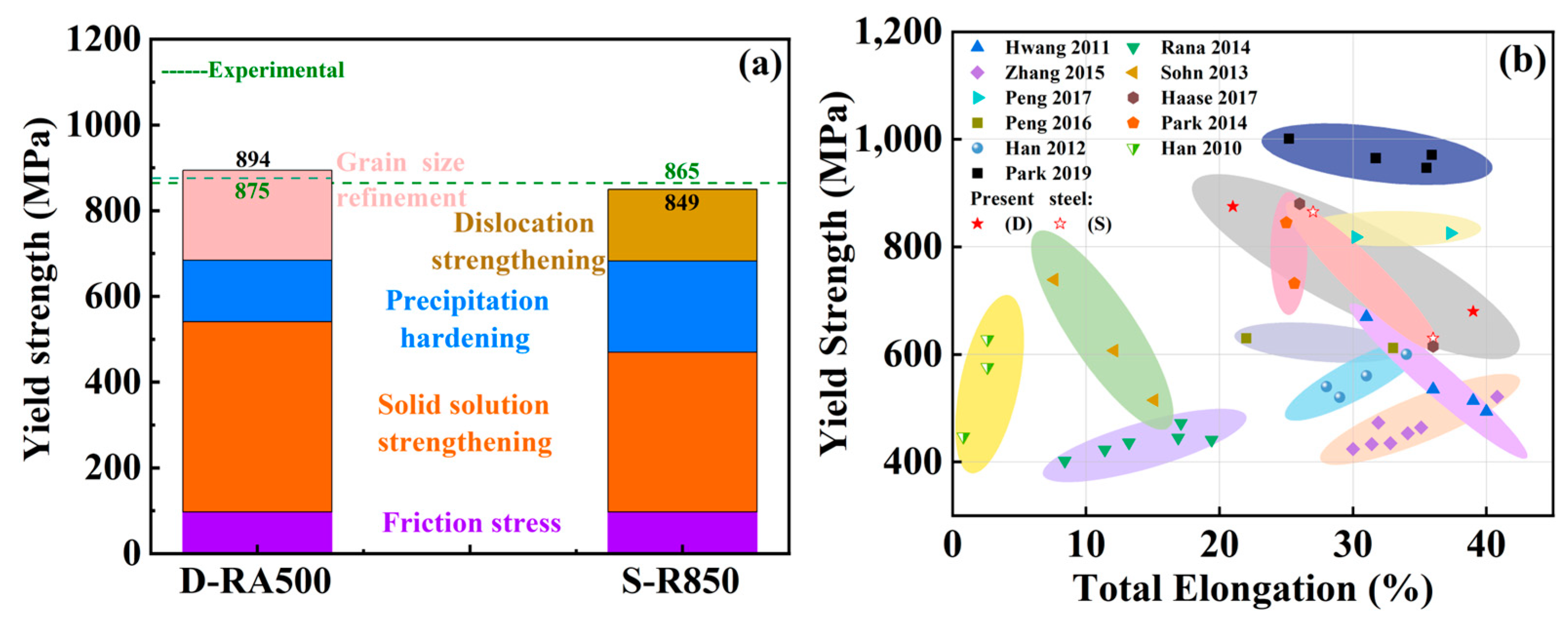
The estimated values of the YS are in good agreement with the experimental ones in Figure 9a. The specific values of the strengthening contribution for the experimental steels are shown in Table 3. The greatest contribution to the total yield strength of the D-RA500 steel is grain refinement and precipitation strengthening. In addition, the strengthening contribution of the S-R850 steel mainly comes from dislocation strengthening and precipitation strengthening. On the one hand, the difference in the strengthening contribution of both steels lies in the type and size of the precipitated phase, and the increase in the dislocation density is related to the precipitation of nanoscale particles. On the other hand, the state of both steels after heat treatment is different, the D-RA500 steel is completely recrystallized, but the S-R850 steel is in a heterogeneous state. In general, during heat treatment and subsequent treatment, the dislocation resulting from the volume change is pinned by the precipitated phase, causing the dislocation density to change.
Figure 9b represents the correlation between yield strength and elongation of the measured specimen. The corresponding data of other low-density steels with similar compositions are also counted in the graph [38,46,47,48,49,50,51,52,53,54,55]. Compared with other alloy materials in the graph, the samples in this paper have better mechanical properties. Among them, the D-RA500 steel can present good TEL as high as 21%, while the S-R850 steel with more Ni has high YS as well as good ductility. The UTS, YS and TEL for the D-RA500 steel are 1035 MPa, 875 MPa and 21%, respectively, while they are 1150 MPa, 865 MPa and 27%, respectively, for the S-R850 steel. This offers a method to solve the problem that high strength and good ductility are unable to coexist in light-weight steels and also supplies a new idea to further improve the yield strength of light-weight steels by adjusting the content of alloying elements.
Figure 9.
(a) Contributions of different strengthening mechanisms to the YS of the experimental steels; (b) variations in yield strength and total elongation of the tested steels and similar types of low-density steels in the literature [38,46,47,48,49,50,51,52,53,54,55].

On the basis of the above results, the development and evolution of microstructures in both steels are illustrated schematically in Figure 10. For the D-RA500 steel, after solution treatment, the microstructure is composed of austenite, ferrite and κ-carbide. In addition, there is a small number of twins (Figure 3a). There are some annealing twins after annealing, which can help to reduce the grain size, but the κ-carbide will hinder the movement of the grain boundary, thus inhibiting the formation of annealing twins, so the twin density is low [56]. In addition, there are nanoscale-ordered carbides in the D-RA500 sample. During plane slip, the dominant dislocation could shear the ordered phase (κ-carbide) and promote the dislocation to continue to expand along the same slip plane, thus promoting plane slip [28]. Secondly, the size of the κ-carbide is small, so a large amount of slip is required to adapt to large plastic deformation, resulting in obvious plane slip [57]. For the S-R850 steel, after cold rolling, a large number of slip bands and high-density dislocations will be produced inside, which would lead to a certain recrystallization driving force for deformed austenite and the B2 phase during high-temperature annealing, causing partial recrystallization. When the crystallization process is carried out, the B2 phase will precipitate at the austenite grain boundary (green triangle in Figure 10) [11,58]. At the same time, B2 particles will also have a pinning effect, hindering the growth of austenite grains. In the incomplete recrystallized region, the B2 phase precipitates along the slip band and dislocation, which will hinder the recrystallization, meaning that the unrecrystallized austenite region accounts for a large part.
5. Conclusions
In summary, this work explored the synergistic effect of Ni and Al on the strengthening contribution and microstructure evolution of low-density steels, and the conclusions are shown below.
By calculating the SFE of the D-RA500 and the S-R850 samples, it can be concluded that the deformation mechanisms are mainly dominated by plane dislocation slip. For the D-RA500 sample, although κ-carbide is present, it belongs to the nanoscale and it is coherent with the matrix, the barrier to dislocation movement is weak. When the dislocations interact and shear the κ-carbides, plane sliding is promoted. For the S-R850 sample, in the incomplete recrystallization state, there is the precipitation of the B2 phase, which will hinder the movement of the dislocation and cause it to produce congestion.
During the plastic deformation process, plane dislocation slip plays a dominant role and causes obvious strain hardening in the steels. The D-RA500 steel has κ-carbides, which are easily sheared by sliding dislocation and result in a low strain-hardening rate, while the S-R850 steel has a B2 phase, which is in a non-uniform relationship with the matrix and will not be sheared by sliding dislocation, so its strain-hardening rate is high.
The yield strength of D-RA500 and S-R850 is similar, but the strength contribution is different. The D-RA500 steel is mainly strengthened by κ-carbide precipitation and grain boundary strengthening under the recrystallization state, while the S-R850 steel is strengthened by dislocation strengthening and B2-phase precipitation in the state of incomplete recrystallization.
Author Contributions
Conceptualization, X.L.; methodology, X.L.; software, X.W.; validation, X.L.; formal analysis, A.L.; investigation, X.L.; data curation, X.L.; writing—original draft preparation, X.L.; writing—review and editing, J.Q.; visualization, A.L.; project administration, J.Q.; funding acquisition, J.Q. All authors have read and agreed to the published version of the manuscript.
Funding
The work was supported by the Natural Science Foundation of Shanxi Province, China (Nos. 20210302124043 and 202203021221083), the Taiyuan Key Core Technology Tackling Project and the Key Research and Development Program of Shanxi Province (No. 202102050201008).
Data Availability Statement
The original contributions presented in the study are included in the article, further inquiries can be directed to the corresponding author.
Acknowledgments
This paper was realized with the help of Yixing Liu, Jinbo Shen and Wenyang Zhang in resources and supervision.
Conflicts of Interest
The authors declare no conflicts of interest.
References
- Xie, Z.; Hui, W.; Zhang, Y.; Zhao, X. Effect of Cu and solid solution temperature on microstructure and mechanical properties of Fe-Mn-Al-C low-density steels. J. Mater. Res. Technol. 2022, 18, 1307–1321. [Google Scholar] [CrossRef]
- Hwang, J.H.; Trang, T.T.T.; Lee, O.; Park, G.; Zargaran, A.; Kim, N.J. Improvement of strength—Ductility balance of B2-strengthened lightweight steel. Acta Mater. 2020, 191, 1–12. [Google Scholar] [CrossRef]
- Zhang, G.F.; Shi, H.Y.; Wang, S.T.; Tang, Y.H.; Zhang, X.Y.; Jing, Q.; Liu, R.P. Ultrahigh strength and high ductility lightweight steel achieved by dual nanoprecipitate strengthening and dynamic slip refinement. Mater. Lett. 2023, 330, 133366. [Google Scholar] [CrossRef]
- Chen, S.; Rana, R.; Haldar, A.; Ray, R.K. Current state of Fe-Mn-Al-C low density steels. Prog. Mater. Sci. 2017, 89, 345–391. [Google Scholar] [CrossRef]
- Gutierrez-Urrutia, I. Low Density Fe–Mn–Al–C Steels: Phase Structures, Mechanisms and Properties. ISIJ Int. 2021, 61, 16–25. [Google Scholar] [CrossRef]
- Zhi, H.; Li, J.; Li, W.; Elkot, M.; Antonov, S.; Zhang, H.; Lai, M. Simultaneously enhancing strength-ductility synergy and strain hardenability via Si-alloying in medium-Al FeMnAlC lightweight steels. Acta Mater. 2023, 245, 118611. [Google Scholar] [CrossRef]
- Xiang, S.; Liu, X.; Xu, R.; Yin, F.; Cheng, G.J. Ultrahigh strength in lightweight steel via avalanche multiplication of intermetallic phases and dislocation. Acta Mater. 2023, 242, 118436. [Google Scholar] [CrossRef]
- Pang, J.; Zhou, Z.; Zhao, Z.; Tang, D.; Liang, J.; He, Q. Tensile Behavior and Deformation Mechanism of Fe-Mn-Al-C Low Density Steel with High Strength and High Plasticity. Metals 2019, 9, 897. [Google Scholar] [CrossRef]
- Chen, P.; Li, X.; Yi, H. The κ-Carbides in Low-Density Fe-Mn-Al-C Steels: A Review on Their Structure, Precipitation and Deformation Mechanism. Metals 2020, 10, 1021. [Google Scholar] [CrossRef]
- Choi, K.; Seo, C.-H.; Lee, H.; Kim, S.K.; Kwak, J.H.; Chin, K.G.; Park, K.-T.; Kim, N.J. Effect of aging on the microstructure and deformation behavior of austenite base lightweight Fe–28Mn–9Al–0.8C steel. Scr. Mater. 2010, 63, 1028–1031. [Google Scholar] [CrossRef]
- Kim, S.H.; Kim, H.; Kim, N.J. Brittle intermetallic compound makes ultrastrong low-density steel with large ductility. Nature 2015, 518, 77–79. [Google Scholar] [CrossRef] [PubMed]
- Xie, Z.; Hui, W.; Zhang, Y.; Zhao, X.; Bai, S. Achieving ultra-high yield strength in austenitic low-density steel via drastic VC precipitation. Mater. Sci. Eng. A 2022, 861, 144306. [Google Scholar] [CrossRef]
- Kies, F.; Wu, X.; Hallstedt, B.; Li, Z.; Haase, C. Enhanced precipitation strengthening of multi-principal element alloys by κ- and B2-phases. Mater. Des. 2021, 198, 109315. [Google Scholar] [CrossRef]
- Lai, Z.-H.; Sun, Y.-H.; Lin, Y.-T.; Tu, J.-F.; Yen, H.-W. Mechanism of twinning induced plasticity in austenitic lightweight steel driven by compositional complexity. Acta Mater. 2021, 210, 116814. [Google Scholar] [CrossRef]
- Yoo, J.D.; Park, K.-T. Microband-induced plasticity in a high Mn–Al–C light steel. Mater. Sci. Eng. A 2008, 496, 417–424. [Google Scholar] [CrossRef]
- Park, K.-T. Tensile deformation of low-density Fe–Mn–Al–C austenitic steels at ambient temperature. Scr. Mater. 2013, 68, 375–379. [Google Scholar] [CrossRef]
- Saeed-Akbari, A.; Imlau, J.; Prahl, U.; Bleck, W. Derivation and Variation in Composition-Dependent Stacking Fault Energy Maps Based on Subregular Solution Model in High-Manganese Steels. Metall. Mater. Trans. A 2009, 40, 3076–3090. [Google Scholar] [CrossRef]
- Vercammen, S.; De Cooman, B.C.; Akdut, N.; Blanpain, B.; Wollants, P. Microstructural Evolution and Crystallographic Texture Formation of Cold Rolled Austenitic Fe-30Mn-3Al-3Si TWIP-Steel. Steel Res. Int. 2016, 74, 370–375. [Google Scholar] [CrossRef]
- Bracke, L.; Penning, J.; Akdut, N. The Influence of Cr and N Additions on the Mechanical Properties of FeMnC Steels. Metall. Mater. Trans. A 2007, 38, 520–528. [Google Scholar] [CrossRef]
- Venkata Sarath Kumar, G.; Sivaprasad, K. Effect of Stacking Fault Energy on Cryo Deformation Behavior of Austenitic Stainless Steels. J. Mater. Eng. Perform. 2023, 33, 2643–2652. [Google Scholar] [CrossRef]
- Schramm, R.E.; Reed, R.P. Stacking fault energies of seven commercial austenitic stainless steels. Metall. Trans. A 1975, 6, 1345–1351. [Google Scholar] [CrossRef]
- Lee, J.; Park, S.; Kim, H.; Park, S.-J.; Lee, K.; Kim, M.-Y.; Madakashira, P.P.; Han, H.N. Simulation of κ-Carbide Precipitation Kinetics in Aged Low-Density Fe–Mn–Al–C Steels and Its Effects on Strengthening. Met. Mater. Int. 2018, 24, 702–710. [Google Scholar] [CrossRef]
- Gutierrez-Urrutia, I.; Raabe, D. Influence of Al content and precipitation state on the mechanical behavior of austenitic high-Mn low-density steels. Scr. Mater. 2013, 68, 343–347. [Google Scholar] [CrossRef]
- Sohn, S.S.; Lee, B.J.; Lee, S.; Kim, N.J.; Kwak, J.H. Effect of annealing temperature on microstructural modification and tensile properties in 0.35 C–3.5 Mn–5.8 Al lightweight steel. Acta Mater. 2013, 61, 5050–5066. [Google Scholar] [CrossRef]
- Pierce, D.T.; Field, D.M.; Limmer, K.R.; Muth, T.; Sebeck, K.M. Hot deformation behavior of an industrially cast large grained low density austenitic steel. Mater. Sci. Eng. A 2021, 825, 141785. [Google Scholar] [CrossRef]
- Chang, K.M.; Chao, C.G.; Liu, T.F. Excellent combination of strength and ductility in an Fe–9Al–28Mn–1.8C alloy. Scr. Mater. 2010, 63, 162–165. [Google Scholar] [CrossRef]
- Vandijk, N.; Butt, A.; Zhao, L.; Sietsma, J.; Offerman, S.; Wright, J.; Vanderzwaag, S. Thermal stability of retained austenite in TRIP steels studied by synchrotron X-ray diffraction during cooling. Acta Mater. 2005, 53, 5439–5447. [Google Scholar] [CrossRef]
- Liu, D.; Cai, M.; Ding, H.; Han, D. Control of inter/intra-granular κ-carbides and its influence on overall mechanical properties of a Fe-11Mn-10Al-1.25C low density steel. Mater. Sci. Eng. A 2018, 715, 25–32. [Google Scholar] [CrossRef]
- Piston, M.; Bartlett, L.; Limmer, K.R.; Field, D.M. Microstructural Influence on Mechanical Properties of a Lightweight Ultrahigh Strength Fe-18Mn-10Al-0.9C-5Ni (wt. %) Steel. Metals 2020, 10, 1305. [Google Scholar] [CrossRef]
- Rahnama, A.; Kotadia, H.; Sridhar, S. Effect of Ni alloying on the microstructural evolution and mechanical properties of two duplex light-weight steels during different annealing temperatures: Experiment and phase-field simulation. Acta Mater. 2017, 132, 627–643. [Google Scholar] [CrossRef]
- Burja, J.; Šetina Batič, B.; Balaško, T. Influence of the Addition of Ni on as-Cast Microstructure of Duplex Fe-Mn-Al-C Lightweight Steel. Crystals 2021, 11, 1551. [Google Scholar] [CrossRef]
- Rahnama, A.; Kotadia, H.; Clark, S.; Janik, V.; Sridhar, S. Nano-mechanical properties of Fe-Mn-Al-C lightweight steels. Sci. Rep. 2018, 8, 9065. [Google Scholar] [CrossRef]
- Song, H.; Yoo, J.; Kim, S.-H.; Sohn, S.S.; Koo, M.; Kim, N.J.; Lee, S. Novel ultra-high-strength Cu-containing medium-Mn duplex lightweight steels. Acta Mater. 2017, 135, 215–225. [Google Scholar] [CrossRef]
- Song, R.; Ponge, D.; Raabe, D. Improvement of the work hardening rate of ultrafine grained steels through second phase particles. Scr. Mater. 2005, 52, 1075–1080. [Google Scholar] [CrossRef]
- Welsch, E.; Ponge, D.; Hafez Haghighat, S.M.; Sandlöbes, S.; Choi, P.; Herbig, M.; Zaefferer, S.; Raabe, D. Strain hardening by dynamic slip band refinement in a high-Mn lightweight steel. Acta Mater. 2016, 116, 188–199. [Google Scholar] [CrossRef]
- Ren, P.; Chen, X.P.; Wang, C.Y.; Zhou, Y.X.; Cao, W.Q.; Liu, Q. Evolution of microstructure, texture and mechanical properties of Fe–30Mn–11Al–1.2C low-density steel during cold rolling. Mater. Charact. 2021, 174, 111013. [Google Scholar] [CrossRef]
- Wang, Z.; Lu, W.; Zhao, H.; Liebscher, C.H.; He, J.; Ponge, D.; Raabe, D.; Li, Z. Ultrastrong lightweight compositionally complex steels via dual-nanoprecipitation. Sci. Adv. 2020, 6, eaba9543. [Google Scholar] [CrossRef]
- Park, G.; Nam, C.H.; Zargaran, A.; Kim, N.J. Effect of B2 morphology on the mechanical properties of B2-strengthened lightweight steels. Scr. Mater. 2019, 165, 68–72. [Google Scholar] [CrossRef]
- Okitsu, Y.; Tsuji, N. Effect of Ferrite Grain Size on Dynamic Tensile Properties of Ultrafine Grained Low Carbon Steels with Various Chemical Compositions. Mater. Trans. 2014, 55, 78–84. [Google Scholar] [CrossRef]
- Singh, N.; Casillas, G.; Wexler, D.; Killmore, C.; Pereloma, E. Application of advanced experimental techniques to elucidate the strengthening mechanisms operating in microalloyed ferritic steels with interphase precipitation. Acta Mater. 2020, 201, 386–402. [Google Scholar] [CrossRef]
- Gwon, H.; Kim, J.-K.; Shin, S.; Cho, L.; De Cooman, B.C. The effect of vanadium micro-alloying on the microstructure and the tensile behavior of TWIP steel. Mater. Sci. Eng. A 2017, 696, 416–428. [Google Scholar] [CrossRef]
- Moon, J.; Park, S.-J.; Jang, J.H.; Lee, T.-H.; Lee, C.-H.; Hong, H.-U.; Han, H.N.; Lee, J.; Lee, B.H.; Lee, C. Investigations of the microstructure evolution and tensile deformation behavior of austenitic Fe-Mn-Al-C lightweight steels and the effect of Mo addition. Acta Mater. 2018, 147, 226–235. [Google Scholar] [CrossRef]
- Solenthaler, C.; Ramesh, M.; Uggowitzer, P.J.; Spolenak, R. Precipitation strengthening of Nb-stabilized TP347 austenitic steel by a dispersion of secondary Nb(C,N) formed upon a short-term hardening heat treatment. Mater. Sci. Eng. A 2015, 647, 294–302. [Google Scholar] [CrossRef]
- He, J.Y.; Wang, H.; Wu, Y.; Liu, X.J.; Mao, H.H.; Nieh, T.G.; Lu, Z.P. Precipitation behavior and its effects on tensile properties of FeCoNiCr high-entropy alloys. Intermetallics 2016, 79, 41–52. [Google Scholar] [CrossRef]
- Kwok, T.W.J.; Rahman, K.M.; Vorontsov, V.A.; Dye, D. Strengtheningκ-carbide steels using residual dislocation content. Scr. Mater. 2022, 213, 114626. [Google Scholar] [CrossRef]
- Hwang, S.W.; Ji, J.H.; Lee, E.G.; Park, K.-T. Tensile deformation of a duplex Fe–20Mn–9Al–0.6C steel having the reduced specific weight. Mater. Sci. Eng. A 2011, 528, 5196–5203. [Google Scholar] [CrossRef]
- Rana, R.; Liu, C.; Ray, R.K. Evolution of microstructure and mechanical properties during thermomechanical processing of a low-density multiphase steel for automotive application. Acta Mater. 2014, 75, 227–245. [Google Scholar] [CrossRef]
- Zhang, L.; Song, R.; Zhao, C.; Yang, F.; Xu, Y.; Peng, S. Evolution of the microstructure and mechanical properties of an austenite–ferrite Fe–Mn–Al–C steel. Mater. Sci. Eng. A 2015, 643, 183–193. [Google Scholar] [CrossRef]
- Sohn, S.S.; Lee, B.J.; Lee, S.; Kwak, J.H. Effects of aluminum content on cracking phenomenon occurring during cold rolling of three ferrite-based lightweight steel. Acta Mater. 2013, 61, 5626–5635. [Google Scholar] [CrossRef]
- Peng, W.; Wu, Z.; Xu, Y.; Ran, Q.; Xu, W.; Li, J.; Xiao, X. Internal oxidation behaviour of Fe-Mn-Al-C duplex light-weight steels with good combination of strength and ductility. Corros. Sci. 2017, 120, 148–157. [Google Scholar] [CrossRef]
- Haase, C.; Zehnder, C.; Ingendahl, T.; Bikar, A.; Tang, F.; Hallstedt, B.; Hu, W.; Bleck, W.; Molodov, D.A. On the deformation behavior of κ-carbide-free and κ-carbide-containing high-Mn light-weight steel. Acta Mater. 2017, 122, 332–343. [Google Scholar] [CrossRef]
- Peng, S.-g.; Song, R.-b.; Sun, T.; Pei, Z.-z.; Cai, C.-h.; Feng, Y.-f.; Tan, Z.-d. Wear Behavior and Hardening Mechanism of Novel Lightweight Fe–25.1Mn–6.6Al–1.3C Steel Under Impact Abrasion Conditions. Tribol. Lett. 2016, 64, 13. [Google Scholar] [CrossRef]
- Park, K.-T.; Hwang, S.W.; Son, C.Y.; Lee, J.-K. Effects of Heat Treatment on Microstructure and Tensile Properties of a Fe-27Mn-12Al-0.8C Low-Density Steel. JOM 2014, 66, 1828–1836. [Google Scholar] [CrossRef]
- Han, S.Y.; Shin, S.Y.; Lee, B.-J.; Lee, S.; Kim, N.J.; Kwak, J.-H. Effect of Tempering Time on Microstructure, Tensile Properties, and Deformation Behavior of a Ferritic Light-Weight Steel. Metall. Mater. Trans. A 2012, 44, 235–247. [Google Scholar] [CrossRef]
- Han, S.Y.; Shin, S.Y.; Lee, S.; Kim, N.J.; Kwak, J.-H.; Chin, K.-G. Effect of Carbon Content on Cracking Phenomenon Occurring during Cold Rolling of Three Light-Weight Steel Plates. Metall. Mater. Trans. A 2010, 42, 138–146. [Google Scholar] [CrossRef]
- Xie, Z.; Hui, W.; Bai, S.; Zhang, Y.; Zhao, X.; Li, B. Effects of annealing temperature and V addition on microstructure and mechanical properties of Fe-Mn-Al-C austenitic low-density steel. Mater. Today Commun. 2023, 35, 106328. [Google Scholar] [CrossRef]
- Kim, C.; Terner, M.; Hong, H.-U.; Lee, C.-H.; Park, S.-J.; Moon, J. Influence of inter/intra-granular κ-carbides on the deformation mechanism in lightweight Fe-20Mn-11.5Al-1.2C steel. Mater. Charact. 2020, 161, 110142. [Google Scholar] [CrossRef]
- Geng, X.; Gao, J.; Huang, Y.; Wang, S.; Zhang, Y.; Wu, G.; Zhao, H.; Wu, H.; Mao, X. A novel dual-heterogeneous-structure ultralight steel with high strength and large ductility. Acta Mater. 2023, 252, 118925. [Google Scholar] [CrossRef]
Figure 1.
Schematic illustration of thermomechanical treatment conditions. WQ and CR denote water quenching and cold rolling.
Figure 1.
Schematic illustration of thermomechanical treatment conditions. WQ and CR denote water quenching and cold rolling.

Figure 2.
XRD spectra of experimental steels after heat treatment.
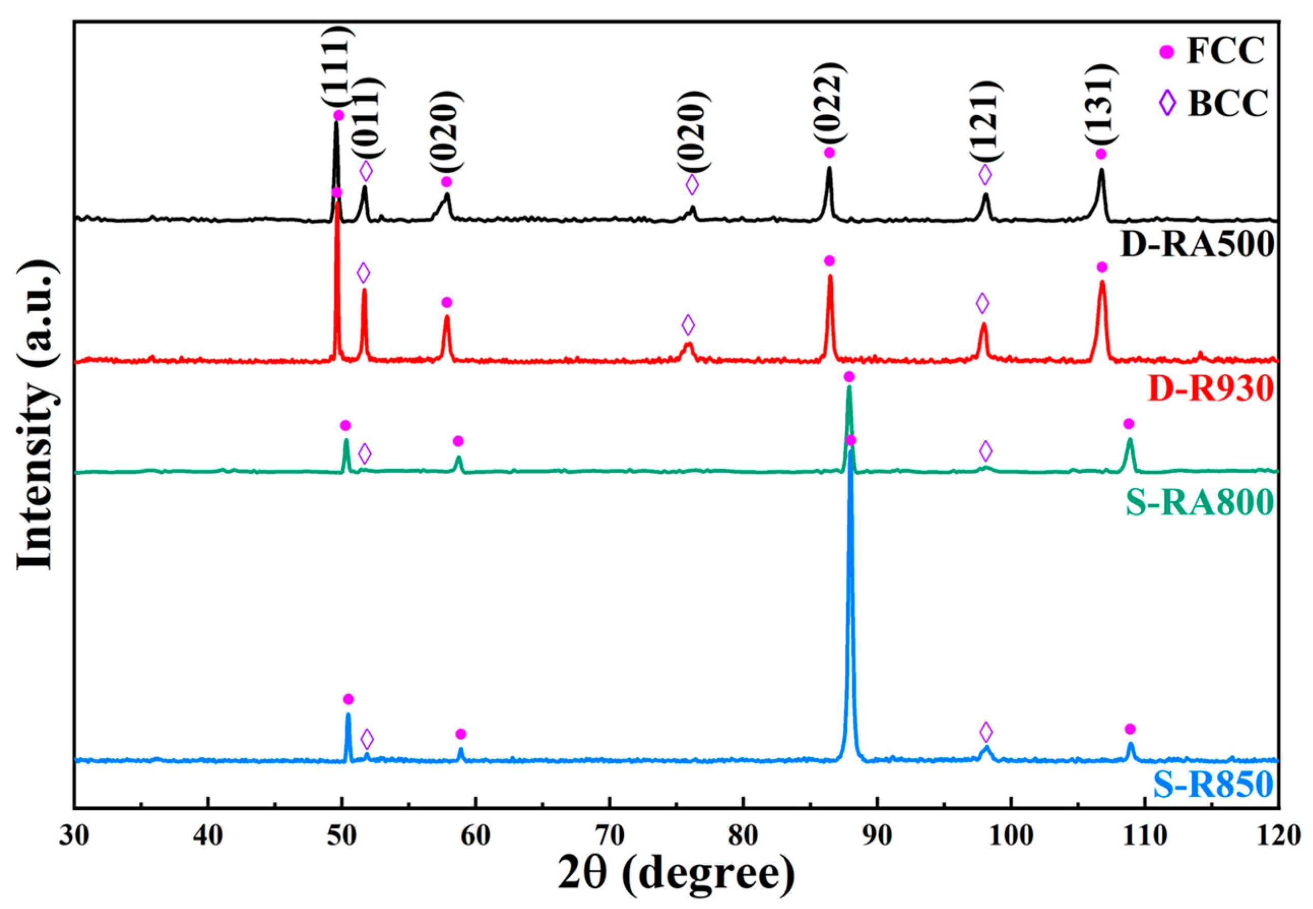
Figure 3.
SEM morphologies of the tested steels after heat treatment for (a) D-RA500, (b) D-R930, (c) S-R850, and (d) S-RA800 steel; (a1) EBSD phase maps (red and yellow colors refer to the austenite and ferrite phases, respectively) of the D-RA500 steel; (a2) grain size distributions of the D-RA500 steel.
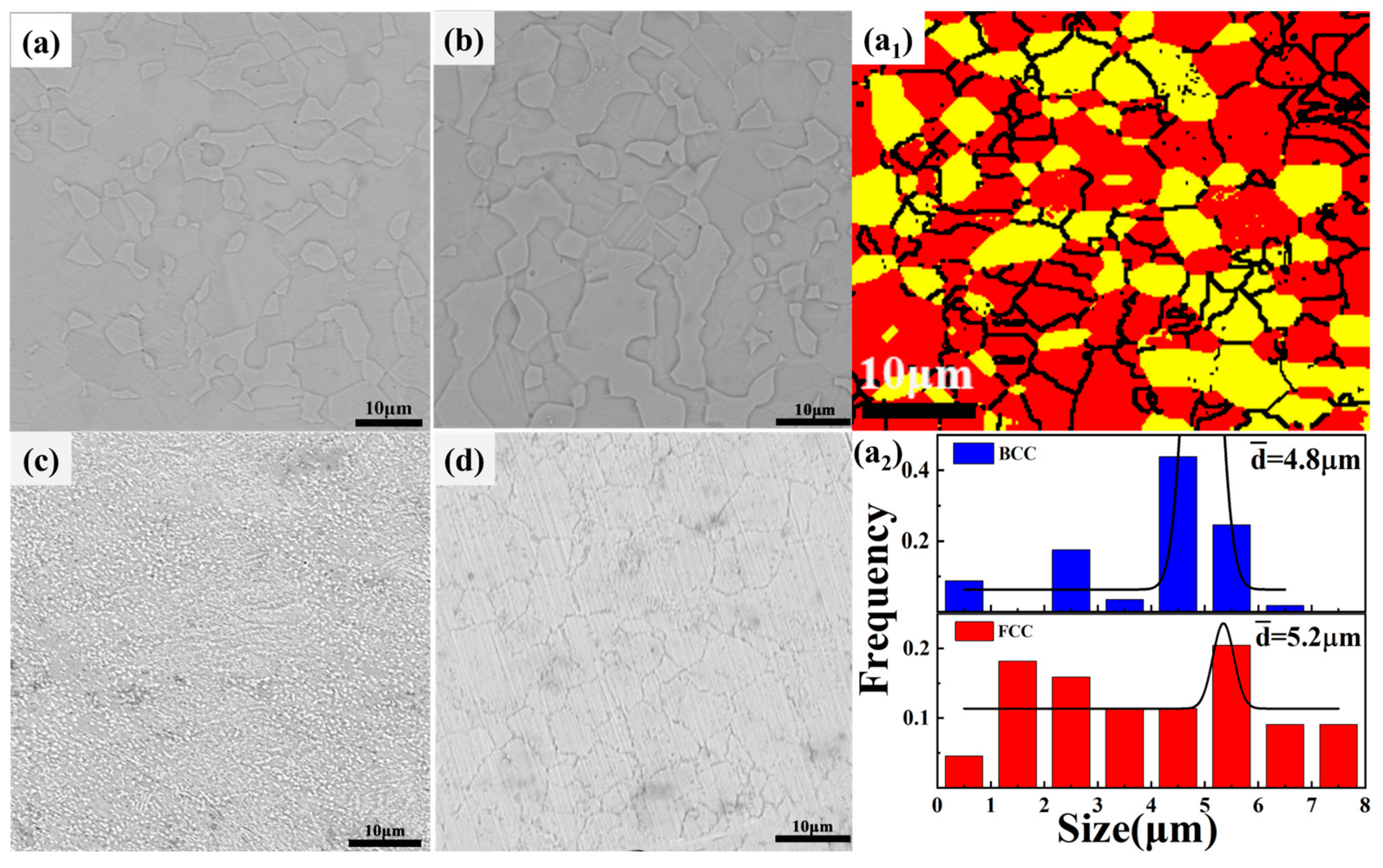
Figure 4.
(a,d) Bright-field TEM images of the D-RA500 alloy and dislocation line; γ: austenite, α: ferrite; (b,c) SAED patterns and corresponding DF images of D-RA500. (e) TEM micrograph of the steel; (g) dark-field TEM images of κ-carbide; (h) [101] zone axis SADPs of austenite and κ-carbide in as-annealed condition; (i) dispersed distribution of nano-sized κ precipitates [insert: enlarged morphology of one particle (f)].

Figure 5.
TEM micrographs showing the dislocation and twin structure morphologies of the tested steels (a–c); (d) magnified image of the non-recrystallized and recrystallized areas. (e) Bright-field TEM image of γ and B2; (f) STEM image. Austenitic matrix and B2 are identified by FFT patterns, and the B2 phase is detected by EDS maps in (g).
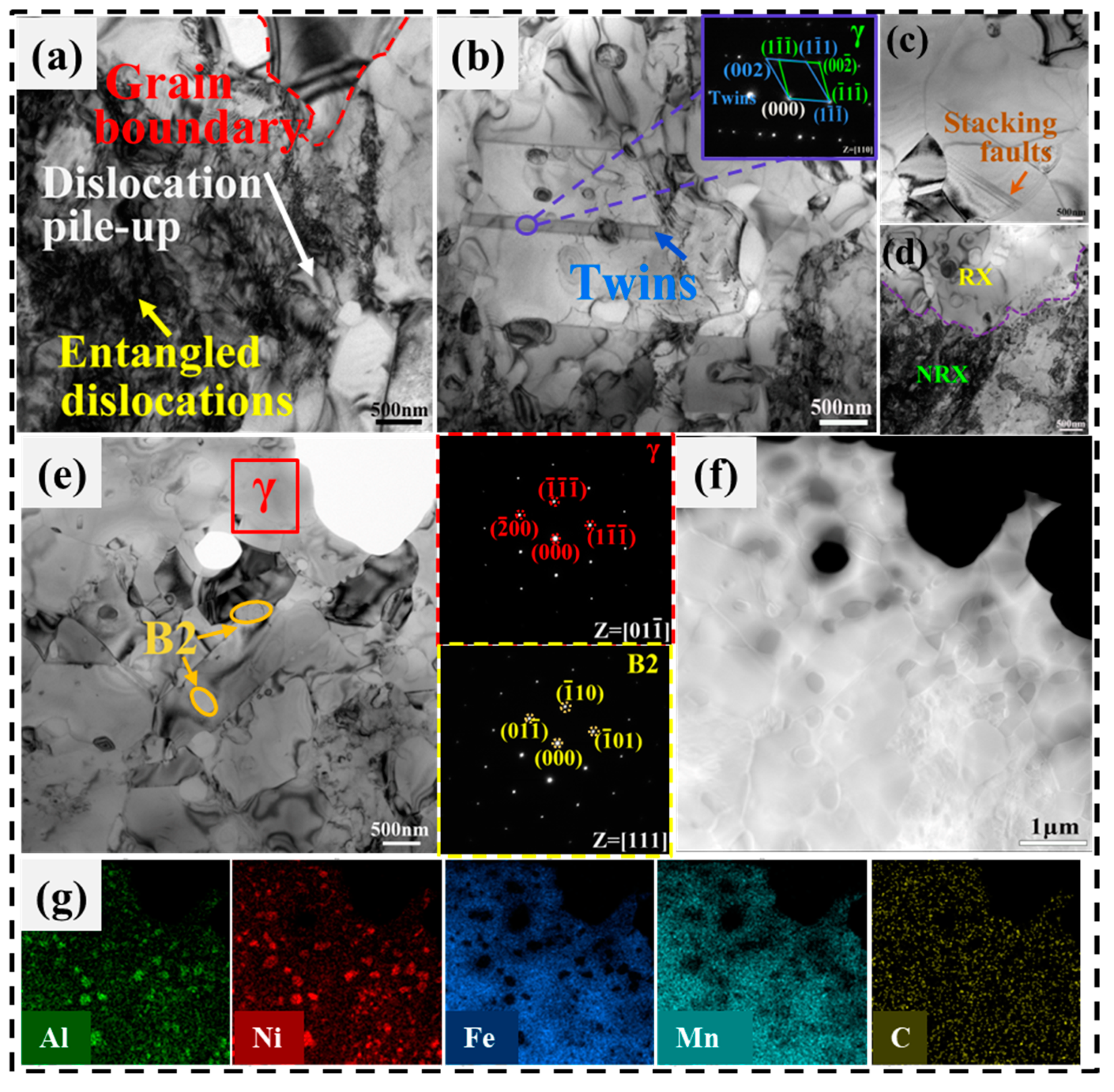
Figure 6.
(a) Engineering stress–strain curves and (b) strain-hardening rate, θ, true stress versus true strain. Fracture surfaces for the D-RA500 and the S-R850 steels also shown in the graphs.
Figure 6.
(a) Engineering stress–strain curves and (b) strain-hardening rate, θ, true stress versus true strain. Fracture surfaces for the D-RA500 and the S-R850 steels also shown in the graphs.
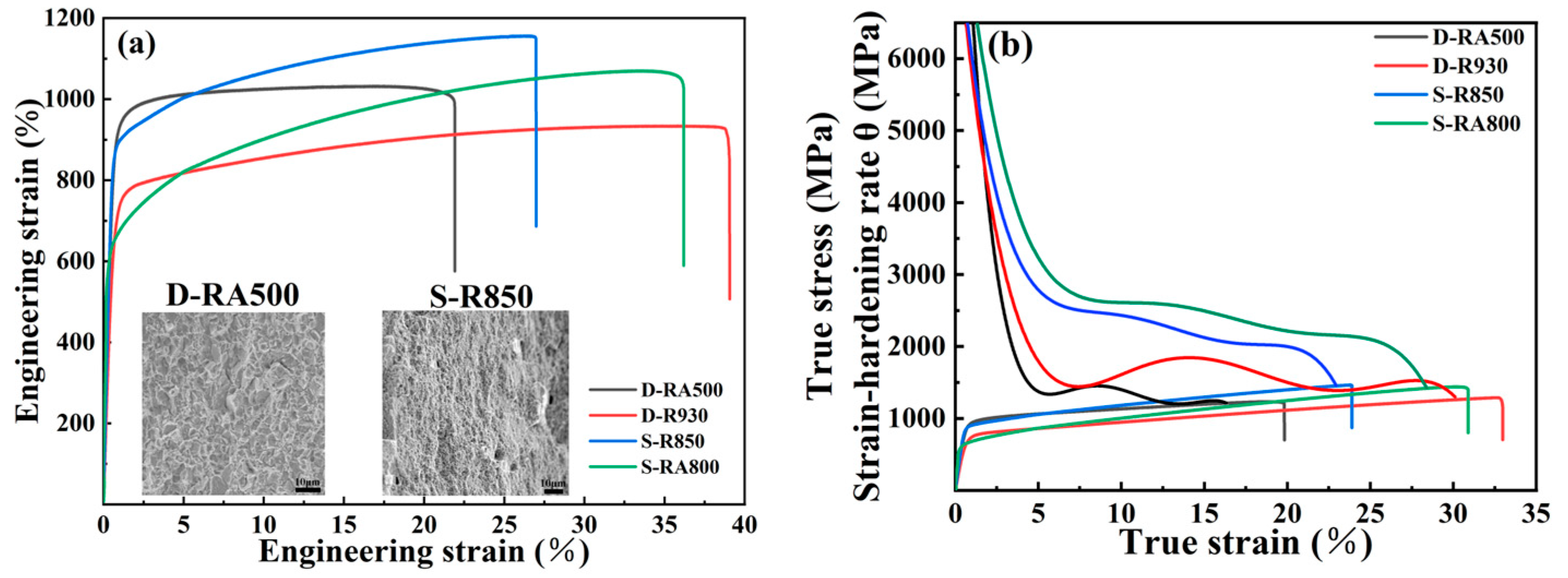
Figure 7.
TEM images of the deformed sample. (a) Bright-field TEM image showing the planar slip characteristics of dislocations; (b) Taylor lattices; (c) dislocations and (d) twins; (e) SAED pattern of the twin and matrix.
Figure 7.
TEM images of the deformed sample. (a) Bright-field TEM image showing the planar slip characteristics of dislocations; (b) Taylor lattices; (c) dislocations and (d) twins; (e) SAED pattern of the twin and matrix.
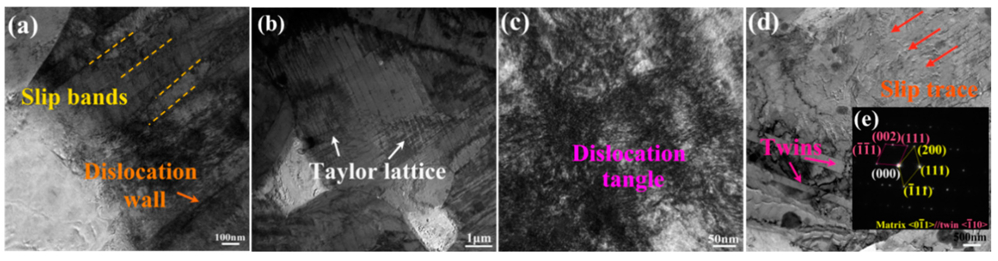
Figure 8.
TEM micrographs showing microstructural evolution after tensile deformation of steels: (a) random dislocations and high-density dislocation wall; (b) Taylor lattice and (c) SAED pattern of the matrix; (d) microbands; (e) deformation twins; (f) slip bands (dashed lines) and B2 (the red arrowed spot); (g) bright-field TEM image of B2; (h) HRTEM image and corresponding FFT pattern (inset); (i) zoomed-in image of (h); (j) corresponding STEM image; (k) EDS maps of the sample region in (g) indicate that it belongs to the B2 phases.

Figure 10.
Sketches illustrating the microstructural development of the tested steels, illustrating the formation mechanisms of the structure.
Figure 10.
Sketches illustrating the microstructural development of the tested steels, illustrating the formation mechanisms of the structure.


Table 1.
Chemical compositions and densities of experimental steels.
| Steel | Element Concentration (wt. %) | Density (g/cm3) | |||||
|---|---|---|---|---|---|---|---|
| Mn | Al | Ni | C | V | Fe | ||
| D | 26 | 10.2 | 0.98 | 0.15 | Bal. | 6.523 | |
| S | 29 | 5 | 12 | 1 | Bal. | 6.845 | |
Table 2.
Tensile properties of both steels in as-annealed and as-aged conditions.
| Specimen | State | YS (MPa) | UTS (MPa) | Total EI. (%) |
|---|---|---|---|---|
| D | as-annealed(D-R930) | 680 | 940 | 39 |
| as-aged(D-RA500) | 875 | 1035 | 21 | |
| S | as-annealed(S-R850) | 865 | 1150 | 27 |
| as-aged(S-RA800) | 630 | 1065 | 36 |
Table 3.
Strengthening contribution values of experimental steels.
| Steel | YS | |||||
|---|---|---|---|---|---|---|
| D-RA500 | 875 | 97 | 143 | 444 | 210 | |
| S-R850 | 865 | 97 | 212 | 373 | 167 |
Disclaimer/Publisher’s Note: The statements, opinions and data contained in all publications are solely those of the individual author(s) and contributor(s) and not of MDPI and/or the editor(s). MDPI and/or the editor(s) disclaim responsibility for any injury to people or property resulting from any ideas, methods, instructions or products referred to in the content. |
© 2024 by the authors. Licensee MDPI, Basel, Switzerland. This article is an open access article distributed under the terms and conditions of the Creative Commons Attribution (CC BY) license (https://creativecommons.org/licenses/by/4.0/).
Share and Cite
MDPI and ACS Style
Lv, X.; Wang, X.; Lan, A.; Qiao, J. Synergistic Effect of Al and Ni on Microstructure Evolutions and Mechanical Properties of Fe-Mn-Al-C Low-Density Steels. Metals 2024, 14, 495. https://doi.org/10.3390/met14050495
AMA Style
Lv X, Wang X, Lan A, Qiao J. Synergistic Effect of Al and Ni on Microstructure Evolutions and Mechanical Properties of Fe-Mn-Al-C Low-Density Steels. Metals. 2024; 14(5):495. https://doi.org/10.3390/met14050495
Chicago/Turabian StyleLv, Xiaodong, Xuejiao Wang, Aidong Lan, and Junwei Qiao. 2024. "Synergistic Effect of Al and Ni on Microstructure Evolutions and Mechanical Properties of Fe-Mn-Al-C Low-Density Steels" Metals 14, no. 5: 495. https://doi.org/10.3390/met14050495
Note that from the first issue of 2016, this journal uses article numbers instead of page numbers. See further details here.