Article

Detection of the Magnetic Easy Direction in Steels Using Induced Magnetic Fields

by
Edgard M. Silva
1,
Alysson M. R. Paula
1,
Josinaldo P. Leite
2,
Joao P. Leite
3,
Lucia S. S. Andrade
1,
Victor Hugo C. De Albuquerque
4 and
Joao Manuel R. S. Tavares
5,*
1
Instituto Federal de Educacao, Ciencia e Tecnologia da Paraiba, Rua Jose Americo de Almeida, 707-Nordeste I, Guarabira, Joao Pessoa-PB 58200-000, Brazil
2
Universidade Federal da Paraiba, Jardim Universitario, s/n-Castelo Branco, Joao Pessoa-PB 58051-900, Brazil
3
Centro de Ciências e Tecnologia, Universidade Federal de Campina Grande, R. Aprigio Veloso, 882, Campina Grande-PB 58429-900, Brazil
4
Programa de Pos-Graduacao em Informatica Aplicada, Universidade de Fortaleza, Av. Washington Soares, 1321, Edson Queiroz, Fortaleza-CE 60811-905, Brazil
5
Instituto de Ciencia e Inovacao em Engenharia Mecanica e Engenharia Industrial, Departamento de Engenharia Mecanica, Faculdade de Engenharia, Universidade do Porto, Rua Dr. Roberto Frias s/n, 4200-465 Porto, Portugal
*
Author to whom correspondence should be addressed.
Metals 2016, 6(12), 317; https://doi.org/10.3390/met6120317
Submission received: 30 September 2016 / Revised: 25 November 2016 / Accepted: 8 December 2016 / Published: 15 December 2016

Abstract

:
Conventional manufacturing processes cause plastic deformation that leads to magnetic anisotropy in processed materials. A deeper understanding of materials characterization under rotational magnetization enables engineers to optimize the overall volume, mass, and performance of devices such as electrical machines in industry. Therefore, it is important to find the magnetic easy direction of the magnetic domains in a simple and straightforward manner. The Magnetic easy direction can be obtained through destructive tests such as the Epstein frame method and the Single Sheet Tester by taking measurements in regions of irreversible magnetization usually called domains. In the present work, samples of rolled SAE 1045 steel (formed by perlite and ferrite microstructures) were submitted to induced magnetic fields in the reversibility region of magnetic domains to detect the magnetic easy direction. The magnetic fields were applied to circular samples with different thicknesses and angles varying from 0° to 360° with steps of 45°. A square sample with a fixed thickness was also tested. The results showed that the proposed non-destructive approach is promising to evaluate the magnetic anisotropy in steels independently of the geometry of the sample. The region studied presented low induction losses and was affected by magnetic anisotropy, which did not occur in other works that only took into account regions of high induction losses.

1. Introduction

Nondestructive testing has been used in materials characterization mainly to correlate microstructures and properties [1,2,3,4,5,6,7,8,9]. Magnetic properties are affected by thermo-mechanical processing that promotes anisotropy in the materials being processed. Destructive testing approaches such as Epstein frame and Single Sheet Testers (SST) have been used to detect magnetic anisotropy. Destructive and nondestructive testing approaches based on Barkhousen noise have also been used for the same purpose.
The magnetic properties of electrical steels such as core loss and magnetic induction depend on the microstructure and texture, which result from thermo-mechanical processes like slab reheating, hot- and cold-rolling, and final recrystallization annealing [10,11,12,13,14,15]. These processes can also generate noticeable magnetic anisotropy in the material because the magnetic behavior of steels strongly depends on their stress and strain states [11,13,16,17,18,19,20].
When testing polycrystalline ferromagnetic materials, the magnetic properties are often found to depend on the direction in which the properties were measured, and that there are certain macroscopic orientations, depending on the material, that are easier to magnetize (magnetic easy axis) [17,21,22,23].
An Epstein frame or Epstein square is a standard measurement device used to measure the magnetic properties of magnetic materials; it is especially used to test electrical steels [24]. In the case of industrial transformer steel sheets, the Epstein frame approach is based on destructive batch tests [12,13,25]. Emura et al. (2001) [12] studied the anisotropy of the magnetic properties of a 2% silicon steel. Permeability, core losses, remanence, and coercivity were analyzed in the Epstein strips cut at different angles (from 0° to 90°) relative to the rolling direction. They correlated the best and the worst magnetic properties with the rolling directions as being 0° and 54°, respectively.
The magnetic behavior of most commercial ferromagnetic steels is usually anisotropic and they usually present a magnetic easy axis [11,17,21,22,23,26,27]. Changes in the direction of this axis are related to mechanical changes and anomalies that occur in the manufacturing processes. Some works have proposed new nondestructive techniques based on Magnetic Barkhausen Noise (MBN) signals to determine the direction of the macroscopic magnetic easy axis. These techniques also offer the possibility of obtaining real-time parameters that quantify the magnetic anisotropy of the material under study [21,27,28]. Caldas-Morgan et al. [27] proposed a new technique to study the anisotropy based on angular MBN measurements that is referred to as the Continuous Rotational Barkhausen Method (CRBM). The authors found the macroscopic magnetic easy axis and quantified the anisotropy content considering the MBN energy. Their technique proved to be faster than the classic MBN technique. Capo [21] and Perez-Benitez [28] correlated uniaxial stress with the magnetic easy axis in ASTM 36 steel by the magnetic Barkhausen noise, and they noted a continuous rotation of the magnetic easy axis and the angular dependence of the coercivity and permeability.
The angular magnetic Barkhausen noise technique has also been applied to characterize the magnetic anisotropy in pipeline steels [17,23,29]. Clapham et al. [17] showed the difficulty of finding a correlation between the crystallographic texture of an API5L-X70 pipeline steel and the angular dependence of the MBN energy, and their results suggested that the plastic deformation and residual stress are responsible for the magnetic easy axis. Ortiz et al. [23] proposed a method to determine the magnetic easy axis of Roll Magnetic Anisotropy in API-5L steels. The method took into account the fact that the angular dependence of the energy corresponding to the main peak of the Magnetic Barkhausen signal presents uniaxial anisotropy independently of the angular dependence of the magnetocrystalline energy in the material. MBN is mainly influenced by the rolling magnetic anisotropy due to the presence of pearlite bands and the grain shape preferred orientation along the rolling direction; both of which influence the domain wall dynamics. Ortiz et al. [29] also studied the influence of the maximum applied magnetic field on the angular dependence of the energy of the Magnetic Barkhausen Noise signal in three different API5L pipeline steels. These authors noticed a correlation between the shape of the angular dependence of the MBN signal with the applied magnetic field.
In this study, measurements of an induced magnetic field generated by direct current obtained in the reversibility region of magnetic domains are used to study the anisotropy of rolled steel. The proposed approach was revealed to be promising to follow the magnetic behavior of ferrite transformation [30], and it is applied here for the first time to detect the macroscopic anisotropy and easy magnetic direction in a steel composed of ferrite and perlite phases. An as-received rolled and annealed SAE 1045 steel was used in order to investigate if even an annealed material with ferrite and perlite phases could present a macroscopic easy direction. Another important objective was to propose a new nondestructive approach to detect local magnetic anisotropy in steels. The Epstein frame method and the Single Sheet Tester measurements result in averaged magnetic parameters of the tested steel. Therefore, they are not suitable to investigate local magnetic properties. The main idea of the approach suggested here is to assess local magnetic anisotropy from magnetic field measurements in order to characterize the microstructure and magnetic anisotropy.
The proposed approach is nondestructive, is not affected by the geometry of the sample, is easy to use and interpret, and can assess the local magnetic easy direction in areas of just 4.5 cm2. In addition to being destructive, the Epstein and small single sheet-based approaches require sample sizes from 84 to 93 cm2 and 25 to 1296 cm2, respectively [20,22,25,31,32]. These approaches can also be used in nondestructive tests; However, the test areas of the samples under study should have larger dimensions. For the techniques based on the Barkhausen noise signal that have been applied for the same purpose, sample sizes from 50.4 to 100 cm2 have been used [17,21,23,26,27,28,29,33].

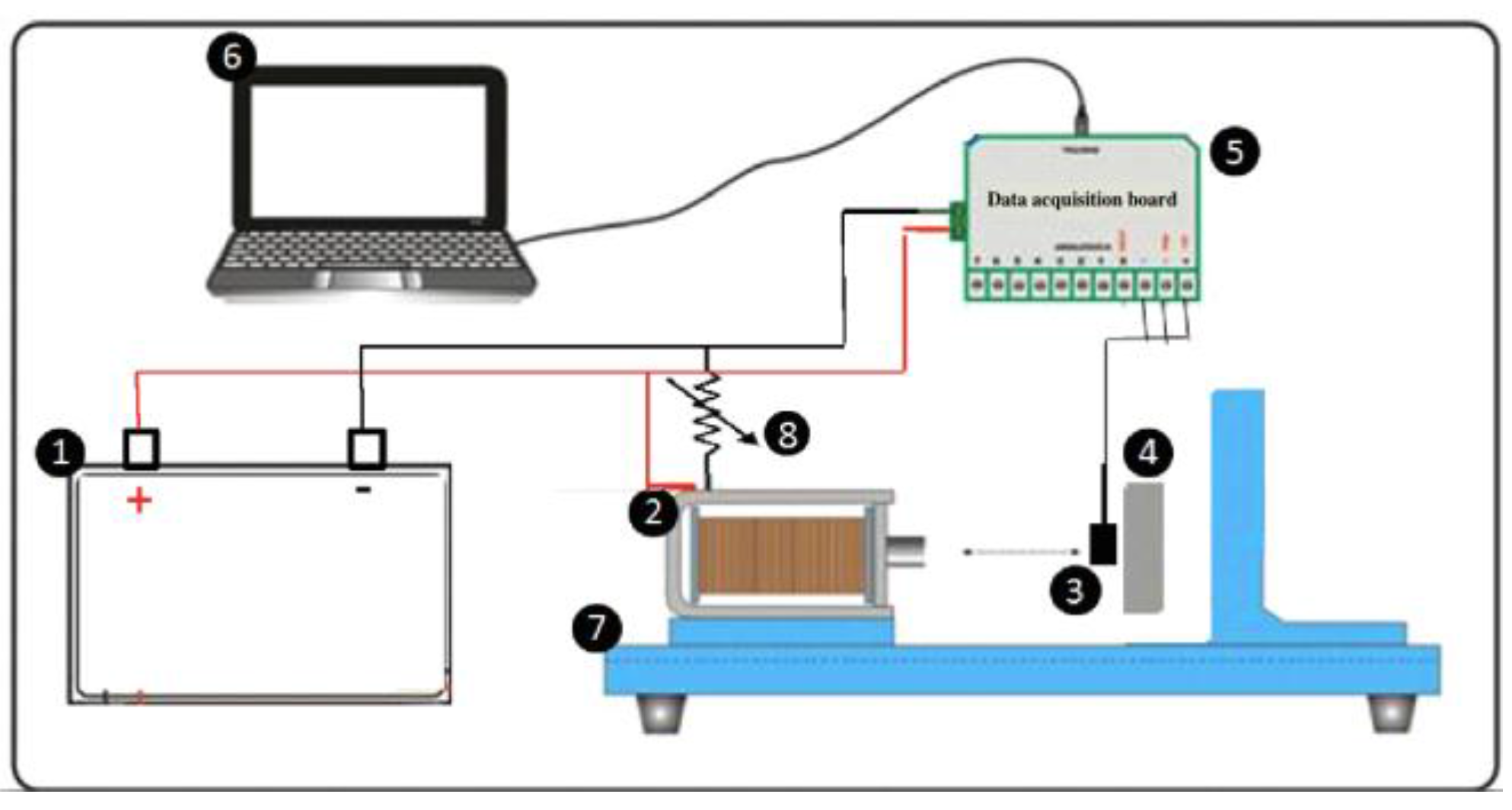
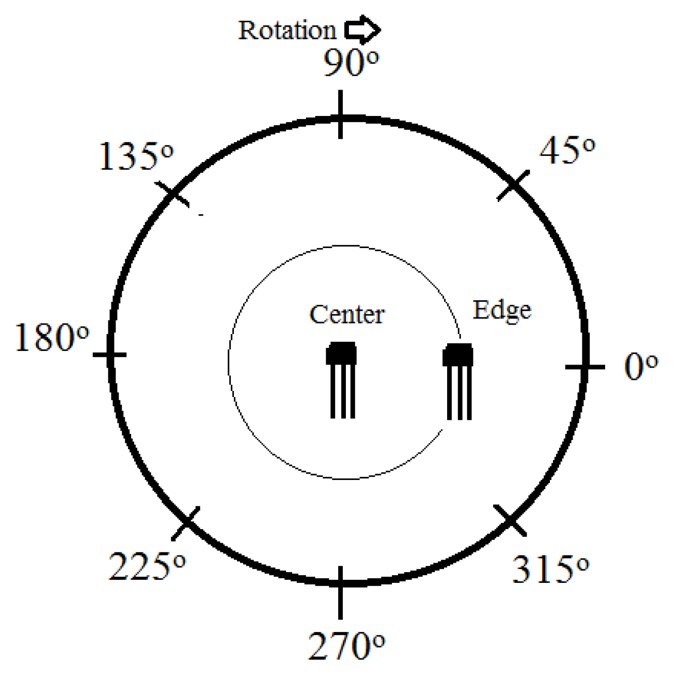
2. Materials and Methods

The as-received rolled and annealed commercial SAE 1045 steel samples with a diameter of 24 mm and thicknesses of 2, 4, 8, and 11 mm were submitted to a magnetic field of 188 A/m. The measures were acquired at the center of the samples and 6 mm from this point according to the following angles: 0°, 45°, 90°, 135°, 180°, 225°, 270°, 315°, and 360°. The experiment was carried out using samples with different geometries to show that the easy magnetic direction can be detected independently of the sample geometry and the robustness of the outcome of this nondestructive inspection. The test surface was perpendicular to the rolling direction as shown in Figure 1. The external magnetic field (H) was generated by a solenoid and applied perpendicularly to the circular test face. The Hall sensor was placed on the test surface at two locations: (1) at the center point of the sample under test and (2) at 6 mm from this point (Figure 1). In addition, the direction of the Hall sensor axis was parallel to the test surface.
The as-received rolled and annealed SAE 1045 steel samples were subjected to metallographic analysis both longitudinally and transversally, enabling their microstructure to be studied. The surfaces of the samples were etched with 2% nital solution and analyzed through an optical microscopy (FX 35XD NIKON Optical Microscopy, Alzenau, Germany) that has an image acquisition system. The surfaces were also analyzed through a scanning electron microscopy (SUPERSCAN SSX-550 SEM, Shimadzu Corporation, Kyoto, Japan). The average size of the ferrite grains was determined in the function of the rotational angle; therefore, angle values between 0° and 90° were used in order to analyze the existence of residual deformation based on the Heyn lineal intercept procedure.
The experimental setup used to study the material samples under analysis was based on the application and assessment of induced magnetic fields as shown in Figure 2. In this setup, a solenoid was responsible for generating the external magnetic field by direct current, and a Hall Effect sensor (from Honeywell, Morris Plains, NJ, USA, model SS495A) was used to determine the magnetic flux density. External magnetic fields up to 282 A/m were applied to generate the induced fields in the reversibility region of the magnetic domain, leaving no permanent magnetization in the samples under test. One hundred and fifty signals were acquired from each sample. In addition, the external magnetic field was considered to correspond to the field measured by the Hall sensor without the sample under test, and that the ideal value for the external field is the one to be applied so that better discriminative signal amplitudes can be obtained. Thus, the ideal external field was considered as the one that led to the highest difference found between the induced magnetic fields at the center of the sample under test and at 6 mm way from this point (Figure 1), which is called amplitude measurement.

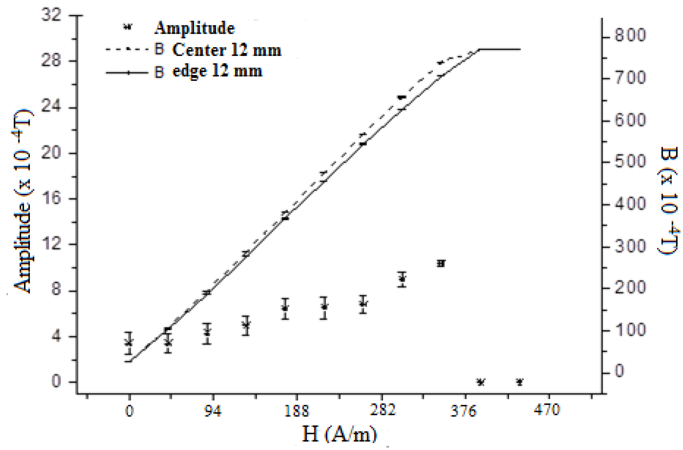
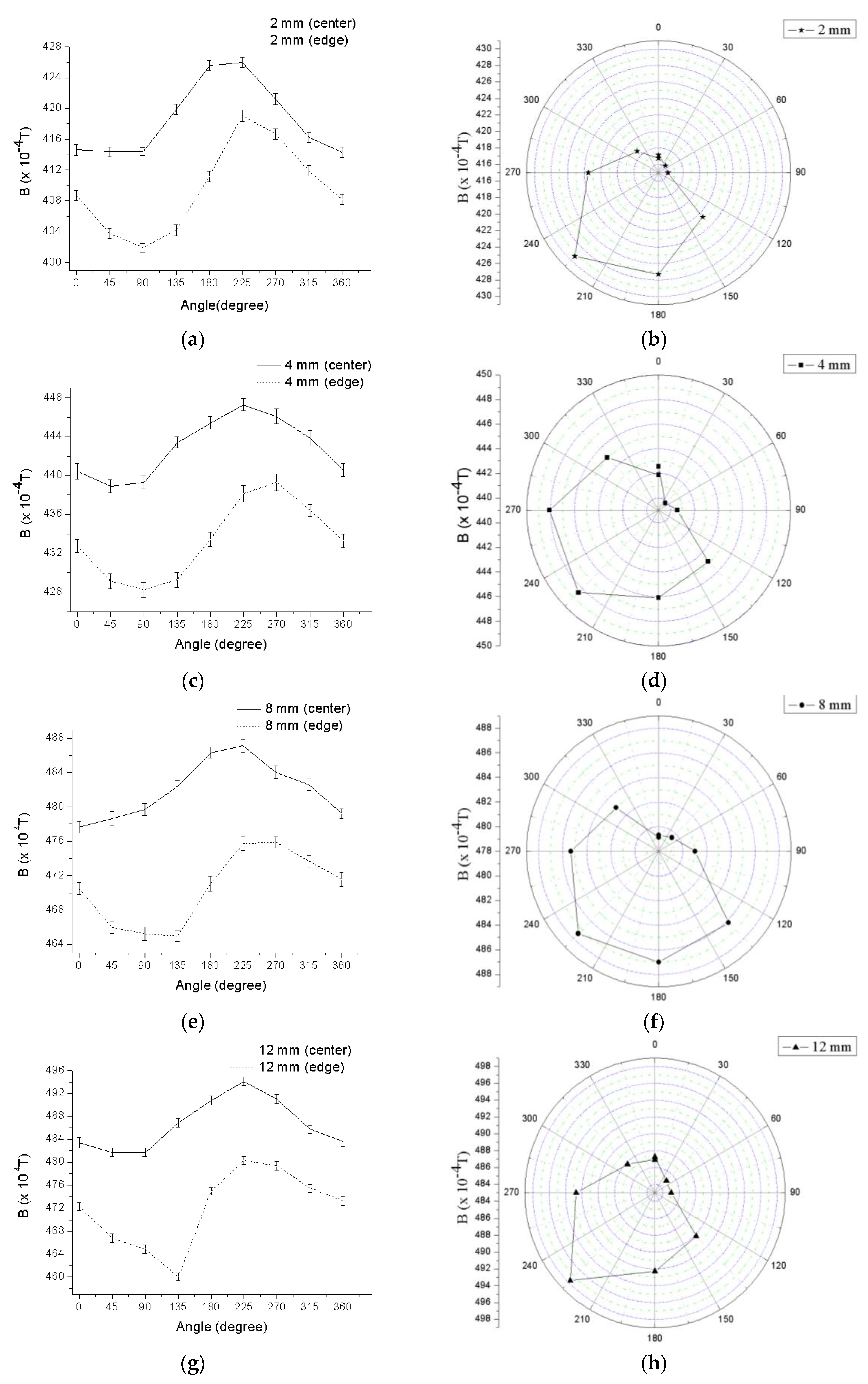
3. Results and Discussion

Figure 3 shows the changes of the induced magnetic field (B) versus the external magnetic field (H) applied to the samples that were 12 mm thick. The measures were acquired at the center of the samples and also at 6 mm from it, using external magnetic fields up to the saturation of the sensor. Figure 3 also presents the difference, called amplitude measurement, between the induced magnetic fields at these two points and the applied external fields. These values increased up to a maximum peak and then decreased. The latter reduction of amplitude found was due to the beginning of the saturation of the Hall sensor. The external magnetic field of 188 A/m was considered to be ideal to obtain better discriminating amplitudes. The same procedure was applied to the samples with other thicknesses and the external magnetic field that resulted in the maximum amplitude was found to be the same (188 A/m).
Figure 3 shows a linear relation between B and H, which corresponds to the reversibility region of the magnetic material. The region of reversibility of the magnetic domain corresponds to the magnetized region where the domains are randomly oriented, and the application of an external magnetic field does not cause its permanent magnetization, perpetual motion, or a residual field; and therefore, the demagnetization of the material is unnecessary [34,35,36,37]. This region also belongs to the one of low induction losses and these losses are related to the energy dissipated by the displacement of the walls of the magnetic domains [20,32,36]. Landgraf et al. [32] associated the area between the two induction lines of maximum permeability of a magnetization curve of a material as hysteresis losses of low induction and the complementary area above and below those lines as hysteresis losses of high induction. Here, the measurements were carried out in the linear region and low induction one of the magnetization curve, and an external magnetic field value of 188 A/m was found to be the most suitable for studying the magnetization easy direction.
This work also investigated the magnetic anisotropy of the steel studied. Several studies have been developed for this purpose [10,12,13,16,21,26,38,39,40], some used destructive tests and others used nondestructive tests, but did so using samples of bigger dimensions than the ones used in the present work, as already mentioned. The present work demonstrates that the proposed approach can successfully identify the local easy direction independently of the sample geometry and in test areas of just 4.5 cm2, which does not occur with other nondestructive methods that require areas greater than 25 cm2. The authors of related works have shown that the magnetic properties of ferromagnetic materials suffer interference from the material microstructure and also from the stress conditions due to plastic deformation. This deformation is caused by conventional manufacturing processes, leading to anisotropic behavior in the magnetic properties of the processed materials.
The procedure used here to study the magnetic anisotropy is based on measures acquired at two different regions of the samples: in the center and near to the edge of the samples, and rotating the samples from 0° to 360°. The behavior obtained for the induced magnetic field versus the rotation angle can be seen in Figure 4. As all tested samples were from the same commercial material, one can conclude that no alteration of the material permeability occurred. The external magnetic field was kept constant.
The results in Figure 4 show that the induced magnetic field was higher in the center of the samples and decreased when approaching the edge of the samples. On moving from the center to the edge, the permeability effect of the external environment—i.e., the air—has a more pronounced influence on the decreasing values of B.
The relation between the induced magnetic field and the rotation angle, depicted in Figure 4, has an anisotropic behavior and changes according to the relative position of the samples to the incident magnetic field and also according to the rotation of the samples. Other studies also detected the change in the induced magnetic field due to the rotation of the samples, indicating that magnetization curves suffer interference from the plastic deformation, which causes magnetic anisotropy [17,20,27,28,32,41]. Figure 4 also shows that the measures acquired at the center of the samples have peak values for angles of around 225°. These peak values are measured not only at the center of the samples, but also in the associated polar plots, which suggests that the angle of 225° corresponds to the easy magnetization. This also means that the magnetic losses are lower in this direction. The present work was performed with a direct current and fixed pole; however, if the pole was changed, the polar graph would show higher values of induced magnetic field around the angle of 45°, since the angles of 45° and 225° are opposites along the direction of easy magnetization. Ortiz et al. [23] showed the formation of polar curves with “8” shapes in materials with the same microstructure. The author used alternating current instead of direct current and associated the “8” shapes due to the displacement of the magnetic domain walls. In the reversibility region movements of the domain walls also occur; however, these movements are reversible.
The data in Figure 4 also suggest that the measures acquired displaced from the center of the samples have lower induced magnetic fields for the rotation angles between 0° and 180°, which was not observed in the measures obtained at the center of the samples. This reduction is attributed to the demagnetizing effect of perlite presented in the microstructure. Ortiz et al. [23] also observed this behavior in steels with the same constituents.
Emura et al. [12] studied the magnetic induction field resultant from the application of external magnetic fields of 2500 A/m (B25) and 5000 A/m (B50) versus the rotated angle relative to the rolling direction in a non-oriented 2% Si steel. The authors found a minimum field at a rotation angle of around 54°, which indicates a less favorable condition for magnetization at this orientation compared to orientations parallel and perpendicular to the rolling direction.
Landgraf et al. [32] also observed in non-oriented steels the presence of the most unfavorable magnetic properties for rotation angles between 45° and 60°. Emura, Landgraf and co-workers [12,20,32] used Epstein strips cut at 0°, 15°, 30°, 45°, 60°, 75°, and 90° from the rolling direction in their analysis with the applied field in hysteresis losses in the high induction region. The production of these materials evolves many rolling and recrystallization steps, which cause anisotropy. Despite their designation, the non-oriented steels have texture components and their easy magnetization direction corresponds to the direction of plastic deformation. In this work, a strain state seemed to exist at an angle of 45°.
Figure 5a shows the changes found at the center of the samples with thicknesses of 2, 4, 6, 8, and 12 mm in terms of the induced magnetic field. In the samples with thicknesses of 8 and 12 mm, the induced magnetic field seems to be independent of the thickness. To investigate the possible effect of the shape of the samples, a squared shape sample with a diagonal of 24 mm and thickness of 12 mm was submitted to the same conditions as the other samples, and the results were compared against the ones obtained with the sample with a diameter of 24 mm and the same thickness. The findings obtained for the squared sample are depicted in Figure 5b and were similar to the ones obtained for the circular sample, suggesting that even with square sections the easy direction can be successfully detected.
Standard tests used in anisotropy analysis determine the magnetic angle associated with low magnetic loss. To carry out these tests, a magnetic field is applied in the region of high induction loss of the hysteresis loop [20,32,36]; this is enough to promote irreversible modifications in the position of the magnetic domains. These tests need to physically remove samples from the material/device/machine under test and so are classified as destructive testing techniques. The experiment conducted in this work has shown that, by applying a magnetic field of low intensity, the magnetization easy direction of the part under study can be obtained without the need to remove any material as a sample, which means that it is a non-destructive approach. High induction losses are related to magnetization vector rotation as well as wall annihilation and recreation; on the other hand, low induction losses are associated to energy dissipation due to displacements of the domain walls [32,36].
The region studied in this work belongs to the low induction loss regions and proved to be sensitive to magnetic anisotropy; this has not been observed in other works that only reported findings in the high induction loss regions [12,20,32].
Figure 6 depicts the microstructure of the surfaces where the induced magnetic field measures were collected. The images obtained for the microstructure are in accordance to what is expected for the commercial steel under study. Hence, Figure 6a shows the image obtained by optical microscopy where ferrite is associated to the lighter regions and perlite to the darker ones. Figure 6b shows the image obtained by scanning electronic microscopy and the existence of the lamellar perlite structure (cementite lamellar + ferrite phases) can be seen. The average grain size of the ferrite was determined based on the results obtained by varying the rotational angle between 0° and 90° that was performed in order to analyze the existence of residual deformation, i.e., the deformation of the ferrite in one specific direction. The Heyn lineal intercept procedure [24] was used and the results obtained for the average grain size of ferrite are the ones represented in Figure 6c. Figure 6c shows that the ferrite has the largest average grain size in the 45° direction, which corresponds to the magnetization easy direction. Although the materials undergo a thermal annealing treatment at the final stage of production after rolling as was confirmed in this case, there is still a preferred direction for grain orientation. The variation of induced magnetic field with the rotation angle is related to this plastic deformation, generating sufficient magnetic anisotropy to be detected. The ferrite grains are deformed in the direction of the angle of around 45°, which was found to have the strongest induced magnetic field. When a circular sample of an isotropic material is rotated around its central vertical axis, a constant magnetic induction is expected. However, in this study, the ferrite phase presented anisotropy in the 45° direction, which led to changes in the induced magnetic field.
The production of these materials involves many rolling steps and recrystallization (recovery and grain growth) thermal treatments, which cause anisotropy. In the microstructures formed by ferrite and perlite, the magnetic flux line density tends to pass more easily through the ferrite phase than the perlite phase due to their differences in permeability. The perlite has a lamellar structure that hinders the domain movements (Figure 6b). Ortiz et al. [29] studied the interaction between magnetic flux lines and ferrite and perlite microstructures and showed that the higher coercive field of the perlite affects the direction of the magnetic flux vectors which changes near the region corresponding to the pearlite bands and follows the ferrite microstructure. The authors found a coercive field of 8 A/m associated to the ferrite and 160 A/m to the perlite phase.
The results presented here show that the proposed approach is able to determine the magnetization easy direction of the studied steel, regardless of the geometry of the samples. This approach also detected the microstructural anisotropy that was responsible for the magnetic anisotropy of the material. Both the ferrite phase and the higher induced magnetic field were detected at an angle of 45°.

4. Conclusions

In this study, measures of induced magnetic fields generated by direct current obtained in the reversibility region of magnetic domains were used to study anisotropy in a rolled steel. The objective was to propose a nondestructive test to detect local magnetic anisotropy in steels. The findings obtained allow the following conclusions:
(1)
The proposed approach can be successfully applied for experimental evaluation of magnetic anisotropy in steels. The approach is non-destructive and can be used in the study of local magnetic properties and of magnetic properties of steels according to different magnetization directions. This approach was also able to determine the magnetization easy direction of the steel studied in samples with different dimensions and even different geometries.
(2)
The proposed approach uses direct current to generate an external magnetic field that is applied in the region of magnetic reversibility. This region belongs to the low induction loss region and proved to be sensitive to magnetic anisotropy, which was not observed in other works that only reported findings in the high induced losses region.
As for future works, we intend to use computational classifiers to identify the magnetic anisotropy based on the data collected here. Another further study will be to determine the minimum dimensions that a sample can have in order to guarantee accurate testing results.

Acknowledgments

EMS acknowledges the sponsorship from the Coordination for the Improvement of Higher Education Personnel (CAPES), in Brazil, through the scholarship process BEX 2634/15-5 at Faculdade de Engenharia da Universidade do Porto (FEUP), in Portugal, and from the Federal Institution of Paraiba (IFPB) in Brazil. VHCA acknowledges CNPq for the Grants 470501/2013-8 and 301928/2014-2. JMRST gratefully acknowledges the funding from the Project NORTE-01-0145-FEDER-000022-SciTech—Science and Technology for Competitive and Sustainable Industries, cofinanced by “Programa Operacional Regional do Norte” (NORTE2020), through “Fundo Europeu de Desenvolvimento Regional” (FEDER).

Author Contributions

Study design: E.M.S., V.H.C.A., and J.M.R.S.T.; Experimental work: A.M.R.P.L., J.P.L, J.P.L., and A.L.S.S.A.; Results analysis and manuscript preparation: all authors; Manuscript proof and submission: E.M.S., V.H.C.A., and J.M.R.S.T.

Conflicts of Interest

The authors declare no conflict of interest.

References

  1. De Albuquerque, V.H.C.; Filho, P.P.R.; Cavalcante, T.S.; Tavares, J.M.R.S. New computational solution to quantify synthetic material porosity from optical microscopic images. J. Microsc. 2010, 240, 50–59. [Google Scholar] [CrossRef] [PubMed]
  2. De Albuquerque, V.H.C.; de Alexandria, A.R.; Cortez, P.C.; Tavares, J.M.R.S. Evaluation of multilayer perceptron and self-organizing map neural network topologies applied on microstructure segmentation from metallographic images. NDT E Int. 2009, 42, 644–651. [Google Scholar] [CrossRef]
  3. De Albuquerque, V.H.C.; Silva, E.M.; Leite, J.P.; Moura, E.P.; Freitas, V.L.A.; Tavares, J.M.R.S. Spinodal decomposition mechanism study on the duplex stainless steel UNS S31803 using ultrasonic speed measurements. Mater. Des. 2010, 31, 2147–2150. [Google Scholar] [CrossRef]
  4. De Albuquerque, V.H.C.; Melo, T.A.A.; Oliveira, D.F.; Gomes, R.M.; Tavares, J.M.R.S. Evaluation of grain refiners influence on the mechanical properties in a CuAlBe shape memory alloy by ultrasonic and mechanical tensile testing. Mater. Des. 2010, 31, 3275–3281. [Google Scholar] [CrossRef]
  5. Moreira, F.D.L.; Kleinberg, M.N.; Arruda, H.F.; Freitas, F.N.C.; Parente, M.M.V.; de Albuquerque, V.H.C.; Reboucas Filho, P.P. A novel Vickers hardness measurement technique based on Adaptive Balloon Active Contour Method. Expert Syst. Appl. 2016, 45, 294–306. [Google Scholar] [CrossRef]
  6. Freitas, V.L.A.; de Albuquerque, V.H.C.; Silva, E.M.; Silva, A.A.; Tavares, J.M.R.S. Nondestructive characterization of microstructures and determination of elastic properties in plain carbon steel using ultrasonic measurements. Mater. Sci. Eng. A 2010, 527, 4431–4437. [Google Scholar] [CrossRef]
  7. Nunes, T.M.; de Albuquerque, V.H.C.; Papa, J.P.; Silva, C.C.; Normando, P.G.; Moura, E.P.; Tavares, J.M.R.S. Automatic microstructural characterization and classification using artificial intelligence techniques on ultrasound signals. Expert Syst. Appl. 2013, 40, 3096–3105. [Google Scholar] [CrossRef]
  8. Papa, J.P.; Nakamura, R.Y.M.; de Albuquerque, V.H.C.; Falcao, A.X.; Tavares, J.M.R.S. Computer techniques towards the automatic characterization of graphite particles in metallographic images of industrial materials. Expert Syst. Appl. 2013, 40, 590–597. [Google Scholar] [CrossRef]
  9. Normando, P.G.; Moura, E.P.; Souza, J.; Tavares, S.S.M.; Padovese, L.R. Ultrasound, eddy current and magnetic Barkhausen noise as tools for sigma phase detection on a UNS S31803 duplex stainless steel. Mater. Sci. Eng. A 2010, 527, 2886–2891. [Google Scholar] [CrossRef]
  10. Chen, S.; Butler, J.; Melzer, S. Effect of asymmetric hot rolling on texture, microstructure and magnetic properties in a non-grain oriented electrical steel. J. Magn. Magn. Mater. 2014, 368, 342–352. [Google Scholar] [CrossRef]
  11. Chwastek, K. Anisotropic properties of non-oriented steel sheets. IET Electr. Power Appl. 2013, 7, 575–579. [Google Scholar] [CrossRef]
  12. Emura, M.; Campos, M.F.; Landgraf, F.J.G.; Teixeira, J.C. Angular dependence of magnetic properties of 2% silicon electrical steel. J. Magn. Magn. Mater. 2001, 226–230, 1524–1526. [Google Scholar] [CrossRef]
  13. Fryskowski, B. Experimental evaluation of magnetic anisotropy in electrical steel sheets. J. Magn. Magn. Mater. 2008, 320, 515–522. [Google Scholar] [CrossRef]
  14. Qin, J.; Yang, P.; Mao, W.; Ye, F. Effect of texture and grain size on the magnetic flux density and core loss of cold-rolled high silicon steel sheets. J. Magn. Magn. Mater. 2015, 393, 537–543. [Google Scholar] [CrossRef]
  15. Sonboli, A.; Toroghinejad, M.R.; Edris, H.; Szpunar, J.A. Effect of deformation route and intermediate annealing on magnetic anisotropy and magnetic properties of a 1 wt % Si non-oriented electrical steel. J. Magn. Magn. Mater. 2015, 385, 331–338. [Google Scholar] [CrossRef]
  16. Chernenkov, Y.P.; Ershov, N.V.; Lukshina, V.A.; Fedorov, V.I.; Sokolov, B.K. An X-ray diffraction study of the short-range ordering in the soft-magnetic Fe-Si alloys with induced magnetic anisotropy. Phys. B Condens. Matter 2007, 396, 220–230. [Google Scholar] [CrossRef]
  17. Clapham, L.; Heald, C.; Krause, T.W.; Atherton, D.L.; Clark, P. Origin of a magnetic easy axis in pipeline steel. J. Appl. Phys. 1999, 86, 1574–1580. [Google Scholar] [CrossRef]
  18. Elmassalami, M.; Sousa, I.P.; Areiza, M.C.L.; Rebello, J.M.A.; Elzubair, A. On the magnetic anisotropy of superduplex stainless steel. J. Magn. Magn. Mater. 2011, 323, 2403–2407. [Google Scholar] [CrossRef]
  19. Fiorillo, F. Anisotropy and magnetization process in soft magnets: Principles, experiments, applications. J. Magn. Magn. Mater. 2006, 304, 139–144. [Google Scholar] [CrossRef]
  20. Landgraf, F.J.G.; Emura, M.; Teixeira, J.C.; Campos, M.F.; Muranaka, C.S. Anisotropy of the magnetic losses components in semi-processed electrical steels. J. Magn. Magn. Mater. 1999, 196, 380–381. [Google Scholar] [CrossRef]
  21. Sanchez, J.C.; Benitez, J.P.; Padovese, L.R. Analysis of the stress dependent magnetic easy axis in ASTM 36 steel by the magnetic Barkhausen noise. NDT E Int. 2007, 40, 168–172. [Google Scholar] [CrossRef]
  22. Gallaugher, M.; Ghosh, P.; Knight, A.M.; Chromik, R.R. The effect of easy axis misorientation on the low induction hysteresis properties of non-oriented electrical steels. J. Magn. Magn. Mater. 2015, 382, 124–133. [Google Scholar] [CrossRef]
  23. Ortiz, P.M.; Benitez, J.A.P.; Hernandez, J.H.E.; Caleyo, F.; Hallen, J.M. On the estimation of the magnetic easy axis in pipeline steels using magnetic Barkhausen noise. J. Magn. Magn. Mater. 2015, 374, 67–74. [Google Scholar] [CrossRef]
  24. ASTM International. ASTM E 112–96(2004) Standard Test Methods for Determining Average Grain Size; ASTM International: West Conshohocken, PA, USA, 2004. [Google Scholar]
  25. Yonamine, T.; Landgraf, F.J. Correlation between magnetic properties and crystallographic texture of silicon steel. J. Magn. Magn. Mater. 2004, 272–276, E565–E566. [Google Scholar] [CrossRef]
  26. Deme, A.B.; Szabo, I.A.; Cserhati, C. Effect of anisotropic microstructure on magnetic Barkhausen noise in cold rolled low carbon steel. J. Magn. Magn. Mater. 2010, 322, 1748–1751. [Google Scholar] [CrossRef]
  27. Morgan, M.C.; Padovese, L.R. Fast detection of the magnetic easy axis on steel sheet using the continuous rotational Barkhausen method. NDT E Int. 2012, 45, 148–155. [Google Scholar] [CrossRef]
  28. Benitez, J.A.P.; Sanchez, J.C.; Padovese, L.R. Characterization of angular dependence of macroscopic magnetic properties in ASTM 36 steel using magnetic Barkhausen noise. NDT E Int. 2007, 40, 284–288. [Google Scholar] [CrossRef]
  29. Ortiz, P.M.; Benitez, J.A.P.; Hernandez, J.H.E.; Caleyo, F.; Mehboob, N.; Grossinger, R.; Hallen, J.M. Influence of the maximum applied magnetic field on the angular dependence of Magnetic Barkhausen Noise in API5L steels. J. Magn. Magn. Mater. 2016, 401, 108–115. [Google Scholar] [CrossRef]
  30. Silva, E.M.S.; Leite, J.P.; Neto, F.A.F.; Leite, J.P.; Fialho, W.M.L.; Albuquerque, V.H.C.; Tavares, J.M.R.S. Evaluation of the Magnetic Permeability for the Microstructural Characterization of a Duplex Stainless Steel. J. Test. Eval. 2016, 44, 1106–1111. [Google Scholar]
  31. Paltanea, V.M.; Paltanea, G.; Gavrila, H.; Dumitru, L. Experimental Analysis of Magnetic Anisotropy in Silicon Iron Steels using the Single Strip Tester. In Proceedings of the 2015 9th International Symposium on Advanced Topics in Electrical Engineering, Bucharest, Romania, 7–9 May 2015; pp. 456–459.
  32. Landgraf, F.J.G.; Yonamine, T.; Emura, M.; Cunha, M.A. Modelling the angular dependence of magnetic properties of a fully processed non-oriented electrical steel. J. Magn. Magn. Mater. 2003, 254, 328–330. [Google Scholar] [CrossRef]
  33. Stupakov, O.; Uchimoto, T.; Takagi, T. Magnetic anisotropy of plastically deformed low-carbon steel. J. Phys. D Appl. Phys. 2010, 43, 195003. [Google Scholar] [CrossRef]
  34. Coey, J.M.D. Magnetism and Magnetic Materials; Cambridge University Press: New Tork, NY, USA, 2010. [Google Scholar]
  35. Ryu, K.S.; Nahm, S.H.; Kim, Y.I.; Yu, K.M.; Kim, Y.B.; Cho, Y.; Son, D. Nondestructive Evaluation of Residual Life of 1Cr-1Mo-0.25V Steel from Reversible Magnetic Permeability. J. Magn. 2001, 6, 27–30. [Google Scholar]
  36. Bircakova, R.B.Z.; Kollar, P.; Weidenfeller, B.; Fuzer, J.; Faberova, M.; Bures, R. Reversible and irreversible DC magnetization processes in the frame of magnetic, thermal and electrical properties of Fe-based composite materials. J. Alloy. Compd. 2015, 645, 283–289. [Google Scholar] [CrossRef]
  37. Cullity, B.D.; Graham, C.D. Introduction to Magnetic Materials, 2nd ed.; Wiley: Hoboken, NJ, USA, 2009. [Google Scholar]
  38. Grossinger, R.; Keplinger, F.; Mehmood, N.; Hernandez, J.H.E.; Araujo, J.; Eisenmenger, C.; Poppenberger, K.; Hallen, J.M. Magnetic and microstructural investigations of pipeline steels. IEEE Trans. Magn. 2008, 44, 3277–3280. [Google Scholar] [CrossRef]
  39. Gurruchaga, K.; Guerenu, M.; Gutierrez, I. Sensitiveness of magnetic inductive parameters for the characterization of recovery and recrystallization in cold-rolled low-carbon steel. Metall. Mater. Trans. A Phys. Metall. Mater. Sci. 2010, 41, 985–993. [Google Scholar] [CrossRef]
  40. Kumar, A.; Misra, A. Shape anisotropy of magnetic field generation during tensile fracture in steel. J. Magn. Magn. Mater. 2005, 285, 71–78. [Google Scholar] [CrossRef]
  41. Marra, K.M.; Alvarenga, E.A.; Buono, V.T.L. Magnetic aging a nisotropy of a semi-processed non-oriented electrical steel. Mater. Sci. Eng. A 2005, 390, 423–426. [Google Scholar] [CrossRef]
Figure 1. The measures were performed at the center of the samples and 6 mm from this point and according to the indicated angles.
Metals 06 00317 g001
Figure 2. Experimental setup used: (1) Power supply, (2) solenoid, (3) hall sensor, (4) material sample, (5) data acquisition board, (6) computer, (7) test bench, and (8) potentiometer.
Metals 06 00317 g002
Figure 3. Changes of the induced magnetic field (B) and amplitude versus the external magnetic field (H) applied to the samples that were 12 mm thick.
Metals 06 00317 g003
Figure 4. Induced magnetic field versus the rotation angle: 2 mm thick sample, at the center and edge (a) and angular dependence at 2 mm from the center (b); (ch) the equivalent but for samples with thicknesses of 4, 8, and 12 mm, respectively.
Metals 06 00317 g004
Figure 5. Changes found at the center of the samples with thicknesses of 2, 4, 6, 8, and 12 mm in the induced magnetic field versus the rotation angle (a); determination of the magnetic easy direction in a sample with a square shape (diagonal of 24 mm and thickness of 12 mm) (b).
Metals 06 00317 g005
Figure 6. Microstructure of the surfaces where the induced magnetic field measures were collected (a); scanning electronic microscopy of the studied surfaces showing the lamellar perlite structure (b); and average ferrite grain size versus rotational angle (c).
Metals 06 00317 g006

