1. Introduction
The aggressive nature of sulphides for wet pitting corrosion was established experimentally in the 1930s, when it was observed that the severity of immersion corrosion increased with greater sulphur content in the steel [
1]. This was the case also for steels with a sulphur content exposed to distilled water [
2]. Very early it was proposed that pitting is the result of an autocatalytic reaction [
3] and this notion has continued ever since. It is a distinguishing feature that pitting can be very aggressive in a very short period of time, provided the conditions are suitable. Various authors considered this to be the result of manganese sulphide (MnS), and sometimes ferrous sulphide (FeS), inclusions in the steel [
4]. Even small amounts can be sufficient to have a significant effect on the initiation of crevice and pitting corrosion, provided the inclusions are small in size [
5]. The relevant chemical reaction is the dissolution of sulphides:
where H
2S or HS
− can be considered the “aggressive species” with a role somewhat parallel to that of chlorides in conventional pitting corrosion [
6]. A consistent explanation of what happens inside pits after initiation has occurred was provided by Wranglen [
7]. For the early development of pitting Galvele [
8] provided the now classical explanation for ion diffusion under the presence of an anodic region inside the pit with an adjacent cathodic region.
The present paper is concerned with mild steels. For these, MnS inclusions are cathodic to the surrounding Fe and pitting occurs, initially, immediately around the MnS inclusion. This contrasts with stainless or chromium steels for which, on account of the presence of Cr, the MnS inclusion is anodic to the surrounding steel. In this case the pit initiates directly at the inclusion itself. The difference is one of initial local detail, as discussed by Wranglen [
7]. In both cases, however, progression of the pitting corrosion process requires the presence of a non-negligible cathodic area around the pit.
The model proposed by Wranglen is most commonly presented as requiring the presence of chlorides for pitting to proceed since usually it is considered that the MnS inclusions by themselves have insufficient potential to drive the autocatalytic pitting process. In part, this arose from experimental observations [
9] of pitting of mild steel under chloride conditions and in part from the mathematical modelling of the idealized pitting process that included chlorides to ensure electro-neutrality [
10,
11] even though chlorides do not appear anywhere in the chemical reactions. The addition of the effect of chlorides was seen as a possible extension of this modelling work [
11].
While there is a wealth of literature about the importance of chlorides in corrosion [
12], most is concerned with the initiation of corrosion rather than with its progression, including for high-purity iron [
13]. However, there is evidence, extending back to 1908 [
14], that only under agitated conditions, but not under stagnant conditions, is chloride important for the corrosion of steels [
15]. This has been demonstrated for mild steel in controlled experiments using various speeds of rotating electrodes [
16]. This observation has obvious implications for corrosion within pits, where conditions are essentially stagnant. Chlorides must also be able to enter into a pit if they are to contribute to the corrosion mechanisms [
17].
Well-controlled experimental observations show that pitting corrosion of mild steel also occurs in triply-distilled water; that is, without the presence of chlorides [
16]. Importantly this is for coupons of commercial mild steel and these invariably have some sulphur content [
18]. Other factors also may be involved in pitting. Microbiologically-influenced corrosion may intensify the corrosion conditions within pits [
17] and pit initiation and progression may be influenced by microstructure arrangement and by internal mechanical strain issues [
19]. Under anoxic conditions, smooth steel surfaces with MnS present require chlorides to drive the autocatalytic reaction [
20].
It is often claimed that in Wranglen’s original proposition [
5] he raised the possibility of so-called “active” manganese sulphide (MnS) inclusions. Since no one has found convincing evidence of such sulphides, this part of his theory tends to be disregarded in the literature. However, careful reading shows that Wranglen did not propose the existence of “active MnS inclusions” as a separate type of inclusion but only used that nomenclature as shorthand. Wranglen postulated that the reason for some MnS inclusions showing greater activity than the others was likely the result of their immediate surroundings, perhaps caused by a fine distribution of MnS inclusions around the larger inclusions—but he did not elaborate this concept. However, since Wranglen was working with conventional steels rather than with laboratory specimens of high purity, it is also possible that his observations of pitting were influenced by the secondary alloying elements typically present in commercial steels. It is this possibility that is explored further in the present paper. Specifically, motivated by the idea that the immediate surroundings of individual MnS inclusions have an influence on what is observed in practice, it is proposed herein that a suitable concept for the interactive effect is one of competition between the cathodic regions necessary to support the anodic reaction within individual, developing pits, including those that have different initiating origins. The background and justification for this concept are explored in the next section. This is followed by a limited amount of experimental support, an analysis of the results, a short discussion, and suggestions for further research.
2. Background to Cathodic Competition
For passive metals, such as stainless steels and aluminium, the effect of secondary constituents in pit initiation is well-known [
21]. For mild and low alloy steels, however, secondary constituents usually are considered in terms of their effect on corrosion products and the consequent effect on corrosion as controlled by oxygen diffusion limitations. For mild steels, analysis of many long-term test results reported by various authors showed that the carbon (C) content of steels appears to have a role in the longer-term (years) corrosion, but no obvious earlier role [
22]. This is consistent with classical empirical observations [
23] and with the principal carbon constituent of steels, iron carbide Fe
3C (or cementite), being cathodic to Fe [
24] with pitting observed predominantly in the adjacent ferrite [
25]. Recently it has been proposed [
26] that carbon content is responsible for rougher mild steel surfaces corroding at a higher general corrosion rate even under short-term exposures. In part, this reflects the widespread distribution of Fe
3C causing multiple pit initiations with very limited actual pit growth. Together these observations raise the possibility that an interactive effect of some kind may exist between the iron carbides and the MnS inclusions and that this may be the reason for “active” MnS inclusions. Some theoretical support exists for this possibility.
Thermodynamic calculations by Sato [
27] showed the half-cell potential for MnS to vary widely (+0.095 to −1.18 V SHE), thought to be the result of the influence of neighbouring metals or non-reactive conductors, such as Pt and graphite (
i.e., C). The latter value (−1.18 V) corresponds to the half-cell potential for Mn. There also is some experimental support in the observations of low corrosion loss and moderate pitting of ingot iron and wrought iron that contain S and Mn. Both of these irons have much higher carbon contents (typically around 1%–2%) than the typical range of 0.04%–0.15% for modern commercial and constructional steels [
18,
23,
28].
Manganese influences the characteristics of steels in a number of ways but for the present the most important are its sulphur-fixing and deoxidizing properties, forming MnS and Mn oxides, respectively [
18]. It also may alloy with other constituents such as Al, Si, Cr, or C, or some combination, if such constituents are present. In some steels FeS may also be formed. Typically, the net result is that all S occurs mainly as MnS (and sometimes also as FeS).
Consider now the possible effects on corrosion loss, on maximum pit depth and on the number of pits per unit surface area (pit density) of a function of the carbon, sulphur, and manganese contents of the steels. To do this, let it be assumed that the steels were made by conventional means and, thus, cooled sufficiently slowly to attain a fine grain structure as desired for structural strength and ductility. This means that the carbon (C) content that occurs throughout as iron carbide Fe
3C (or cementite) in steels can be assumed approximately uniformly distributed throughout the steel, as is commonly observed [
18]. It is also reasonable to assume that the probability distribution of the size of iron carbides is similar throughout the steel matrix.
A generally parallel scenario can be assumed for the size distribution and the matrix distribution of the sulphur (S) that occurs in most steels mainly as manganese sulphide inclusions, recognizing that typically they are elongated and preferentially oriented as a result of rolling of the steel. Additionally, for steels, Mn is typically added to excess to ensure mechanical properties and to scavenge and concentrate the S into MnS inclusions rather than FeS inclusions [
18]. It follows that the number of MnS inclusions can be taken as proportional to the S content.
It follows from these two scenarios that the relative frequency of Fe3C and of MnS in the Fe matrix can be represented by the ratio of the carbon content (C) of the steel and its sulphur content (S), given by C/S, averaged over the matrix. This ratio also represents the relative occurrence of iron carbides and MnS inclusions on the surfaces of steels, including when these are exposed to seawater (or other electrolyte).
As noted, both the MnS inclusions and the iron carbides on surfaces exposed to electrolytes are electropositive (cathodic) with respect to the iron matrix. This means that in both cases corrosion will occur of the Fe matrix in their immediate neighbourhoods (
i.e., adjacent to them). In each such case this forms a small region of localized corrosion and, thus, a local anodic region, next to or around the MnS inclusion or the iron carbide [
5]. As is well-known [
3,
6], for each anode, there will be an associated cathodic region (and current) necessary to support the anodic reaction; that is, the developing pit. Typically the cathodes will form around the anode in such a way that overall energy is minimized, in the ideal case forming a circle around the anode. Indeed, this corresponds to classical observations under laboratory conditions [
1,
3] and can also sometimes be observed for field-recovered samples. One example is shown in
Figure 1 for mild steel exposed in unpolluted natural seawater for one year [
29]. As shown, the cathode forms a considerable, almost circular region around the individual pit. This demonstrates that cathodic areas can be of considerable size relative to the sizes of pits, in this case occupying some 35 mm diameter of the 50 mm wide mild steel strip. This highlights the importance of adequate size of specimens if cathodic areas are to be allowed to form unimpeded by specimen size.
For carbon steel, pitting initiation occurs almost immediately on first exposure [
30] since any passive film that might form is weak, as shown many years ago by Evans [
3]. Pit initiation for carbon steels usually is identified mainly with inclusions on the exposed surface [
30], and since these occur throughout the steel and, thus, on any surface exposed to the electrolyte, pitting is likely to occur at multiple points. Since each pit requires a cathode, for closely spaced initiation of pits this will result in competition for cathode space, with some pits being subjected to a cathodic current from their immediate neighbours, particularly if the neighbouring pits initiated earlier and have developed to a higher degree. This will tend to decrease the net local total current emanating from the subjected pit and, therefore, reduce its rate of growth. The blanketing effect of the cathode from the neighbouring pit(s) may also reduce the effective pitting potential for the subjected pit. If the cathodic current is sufficiently large the subjected pit will cease to remain active.
For stainless steels, with the important passive film governing much of the corrosion behaviour, including pitting [
21], the blanketing phenomenon in the very early stages of pit development is also known as meta-stable pitting [
21]. However, there are other examples as well. For stainless steels and high nickel steels under electrochemical-accelerated corrosion conditions, the Fe/Cr ratio in the passive film has been shown to depend on alloy composition and that this had an effect on the severity of pitting corrosion [
31]. Furthermore, under electrochemical-accelerated conditions, what has been termed “shielding” was considered to suppress some pits by other pits. It was attributed to concentration and potential fields that develop on the metal surface as pitting progresses. Additionally, Mn(Fe,Cr)S inclusions were implicated [
32]. Computational analysis has demonstrated that the shielding effect can be related to the total cathodic current as derived from cathodic reactions [
33].
For carbon (mild) steels, a phenomenon generally similar to metastable pitting can also be expected, although it is not usually considered in this context [
3,
5,
7,
11,
16], most probably because pit initiation and progression for carbon steels is very rapid [
30]. However, competition between cathodic regions for different pits can be expected [
3,
15,
30].
Of particular interest herein are mild steels and, in particular, the nature of the competitive behaviour for cathodic areas corresponding to pits on such steels. As foreshadowed above, for mild steels, at least two cathode sources are of potential interest—the cathodes caused by the MnS inclusions and the cathodes caused by the iron carbides. Additionally, the Mn content of the steel in excess of that needed to scavenge the S content and forming MnS inclusions may affect the pitting corrosion of steels, since those with lower Mn content are known to be more prone to pitting [
18]. Other constituents of some steels, such as Cr, also may add to local pitting. Mn and Cr inclusions in steels usually occur as oxides and silicates of a glassy nature [
34] and Cr may substitute in part for Mn in sulphides [
35]. Both are likely to form their own cathodic regions and, thus, have the potential to interfere with other cathodic regions. It is noted that low proportions of chromium content in steels acts to increase corrosion loss since chromium is anodic to steel [
6]. Practical evidence of this in real seawaters can be seen in the test results from the Panama Canal Zone [
28] with steels with Cr contents <5% corroding more than those with lower Cr contents. On the other hand, the possible inclusion of Ni in steels is considered to have no effect in corrosion, including pitting, except in other than minor amounts when it tends to increase corrosion resistance [
3,
6].
In order to assess whether the above proposition is likely to be correct, a simple set of experiments was conducted, as described below, using steels of different but low carbon content and differing S content. If the proposition is correct the result should show that the severity of pitting corrosion and, less so, of corrosion mass loss is influenced both by C content and S content.
3. Experimental Section
This section reports preliminary observations of corrosion loss and pit depth for three steels with different but low carbon contents, with different sulphur contents, and with manganese present but almost no other inclusions (
Table 1). Ideally, experimental steels with controlled compositions would have been preferred but facilities for their manufacture are limited to specialist laboratories, very expensive and, in any case, limited to specimens of small sizes, typically 25 × 25 mm in area. This was considered much too small to observe the effects of interest. Instead three different steels with varied C and S content and very limited other contents were obtained from various sources (
Table 1). The constituent Mo usually is not considered to influence pitting corrosion [
6,
18]. These steels were guillotined to numerous coupons each nominally 100 × 50 × 3 mm in size.
In
Table 1 the ratio C/S refers to the carbon-sulphur ratio. It can be considered to standardize the C content relative to the S content (or conversely). Mn * refers to the Mn that can be assumed left in some form in the ferrous matrix after allowing for the combination of Mn with S to form MnS inclusions. Values standardized to S are shown. These are considered further below.
All coupons were coded using a template system with one or two 2 mm diameter holes drilled into the coupons. Prior to exposure, the coupons were subjected to electrolytic cleaning using an accepted standard corrosion testing protocol [
36]. This produces minimal damage to the metal surface [
37]. The surfaces of the coupons were examined and photographed. They showed only slight differences in surface roughness. Similarly, observations of grain structure and SEM images showed little of significance to differentiate between the steels. These aspects are considered further below.
Immediately after cleaning the coupons were weighed to 0.1 mg and sets of coupons suspended to a depth of 25 mm in stationary natural seawater in special immersion exposure tanks [
33]. The coupons were exposed in natural coastal seawater at 17 °C (average) and in the same seawater heated to a constant 30 °C at the corrosion testing facility at Taylor’s Beach [
38]. The seawater composition available at this site is typical of Pacific Ocean seawater and can be considered unpolluted and free from nutrient loadings [
36]. The seawater in the tanks was essentially stationary but replenished under low water velocity conditions (<10 mm/s) every 12 h for 10 min. Coupons were recovered after both 28 and 56 days exposure, scrubbed gently with a nylon brush to remove outer rusts and were then cleaned electrolytically and air-dried. They were then weighed and mass loss determined, both using independent cross-checking.
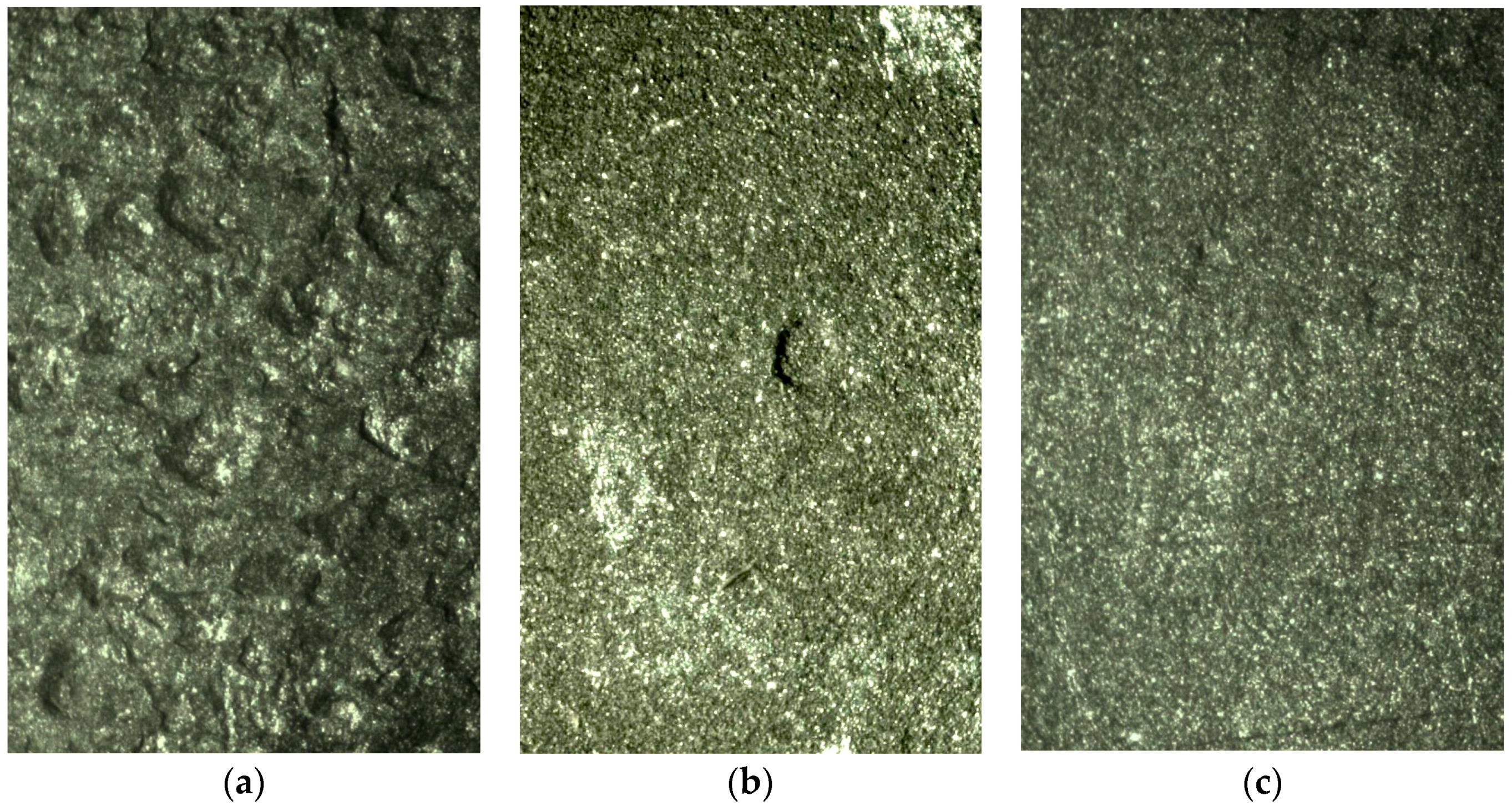
Irrespective of exposure condition and exposure time, when examined initially under a low magnification optical microscope (
i.e., ×10–×63), the coupons showed a remarkable differences in pitting and overall surface appearance between the steels. Steel A typically showed widespread very shallow pitting over its surfaces, measured subsequently to be typically around 30–50 microns in depth with a relatively small number of deeper pits (
Figure 2a). The number of pits that could be seen was estimated at around 200–250/cm
2, again independent of exposure water temperature or exposure duration. Steel B typically showed fewer pits (of shallow depth) and also fewer deeper pits (
Figure 2b). The overall pit density was estimated at around 30–40/cm
2 with some 10 deeper pits per side of coupon. For steel C (
Figure 2c), only very few deeper pits were observed—some 2–3 per side of coupon and these were less than 50 microns deep. Shallow pitting was less frequent and typically around 20–30 microns in depth. The depth of the pits was measured using a microscope with much higher magnification (see below).
The corroded surfaces were compared to corresponding images of coupons (blanks) that had not been exposed in order to ascertain the extent and severity of initial surface condition. The surfaces of coupons made from steel A showed some surface imperfections but, as noted, these are distinctly different in appearance from corrosion pits. For steels B and C the unexposed surfaces were remarkably free from surface imperfections (
Figure 2b,c).
As noted, the surfaces of the coupons were examined initially under a low magnification (×10–×63) optical microscope to identify the deepest pits. These were easily identified and differentiated from any surface imperfections, in part by geometry and in part because pits have bright-steel bases with characteristic patterns, as noted in earlier studies on the pitting of mild steels [
30]. These pits were marked and their depths measured relative to the surrounding metal surface using focus variation with the calibrated
z-axis of a conventional optical microscope (Zeiss Axio Imager A1m, Zeiss, Oberkochen, Germany). From these measurements the depth of the deepest pit and the average depth of the six deepest pits were obtained. In all cases, the overall metal surface used as the reference plane for pit depth was easily identified in the microscope image. Measurements were made also of the depth of the pits most frequently occurring on the metal surface. Random selection of such pits was made and the depths so measured showed remarkable consistency ([
30]). The number of pits per unit area was obtained by counting the number of visible pits of all sizes on areas visible under the low magnification optical microscope and estimating the visible area. Some of the coupon surfaces were polished and then examined by scanning electron microscope (SEM, Zeiss Sigma VP FESEM, Oberkochen, Germany) and energy dispersive spectroscopy (EDS, Bruker, Billerica, MA, USA), both before and after exposure. These examinations did not reveal anything unusual and, therefore, are not reported in detail.
Figure 3 shows a SEM image of a MnS inclusion (with typical elongated shape) and the corresponding EDS trace for the steel A with the lowest S content. Similar results were obtained for the lower inclusion and for steels B and C.
The corrosion and pit depth measurements and observations are summarized in
Table 2. The corrosion losses were obtained from the mass losses divided by the density of steel and the total surface area of the steel coupons, including coupon sides and ends and allowing for the presence of the fixing hole. Disregarding the side and the end areas produced slightly different results but the ratios of corrosion loss values are almost unchanged.
5. Discussion
The trends in
Figure 4 for maximum pit depth as a function of the C/S ratio of each steel are remarkably similar in character. In each case the estimated error involved is shown, taken here, conservatively, as the standard deviation for the average depth of the six deepest pits (
Table 2). The observations and the trends shown are the result of four separate experiments with independent exposures and with independent recovery of the respective coupons. Although there is some difference in the exact form of the trends, they all show that the depth of the deepest pit observed, and also that the average depth of the six deepest pits (
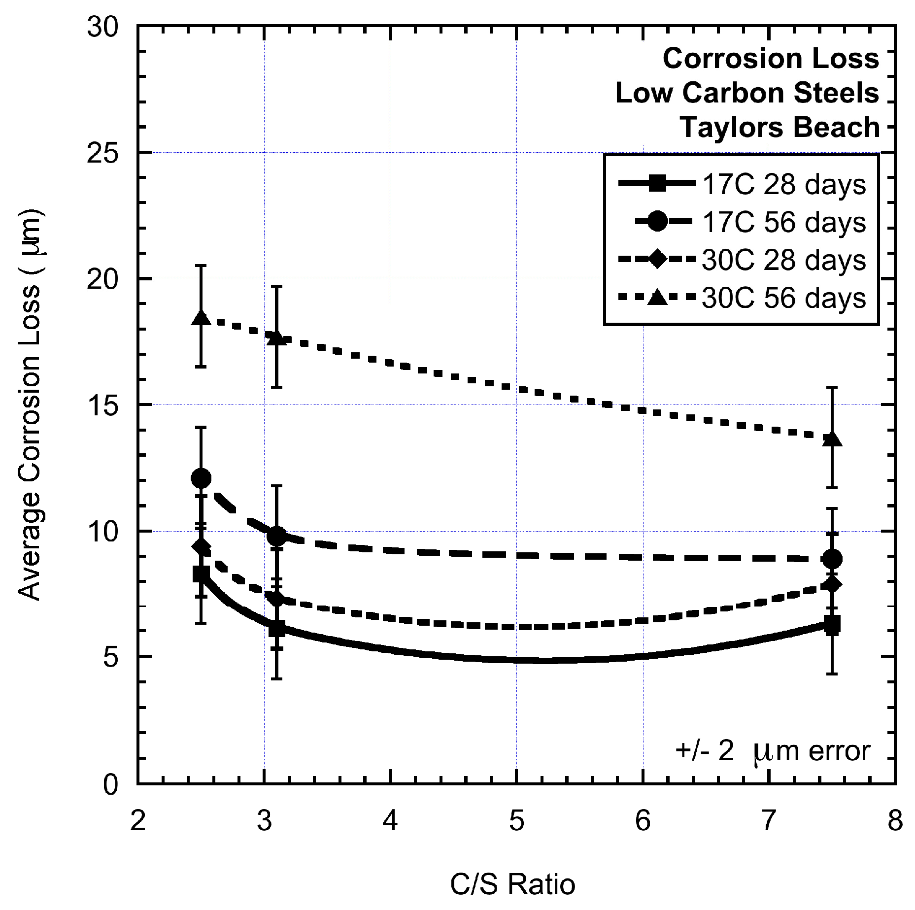
Table 2) decreases as the value of C/S increases. A similar, but less well-defined set of trends is shown in
Figure 5 for corrosion loss. As expected, the maximum pit depth and the average of the deepest pits as well as the overall corrosion loss increase with an increase in exposure time from 28 days to 56 days. However, the increment is lower than from zero to 28 days, again as would be expected from consistency with other observations showing gradually-reducing corrosion rates [
16]. Similarly, there is an increase in pit depth with increased temperature. Since the exposure conditions involved periods of stationary water it might be expected that both corrosion loss and pitting are lower than in fully agitated solutions—indeed this is the case, as can be seen when the present results are compared with corrosion losses and pitting in moving waters [
16].
Since C represents the iron carbide content of the steels and S represents the MnS content, each associated with the initiation of pitting, and each potentially resulting in a cathodic area for the respective initiated pits, the results can be interpreted as showing a first estimate of the effect of competing cathodic areas. Thus,
Figure 4 shows that for C standardized against S content, pitting becomes more severe for lower carbon content. A generally similar but less well-defined result holds for corrosion loss (
Figure 5). These results are consistent with the notion of competition for cathodic space, with cathodes for increased C content out-competing cathodes resulting from MnS inclusions.
A similar result holds when the Mn is in excess of that required to combine with S and when Cr is considered (
Table 2). Owing to the lack of detectable amounts of other inclusions such as Al and Si that often combine with Mn and Cr [
18,
31,
32], the respective oxides and silicates of Mn and Cr that may form are available to act as anodic areas. These also require associated cathodic areas for pitting corrosion to progress. As the content of other inclusions and iron carbide content increases, these may compete for space with cathodes from the more reactive MnS inclusions and the iron carbides. Overall, the experimental results do not support the conventional notion that increased S content increases pitting corrosion in the number of pits or in pit depth, or both, since in that case steel B, with the highest S content (0.013 wt. %) should have shown the most severe pitting and corrosion loss, followed by steel C (S = 0.008 wt. %), and then by A (S = 0.004 wt. %). The data shows that C content also is important. These observations are considered to support the cathode area competition model.
The potential influence of surface topography on the corrosion of low carbon steels warrants comment. A sufficiently good impression of the differences in surface topography, even after some short period of exposure, can be seen from the three surfaces shown in
Figure 2. The available experimental evidence shows that a rougher surface may advance pit initiation in time, and produce greater depth for early pitting but that, overall, the influence of surface topography is small and occurs mainly during the first week or so of exposure. For metal surfaces not acid cleaned or grit blasted, the change in mass loss is only a few percent even after six weeks of exposure [
40]. It follows that the differences in corrosion loss observed in the present experiments (
Table 2) cannot be the result of initial surface topography (imperfections). Conversely, it could have had a small effect on the depth of the deepest pits observed, particularly for steel A, since surface imperfections are known as possible initiators of pitting corrosion [
18,
21]. However, surface imperfections have not been implicated in the growth and eventual development of pit depth, which is the critical issue here. Hence, surface imperfections do not explain the differences in the observed maximum pit depths. This is illustrated, for example, by the relative pit depths for steels B and C, for which there was no noticeable difference in surface finish either at the macroscopic level or at the microscopic level.
The conceptual model proposed herein for the interaction between pits through competition between their cathodic regions considered to be a novel way of interpreting the role of cathodes in the corrosion process under natural exposure conditions. It is consistent with the well-established notion that the cathodic reaction is rate-controlling in the longer-term corrosion of metals, such as mild and low alloy steels [
3,
6], and there is increasing recognition of this for other metals [
41]. Importantly, this way of looking at the pitting process and its interaction with longer-term mass loss opens up the possibility for interpreting other observations, some of which have not previously been given completely satisfactory explanations.
Probably the most intriguing possibility to arise from the concept proposed herein is that the MnS inclusions considered by Wranglen [
5] to show more activity could be those few MnS inclusions that are not blanketed by cathodic regions from other pits, irrespective of whether these arise from iron carbides, from MnS inclusions, or from other inclusions. The so-called active MnS inclusions would, thus, be those with activity associated with the electrochemical potential for MnS inclusions within a ferrous matrix and the other, less active, inclusions would be those influenced by cathodes of other pits. Such an explanation would be consistent with Wranglen’s observations and with the preliminary experimental results given herein.
The concept proposed above also would allow explanation of Wranglen’s observation [
7] that heat treatment and annealing of steels, which is known to reduce the grain size [
18], appears to reduce the presence of active MnS inclusions. Heat treatment also causes a reduction in the size of MnS inclusions [
42] and more of them per unit volume of metal for given content of S. The same would apply to other inclusions, and possibly also to iron carbides. However, the electrochemical potential for pitting associated with each would remain the same. Proportionally more anodes and cathodes would try to form, creating a more crowded situation and a greater probability of pit activity being blanketed by the cathodes of adjacent pits. In effect, there is a lower probability of a MnS inclusion remaining unaffected by any neighbouring pits and their cathodic regions. As a result there should be a reduction in severity of occurrence of pitting.
It should be clear that the idea of competition proposed here for cathodic regions has support from fundamental notions in corrosion science and also, to some extent, from the limited experiments reported herein. Clearly, considerable scope exists for further and more detailed investigations, most likely involving much more detailed experimental techniques, not available in the present study, including nanoscale imaging analyses and spectral resolution, as well refinements of the preliminary experiments reported herein.


