
Application of Boron Oxide as a Protective Surface Treatment to Decrease the Air Reactivity of Carbon Anodes

Abstract
:1. Introduction
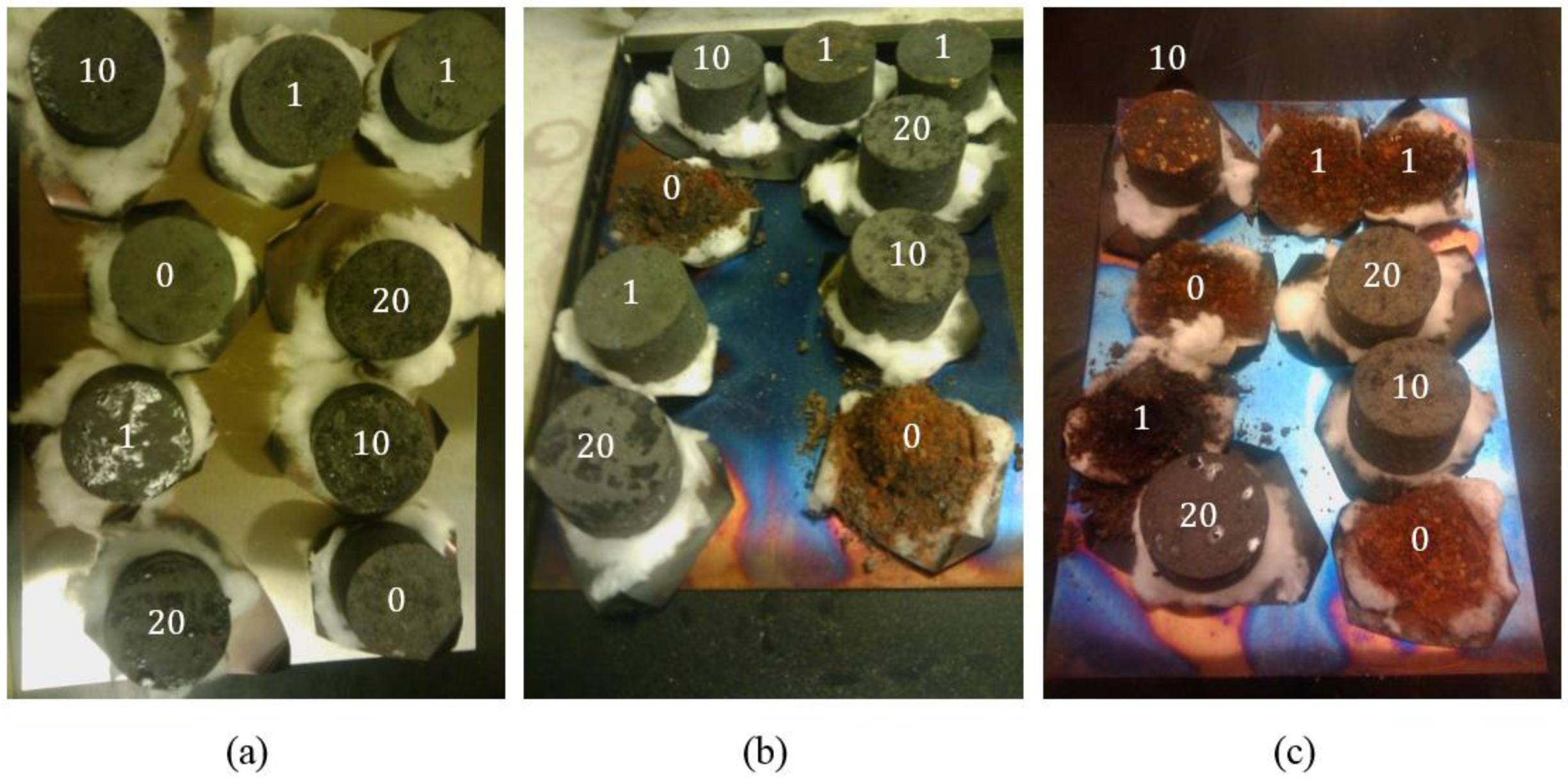
- (a)
- (b)
- (c)
- (1)
- In most experimental works conducted on composite materials reinforced by carbon fiber, the boron addition level is too high (from 1000 ppm up to several at. %) [24]. This high level of boron addition is not allowed in the anode, keeping in mind that all boron will most likely reduce in the bath and enter the aluminum.
- (2)
- The change in electron density is basically due to the fact that boron is substituted in the graphite structure. Since the anode baking temperature is much lower than the graphitization temperature, no significant graphitization occurs during baking. Thus, the boron effect on carbon graphitization is not conceivable.
- (3)
- In boron-doped graphite, boron is always added in the form of elemental boron under inert atmosphere prior to graphitization. Considering the cost of elemental boron, such a high level of addition is justified only for very high-value products, which is not the case for carbon anodes.
2. Materials and Methods
2.1. Materials
2.2. Air Reactivity Tests
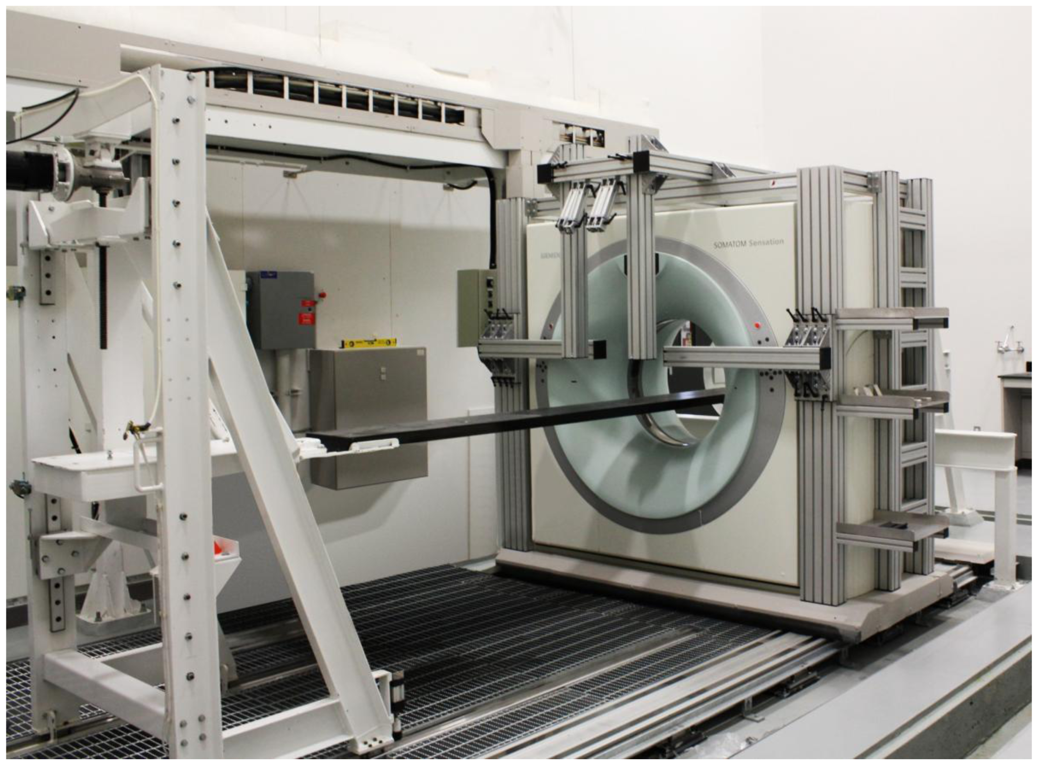
2.3. X-ray Computed Tomography
3. Results and Discussion
3.1. Anode Impregnation
3.2. Effect of Impregnation Time
3.3. Boron Loading during Impregnation
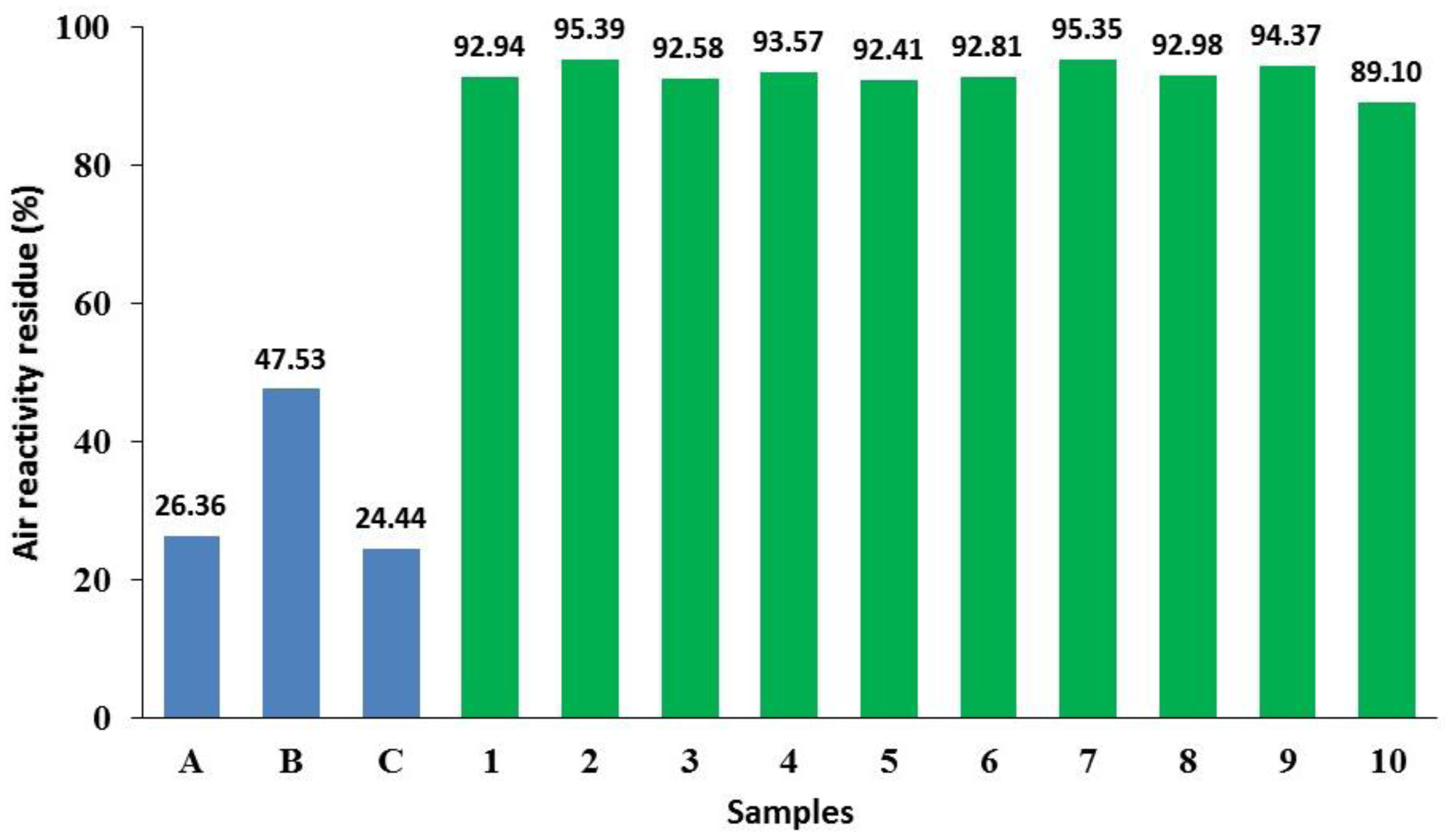
- (1)
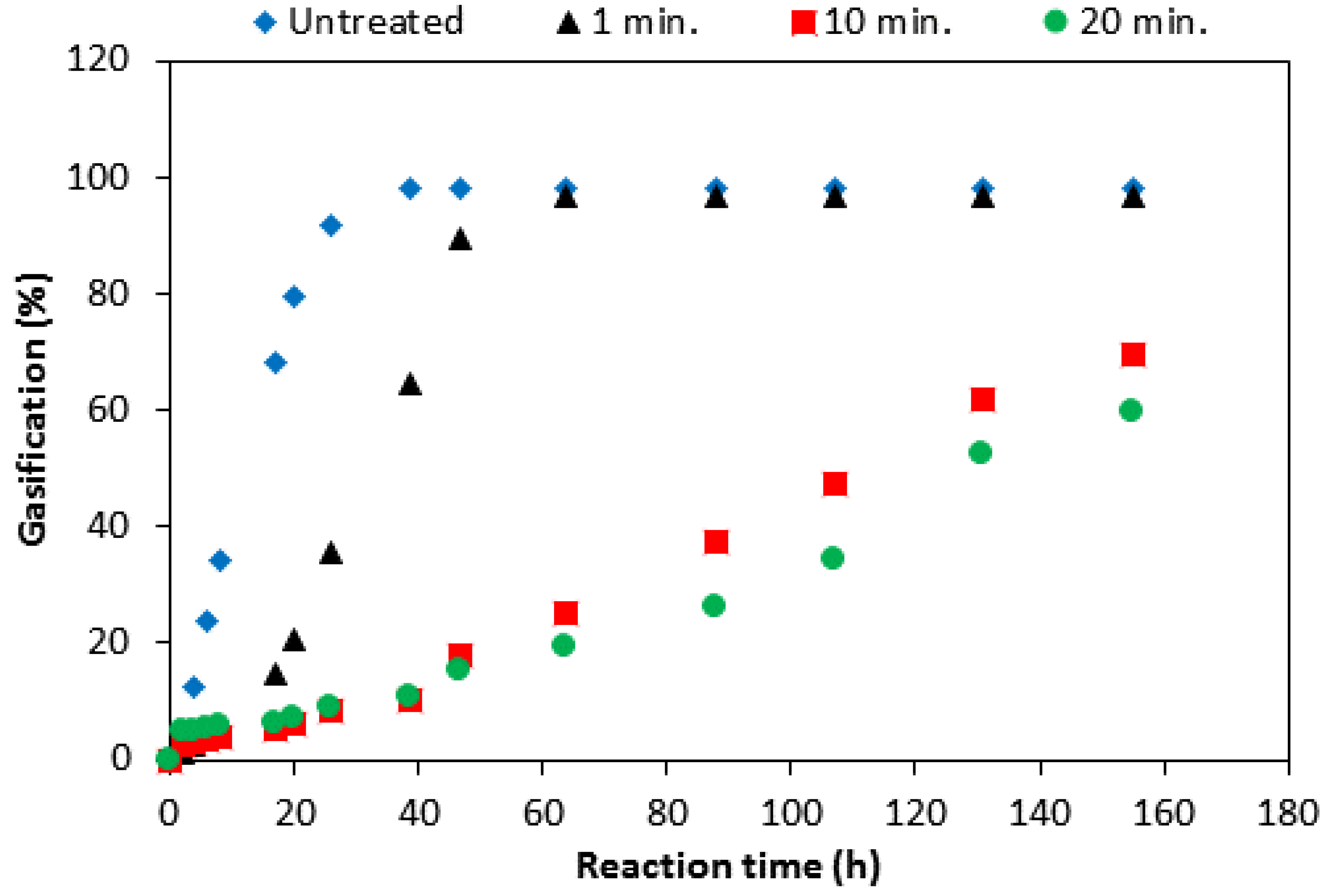
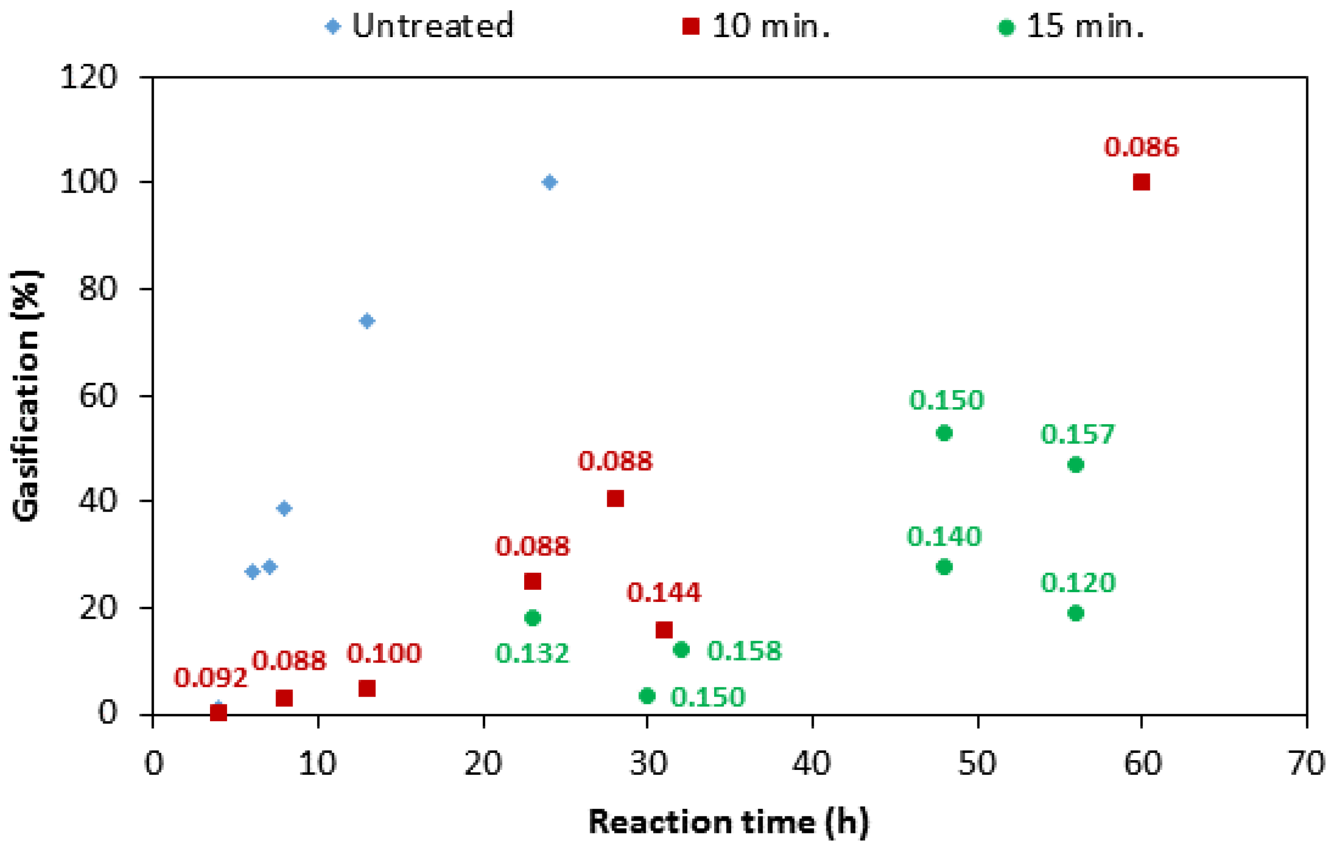
- The boron loading for a given impregnation time is different from one sample to another, ranging from 0.072 to 0.144 g for 10-min of impregnation and 0.074–0.157 g for 15 min of impregnation. The variation could be attributed to the different levels of porosity in the samples. This observation may explain the large variation in the reactivity of the samples, as observed for samples 10 and 20 in Figure 5, exhibiting different reactivity, in spite of the same impregnation time. Strictly speaking, this observation confirms that the boron loading could be different even if the impregnation conditions are the same.
- (2)
- The average value of boron loading on two sets of samples (9–16 and 17–27) increased from 0.09 g to 0.13 g, respectively. This suggests that the average boron loading increases significantly by increasing the impregnation time.
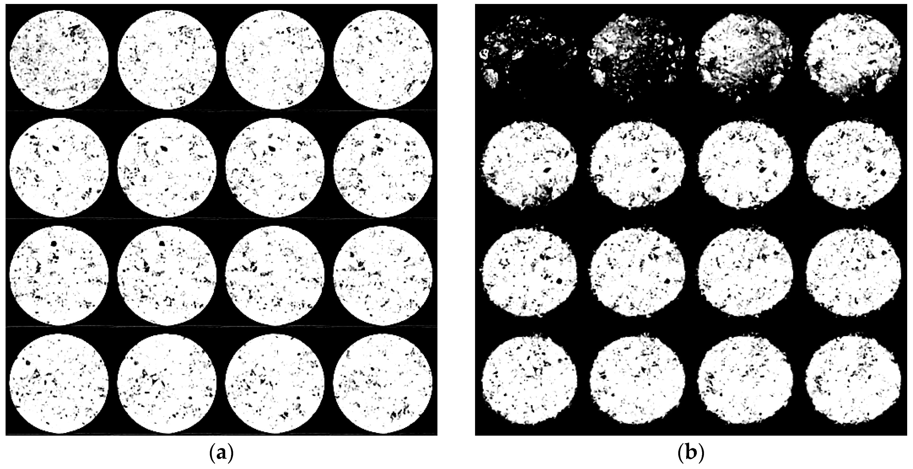
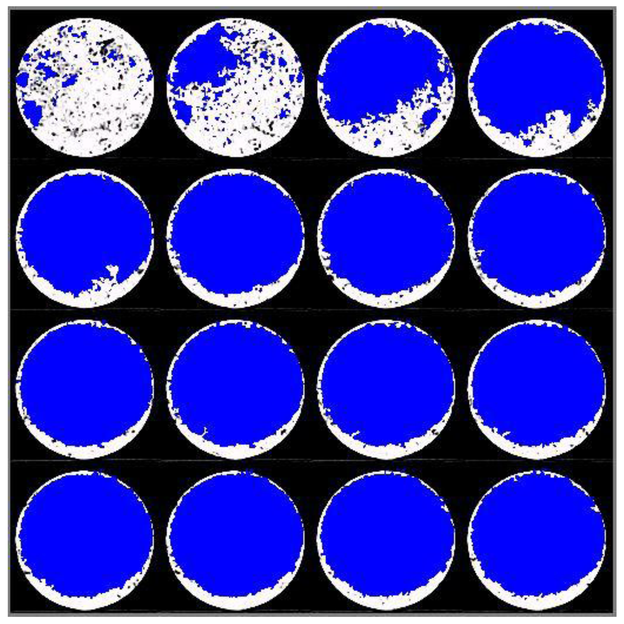
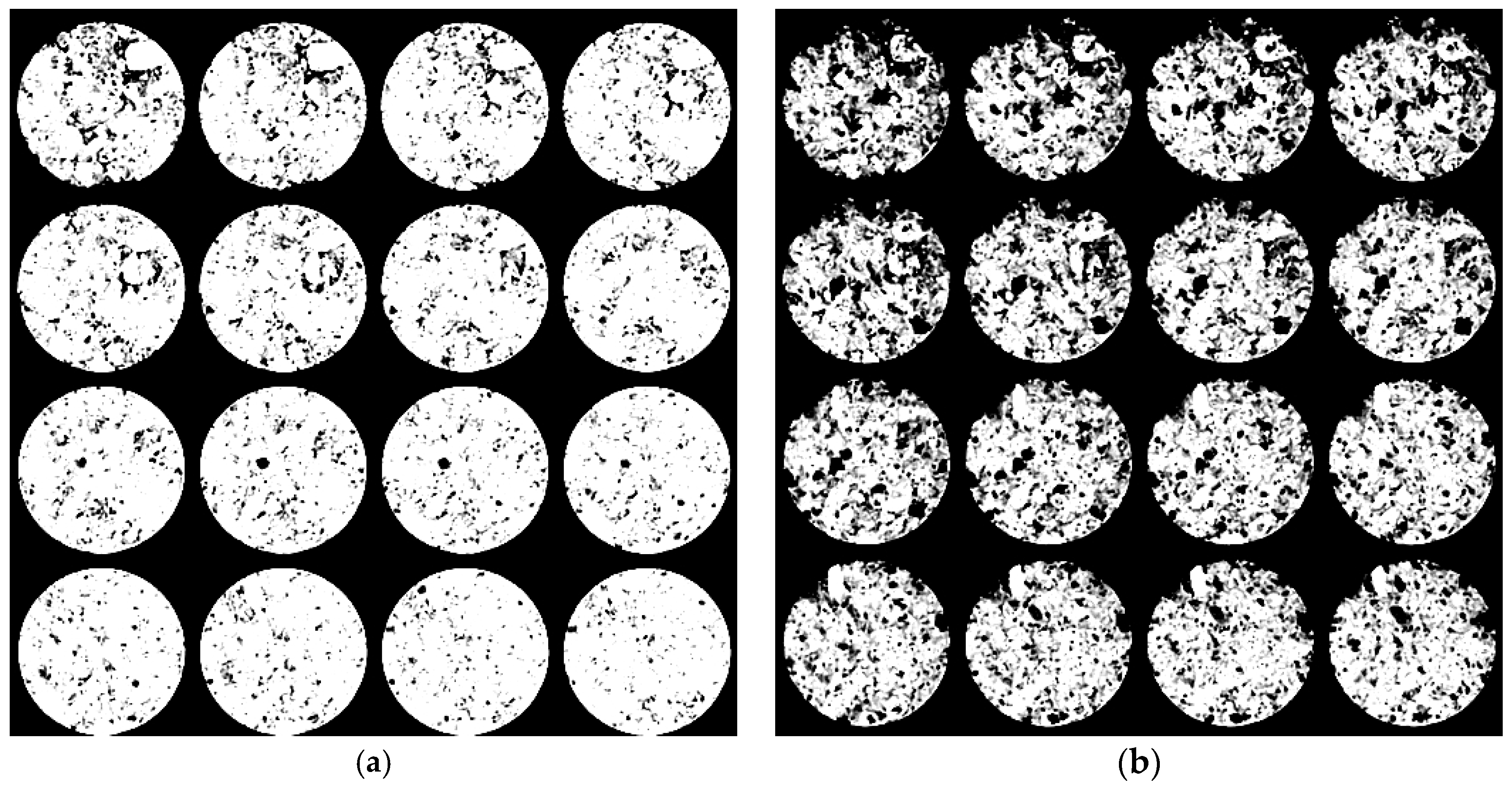
3.4. Effect of Boron-Coating on the Anode Reaction Mode
- (1)
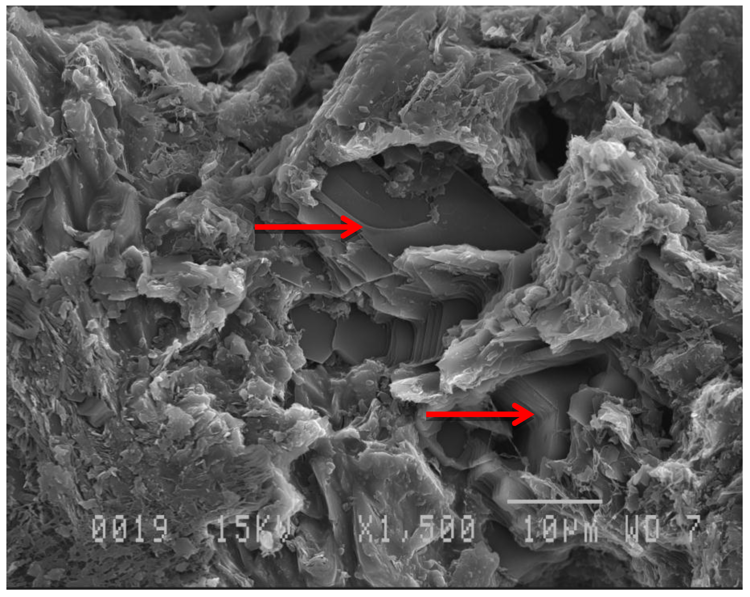
- The impregnation solution reaches the entire pore network and provides a good protection even inside the sample.
- (2)
- For the impregnated samples the reaction rate is very slow, so that the reaction will not be limited by diffusion. For the un-impregnated sample, however, diffusion limitation leads to consumption of only the outer surface.
4. Conclusions
Acknowledgments
Author Contributions
Conflicts of Interest
References
- Srinivasan, S.; Bommaraju, T. Electrochemical Technologies and Applications. In Fuel Cells: From Fundamentals to Applications; Springer: New York, NY, USA, 2006; pp. 98–186. [Google Scholar]
- Fischer, W.K.; Perruchoud, R.C. Factors influencing the carboxy- and air-reactivity behavior of prebaked anodes in hall-heroult cells. In Proceedings of the Light Metals 1986—TMS 1986: 115th Annual Meeting, New Orleans, LA, USA, 2–6 March 1986; Minerals, Metals and Materials Society: New Orleans, LA, USA, 1986; pp. 575–580. [Google Scholar]
- Keller, F.; Mannweiler, U.; Knall, E. Anode for the aluminum industry. In Constructing and Operating Anode Plants: What Top Management Needs to Know; R & D Carbon Ltd.: Sierre, Switzerland, 1995; pp. 217–224. [Google Scholar]
- Eidet, T. Reactions on Carbon Anodes in Aluminium Electrolysis. Ph.D. Thesis, Norwegian University of Science and Technology, Trondheim, Norway, October 1997. [Google Scholar]
- Vitchus, B.; Cannova, F. Pratical air reactivity impacts on anode performance. In Proceedings of the Light Metals 2002—TMS 2002: 131st TMS Annual Meeting, Seattle, WA, USA, 17–21 February 2002; Minerals, Metals and Materials Society: Seattle, WA, USA, 2002; pp. 553–559. [Google Scholar]
- Lustenberger, M. Heat treatment of anodes for the Aluminium Industry. In Institut des Matériaux; Faculté Sciences et Techniques de l’Ingénieur: Lausanne, Switzerland, 2004; p. 143. [Google Scholar]
- Bensah, Y.D.; Foosnaes, T. The Nature and Effect of Sulphur Compounds on CO2 and Air Reactivity of Petrol Coke. ARPN J. Eng. Appl. Sci. 2010, 5, 35–43. [Google Scholar]
- Sørlie, M.; Eidet, T. The influence of pitch impurity content on reactivity of binder coke. In Proceedings of the Light Metals 1998—TMS 1998: 127th Annual Meeting and Exhibition, San Antonio, TX, USA, 15–19 February 1998; Minerals, Metals and Materials Society: San Antonio, TX, USA, 1998; pp. 763–768. [Google Scholar]
- Farr-Wharton, R.; Welch, B.J. Chemical and electrochemical oxidation of heterogeneous carbon anodes. Electrochim. Acta 1980, 25, 217–221. [Google Scholar] [CrossRef]
- Tordai, T. Anode dusting during the electrolytic production of aluminum. In Falculté des Sicences et Techniques des Matériaux; Ecole Polytechnique Fédérale de Lausanne: Lausanne, Switzerland, 2007; p. 331. [Google Scholar]
- Rolofs, B.; Poi, N.W. The effect of anode spike formation on operational performance. In Proceedings of the Light Metals 2000—TMS 2000: 129th TMS Annual Meeting TMS Annual Meeting, Nashville, TN, USA, 12–16 March 2000; Minerals, Metals and Materials Society: Nashville, TN, USA, 2000; pp. 535–540. [Google Scholar]
- Gudmundsson, H. Anode dusting from a potroom perpective at nordural and correlation with anode properties. In Proceedings of the Light Metals 2011—TMS 2011: 141th Annual Meeting and Exhibition, San Diego, CA, USA, 27 February–3 March 2011; Minerals, Metals and Materials Society: San Diego, CA, USA, 2011; pp. 471–476. [Google Scholar]
- Jahedi, M.; Oh, A.; Gulizia, E.; Gulizia, S.; Mallah, A.J. Anode coating to prevent airburn in aluminium smelters. In Proceedings of the Light Metals 2009—TMS 2009: 138th Annual Meeting and Exhibition, San Francisco, CA, USA, 15–19 February 2009; Minerals, Metals and Materials Society: San Francisco, CA, USA, 2009; pp. 951–955. [Google Scholar]
- Lee, Y.J.; Radovic, L.R. Oxidation inhibition effects of phosphorus and boron in different carbon fibrics. Carbon 2003, 41, 1987–1997. [Google Scholar] [CrossRef]
- Durkic, T.; Peric, A.; Lausevic, M.; Dekanski, A.; Neskovic, O.; Veljkovic, M.; Lausevic, Z. Boron and phosphorus doped glassy carbon: I. Surface propertie. Carbon 1997, 35, 1567–1572. [Google Scholar] [CrossRef]
- Kowbel, W.; Huang, Y.; Tsou, H. Effect of boron ion implantation on the oxidation behaviour of three-dimensional carbon-carbon composite. Carbon 1993, 31, 355–363. [Google Scholar] [CrossRef]
- Radovic, L.R.; Karra, M.; Skokova, K.; Thrower, P.A. The role of substitutional boron in carbon oxidation. Carbon 1998, 36, 1841–1854. [Google Scholar] [CrossRef]
- Howe, J.Y.; Jones, L.E. Influence of boron on structure and oxidation behaviour of graphite fiber, P120. Carbon 2004, 42, 461–467. [Google Scholar] [CrossRef]
- Zhong, D.H.; Sano, H.; Uchiyama, Y.; Kobayashi, K. Effect of low-level boron doping on oxidation behaviour of polymide-derived carbon films. Carbon 2000, 38, 1199–1206. [Google Scholar] [CrossRef]
- Hagio, T.; Nakamizo, M.; Kobayashi, K. Studies on X-ray diffracton and Raman sectra of B-doped natural graphite. Carbon 1989, 27, 259–263. [Google Scholar] [CrossRef]
- Xianxian, W.; Radovic, L.R. Inhibition of catalytic oxidation of carbon/carbon composites by boron-doping. Carbon 2005, 43, 1768–1777. [Google Scholar]
- Jonse, L.E.; Thrower, P.A. Influence of boron on carbon fiber microstructure, physical properties and oxidation behaviour. Carbon 1991, 29, 251–269. [Google Scholar] [CrossRef]
- Jonse, L.E.; Thrower, P.A. The effect of boron on carbon-fiber microstructure and reactivity. J. Chim. Phys. Phys. Chim. Biol. 1987, 84, 1431–1438. [Google Scholar]
- Sogabe, T.; Nakajima, K.; Inagaki, M. Effect of boron-doping on structure and some properties of carbon-carbon composite. J. Mater. Sci. 1996, 31, 6469–6476. [Google Scholar] [CrossRef]
- Manganiello, F.; Duruz, J.-J.; Bello, V. Treating Prebaked Carbon Components for Aluminum Production, The Treated Components Thereof, and the Components Use in an Electrolytic Cell. U.S. Patent 5,486,278, 28 March 1994. [Google Scholar]
- Sekhar, J.A.; Liu, J.J.; Duruz, J.-J. Carbon Bodies Resistant to Deterioration by Oxidizing Gases. U.S. Patent 5,753,382, 10 January 1996. [Google Scholar]
- Sekhar, J.A.; Liu, J.J.; Duruz, J.-J. Carbon Bodies Resistant to Deterioration by Oxidizing Gases. U.S. Patent 5,985,114, 15 September 1997. [Google Scholar]
- Bello, V.A.; Duruz, J.-J.; Manganiello, F.A. Treating Prebaked Carbon Anodes for Aluminium Production. European Patent 0,701,635, 1 June 1994. [Google Scholar]
- Tosta, M.R.J.; Inzunza, E.M.; Delgado, L.A. Boron salt inhibitors of air reactivity of prebaked carbon anodes—Literature review and laboratory study. In Proceedings of the Light Metals 2009—TMS 2009: 138th Annual Meeting and Exhibition, San Francisco, CA, USA, 15–19 February 2009; Minerals, Metals and Materials Society: San Francisco, CA, USA, 2009; pp. 1173–1176. [Google Scholar]
- Mirtchi, A.A.; Bergeron, J. Method for Providing a Protective Coating for Carbonaceous Components of An Electrolysis Cell. U.S. Patent 6,475,358, 6 February 2001. [Google Scholar]
- Babaei, F.; Hong, T.L.C.; Yeung, K.; Cheng, S.H.; Lam, Y.W. Contrast-enhanced X-ray micro-computed tomography as a versatile method for anatomical studies of adult zebrafish. Zebrafish 2016, 13, 310–316. [Google Scholar] [CrossRef] [PubMed]
- Cnudde, V.; Boone, M.N. High-resolution X-ray computed tomography in geosciences: A review of the current technology and applications. Earth Sci. Rev. 2013, 123, 1–17. [Google Scholar] [CrossRef]
- Helliwell, J.R.; Sturrock, C.J.; Grayling, K.M.; Tracy, S.R.; Flavel, R.J.; Young, I.M.; Whalley, W.R.; Mooney, S.J. Applications of X-ray computed tomography for examining biophysical interactions and structural development in soil systems: A review. Eur. J. Soil Sci. 2013, 64, 279–297. [Google Scholar] [CrossRef]
- Mazonakis, M.; Damilakis, J. Computed tomography: What and how does it measure? Eur. J. Radiol. 2016, 85, 1499–1504. [Google Scholar] [CrossRef] [PubMed]
- Adams, A.N.; Karacan, O.; Grader, A.; Mathews, J.P.; Halleck, P.M.; Schobert, H.H. The non-destructive 3-D characterization of pre-baked carbon anodes using X-ray computerized tomography. In Proceedings of the Light Metals 2002—TMS 2002: 131st TMS Annual Meeting, Seattle, WA, USA, 17–21 February 2002; Minerals, Metals and Materials Society: Seattle, WA, USA, 2002; pp. 535–539. [Google Scholar]
- Sommerseth, C.; Thorne, R.J.; Rørvik, S.; Sandnes, E.; Ratvik, A.P.; Lossius, L.P.; Linga, H.; Svensson, A.M. Spatial methods for characterising carbon anodes for aluminium production. In Proceedings of the Light Metals 2015—TMS 2015: 144th Annual Meeting and Exhibition, Orlando, FL, USA, 15–19 March 2015; Minerals, Metals and Materials Society: Orlando, FL, USA, 2015; pp. 1141–1146. [Google Scholar]
- Picard, D.; Alamdari, H.; Ziegler, D.; Dumas, B.; Fafard, M. Characterization of prebaked carbon anode samples using X-ray computed tomography and porosity estimation. In Proceedings of the Light Metals 2012—TMS 2012: 141st Annual Meeting and Exhibition, Orlando, FL, USA, 11–15 March 2012; Minerals, Metals and Materials Society: Orlando, FL, USA, 2012; pp. 1283–1288. [Google Scholar]
- Azari, K.; Alamdari, H.; Aryanpour, G.; Picard, D.; Fafard, M.; Adams, A. Mixing variables for prebaked anodes used in aluminum production. Powder Technol. 2013, 235, 341–348. [Google Scholar] [CrossRef]
- Suriyapraphadilok, U.; Halleck, P.; Grader, A.; Andresen, J.M. Physical, chemical and X-ray computed tomography characterization of anode butt cores. In Proceedings of the Light Metals 2005—TMS 2005: 134th TMS Annual Meeting, San Francisco, CA, USA, 13–17 February 2005; Minerals, Metals and Materials Society: San Francisco, CA, USA, 2005; pp. 617–621. [Google Scholar]


| Sample | Solute Mass (g) | Solvent | Solvent Volume (mL) | Concentration (g/mL) | Solution Temperature |
|---|---|---|---|---|---|
| A | Untreated | - | - | - | - |
| B | Untreated | - | - | - | - |
| C | Untreated | - | - | - | - |
| 1 | 9 | Water | 50 | 0.180 | Boiling |
| 2 | 1 | Water | 50 | 0.020 | R. temp |
| 3 | 9.08 | Water | 50 | 0.182 | Boiling |
| 4 | 1 | Water | 50 | 0.020 | R. temp |
| 5 | 1 | Water | 50 | 0.020 | R. temp |
| 6 | 8.98 | Water | 50 | 0.180 | Boiling |
| 7 | 9.03 | Water | 50 | 0.181 | Boiling |
| 8 | 9.08 | Water | 50 | 0.182 | Boiling |
| 9 | 9.03 | Water | 50 | 0.181 | Boiling |
| 10 | 1.05 | Water | 50 | 0.021 | R. temp |
| Sample | Solute Mass (g) | Solvent | Solvent Volume (mL) | Concentration (g/mL) | Solution Temperature |
|---|---|---|---|---|---|
| 1 | 9.06 | Water | 50 | 0.181 | Boiling |
| 2 | 1.02 | Water | 50 | 0.020 | R. temp |
| 3 | 9.06 | Water | 50 | 0.181 | Boiling |
| 4 | 1.03 | Water | 50 | 0.020 | R. temp |
| 6 | 8.94 | Water | 50 | 0.179 | Boiling |
| Sample | Solute Mass (g) | Solvent | Solvent Volume (mL) | Concentration (g/mL) | Solution Temperature | Dipping Time (min) |
|---|---|---|---|---|---|---|
| 1 | Untreated | - | - | - | - | - |
| 2 | Untreated | - | - | - | - | - |
| 3 | 53.49 | Water | 300 | 0.178 | Boiling | 1 |
| 4 | 53.49 | Water | 300 | 0.178 | R. temp | 10 |
| 5 | 48.08 | Water | 265 | 0.181 | Boiling | 1 |
| 6 | 48.08 | Water | 265 | 0.181 | R. temp | 10 |
| 7 | 35.87 | Water | 200 | 0.179 | R. temp | 20 |
| 8 | 36.19 | Water | 200 | 0.181 | Boiling | 20 |
| Sample | Dry Sample (g) | Beaker + Solution (g) | Solution in Sample (g) | B2O3 Loading (g) | Dipping Time (min) |
|---|---|---|---|---|---|
| - | - | 701.0 | - | - | - |
| 9 | 74.2537 | 693.8 | 7.2 | 0.144 | 1 |
| 10 | 79.8949 | 689.4 | 4.4 | 0.088 | 1 |
| 11 | 76.9634 | 685.0 | 4.4 | 0.088 | 1 |
| 12 | 75.5964 | 679.9 | 5.1 | 0.102 | 1 |
| 13 | 75.3947 | 675.6 | 4.3 | 0.086 | 1 |
| 14 | 71.5214 | 671.2 | 4.4 | 0.088 | 1 |
| 15 | 74.0581 | 666.6 | 4.6 | 0.092 | 1 |
| 16 | 78.2129 | 663.0 | 3.6 | 0.072 | 1 |
| - | - | 682.0 | - | - | - |
| 17 | 78.3638 | 678.3 | 3.7 | 0.074 | 15 |
| 18 | 79.0604 | 670.5 | 7.8 | 0.156 | 15 |
| 19 | 62.7609 | 664.0 | 6.5 | 0.130 | 15 |
| 20 | 64.5848 | 657.4 | 6.6 | 0.132 | 15 |
| 21 | 59.4021 | 651.4 | 6 | 0.120 | 15 |
| 22 | 61.6083 | 643.8 | 7.6 | 0.152 | 15 |
| 23 | 61.8290 | 637.8 | 6.0 | 0.120 | 15 |
| 24 | 61.5569 | 630.3 | 7.5 | 0.150 | 15 |
| 25 | 68.1607 | 623.3 | 7 | 0.140 | 15 |
| 26 | 75.3353 | 615.4 | 7.9 | 0.158 | 15 |
| 27 | 74.0279 | 609.0 | 6.4 | 0.128 | 15 |
© 2017 by the authors. Licensee MDPI, Basel, Switzerland. This article is an open access article distributed under the terms and conditions of the Creative Commons Attribution (CC BY) license ( http://creativecommons.org/licenses/by/4.0/).
Share and Cite
Ishak, R.; Picard, D.; Laroche, G.; Ziegler, D.P.; Alamdari, H. Application of Boron Oxide as a Protective Surface Treatment to Decrease the Air Reactivity of Carbon Anodes. Metals 2017, 7, 79. https://doi.org/10.3390/met7030079
Ishak R, Picard D, Laroche G, Ziegler DP, Alamdari H. Application of Boron Oxide as a Protective Surface Treatment to Decrease the Air Reactivity of Carbon Anodes. Metals. 2017; 7(3):79. https://doi.org/10.3390/met7030079
Chicago/Turabian StyleIshak, Ramzi, Donald Picard, Gaétan Laroche, Donald P. Ziegler, and Houshang Alamdari. 2017. "Application of Boron Oxide as a Protective Surface Treatment to Decrease the Air Reactivity of Carbon Anodes" Metals 7, no. 3: 79. https://doi.org/10.3390/met7030079