Article

New Low-Sn Zr Cladding Alloys with Excellent Autoclave Corrosion Resistance and High Strength

1
Science and Technology on Reactor Fuel and Materials Laboratory, Nuclear Power Institute of China, Chengdu 610213, China
2
Key Laboratory of Materials Modification by Laser, Ion and Electron Beams (Ministry of Education), School of Materials Science and Engineering, Dalian University of Technology, Dalian 116024, China
*
Author to whom correspondence should be addressed.
Metals 2017, 7(4), 144; https://doi.org/10.3390/met7040144
Submission received: 21 March 2017 / Revised: 12 April 2017 / Accepted: 17 April 2017 / Published: 19 April 2017
(This article belongs to the Special Issue Zirconium Alloys)

Abstract

:
It is expected that low-Sn Zr alloys are a good candidate to improve the corrosion resistance of Zr cladding alloys in nuclear reactors, presenting excellent corrosion resistance and high strength. The present work developed a new alloy series of Zr-0.25Sn-0.36Fe-0.11Cr-xNb (x = 0.4~1.2 wt %) to investigate the effect of Nb on autoclave corrosion resistance. Alloy ingots were prepared by non-consumable arc-melting, solid-solutioned, and then rolled into thin plates with a thickness of 0.7 mm. It was found that the designed low-Sn Zr alloys exhibit excellent corrosion resistances in three out of pile autoclave environments (distilled water at 633 K/18.6 MPa, 70 ppm LiOH solution at 633 K/18.6 MPa, and superheated water steam at 673 K/10.3 MPa), as demonstrated by the fact of the Zr-0.25Sn-0.36Fe-0.11Cr-0.6Nb alloy shows a corrosion weight gain ΔG = 46.3 mg/dm2 and a tensile strength of σUTS = 461 MPa following 100 days of exposure in water steam. The strength of the low-Sn Zr alloy with a higher Nb content (x = 1.2 wt %) is enhanced up to 499 MPa, comparable to that of the reference high-Sn N36 alloy (Zr-1.0Sn-1.0Nb-0.25Fe, wt %). Although the strength improvement is at a slight expense of corrosion resistance with the increase of Nb, the corrosion resistance of the high-Nb alloy with x = 1.2 (ΔG = 90.4 mg/dm2 for 100-day exposure in the water steam) is still better than that of N36 (ΔG = 103.4 mg/dm2).

1. Introduction

As fuel cladding and structural materials for commercial nuclear reactors, Zr alloys exhibit excellent radiation-resistance and good corrosion-resistance and mechanical properties in a neutron reactor environment lower than 623 K [1,2,3]. Such alloys with high performance were the main focus in Zr-Sn and Zr-Nb series [4,5,6,7,8,9,10], e.g., Zr-1.0Sn-1.0Nb-0.1Fe (ZIRLO alloy, the number before each element represents the weight percent, wt %), Zr-1.0Nb-O (M5), Zr-1.2Sn-1.0Nb-0.35Fe (E635), and Zr-1.0Sn-1.0Nb-0.25Fe (N36). They were generally minor-alloyed with multiple solute elements to achieve the optimum comprehensive properties. In order to further improve the waterside corrosion resistance, several Zr alloys with a much lower content of Sn were expected to be developed, such as Zr-0.4Sn-0.2Fe-0.1Cr-1.5Nb (HANA-4) [1] and Zr-0.66Sn-1.0Nb-0.1Fe, modified from ZIRLO alloy [11].
It is emphasized that the mechanical strength and the corrosion resistance of Zr alloys are closely related to the types and amounts of alloying elements [12,13,14,15,16,17]. It is difficult to achieve high strength and excellent corrosion resistance simultaneously through adding one or two elements since these two requirements are incompatible. For instance, the element Sn promotes the solid-solution strengthening, while its excessive content could deteriorate the corrosion resistance [3,11]. Fe, Cr, and Nb elements are always precipitated from the α-Zr matrix to form the second phases, such as Zr(Fe,Cr)2 and β-Nb, which can enhance the mechanical properties of alloys at the expense of the corrosion resistance [4,5,6,7,8,9,10,18,19,20,21,22,23]. Actually, different Fe/Cr ratios in the Zr(Fe,Cr)2 phase can also induce different corrosion resistance in the Fe/Cr-containing Zr alloys [5]. Thus, for low-Sn Zr alloys, the contents of other alloying elements should be adjusted to ensure the mechanical properties, as demonstrated by the fact that increasing the Fe content indeed enhances the strengths of Zr-1.0Nb-xFe alloy series [24].
By far, the mechanical and autoclave corrosion-resistant properties of Zr alloys with a much lower Sn content have been seldom reported. Therefore, the present work will aim at developing a new low-Sn Zr alloy series of Zr-0.25Sn-0.36Fe-0.11Cr-xNb, in which the Nb content is varied and the Fe and Cr contents are fixed and referred from the present in-pile N18 alloy (Zr-1.0Sn-0.35Fe-0.11Cr-0.35Nb) due to the suitable Fe/Cr ratio [5]. The microstructural characterization, tensile mechanical property, and autoclave corrosion resistances in three corrosive mediums of the designed alloy series will be performed comprehensively to evaluate the effect of Nb element on the properties. The high-Sn N36 alloy (Zr-1.0Sn-0.25Fe-1.0Nb) with a higher strength and good corrosion resistance is taken here as the reference alloy. It would be verified that this series of new low-Sn Zr alloys will possess prominent autoclave corrosion resistances and high strengths.

2. Experimental Section

The alloy ingots of the designed low-Sn alloy series of Zr-0.25Sn-0.36Fe-0.11Cr-xNb (x = 0.4, 0.6, 0.8, and 1.2, called Z-xNb hereafter), as well as the reference N36, were prepared by non-consumably arc-melting the mixtures of Zr, Fe, Cr, Sn, and Nb with a purity of 99.99% in the Ti-gettered high-purity argon atmosphere. These ingots with a weight of about 50 g were flipped and remelted at least five times to ensure chemical homogeneity. They were then solid-solutioned at 1323 K for 0.5 h under a vacuum condition plus water-quenching. In the following, all the ingots were hot rolled into plates a thickness of 2 mm at 873 K eight times, in which the surface of the plates was cut mechanically for the deletion of the oxidation layer. Alloy plates were resealed into a vacuum quartz cube for further heat-treatment at 853 K for 1 h and then cold-rolled into thin plates with a thickness of 0.7 mm three times. Finally, these thin plates were heat-treated at 833 K for 2 h under a vacuum condition. All the heat treatments and rolling processing were taken from those for the reference N36 alloy.
Structural identification was performed by the Bruker D8 Focus X-ray diffraction (XRD, Ettlingen, Germany) using the Cu Kα radiation (λ = 0.15406 nm), in which the Jade software was used to fit the diffraction peaks [25]. The microstructure morphology and phase verification were carried on with the Philips Tecnai G2 transmission electron microscopy (TEM, Amsterdam, the Netherlands) with the selected-area electron diffraction (SAED) analysis, where the TEM samples were prepared by twin-jet electro-polishing in a solution of 12% HClO4 + 88% C2H5OH (volume fraction) at 243 K. Tensile tests were performed at room temperature with a strain rate of 3.5 × 10⁻⁴ s−1 by using a MTS-810 tensile testing machine (MTS, Cary, NC, USA). The tensile specimens were machined along the rolling direction with a gauge size of 24 × 4 mm (length × width), in which four tensile specimens were prepared for each composition alloy. The autoclave corrosion tests were conducted under three out-of-pile conditions, i.e., distilled water at 633 K with a pressure of 18.6 MPa, 70 ppm LiOH aqueous solution at 633 K with a pressure of 18.6 MPa, and superheated water steam at 673 K with a pressure of 10.3 MPa, respectively. The specimens for corrosion testing are rectangular with a size of 20 × 30 mm and three specimens for each alloy under each condition were prepared, in which the sample surfaces were ground to 1200-grit SiC paper. The corrosion resistance of the specimens was evaluated by measuring the weight gain per unit surface area in relation to the exposure time.

3. Results and Discussion

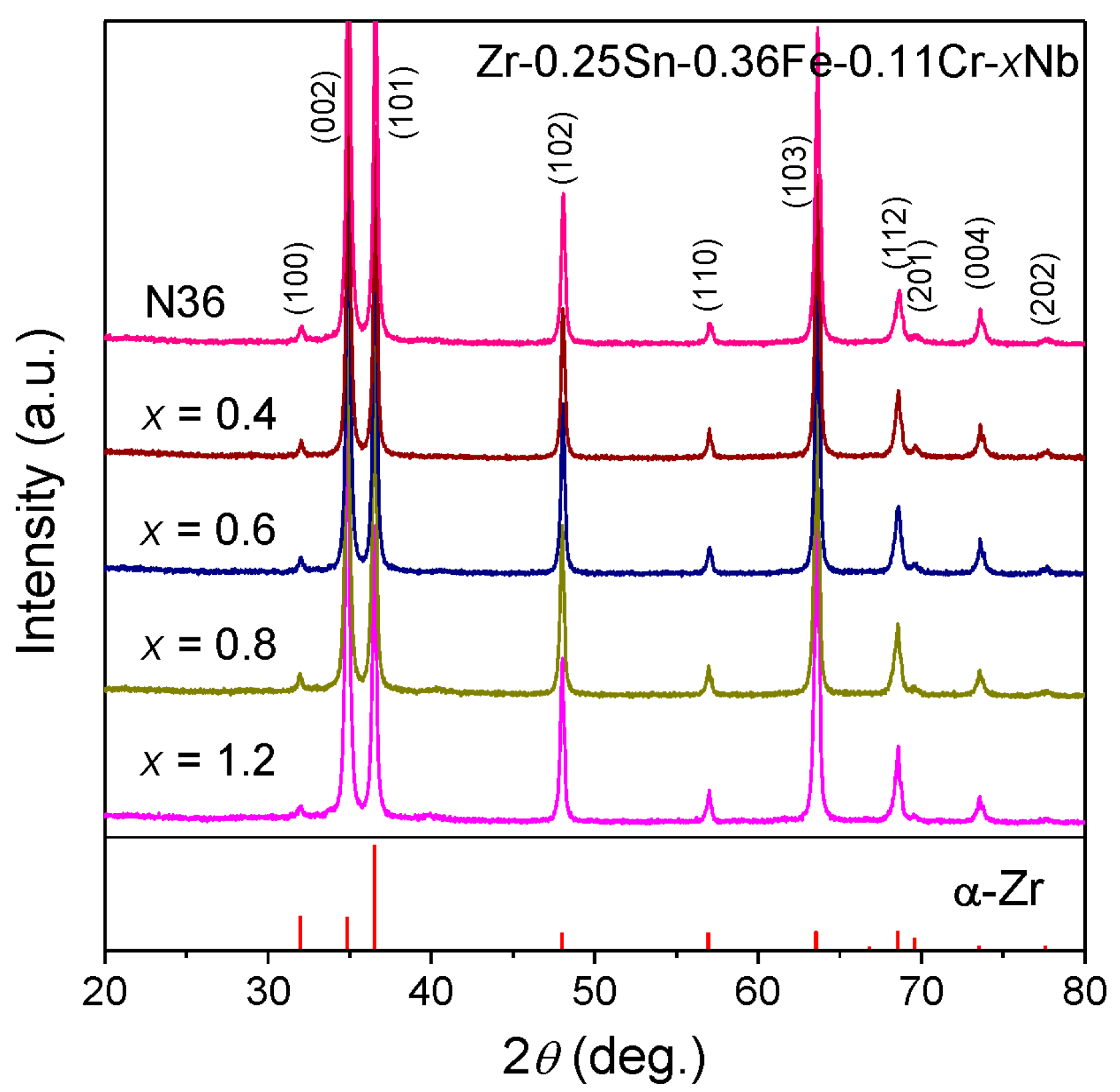
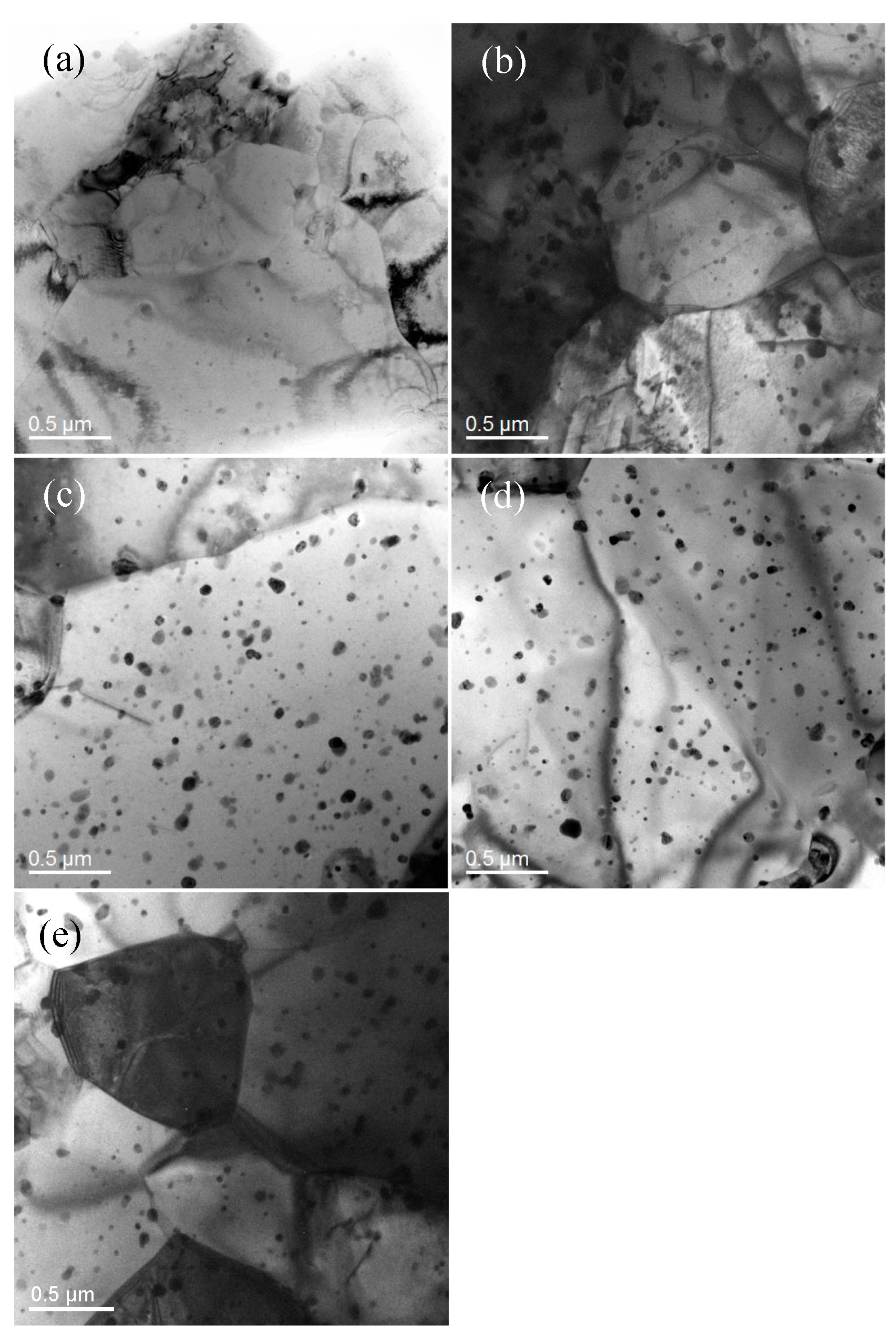
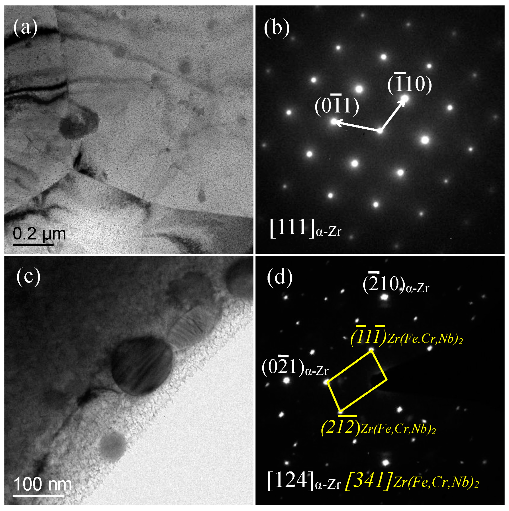
3.1. Microstructure Characterization

The XRD results (Figure 1) show that all the designed Zr-0.25Sn-0.36Fe-0.11Cr-xNb (Z-xNb) alloys, as well as the reference N36 alloy, exhibit a single hexagonal α-Zr structure. The lattice constants were calculated by single-peak fitting the (002), (101), and (102) peaks respectively with the Pearson VII function in Jade, and the average values with errors were listed in Table 1. For further identification of the second precipitated phases, the TEM observations were executed, as shown in Figure 2. It could be found that these precipitated particles are distributed uniformly on the α-Zr matrix, and the amount of precipitates increases with the Nb content from x = 0.4 to x = 1.2 (Figure 2a–d). The particle sizes in all these alloys are almost constant, being about 50–100 nm. In the Z-0.4Nb alloy (Figure 2a), the precipitates are scarce, indicating that the alloying elements are almost soluble in the α-Zr matrix. While in the other Zr-xNb alloys with x = 0.8~1.2, the amounts of the precipitates are relatively higher, more than that in the N36 alloy (Zr-1.0Sn-1.0Nb-0.25Fe) with a high Sn content (Figure 2b–e).
The selected-area electron diffraction (SAED) analysis of TEM indicates that on the α-Zr matrix, the second precipitates are identified as a Laves phase Zr(Fe,Cr,Nb)2 with a hexagonal structure. Specifically, Figure 3a gives the TEM results of the Z-0.4Nb alloy with a minor amount of second particles, showing the matrix with a hexagonal structure in [111]α direction (Figure 3b). The spherical particles in the Z-1.2Nb alloy also exhibit a hexagonal structure, identified as the Laves Zr(Fe,Cr,Nb)2 phase by the SAED pattern with the [341] direction (Figure 3c,d). The lattice constants of the precipitates in the Z-1.2Nb are a = 0.502 nm and c = 0.818 nm, respectively, close to those reported values of Laves phases of Zr(Fe,Cr,Nb)2 (a = 0.54 nm, c = 0.87 nm) in the Zr-1.6Sn-0.6Nb-0.2Fe-0.1Cr alloy [18].
According to the lattice constants of the α-Zr matrix in this Z-xNb alloy series listed in Table 1, it could be found that the lattice constants (a and c) increase gradually with the Nb content from x = 0.4 to x = 1.2. It results from the precipitation of the solutes in the form of intermetallic compound since the atomic radii of all the solutes are smaller than that of Zr, being RSn = 0.140 nm, RNb = 0.147 nm, RFe = 0.127 nm, RCr = 0.128 nm, and RZr = 0.160 nm [26], respectively. Among them, the atomic radii of Nb, Fe, Cr, and Zr are Goldschmidt radii, while that of Sn is a covalent radius due to the strong interaction between Sn and Zr (larger negative enthalpy of mixing ΔH = −43 kJ/mol [26]). It was also confirmed by the TEM results that the amount of the second particles in this alloy series increases with Nb (Figure 2a–d). However, the largest lattice constants (a = 0.3229 nm and c = 0.5146 nm) of the Z-0.8Nb and Z-1.2Nb alloys are slightly lower than that of pure Zr (a = 0.3232 nm and c = 0.5148 nm [27]), implying that a certain amount of solute elements (Sn and Nb) is still solid-solutioned into the matrix. In comparison, the lattice constants (a = 0.3226 nm and c = 0.5137 nm) of the reference N36 alloy with a high Sn is the smallest, smaller than that of the Z-0.4Nb alloy, which because a much higher content of Sn could be soluble in the matrix due to large solubility (about 1.2 wt %) of Sn in α-Zr [18,19,20].

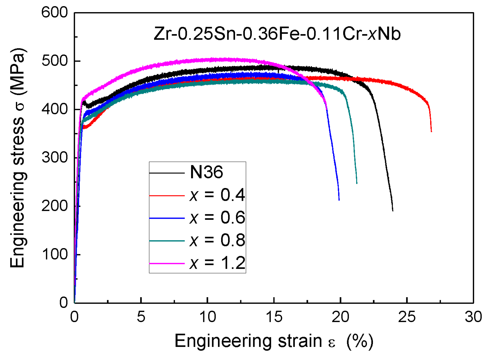
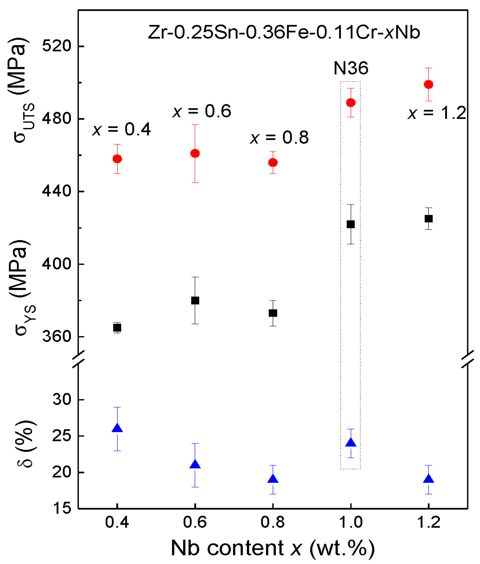
3.2. Mechanical Tensile Properties

The engineering tensile stress-strain curves of the designed Z-xNb alloys and the reference N36 alloy are shown in Figure 4, from which the mechanical property parameters, including the yield strength σYS, the ultimate tensile strength σUTS, and the elongation to fracture δ, could be obtained. All these values are listed in Table 1. Figure 5 gives the variation tendencies of σYS, σUTS, and δ of these alloys with the Nb content, in which the strengths of Zr alloys keep at a relatively lower level (σUTS ~ 460 MPa) when the Nb content is not more than 0.80 wt %. The Z-0.4Nb alloy with the lowest Nb content in this series has the best tensile ductility with δ = 26.5%. When Nb increases to x = 1.2 wt %, the alloy strength is enhanced obviously by precipitation strengthening, as demonstrated by the fact that the Z-1.2Nb alloy shows the highest strength with σYS = 425 MPa and σUTS = 499 MPa, comparable to that of the reference N36 alloy (σYS = 422 MPa and σUTS = 489 MPa) measured under the same condition. It indicates that the increase of Nb in low-Sn Zr alloys can also achieve a relatively higher strength. In addition, all of these alloys possess good ductility with the δ = 18~27%.

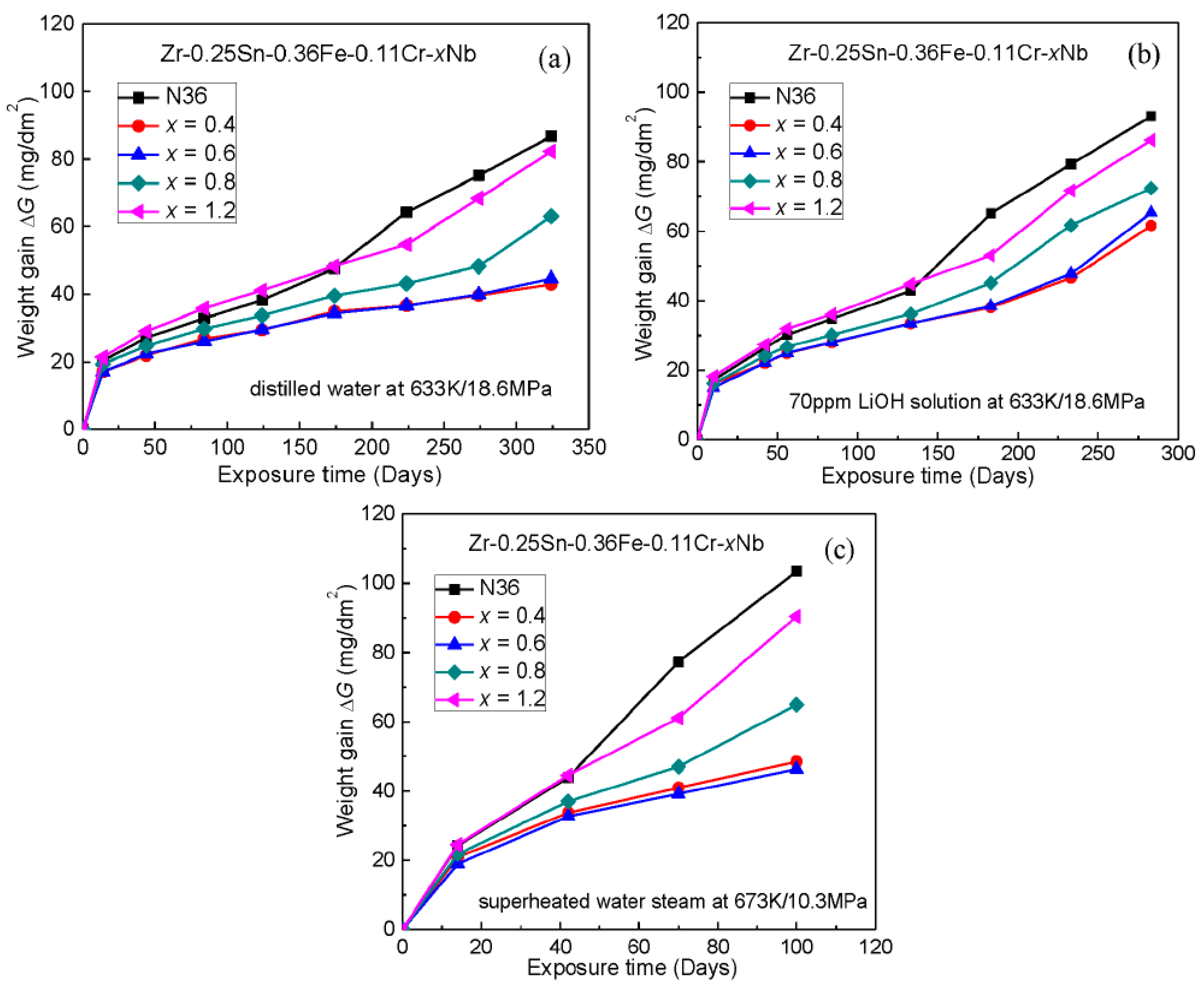
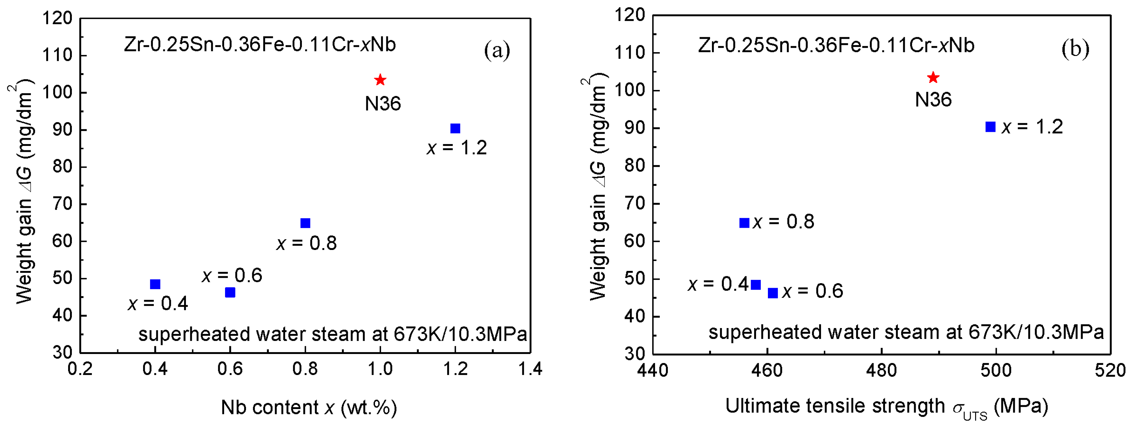
3.3. Autoclave Corrosion Resistances

In order to investigate the general autoclave corrosion behaviors of the designed low-Sn Z-xNb alloys, the corrosion weight gains of these alloys and N36 were measured in the distilled water at 633 K/18.6 MPa, as shown in Figure 6a. It can be seen that the corrosion behaviors of this low-Sn Zr alloy series change with increasing Nb content. For the reference N36 alloy with a high content of Sn, the corrosion weight gain ΔG increases slowly before the 150-day exposure and is then enhanced sharply, as evidenced by the ΔG = 86.8 mg/dm2 after exposure for 324 days. The corrosion gains of all the designed low-Sn Z-xNb alloys are lower than that of N36. Specially, the Z-xNb alloys with a low Nb content (x ≤ 0.6) exhibit the excellent corrosion resistance, in which the ΔGs are about 44 mg/dm2 after the 324-day exposure, only half of that of N36. With increasing the Nb content (0.8~1.2 wt %), the corrosion weight gains of alloys are increased, being 63 mg/dm2 (Z-0.8Nb) and 80 mg/dm2 (Z-1.2Nb), respectively.
The corrosion behaviors of this low-Sn Zr alloy series in the 70 ppm LiOH aqueous solution at 633 K/18.6 MPa (the simulated in-pile hydrochemical condition) follow a similar variation tendency with the Nb content to that in the distilled water, as shown in Figure 6b. The reference alloy N36 undergoes a corrosion transition at about 125 days of exposure, and then the corrosion gain increases significantly, with a ΔG of 93.1 mg/dm2 after tested for 283 days. The low-Sn and low-Nb alloys (Z-0.4Nb and Z-0.6Nb) still possess the excellent corrosion resistance with a ΔG of about 63.5 mg/dm2 for 283-day exposure, which is about 70% of the N36. The corrosion resistances of the high-Nb alloys (Z-0.8Nb and Z-1.2Nb) are inferior to those of the low-Nb alloys, but still better than that of N36, in which the corrosion weight gains are within the range of 72.4~86.2 mg/dm2 for the 283-day exposure.
In order to further study the uniform corrosion behavior of these designed alloys, the 100-day corrosion tests were carried out in superheated water steam at 673 K/10.3 MPa, and the corrosion weight gain curves are shown in Figure 6c. The corrosion rate of the reference N36 was accelerated after the 40-day exposure, and the ΔG reached 103.4 mg/dm2 for the 100-day exposure. In comparison, the corrosion resistances of the low-Sn Zr alloys are obviously better than that of the N36. Similarly, the low-Sn and low-Nb alloys (Z-0.4Nb and Z-0.6Nb) have excellent corrosion resistance with ΔGs of only about 47.0 mg/dm2 after the 100-day exposure, less than half of that of the N36. Increasing Nb would reduce the corrosion resistances, as demonstrated by the fact that the ΔG of the Z-1.2Nb alloy increases up to 90.4 mg/dm2.
Since the variation tendencies of corrosion weight gains ΔG of the designed low-Sn Z-xNb alloys in the present three corrosion environments with the Nb content are similar, the variation of the ΔG vs. the Nb content in the superheated water steam at 673 K/10.3 MPa for 100-day exposure is specially shown in Figure 7a. It could be found that the ΔG values of these designed alloys increase with the Nb, indicating that the corrosion resistance of these low-Sn alloys would be reduced with the amount of precipitates increasing. Among them, the corrosion gains ΔG of the Z-(0.4~0.6)Nb alloys are the minimum, about 47.0 mg/dm2 for 100-day exposure. Although the ΔG of the Z-1.2Nb alloy with a higher Nb is the maximum (ΔG = 103.4 mg/dm2) in this designed series, it exhibits a better corrosion resistance than the reference N36 alloy (ΔG = 103.4 mg/dm2).
Moreover, Table 1 also gives the atomic percent expression of the designed alloys and the reference N36. It is found that the Z-1.2Nb alloy contains the same content of solute elements (2.15 at %) as the N36, as a result that the tensile strengths of these two alloys are comparable strengthened by both solid solution and precipitation [28]. While the better corrosion resistance of the Z-1.2Nb alloy in above three autoclave corrosion environments is due to a much smaller amount of Sn (0.20 at %) soluble in the α-Zr matrix, in comparison to that of the N36 alloy containing a high soluble Sn content of 0.78 at % [18,19,20].
According to the strength and corrosion resistance of the designed low-Sn Z-xNb alloys, as shown in Figure 7b—being the relationship of the σUTS with the ΔG (in the superheated water steam at 673 K/10.3 MPa for 100-day exposure)—these alloys could be classified into two groups. One group (Nb ≤ 0.8 wt %) exhibits the excellent corrosion resistance with a strength level of σUTS = 460 MPa, and the other shows a higher strength (σUTS = 499 MPa) and better corrosion resistance than the reference high-Sn N36 alloy (Zr-1.0Sn-1.0Nb-0.25Fe, σUTS = 489 MPa). Furthermore, the corrosion resistances under various environments of these low-Sn alloys are all better than that of the N36.

4. Conclusions

A new low-Sn Zr cladding alloy series of Zr-0.25Sn-0.36Fe-0.11Cr-xNb with high strength and excellent corrosion resistance were developed by changing Nb content (x = 0.4, 0.6, 0.8, 1.2). The designed low-Sn alloys exhibit excellent corrosion resistances in three out-of-pile autoclave environments (distilled water at 633 K/18.6 MPa, 70 ppm LiOH solution at 633 K/18.6 MPa, and superheated water steam at 673 K/10.3 MPa), as exampled by the Zr-0.25Sn-0.36Fe-0.11Cr-0.6Nb alloy (wt %) with the corrosion weight gain ΔG = 46.3 mg/dm2 for 100-day exposure in the superheated water steam environment and with a tensile strength of σUTS = 460 MPa. A large amount of precipitates on the α-Zr matrix with an increase of Nb can enhance the strength of these low-Sn alloys up to σUTS = 499 MPa, comparable to that of the reference high-Sn N36 alloy (Zr-1.0Sn-1.0Nb-0.25Fe wt %, σUTS = 489 MPa). More importantly, all the corrosion resistance of these high-strength and low-Sn alloys (e.g., Zr-0.25Sn-0.36Fe-0.06Cr-1.2Nb with ΔG = 90.4 mg/dm2 for 100-day exposure in the water steam at 674 K/10.3 MPa) is still better than that of N36 (ΔG = 103.4 mg/dm2 under the same condition).

Acknowledgments

This work was supported by the International Thermonuclear Experimental Reactor (ITER) Program of China [No. 2015GB121004], the International Science & Technology Cooperation Program of China [No. 2015DFR60370], the Natural Science Foundation of Liaoning Province of China [No. 2015020202], and the Fundamental Research Funds for the Central Universities [No. DUT16ZD212].

Author Contributions

Ruiqian Zhang and Qing Wang conceived and designed the experiments and wrote the paper; Chang Pang and Beibei Jiang performed the experiments and analyzed the data; Xun Dai, Yongduo Sun, and Wei Liao provided assistance in the experiments and contributed reagents/materials; Chuang Dong modified the paper.

Conflicts of Interest

The authors declare no conflicts of interest.

References

  1. Park, J.-Y.; Yoo, S.J.; Choi, B.-K.; Jeong, Y.H. Corrosion and oxide characteristics of Zr-1.5Nb-0.4Sn-0.2Fe-0.1Cr alloys in 360 °C pure water and LiOH solution. J. Nucl. Mater. 2008, 373, 343–350. [Google Scholar] [CrossRef]
  2. Yao, M.Y.; Zhou, B.X.; Li, Q.; Liu, W.Q.; Geng, X.; Lu, Y.P. A superior corrosion behavior of Zircaloy-4 in lithiated water at 360 °C/18.6 MPa by β-quenching. J. Nucl. Mater. 2008, 374, 197–203. [Google Scholar] [CrossRef]
  3. Thorvaldsson, T.; Andersson, T.; Wilson, A.; Wardle, A. Correlation between 400 °C steam corrosion behavior, heat treatment, and microstructure of Zircaloy-4 tubing. In Zirconium in the Nuclear Industry: Eighth International Symposium; Van Swam, L.F.P., Eucken, C.M., Eds.; ASTM International: Baltimore, MD, USA, 1989; pp. 128–140. [Google Scholar]
  4. Kim, H.G.; Jeong, Y.H.; Kim, T.H. Effect of isothermal annealing on the corrosion behavior of Zr-xNb alloys. J. Nucl. Mater. 2004, 326, 125–131. [Google Scholar] [CrossRef]
  5. Zhao, W.; Liu, Y.; Jiang, H.; Peng, Q. Effect of heat treatment and Nb and H contents on the phase transformation of N18 and N36 zirconium alloys. J. Alloys Compd. 2008, 462, 103–108. [Google Scholar] [CrossRef]
  6. Sabol, G.P. ZIRLOTM—An Alloy Development Success. In Zirconium in the Nuclear Industry: 14th International Symposium; Ruding, P., Kammenzind, B., Eds.; ASTM International: Bridgeport, CT, USA, 2005; Volume 2, pp. 3–24. [Google Scholar]
  7. Bossis, P.; Pecheur, D.; Hanifi, K.; Thomazet, J.; Blat, M. Comparison of the high burn-up corrosion on M5 and low tin Zircaloy-4. In Zirconium in the Nuclear Industry: 14th International Symposium; Ruding, P., Kammenzind, B., Eds.; ASTM International: Bridgeport, CT, USA, 2005; Volume 3, pp. 494–525. [Google Scholar]
  8. Shishov, V.; Peregud, M.; Nikulina, A.; Kon’kov, V.; Novikov, V.; Markelov, V.; Khokhunova, T.; Kobylyansky, G.; Novoselov, A.; Ostrovsky, Z. Structure-phase state, corrosion and irradiation properties of Zr-Nb-Fe-Sn system alloys. In Zirconium in the Nuclear Industry: 15th International Symposium; Kammenzind, B., Limbäck, M., Eds.; ASTM International: Baltimore, MD, USA, 2009; Volume 5, pp. 724–743. [Google Scholar]
  9. Yamate, K.; Oe, A.; Hayashi, M.; Okamoto, T.; Anada, H.; Hagi, S. Burnup extension of Japanese PWR fuels. In Proceedings of the 1997 International Topical Meeting on LWR Fuel Performance Conference, Portland, OR, USA, 2–6 March 1997; pp. 318–325. [Google Scholar]
  10. Zhou, B.X.; Yao, M.Y.; Li, Z.K.; Wang, X.M.; Zhou, J.; Long, C.S.; Liu, Q.; Luan, B.F. Optimization of N18 zirconium alloy for fuel cladding of water reactors. J. Mater. Sci. Technol. 2012, 28, 606–613. [Google Scholar] [CrossRef]
  11. Wei, J.; Frankel, P.; Polatidis, E.; Blat, M.; Ambard, A.; Comstock, R.; Hallstadius, L.; Hudson, D.; Smith, G.; Grovenor, C. The effect of Sn on autoclave corrosion performance and corrosion mechanisms in Zr-Sn-Nb alloys. Acta Mater. 2013, 61, 4200–4214. [Google Scholar] [CrossRef]
  12. Chun, Y.B.; Hwang, S.K.; Kim, M.H.; Kwun, S.I.; Kim, Y.S. Effect of Mo on recrystallization characteristics of Zr-Nb-(Sn)-Mo experimental alloys. J. Nucl. Mater. 1999, 265, 28–37. [Google Scholar] [CrossRef]
  13. Shishov, V.N.; Peregud, M.M.; Nikulina, A.V.; Pimenov, Y.V.; Kobylyansky, G.P.; Novoselov, A.E.; Ostrovsky, Z.E.; Obukhov, A.V. Influence of Structure—Phase State of Nb Containing Zr Alloys on Irradiation-Induced Growth. In Zirconium in the Nuclear Industry: 14th International Symposium; Ruding, P., Kammenzind, B., Eds.; ASTM International: Bridgeport, CT, USA, 2005; Volume 2, pp. 1–18. [Google Scholar]
  14. Kim, Y.-S.; Kim, S.-K.; Bang, J.-G.; Jung, Y.-H. Effects of Sn and Nb on massive hydriding kinetics of Zr-XSn-YNb alloy. J. Nucl. Mater. 2000, 279, 335–343. [Google Scholar] [CrossRef]
  15. Wadekar, S.; Raman, V.; Banerjee, S.; Asundi, M. Structure-property correlation of Zr-base alloys. J. Nucl. Mater. 1988, 151, 162–171. [Google Scholar] [CrossRef]
  16. Pêcheur, D. Oxidation of β-Nb and Zr(Fe,V)2 precipitates in oxide films formed on advanced Zr-based alloys. J. Nucl. Mater. 2000, 278, 195–201. [Google Scholar] [CrossRef]
  17. Steinbrück, M.; Böttcher, M. Air oxidation of Zircaloy-4, M5® and ZIRLO™ cladding alloys at high temperatures. J. Nucl. Mater. 2011, 414, 276–285. [Google Scholar] [CrossRef]
  18. Shen, H.; Peng, S.; Xiang, X.; Naab, F.; Sun, K.; Zu, X. Proton irradiation effects on the precipitate in a Zr-1.6Sn-0.6Nb-0.2Fe-0.1Cr alloy. J. Nucl. Mater. 2014, 452, 335–342. [Google Scholar] [CrossRef]
  19. Liu, W.; Li, Q.; Zhou, B.; Yan, Q.; Yao, M. Effect of heat treatment on the microstructure and corrosion resistance of a Zr-Sn-Nb-Fe-Cr alloy. J. Nucl. Mater. 2005, 341, 97–102. [Google Scholar] [CrossRef]
  20. Hong, H.S.; Moon, J.S.; Kim, S.J.; Lee, K.S. Investigation on the oxidation characteristics of copper-added modified Zircaloy-4 alloys in pressurized water at 360 °C. J. Nucl. Mater. 2001, 297, 113–119. [Google Scholar] [CrossRef]
  21. Lelievre, G.; Tessier, C.; Iltis, X.; Berthier, B.; Lefebvre, F. Impact of intermetallic precipitates on hydrogen distribution in the oxide layers formed on zirconium alloys in a steam atmosphere: A 2D (3He, p)α nuclear analysis study in microbeam mode. J. Alloys Compd. 1998, 268, 308–317. [Google Scholar] [CrossRef]
  22. Toffolon-Masclet, C.; Brachet, J.-C.; Jago, G. Studies of second phase particles in different zirconium alloys using extractive carbon replica and an electrolytic anodic dissolution procedure. J. Nucl. Mater. 2002, 305, 224–231. [Google Scholar] [CrossRef]
  23. Jeong, Y.H.; Kim, H.G.; Kim, T.H. Effect of β phase, precipitate and Nb-concentration in matrix on corrosion and oxide characteristics of Zr-xNb alloys. J. Nucl. Mater. 2003, 317, 1–12. [Google Scholar] [CrossRef]
  24. Shishov, V.N. The evolution of microstructure and deformation stability in Zr-Nb-(Sn, Fe) alloys under neutron irradiation. In Zirconium in the Nuclear Industry: 16th International Symposium; Limbäck, M., Barbéris, P., Eds.; ASTM International: Baltimore, MD, USA, 2012; Volume 7, pp. 200–213. [Google Scholar]
  25. Waseda, Y.; Matsubara, E.; Shinoda, K. X-ray Diffraction Crystallography; Springer: Heidelberg, Germany, 2011; pp. 107–127. [Google Scholar]
  26. Takeuchi, A.; Inoue, A. Classification of bulk metallic glasses by atomic size difference, heat of mixing and period of constituent elements and its application to characterization of the main alloying element. Mater. Trans. 2005, 46, 2817–2829. [Google Scholar] [CrossRef]
  27. Russell, R.B. Coefficients of thermal expansion for zirconium. J. Metals 1954, 6, 1045–1052. [Google Scholar]
  28. Curtis, R.E.; Dressier, G. Effect of thermomechanical processing and heat treatment on the properties of Zr-3Nb-lSn strip and tubing. In Zirconium in the Nuclear Applications; Schemel, J.H., Rosenbaum, H.S., Eds.; ASTM International: Harrisburg, PA, USA, 1974; Volume 551, pp. 104–128. [Google Scholar]
Figure 1. XRD patterns of the designed low-Sn Zr-0.25Sn-0.36Fe-0.11Cr-xNb (Z-xNb) alloys and the reference N36.
Metals 07 00144 g001
Figure 2. TEM bright field images of the designed Zr-0.25Sn-0.36Fe-0.11Cr-xNb alloys, (a) x = 0.4; (b) x = 0.6; (c) x = 0.8; (d) x = 1.2; and (e) N36.
Metals 07 00144 g002
Figure 3. TEM bright field images and SAED patterns of typical serial alloys. (a,b) Zr-0.25Sn-0.36Fe-0.11Cr-0.4Nb; and (c,d) Zr-0.25Sn-0.36Fe-0.11Cr-1.2Nb.
Metals 07 00144 g003
Figure 4. Engineering tensile stress-strain curves of the designed serial Zr-0.25Sn-0.36Fe-0.11Cr-xNb alloys.
Metals 07 00144 g004
Figure 5. Variations of mechanical properties vs. the Nb content in the designed low-Sn Zr-0.25Sn-0.36Fe-0.11Cr-xNb alloy series.
Metals 07 00144 g005
Figure 6. Corrosion behavior of the designed low-Sn Zr-0.25Sn-0.36Fe-0.11Cr-xNb alloys in different out of pile autoclave environments. (a) distilled water at 633 K/18.6 MPa; (b) 70 ppm LiOH solution at 633 K/18.6 MPa; and (c) superheated water steam at 673 K/10.3 MPa.
Metals 07 00144 g006
Figure 7. Variation of the corrosion weight gain ΔG in the superheated water steam at 673 K/10.3 MPa for 100-day exposure vs. the Nb content (a) and ultimate tensile strength σUTS; (b) of the designed low-Sn Zr-0.25Sn-0.36Fe-0.11Cr-xNb alloys.
Metals 07 00144 g007
Table 1. Compositions of the designed low-Sn Z-xNb alloy series and the lattice constants of the hexagonal HCP α-Zr matrix, as well as their mechanical tensile properties (σYS: yield strength, σUTS: ultimate tensile strength, δ: elongation to fracture).
CompositionsLattice ConstantsσYS (MPa)σUTS (MPa)δ (%)
(wt %)(at %)a (nm)c (nm)
Zr-0.25Sn-0.36Fe-0.11Cr-0.40Nb (Z-0.4Nb)Zr98.63Sn0.20Nb0.39Fe0.59Cr0.200.3228 ± 0.00010.5137 ± 0.000136545826.5
Zr-0.25Sn-0.36Fe-0.11Cr-0.60Nb (Z-0.6Nb)Zr98.44Sn0.20Nb0.59Fe0.59Cr0.200.3229 ± 0.00030.5137 ± 0.000138046118.6
Zr-0.25Sn-0.36Fe-0.11Cr-0.80Nb (Z-0.8Nb)Zr98.24Sn0.20Nb0.78Fe0.59Cr0.200.3229 ± 0.00020.5146 ± 0.000137345620.2
Zr-0.25Sn-0.36Fe-0.11Cr-1.20Nb (Z-1.2Nb)Zr97.85Sn0.20Nb1.17Fe0.59Cr0.200.3229 ± 0.00030.5146 ± 0.000142549918.4
Zr-1.0Sn-0.25Fe-1.0Nb (N36 (Ref.))Zr97.85Sn0.78Nb0.98Fe0.390.3226 ± 0.00030.5137 ± 0.000142248922.3

