Influence of Process Parameters on the Vertical Forces Generated during Friction Stir Welding of AA6082-T6 and on the Mechanical Properties of the Joints


Abstract
:
1. Introduction
2. Experimental Procedures
3. Results and Discussion
4. Conclusions
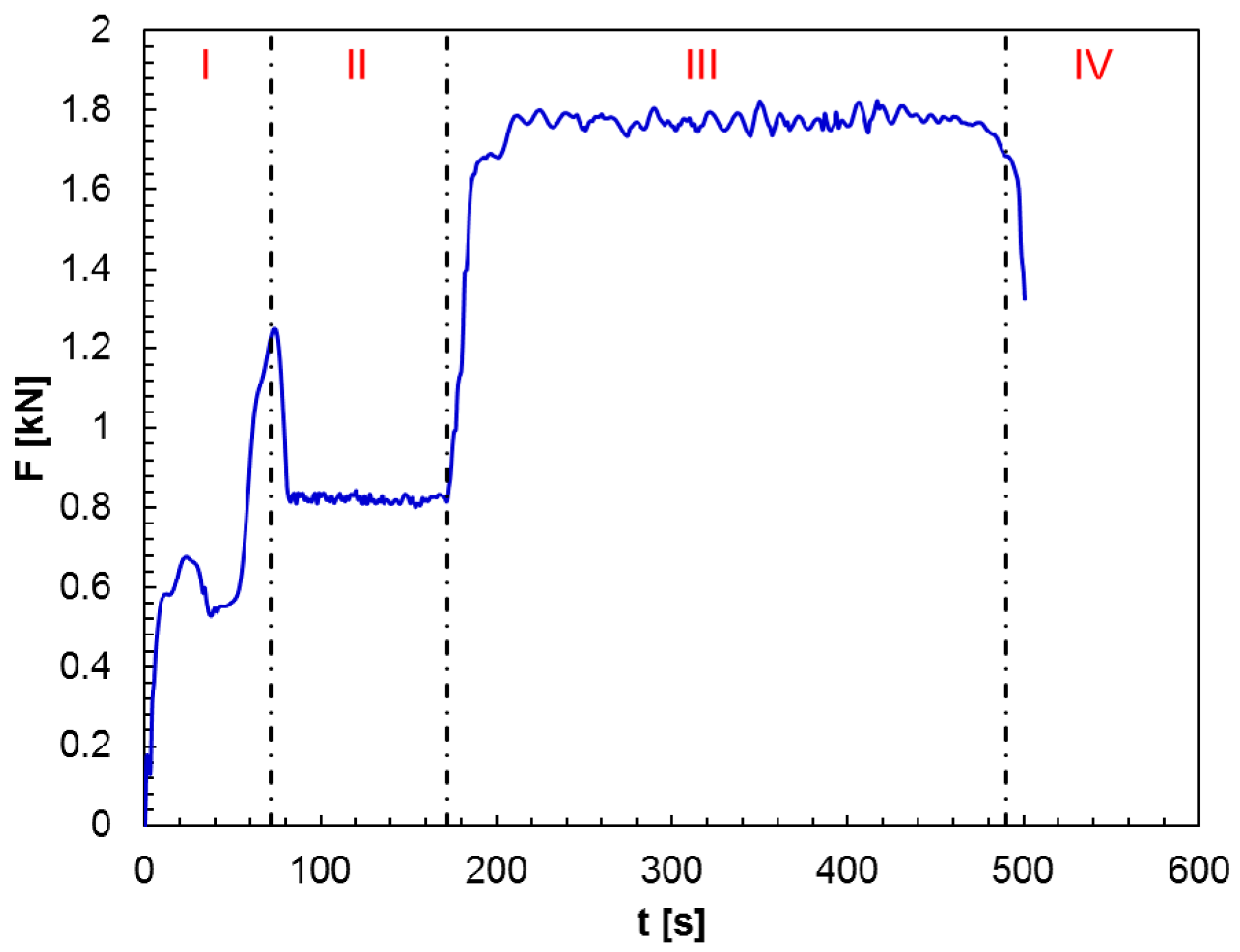
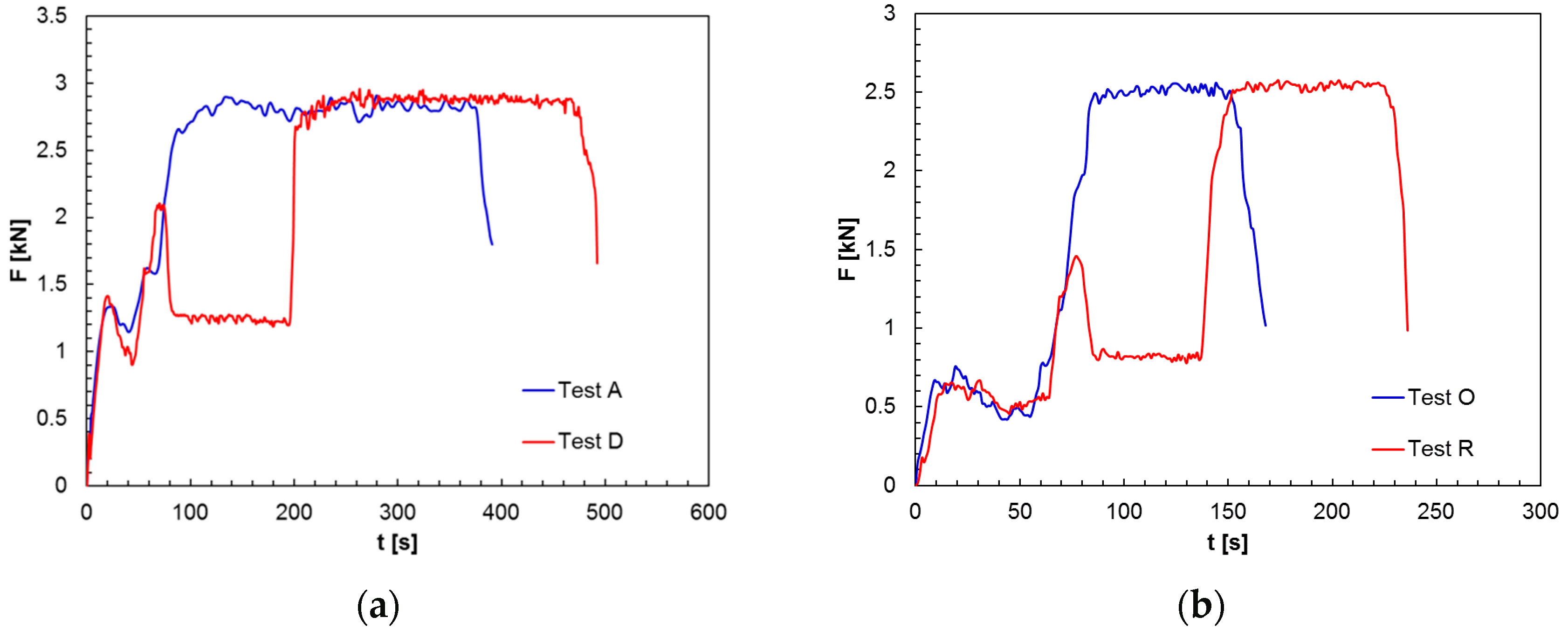
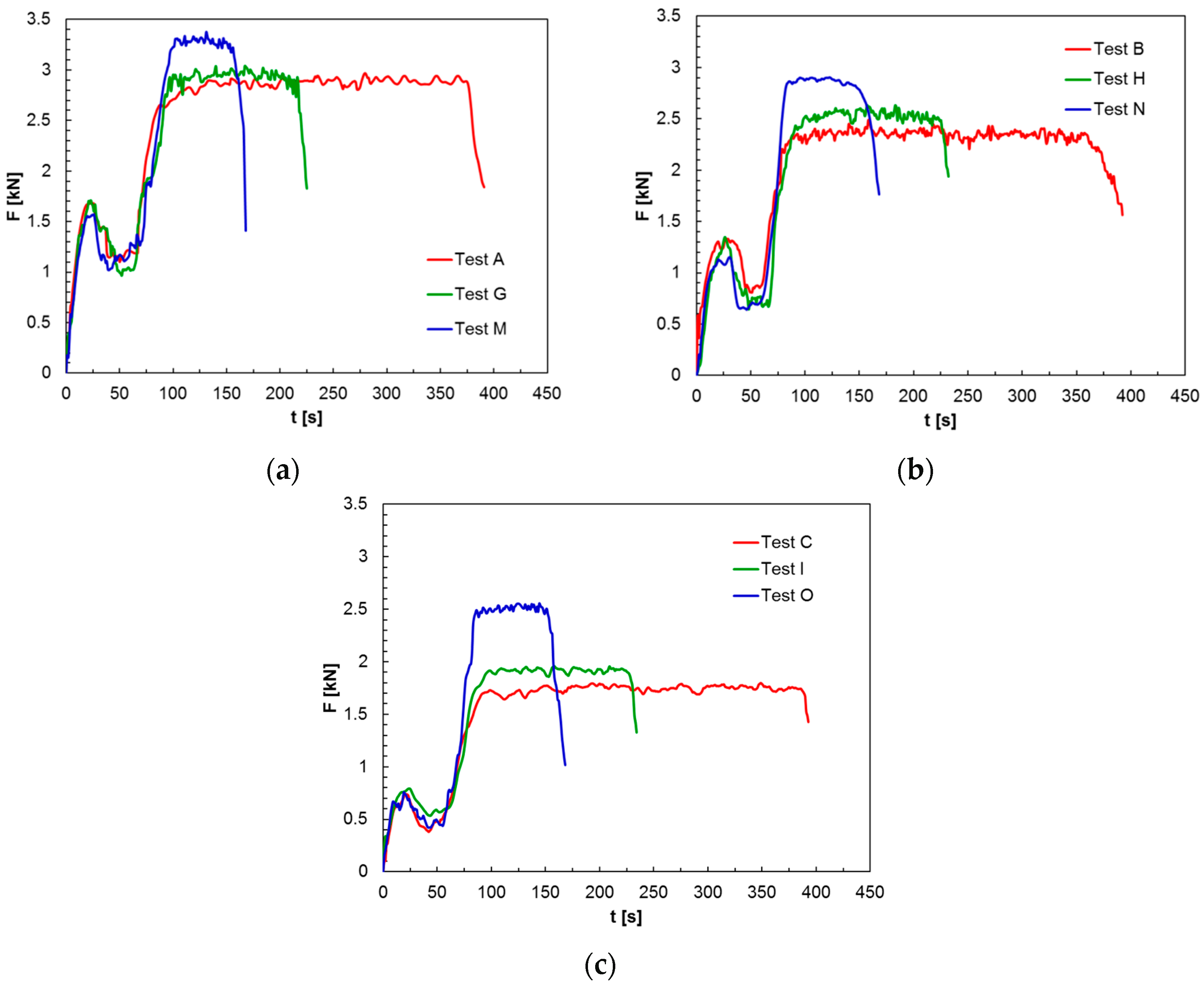
- plunging, dwelling, welding, and pulling out stages characterise the F-t curves;
- the vertical force increases, decreases, and backs to increase with rising processing time throughout the tool plunging. Such very complex behaviour can be attributed to the occurrence of both primary and secondary plunging;
- in spite of softening caused by the rotating tool action, the dwelling stage does not significantly affect the vertical force in the subsequent stage;
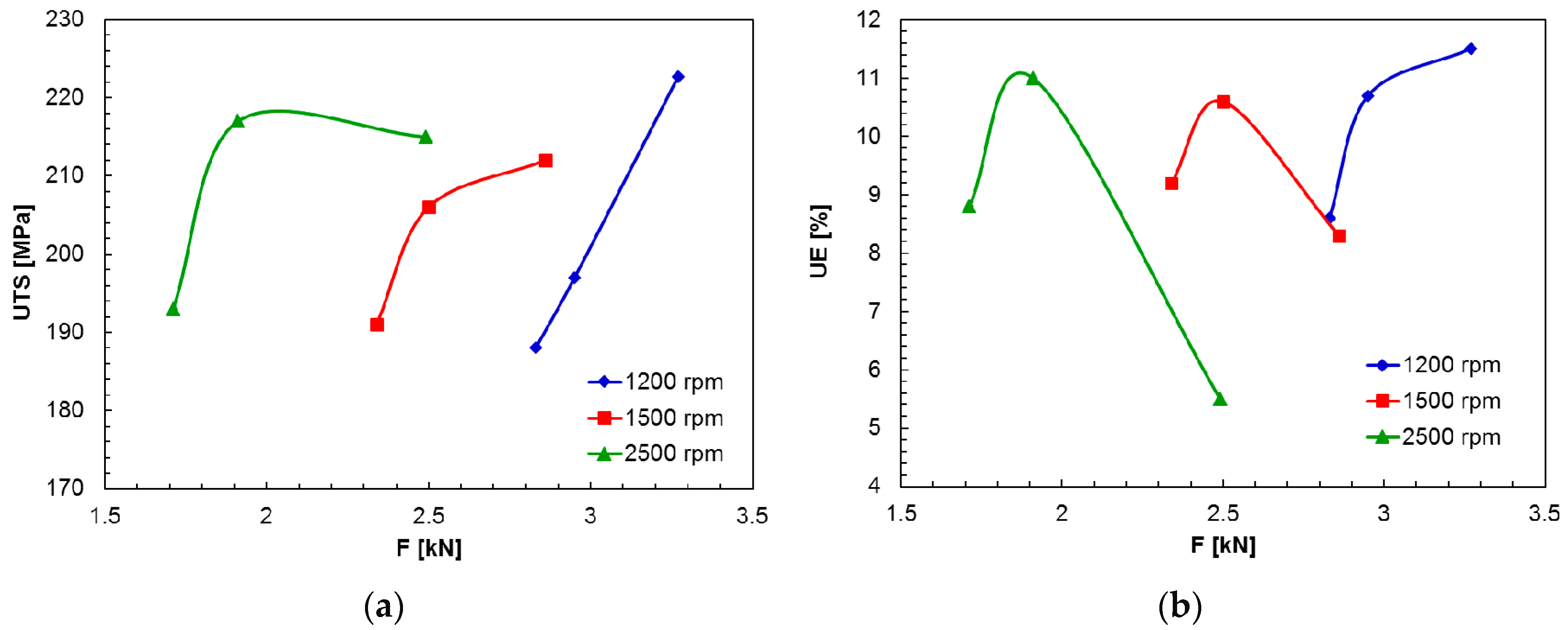
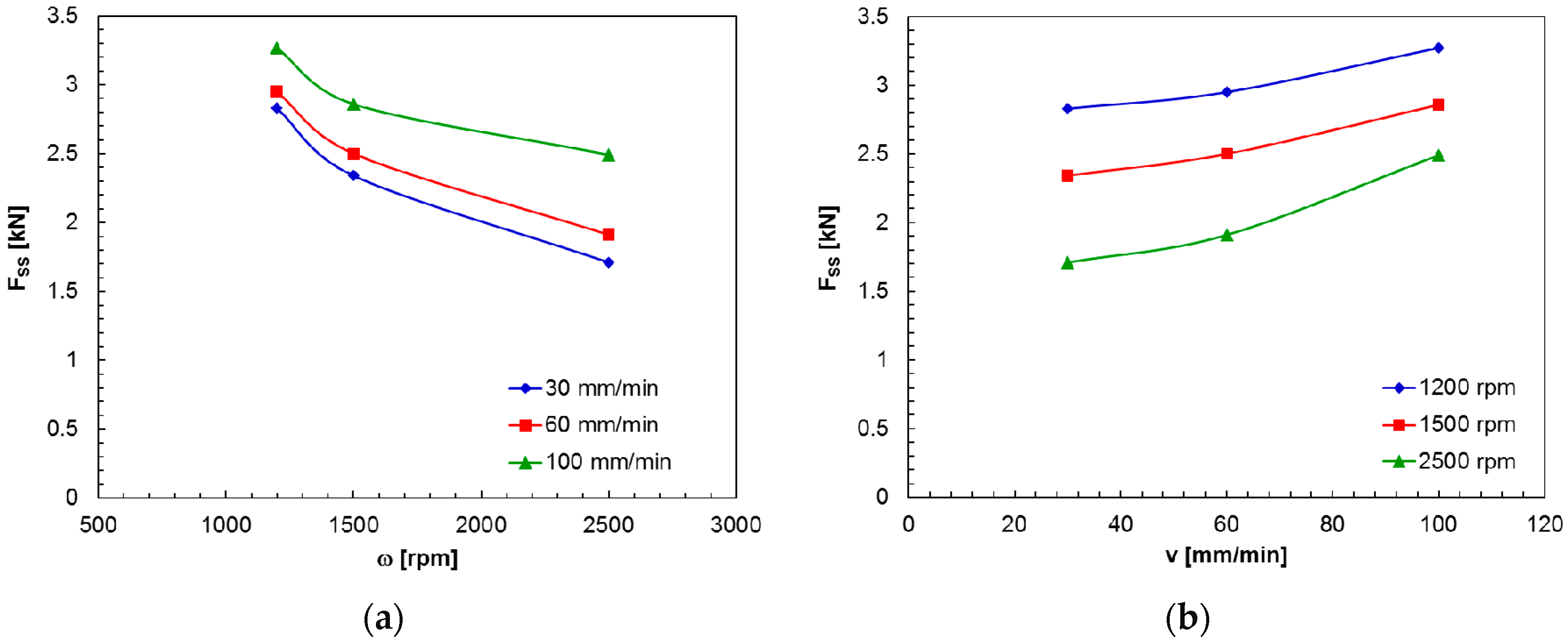
- the F value grows and immediately gains a constant value as the tool began its welding motion. Moreover, the vertical force increases with growing welding speed and diminishing rotational speed;
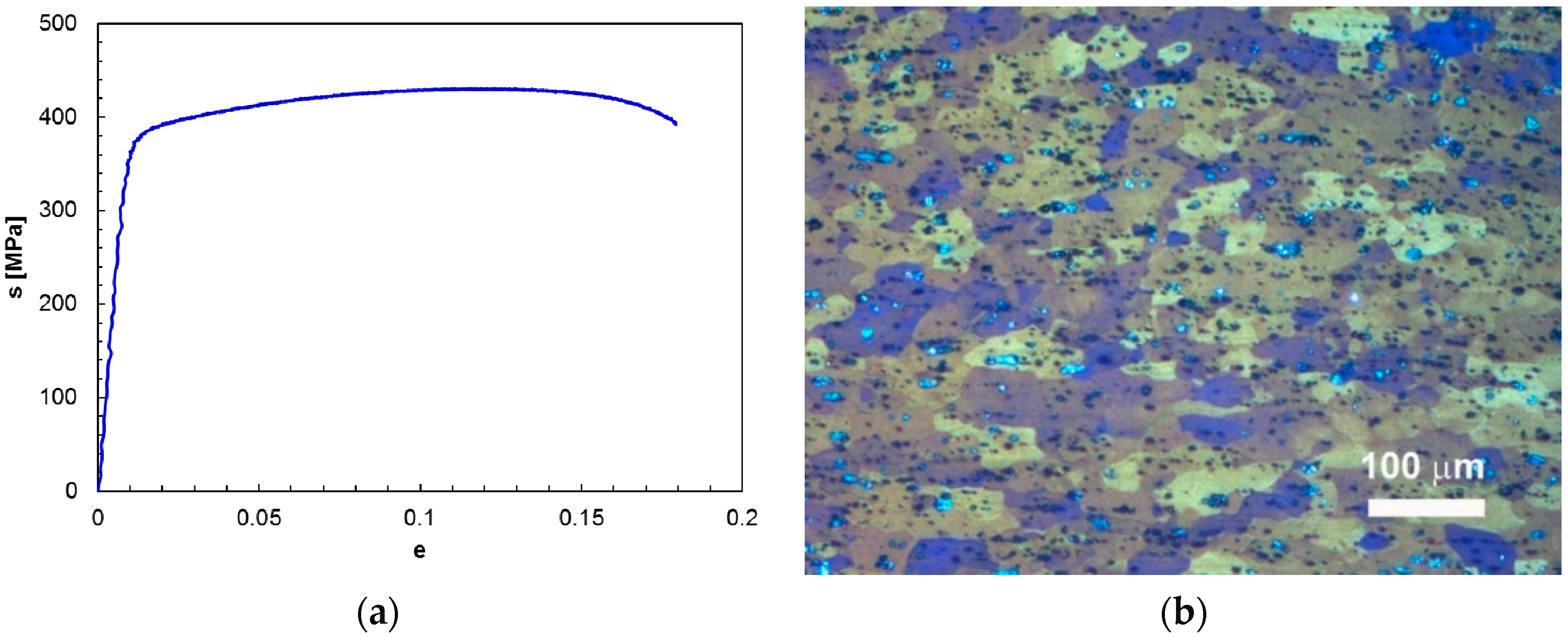
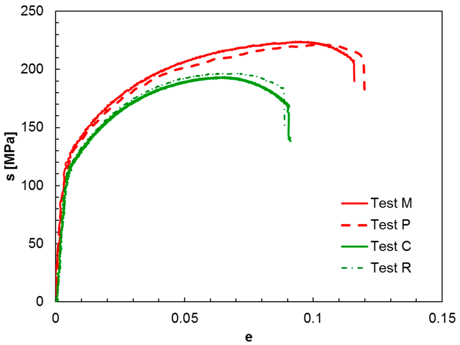
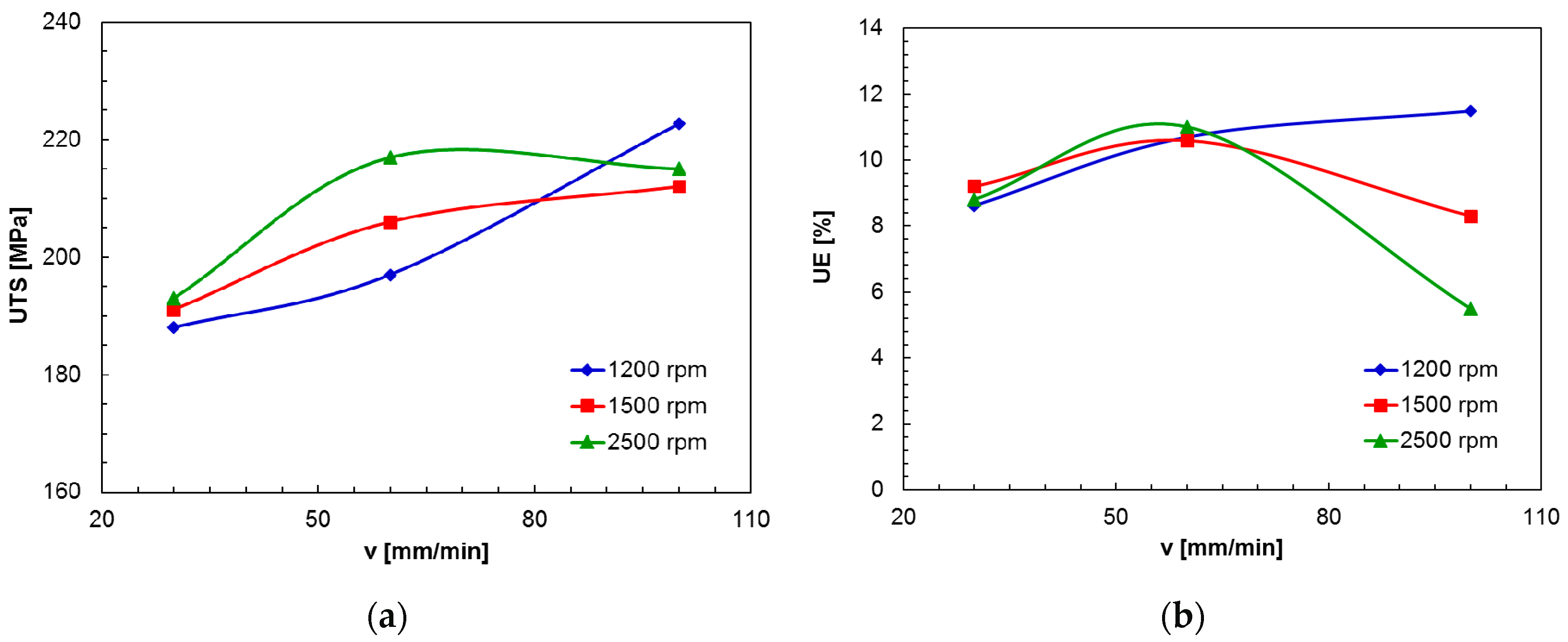
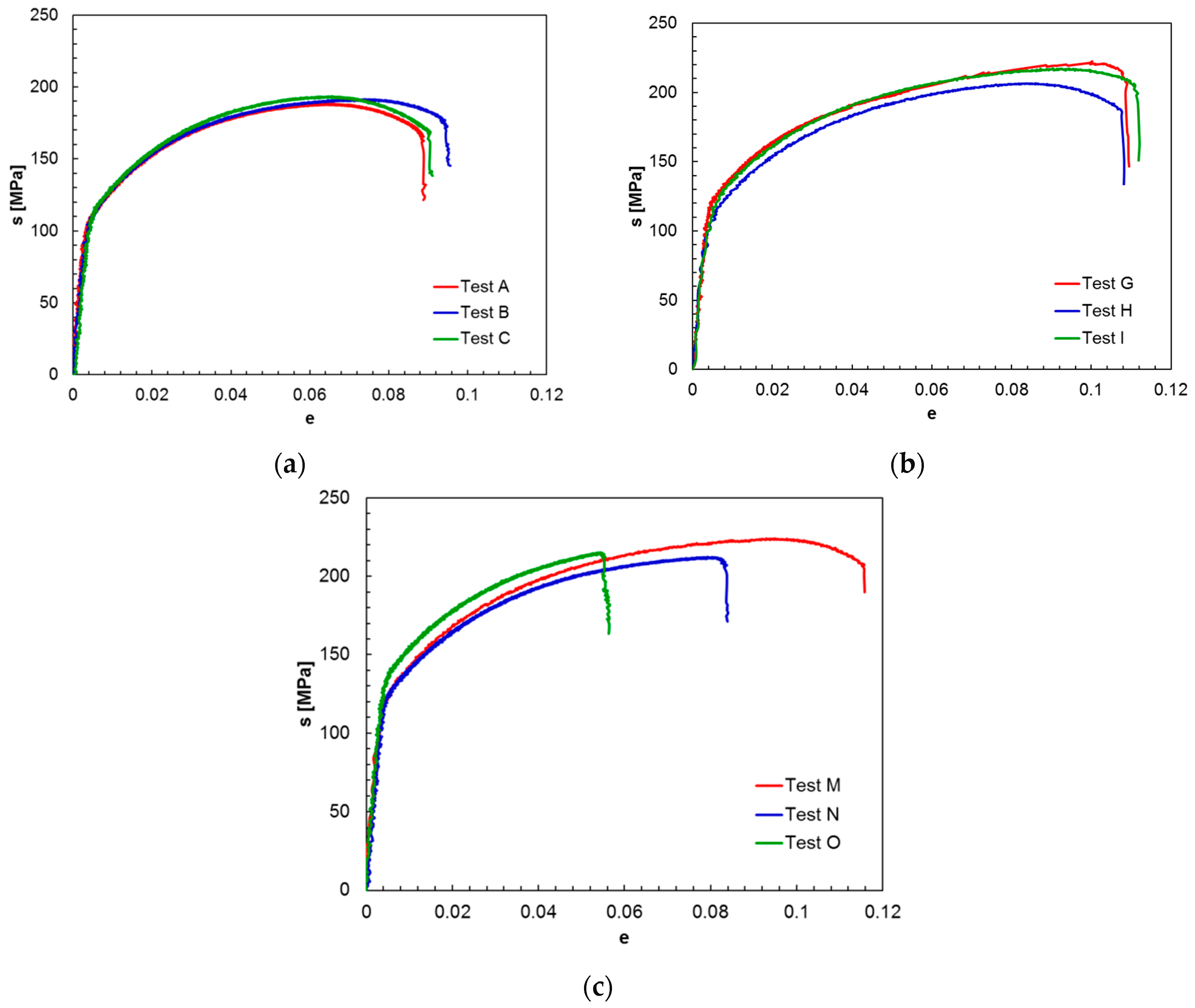
- both ultimate tensile strength and ultimate elongation of the welds grow with welding speed up to 60 mm/min. For v = 100 mm/min, the mechanical properties strongly depend on the tool rotational speed;
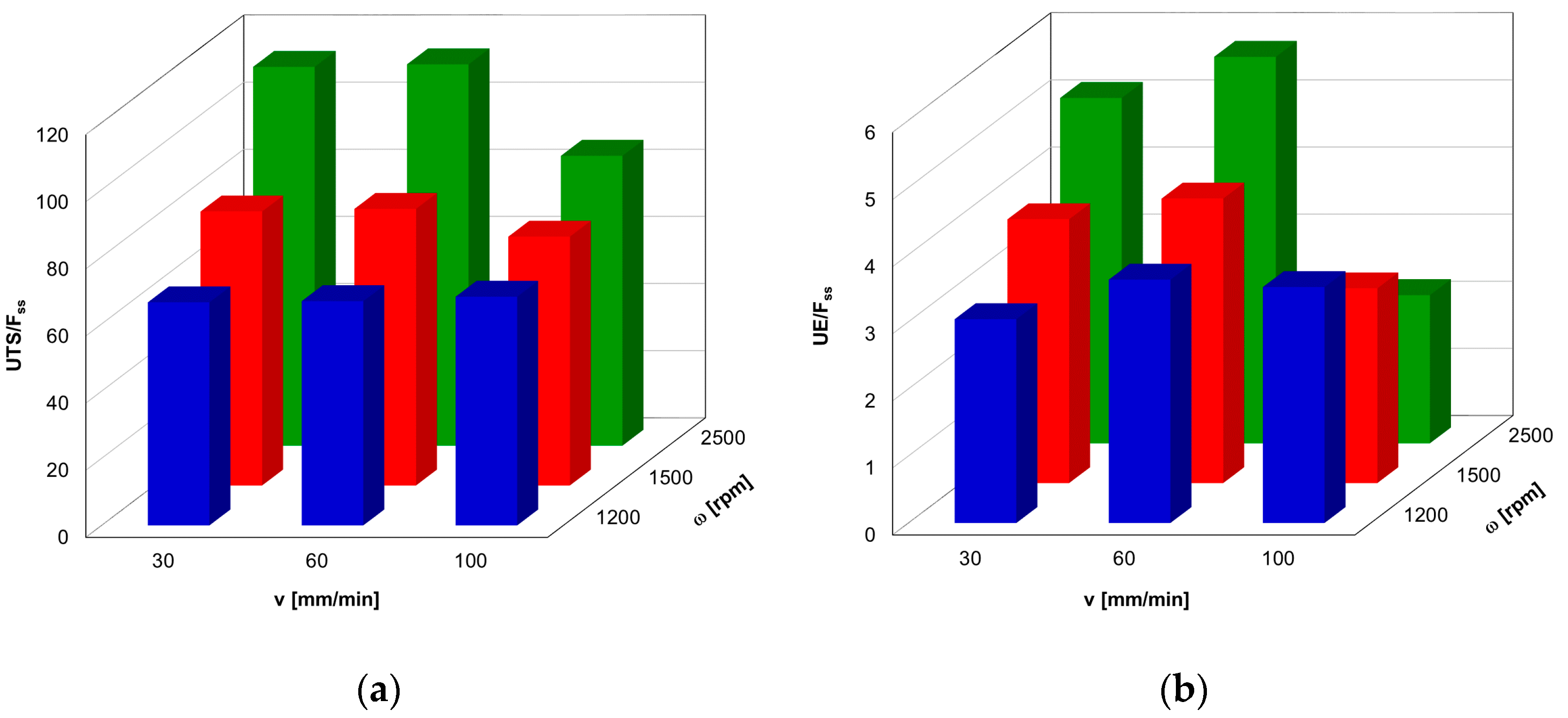
- the best compromise among the need to maximize the mechanical properties and the requirement to minimize the vertical force is obtained performing FSW at ω = 2500 rpm and v = 60 mm/min;
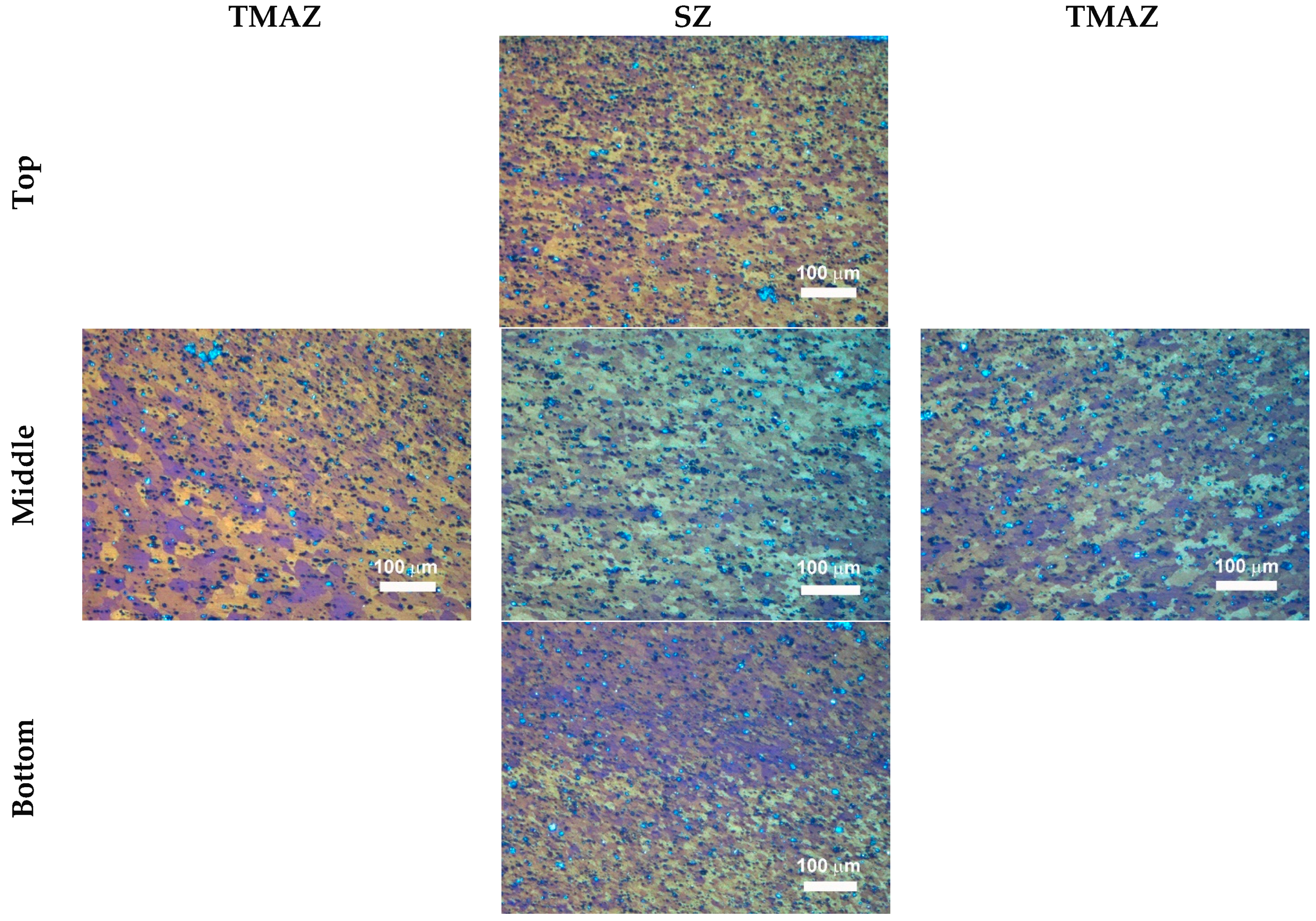
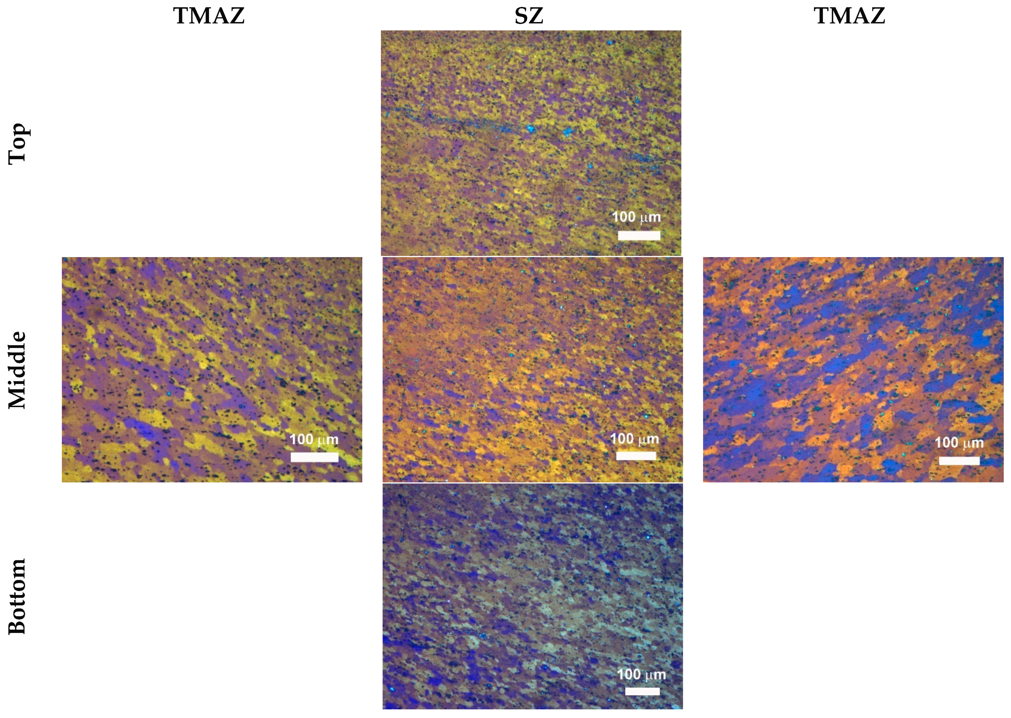
- a direct correlation between ultimate tensile strength and vertical force and between ultimate elongation and vertical force is achieved as ω = 1200 rpm. More complex relationships among the mechanical properties and vertical force are obtained as higher rotational speeds are concerned owing to the heterogeneity of both second phase particles and grain size which are more marked as the FSW is carried out at the highest welding and rotational speeds.
Acknowledgments
Author Contributions
Conflicts of Interest
References
- Mishra, R.S.; Ma, Z.Y. Friction stir welding and processing. Mater. Sci. Eng. Rep. 2005, 50, 1–78. [Google Scholar] [CrossRef]
- Nandan, R.; DebRoy, T.; Bhadeshia, H.K.D.H. Recent advances in friction stir welding process, weldment structure and properties. Prog. Mater. Sci. 2008, 53, 980–1023. [Google Scholar] [CrossRef]
- Kinsey, B.; Viswanathan, V.; Cao, J. Forming of aluminum tailor welded blanks. SAE Tech. Pap. 2001, 673–679. [Google Scholar] [CrossRef]
- Casalino, G.; Campanelli, S.; Mortello, M. Influence of shoulder geometry and coating of the tool on the friction stir welding of aluminium alloy plates. Procedia Eng. 2014, 69, 1541–1548. [Google Scholar] [CrossRef]
- Forcellese, A.; Simoncini, M. Plastic flow behaviour and formability of friction stir welded joints in AZ31 thin sheets obtained using the “pinless” tool configuration. Mater. Des. 2012, 36, 123–129. [Google Scholar] [CrossRef]
- Bruni, C.; Forcellese, A.; Gabrielli, F.; Simoncini, M. Post welding formability of AZ31 magnesium alloy. Mater. Des. 2011, 32, 2988–2991. [Google Scholar] [CrossRef]
- Fadaeifard, F.; Amin Matori, K.; Abd Aziz, S.; Zolkarnain, L.; Rahim, M.A.Z.B.A. Effect of the welding speed on the macrostructure, microstructure and mechanical properties of AA6061-T6 friction stir butt welds. Metals 2017, 7, 48. [Google Scholar] [CrossRef]
- Celik, S.; Cakir, R. Effect of friction stir welding parameters on the mechanical and microstructure properties of the Al-Cu butt joint. Metals 2016, 6, 133. [Google Scholar] [CrossRef]
- Sakthivel, T.; Sengar, G.S.; Mukhopadhyay, J. Effect of welding speed on microstructure and mechanical properties of friction-stir welded aluminum. Int. J. Adv. Manuf. Technol. 2009, 43, 468–473. [Google Scholar] [CrossRef]
- Sun, Y.; Tsuji, N.; Fujii, H. Microstructure and mechanical properties of dissimilar friction stir welding between ultrafine grained 1050 and 6061-T6 Aluminum alloys. Metals 2016, 6, 24. [Google Scholar] [CrossRef]
- Zimmer, S.; Langlois, L.; Laye, J.; Goussain, J.-C.; Martin, P.; Bigot, R. Influence of processing parameters on the tool and workpiece mechanical interaction during friction stir welding. Int. J. Mater. Form. 2009, 2, 299–302. [Google Scholar] [CrossRef] [Green Version]
- Yaduwanshi, D.K.; Bag, S.; Pal, S. Numerical modeling and experimental investigation on plasma-assisted hybrid friction stir welding of dissimilar materials. Mater. Des. 2016, 92, 166–183. [Google Scholar] [CrossRef]
- Ji, S.; Meng, X.; Liu, Z.; Huang, R.; Li, Z. Dissimilar friction stir welding of 6061 aluminum alloy and AZ31 magnesium alloy assisted with ultrasonic. Mater. Lett. 2017, 201, 173–176. [Google Scholar] [CrossRef]
- Campanelli, S.L.; Casalino, G.; Casavola, C.; Moramarco, V. Analysis and comparison of friction stir welding and laser assisted friction stir welding of aluminum alloy. Materials 2013, 6, 5923–5941. [Google Scholar] [CrossRef] [PubMed]
- Su, H.; Wu, C.S.; Pittner, A.; Rethmeier, M. Simultaneous measurement of tool torque, traverse force and vertical force in friction stir welding. J. Manuf. Process. 2013, 15, 495–500. [Google Scholar] [CrossRef]
- He, X.; Gu, F.; Ball, A. A review of numerical analysis of friction stir welding. Prog. Mater. Sci. 2014, 65, 1–66. [Google Scholar] [CrossRef]
- Astarita, A.; Squillace, A.; Carrino, L. Experimental study of the forces acting on the tool in the friction-stir welding of AA 2024 T3 sheets. J. Mater. Eng. Perform. 2014, 23, 3754–3761. [Google Scholar] [CrossRef]
- Trimble, D.; Monaghan, J.; O’Donnell, G.E. Force generation during friction stir welding of AA2024-T3. CIRP Ann. Manuf. Technol. 2012, 61, 9–12. [Google Scholar] [CrossRef]
- Forcellese, A.; Martarelli, M.; Simoncini, M. Effect of process parameters on vertical forces and temperatures developed during friction stir welding of magnesium alloys. Int. J. Adv. Manuf. Technol. 2016, 85, 595–604. [Google Scholar] [CrossRef]
- Serio, L.; Palumbo, D.; Galietti, U.; De Filippis, L.; Ludovico, A. Monitoring of the friction stir welding process by means of thermography. Nondestruct. Test. Eval. 2016, 31, 371–383. [Google Scholar] [CrossRef]
- Serio, L.; Palumbo, D.; Galietti, U.; De Filippis, L.; Ludovico, A. Effect of friction stir process parameters on the mechanical and thermal behavior of 5754-H111 aluminium plates. Materials 2016, 9, 122. [Google Scholar] [CrossRef] [PubMed]
- Pratik, H.S.; Vishvesh, J.B. Friction stir welding of aluminium alloys: An overview of experimental findings—Process, variables, development and applications. Proc. Inst. Mech. Eng. Part L 2017. [Google Scholar] [CrossRef]
- Buffa, G.; Fratini, L.; Simoncini, M.; Forcellese, A. In-process tool force and rotation variation to control sheet thickness change in friction stir welding of magnesium alloys. AIP Conf. Proc. 2016, 1769, 100008. [Google Scholar]
- Shrivastava, A.; Zinn, M.; Duffie, N.A.; Ferrier, N.J.; Smith, C.B.; Pfefferkorn, F.E. Force measurement-based discontinuity detection during friction stir welding. J. Manuf. Process. 2017, 26, 113–121. [Google Scholar] [CrossRef]
- Simoncini, M.; Cabibbo, M.; Forcellese, A. Development of double-side friction stir welding to improve post-welding formability of joints in AA6082 aluminium alloy. Proc. Inst. Mech. Eng. B 2016, 230, 807–817. [Google Scholar] [CrossRef]
- Janaki Ramulu, P.; Narayanan, R.G.; Kailas, S.V.; Reddy, J. Internal defect and process parameter analysis during friction stir welding of Al 6061 sheets. Int. J. Adv. Manuf. Technol. 2013, 65, 1515–1528. [Google Scholar] [CrossRef]
- Callegari, M.; Forcellese, A.; Palpacelli, M.; Simoncini, M. Robotic friction stir welding of AA5754 aluminium alloy sheets at different initial temper states. Key Eng. Mater. 2014, 622–623, 540–547. [Google Scholar] [CrossRef]
- Rhodes, C.G.; Mahoney, M.W.; Bingel, W.H.; Spurling, R.A.; Bampton, C.C. Effects of friction stir welding on microstructure of 7075 aluminum. Scr. Mater. 1997, 36, 69–75. [Google Scholar] [CrossRef]
- Johnsen, M.R. US pipeline industry enters new era. Weld. J. 1999, 78, 37–41. [Google Scholar]
- Cabibbo, M.; Forcellese, A.; El Mehtedi, M.; Simoncini, M. Double side friction stir welding of AA6082 sheets: Microstructure and nanoindentation characterization. Mater. Sci. Eng. A 2014, 590, 209–217. [Google Scholar] [CrossRef]


| v (mm/min) | td (s) | ω (rpm) | ||
|---|---|---|---|---|
| 1200 | 1500 | 2500 | ||
| 30 | 0 | Test A | Test B | Test C |
| 100 | Test D | Test E | Test F | |
| 60 | 0 | Test G | Test H | Test I |
| 100 | Test J | Test K | Test L | |
| 100 | 0 | Test M | Test N | Test O |
| 100 | Test P | Test Q | Test R | |
© 2017 by the authors. Licensee MDPI, Basel, Switzerland. This article is an open access article distributed under the terms and conditions of the Creative Commons Attribution (CC BY) license (http://creativecommons.org/licenses/by/4.0/).
Share and Cite
Forcellese, A.; Simoncini, M.; Casalino, G. Influence of Process Parameters on the Vertical Forces Generated during Friction Stir Welding of AA6082-T6 and on the Mechanical Properties of the Joints. Metals 2017, 7, 350. https://doi.org/10.3390/met7090350
Forcellese A, Simoncini M, Casalino G. Influence of Process Parameters on the Vertical Forces Generated during Friction Stir Welding of AA6082-T6 and on the Mechanical Properties of the Joints. Metals. 2017; 7(9):350. https://doi.org/10.3390/met7090350
Chicago/Turabian StyleForcellese, Archimede, Michela Simoncini, and Giuseppe Casalino. 2017. "Influence of Process Parameters on the Vertical Forces Generated during Friction Stir Welding of AA6082-T6 and on the Mechanical Properties of the Joints" Metals 7, no. 9: 350. https://doi.org/10.3390/met7090350