Effect of Jet Flow between Electrodes on the Cathode Quality in Copper Electrorefining with High Current Density


1
College of Materials Science and Engineering, Chongqing University, Chongqing 400044, China
2
School of Metallurgical and Materials Engineering, Chongqing University of Science & Technology, Chongqing 401331, China
*
Authors to whom correspondence should be addressed.
Metals 2018, 8(10), 833; https://doi.org/10.3390/met8100833
Submission received: 29 September 2018
/
Revised: 12 October 2018
/
Accepted: 15 October 2018
/
Published: 17 October 2018
(This article belongs to the Special Issue Electrochemical Deposition)
Abstract
:Increasing current density is one of the main methods for improving the productivity of copper electrorefining. However, in the conventional bottom-inlet/top-outlet mode, an increase in current density leads to a deterioration of the surface quality of the cathode copper. This paper describes an experimental study of the influence of the jet flow between electrodes on the cathode quality. The surface roughness and the standard deviation of the cathode copper were used to evaluate the cathode quality. The results showed that in the single-side jet inlet mode, the electrolyte circulation rate has great influence on the surface roughness of the cathode copper, which is inversely correlated. However, when the electrolyte circulation rate is small, the surface roughness of the cathode copper is not uniform. The farther the position at the surface of the cathode copper is to the jet region, the coarser the cathode copper surface, and vice versa.
1. Introduction
Copper electrorefining is the final process in copper pyrometallurgy to achieve the purity of the product. The copper ions dissolved from the blister copper anode are deposited at the cathode. Meanwhile, the impurities enter the anode slime, and thus high purity copper is produced. High current density electrolysis occurs in the direction of copper electrorefining and also becomes the most effective way to enhance productivity and production [1].
At present, there are two main methods for copper electrorefining according to the cathode type. One is the conventional starting sheet process with a current density of 220–280 A·m−2, and the other is the permanent stainless steel cathode process with a higher current density of 280–330 A·m−2 [1]. Regardless of the process, in the conventional way of the electrolyte circulation, namely bottom-inlet/top-outlet, an increase in current density leads to an increase in the thickness of the diffusion boundary layer and a depletion of copper ions near the cathode. Therefore, both particles and streaks occur at the surface of the cathode copper, which eventually cause the deterioration of the cathode quality [1,2].
In order to increase the electrolyte flow between the cathode and the anode, several new ways of altering the electrolyte circulation have been proposed. Kawai and Miyazawa [3] studied three different alternatives: Bottom inlet to top outlet, top inlet to bottom outlet, and side inlet to top outlet. The results of the calculation have shown that the electrolyte flow between the electrodes is caused mainly by natural convection, and it is insensitive to the electrolyte circulation way. Zeng et al. simulated the copper concentration profile and slime particle trajectory in a newly designed copper electrolytic cell with only a single anode–cathode pair. This cell has three different inlet/outlet configurations: With its inlet on the side wall near the cell top and its outlet on the opposite side wall near the cell bottom [4], its inlet at the cell top and its outlet near the cell bottom [5], and direct side inflow from inlets on the side wall [6]. In 2005, the METTOP-BRX-Technology was developed by Mettop GmbH (Austria) for copper electrorefining [7,8]. This technology utilizes a manifold inlet to achieve a parallel electrolyte flow and to introduce the fresh electrolyte directly to the cathode surface. Both the copper ion concentration and the temperature of the electrolyte become more homogeneous in the entire cell, which reduces the thickness of the diffusion boundary layer at the cathode and ensures very good cathode quality in copper electrorefining at high current densities.
Although the METTOP-BRX-Technology has been in use industrially, the influence of the parallel flow on the cathode quality in copper electrorefining with high current density has rarely been reported. In the present paper, an experimental study of the application of a similar technique in copper electrorefining was carried out. The effects of the electrolyte inlet mode, the electrolyte circulation rate, and the position of the jet on the surface quality of the cathode copper were investigated, providing theoretical guidance for better application of the technology.
2. Experimental Details
Figure 1a is a schematic diagram of the experimental device for copper electrorefining. A 2 L Plexiglass container (Dieneng Inc., Chongqing, China) was used as the electrolytic cell, which was connected to a 25 L plastic barrel with plastic pipes, pumps, and flowmeters to circulate the electrolyte during the electrorefining process. Before and during the experiment, a heating belt around the barrel was utilized to keep a constant electrolyte temperature, and an electrically powered stirrer was used to ensure the homogeneity of both the temperature and the composition for the bulk of the electrolyte.
A blister copper anode (Oudifu Inc., Shenzhen, China) was used in the copper electrorefining experiments, whereas the cathode was made of 2B stainless steel with an average surface roughness of 0.39 µm after being polished with the sandpaper. The grit size of sandpaper was 10 µm. Four anodes and three cathodes were fixed in the electrolytic cell to simulate the actual electrolyte flow in an industrial cell, but only a single anode–cathode pair in the middle of the cell was powered. The cathode was covered with transparent tape except for an area of 180 cm2 (150 mm × 120 mm) on which the pure copper was to be electrodeposited. The same process conditions used in all experiments were as follows: The electrolyte temperature was 50 °C, the distance between the cathode and the anode was 20 mm, the current density was 450 A·m−2, the concentrations of cupric ion and sulfuric acid were 45 g·L−1 and 180 g·L−1, respectively, and no additives were used in the electrolyte. Before electrolysis, the concentration of cupric ion in the electrolyte was measured by iodometric titration [9] and that of the hydrogen ion was measured by acid-base titration with the bromocresol green−methyl red mixed indicator solution. Both were adjusted to keep these concentrations constant.
Two inlet modes of the electrolyte were designed, and the outlet was the same near the cell top in the present paper. One design was the conventional bottom-inlet/top-outlet mode, as shown in Figure 1a. The advantage of this mode is that the anode slime suspended in the electrolyte can flow out of the electrolytic cell quickly. The other design was the single-side jet inlet mode, as depicted schematically in Figure 1b. The fresh electrolyte was introduced directly in the neighborhood of each cathode as a jet flow from 3-mm-diameter plastic nozzles mounted in a specially designed Plexiglas reservoir within the electrolytic cell. The nozzles could be inserted in any one of four equidistant rows of round holes in the reservoir, and they were at a distance of 5 mm from the cathode surface.
Because the surface of cathode copper becomes coarser with increasing current density in copper electrorefining [1,2], both the surface roughness and the morphology of cathode copper were used for evaluating the cathode quality. Five measurement positions were selected at the surface of the cathode copper, as shown in Figure 2, and the surface roughness of each position was measured with the stylus method. The surface roughness of the five positions were averaged to evaluate the roughness of the cathode copper. The standard deviation of the five data was calculated for reflecting the uniformity of the roughness across the cathode copper. The surface morphology of cathode copper was observed with a field emission scanning electron microscope (FESEM; JSM-7800F, Tokyo, Japan).
3. Results and Discussion
In copper electrorefining, the electrolyte is commonly circulated by the bottom-inlet/top-outlet mode, as shown in Figure 1a. At high current density, as the electrolysis time increases from 1 h to 5 h, the surface roughness of cathode copper increases sharply from 1.32 μm to 8.18 μm (see Figure 3). It can also be seen from Figure 4 that with an increasing electrolysis time, the surface morphology of cathode copper becomes more uneven and the grain size increases significantly on the microscale. In copper electrorefining production, the electrolysis time is up to 7 days, and it is expected that the surface of the cathode copper will become much coarser at a high current density of 450 A·m−2. Due to the limitations of the experimental conditions, the electrolysis time of all subsequent experiments was 5 h.
In the conventional bottom-inlet/top-outlet mode, the surface roughness and standard deviation of cathode copper gradually decrease with an increasing electrolyte circulation rate, as shown in Figure 5. When the electrolyte circulation rate is greater than 2.0 L·min−1, the decline is slightly reduced. This can be explained as a result of an increase in the electrolyte circulation rate, leading to the quick renewal of electrolyte in the cell. However, because the distance between the cathode and the anode is small and the area of the electrode plate is relatively large, fresh electrolyte flows out mainly from the bottom and both sides of the cell, bypassing the electrodes [10], and very little fresh electrolyte flows into the region between the electrodes. Therefore, after the electrolyte circulation rate is increased up to a certain point, the effect of improving the cathode quality is no longer obvious. In general, the length of the industrial electrolytic cell is about 5 m and in that length, more than 100 electrode plates are positioned in parallel. It is inefficient to reduce the surface roughness of cathode copper by increasing electrolyte circulation rate in the conventional inlet mode.
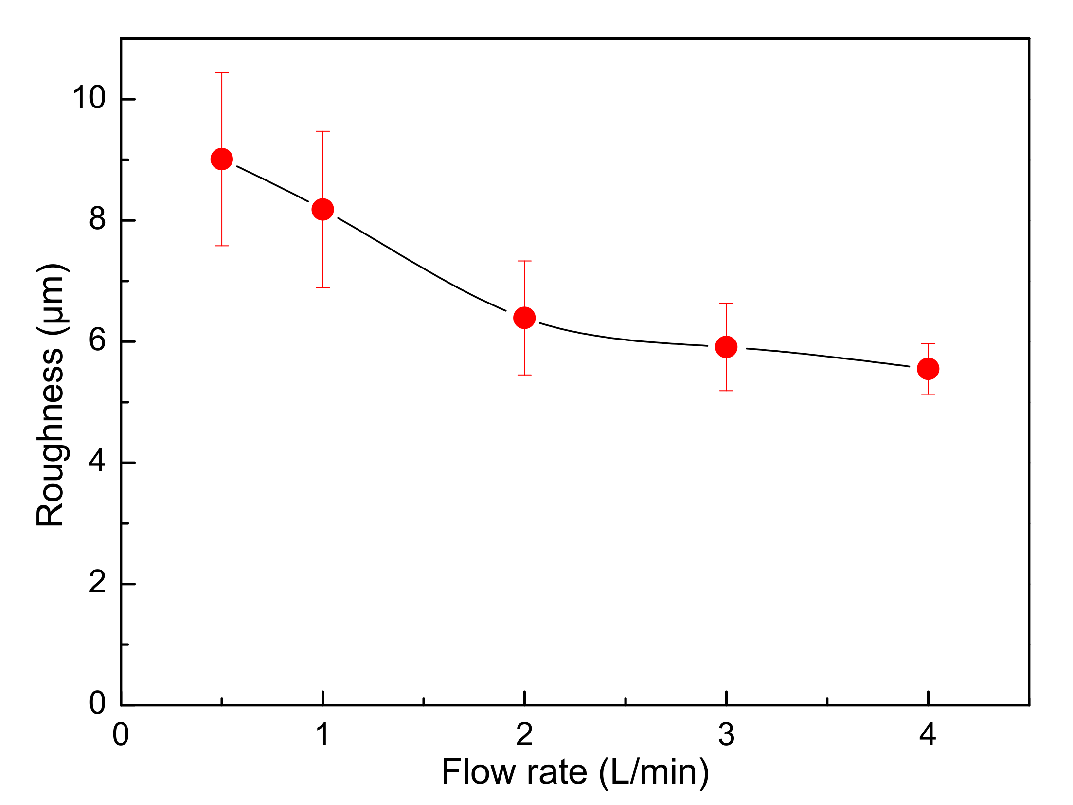
In the single-side jet inlet mode, the fresh electrolyte was introduced directly between the anode and the cathode as a jet flow. The electrolyte circulation rate has a great influence on the surface roughness of cathode copper, as can be seen from Figure 6. As the circulation rate increases from 0.5 L·min−1 to 4.0 L·min−1, the surface roughness decreases obviously from 6.86 μm to 2.97 μm, and the standard deviation drops sharply from 2.43 μm to 0.23 μm. It can thus be concluded that the jet flow is able to improve the cathode quality effectively compared with the conventional inlet mode (see Figure 5) during copper electrorefining at high current density.
Figure 7 illustrates the variation in the surface roughness of cathode copper at different electrolyte circulation rates. In the single-side jet inlet mode, the surface roughness is small at the center of the cathode copper and gradually increases towards both ends when the circulation rate is less than 2.0 L·min−1. This is because the agitation range of the jet flow is limited when the circulation rate is low, thus the jet flow has a large effect on the surface quality at the center of the cathode copper and has little influence on that at both ends. As a consequence, the closer the position at the surface of the cathode copper is to the jet region, the more flat the cathode copper surface, and vice versa, as shown in Figure 8. As the circulation rate increases, the unevenness of the surface roughness of cathode copper gradually decreases and almost disappears at 4.0 L·min−1.
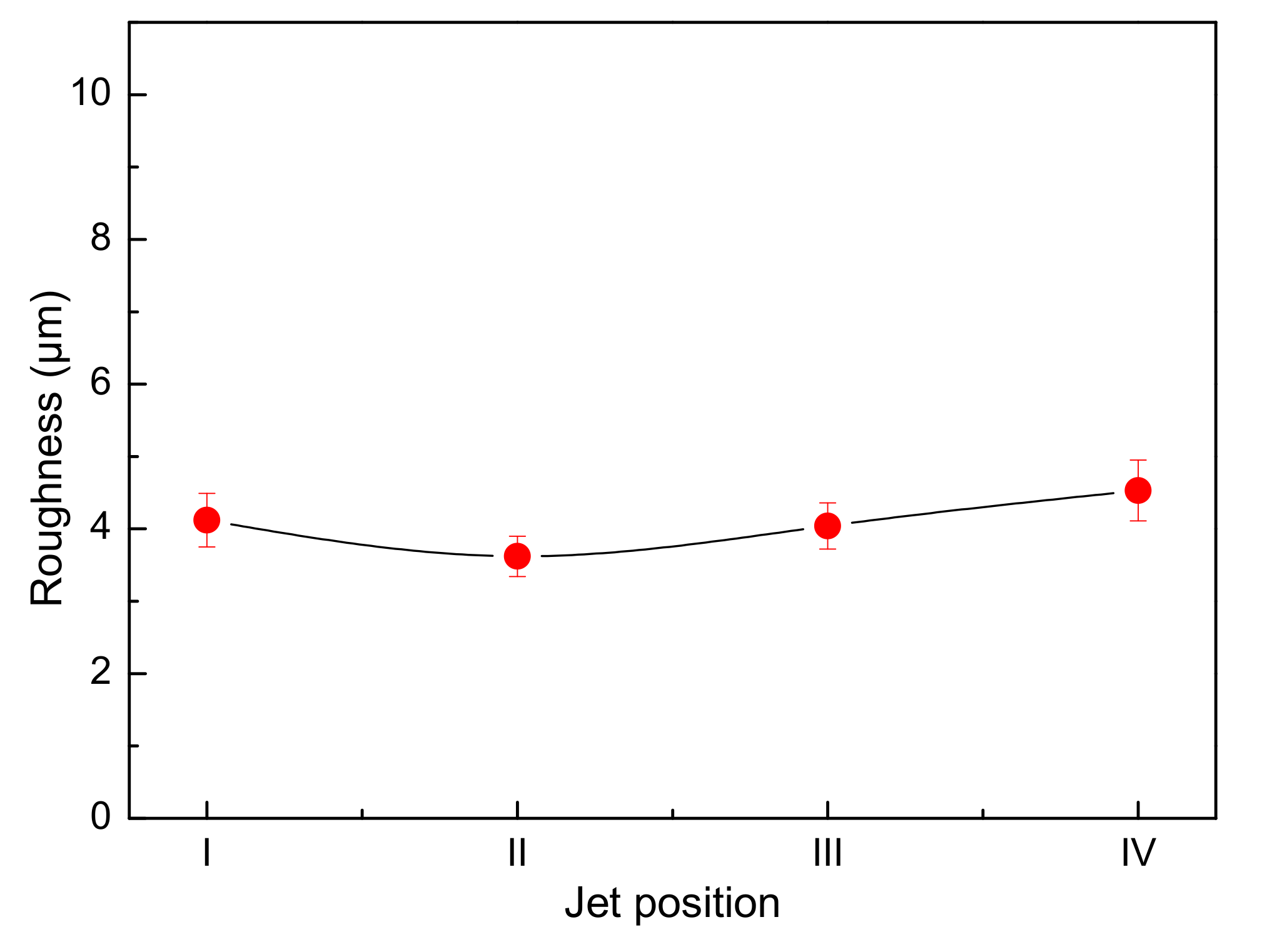
In the single-side jet inlet mode, the effect of the jet position on the surface roughness of cathode copper is as shown in Figure 9. The cathode quality is the best at the No. ii nozzle (the surface roughness is 3.62 μm and its standard deviation is 0.28 μm), and it is the worst at the No. iv nozzle (the surface roughness is 4.53 μm and its standard deviation is 0.42 μm). The mechanism of the influence of jet position on the cathode quality has to be found by analyzing both the electrolyte flow behavior and the thickness of the diffusion boundary layer on the electrode surface. In our future study, we will perform numerical simulations to reach these aims.
4. Conclusions
In this paper, the effects of the electrolyte inlet mode, the electrolyte circulation rate, and the position of the jet on the surface quality of the cathode copper were investigated experimentally during copper electrorefining at high current density. The following conclusions were reached.
- In the conventional bottom-inlet/top-outlet mode, an increase in electrolyte circulation rate has a limited effect on the decrease of the surface roughness of cathode copper.
- When a jet flow is introduced between the cathode and the anode, the electrolyte circulation rate has a large influence on the surface roughness of cathode copper, and the two are negatively related. When the circulation rate is small, the surface roughness of cathode copper is not uniform. The closer the position at the surface of the cathode copper to the jet region, the flatter the surface of the cathode copper, and vice versa.
- In the single-side jet inlet mode, when the jet position is at the middle height of the cathode deposition zone, the cathode quality is the best.
Author Contributions
All authors conceived and designed the experiments. H.W. and B.R. performed the experiments. H.W., W.X. and B.R. analyzed the data. H.W. wrote the paper. Q.W., W.X. and B.R. reviewed and edited the paper. H.W., W.X. and B.R. acquired the funding.
Funding
This research was funded by the National Natural Science Foundation of China, grant number 51674057; the Chongqing Research Program of Basic Research and Frontier Technology, grant numbers cstc2016jcyjA0142 and cstc2017jcyjAX0236; the Scientific and Technological Research Program of Chongqing Municipal Education Commission, grant numbers KJ1601326 and KJ1713343; and the Research Foundation of Chongqing University of Science & Technology, grant number CK2016B19.
Conflicts of Interest
The authors declare no conflicts of interest.
References
- Zhou, S. Electrolytic refining technology of high strengthen copper and production practice. Nonferrous Met. (Extr. Met.) 2013, 1–4. [Google Scholar] [CrossRef]
- Zheng, Y.; Zhao, P.; Wang, Y.; Lü, Z. Effect of electrorefining with high current density on cathode copper. J. Central South Univ. (Sci. Technol.) 2009, 40, 311–316. [Google Scholar]
- Kawai, S.; Miyazawa, T. CFD modelling and simulation of industrial-scale copper electrorefining process. Miner. Eng. 2014, 63, 81–90. [Google Scholar] [CrossRef]
- Zeng, W.; Free, M.L.; Wang, S. Simulation study of electrolyte flow and slime particle transport in a newly designed copper electrorefining cell. ECS Trans. 2016, 72, 23–42. [Google Scholar] [CrossRef]
- Zeng, W.; Wang, S.; Free, M.L. A comparative study of electrolyte flow and slime particle transport in a newly designed copper electrolytic cell and a laboratory-scale conventional electrolytic cell. JOM 2017, 69, 1876–1887. [Google Scholar] [CrossRef]
- Zeng, W.; Yi, G.; Wang, S.; Free, M.L. Design and analysis of direct side inflows in copper electrolytic cells by a computational method. Hydrometallurgy 2017, 169, 612–620. [Google Scholar] [CrossRef]
- Filzwieser, A.; Filzwieser, I.; Konetschnik, S. New technology for electrorefining of copper. JOM 2012, 64, 1290–1295. [Google Scholar] [CrossRef]
- Filzwieser, A.; Filzwieser, I.; Konetschnik, S.; Anzinger, A. Economic benefits of operating a copper electro-refining tankhouse at high current density using the Mettop-BRX Technology. In Proceedings of the Conference of Metallurgists (COM 2014), Vancouver, BC, Canada, 28 September–1 October 2014. [Google Scholar]
- General Administration of Quality Supervision; Inspection and Quarantine of the People’s Republic of China; Standardization Administration of the P.R.C. GB/T 665-2007 Chemical Reagent—Copper (II) Sulfate Pentahydrate; Standards Press of China: Beijing, China, 2007.
- Li, M.; Huang, J.; Tong, C.; Zhang, W.; Zhou, J.; Li, H.; Zhang, P. Numerical simulation of electrolyte flow in copper electrolytic cell. Chin. J. Nonferrous Met. 2015, 25, 2259–2267. [Google Scholar] [CrossRef]
Figure 1.
Schematic diagram of the experimental apparatus for copper electrorefining in (a) conventional bottom-inlet/top-outlet mode and (b) single-side jet inlet mode. 1, plastic barrel; 2, heating belt; 3, electrolyte outlet; 4, anode; 5, cathode; 6, electrolytic cell; 7, electrolyte; 8, pump; 9, electrolyte inlet; 10, electrically powered stirrer; 11, thermometer; 12, nozzle; 13, reservoir (Unit: mm).

Figure 2.
Measurement position of the surface roughness and morphology of cathode copper (Unit: mm).
Figure 2.
Measurement position of the surface roughness and morphology of cathode copper (Unit: mm).
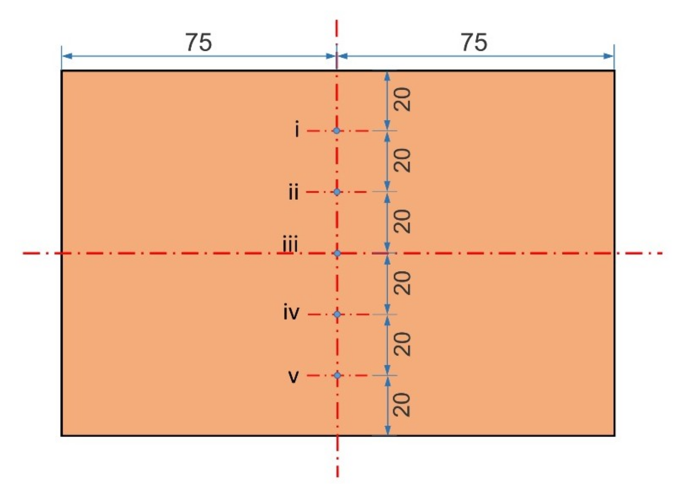
Figure 3.
Effect of electrolysis time on the surface roughness of cathode copper in the conventional inlet mode. Bars represent standard deviation. The electrolyte circulation rate was 1.0 L·min−1.
Figure 3.
Effect of electrolysis time on the surface roughness of cathode copper in the conventional inlet mode. Bars represent standard deviation. The electrolyte circulation rate was 1.0 L·min−1.

Figure 4.
Surface morphology of cathode copper for different electrolysis times in the conventional inlet mode: (a) 1 h; (b) 3 h; (c) 4 h; (d) 5 h. The SEM (Scanning Electron Microscope) sampling was at the No. iii position of the cathode copper as shown in Figure 2 and the electrolyte circulation rate was 1.0 L·min−1.

Figure 5.
Effect of electrolyte circulation rate on the surface roughness of cathode copper in the conventional inlet mode. Bars represent standard deviation.
Figure 5.
Effect of electrolyte circulation rate on the surface roughness of cathode copper in the conventional inlet mode. Bars represent standard deviation.

Figure 6.
Effect of electrolyte circulation rate on the surface roughness of cathode copper. Bars represent standard deviation. The position of the single-side jet inlet was at the No. ii nozzle as shown in Figure 1b.
Figure 6.
Effect of electrolyte circulation rate on the surface roughness of cathode copper. Bars represent standard deviation. The position of the single-side jet inlet was at the No. ii nozzle as shown in Figure 1b.

Figure 7.
Profile of the surface roughness at different positions of the cathode copper for various electrolyte circulation rates. The position of the single-side jet inlet was at the No. ii nozzle as shown in Figure 1b.
Figure 7.
Profile of the surface roughness at different positions of the cathode copper for various electrolyte circulation rates. The position of the single-side jet inlet was at the No. ii nozzle as shown in Figure 1b.
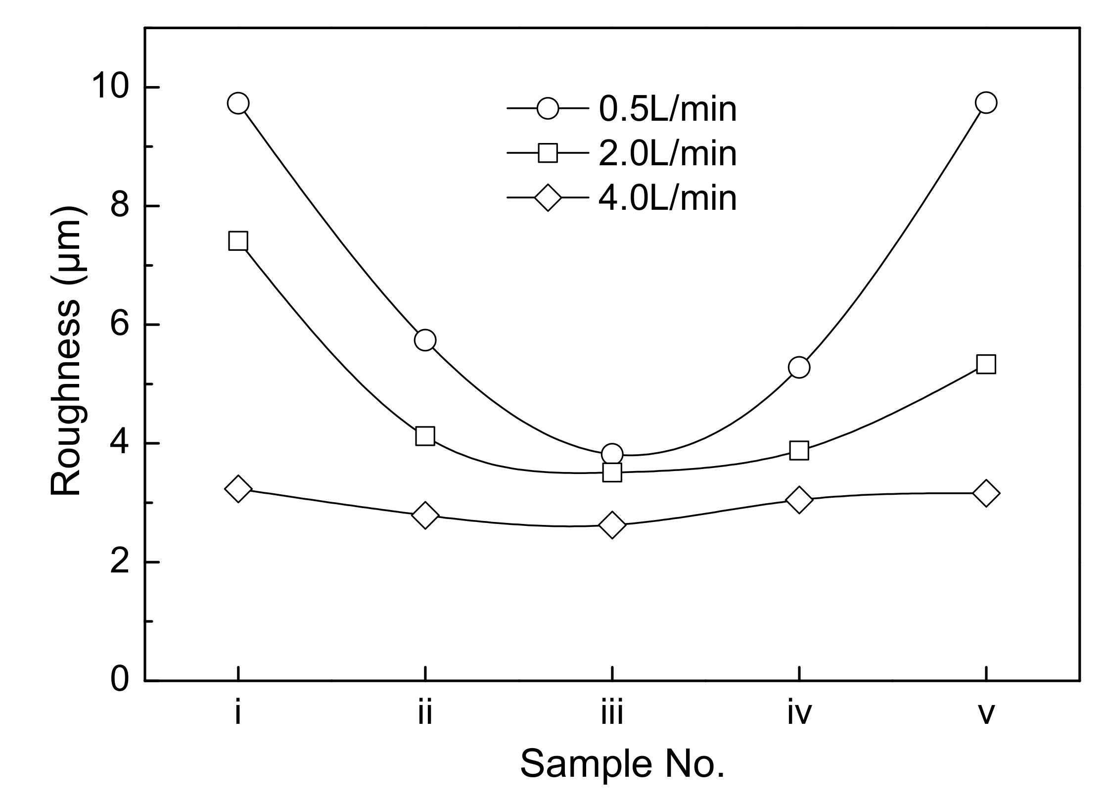
Figure 8.
Surface morphology of cathode copper for different electrolyte circulation rates: (a,b) 0.5 L·min−1; (c,d) 2.0 L·min−1; (e,f) 4.0 L·min−1. The position of the single-side jet inlet was at the No. ii nozzle as shown in Figure 1b. The SEM samplings of (a,c,e) were at the No. i position of the cathode copper, and the SEM samplings of (b,d,f) were at the No. iii position of the cathode copper, as shown in Figure 2.

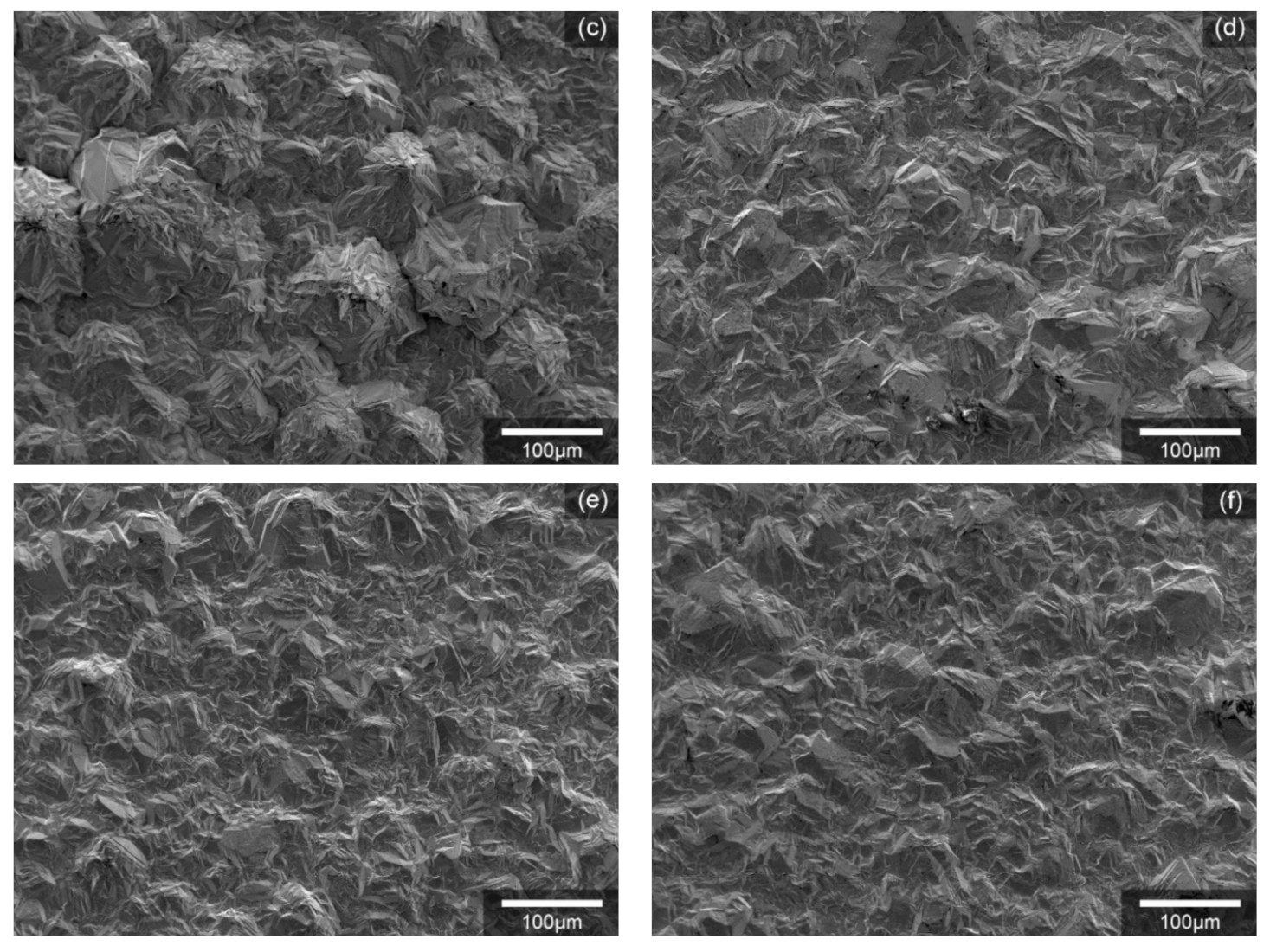
Figure 9.
Effect of jet position on the surface roughness of cathode copper in the single-side jet inlet mode. Bars represent standard deviation. The electrolyte circulation rate was 3.0 L·min−1.
Figure 9.
Effect of jet position on the surface roughness of cathode copper in the single-side jet inlet mode. Bars represent standard deviation. The electrolyte circulation rate was 3.0 L·min−1.
© 2018 by the authors. Licensee MDPI, Basel, Switzerland. This article is an open access article distributed under the terms and conditions of the Creative Commons Attribution (CC BY) license (http://creativecommons.org/licenses/by/4.0/).
Share and Cite
MDPI and ACS Style
Wang, H.; Wang, Q.; Xia, W.; Ren, B. Effect of Jet Flow between Electrodes on the Cathode Quality in Copper Electrorefining with High Current Density. Metals 2018, 8, 833. https://doi.org/10.3390/met8100833
AMA Style
Wang H, Wang Q, Xia W, Ren B. Effect of Jet Flow between Electrodes on the Cathode Quality in Copper Electrorefining with High Current Density. Metals. 2018; 8(10):833. https://doi.org/10.3390/met8100833
Chicago/Turabian StyleWang, Hongdan, Qian Wang, Wentang Xia, and Bingzhi Ren. 2018. "Effect of Jet Flow between Electrodes on the Cathode Quality in Copper Electrorefining with High Current Density" Metals 8, no. 10: 833. https://doi.org/10.3390/met8100833
Note that from the first issue of 2016, this journal uses article numbers instead of page numbers. See further details here.