Roughness of Ploughshare Working Surface and Mechanisms of Wear during Operation in Various Soils


1
Department of Engineering of Renewable Energy Sources, Faculty of Environment Management and Agriculture, West Pomeranian Technological University in Szczecin, Papieża Pawła VI Street 1, 71-459 Szczecin, Poland
2
Department of Materials Science, Welding and Strength of Materials, Faculty of Mechanical Engineering, Wroclaw University of Science and Technology, Smoluchowskiego Street 25, 50-370 Wrocław, Poland
*
Author to whom correspondence should be addressed.
Metals 2018, 8(12), 1042; https://doi.org/10.3390/met8121042
Submission received: 9 November 2018
/
Revised: 30 November 2018
/
Accepted: 5 December 2018
/
Published: 8 December 2018
(This article belongs to the Special Issue Fatigue and Wear for Steels)
Abstract
:The condition of working surfaces of ploughshares used in two soils with different granulometric condition (one containing large portion of coarse fractions and one containing increased portion of fine fractions) was evaluated. The soil cultivated for the research was characterised by high moisture content. In the tests, divided ploughshares were used, composed of separate parts: a share-points and a trapezoidal part. The aim of the research was to determine, on the grounds of scanning microscopy of working surfaces and their roughness measurements, wear processes occurring during operation of the ploughshare. It was found from the scanning photography that the main mechanism for material wear in soils containing an increased portion of coarse grains was microcutting and grooving, but in soils containing increased portion of fine fractions, microcutting dominated. Surface roughness of ploughshares used in soil with increased portion of coarse grains was higher than that of ploughshares working in soil with higher portion of fine fractions. It was found by statistical analysis that in soil with an increased portion of coarse grains, values of the parameters Ra (arithmetical mean deviation of the assessed profile), Rt (maximum height of the profile), Rv (maximum valley depth) and Rp (maximum peak height), most often occurring on ploughshare rake face, were 1.13, 10.50, 7.60, 2.74 µm respectively and, in soil with an increased portion of fine fractions, these values were 0.80, 6.86, 4.78 and 2.32 µm respectively. On working surfaces of ploughshares operating in both types of soil, higher values Rv in relation to Rp were found. In average, ratio of these parameters for ploughshares in both soils was ca. 2.7. This indicated that microcutting and scratching occurred in the process of material wear of a ploughshare.
1. Introduction
Abrasive wear belongs to dominating and commonly occurring processes of tribological wear [1]. With regard to agricultural machines, this is the direct cause of 75–80% of their operation shutdown [2], resulting in increased production costs [3]. Therefore, interest of the scientific community in the issues related to description and interpretation of the mechanisms of abrasive wear—not completely recognised so far—is fully justified. The so-far conducted research works were focused, among others, on taxonomy of this process [4,5,6,7,8,9,10,11,12,13,14], on development of its theoretical models [15,16,17,18] or on description of the mechanisms occurring at friction contact [19,20,21,22,23,24,25,26]. Of high importance are also works of utilitarian nature, oriented at evaluation of durability of the elements subjected to abrasive wear and working in specific conditions.
It should be said that, in the subject literature, some shortage exists of research works related to service conditions and concerning working elements of machines designed for cultivation of soil. In the papers related to this topic, complexity of interactions between soil abrasive medium and working elements operating in soil is emphasised, indicating the necessity of conducting tests in field conditions [27,28]. Laboratory experiments dominating in research practice are questionable with regard to their usable results, since their execution way often declines from real conditions of operation of tillage machines. The conditions closest to reality are simulation examinations with use of abrasive material imitating abrasive soil mix [29,30]. In the tests carried-out with the above-mentioned methods, the obtained results cannot be directly related to real conditions existing in service of working elements operating in soil. However, generalising conclusions about nature of the abrasive wear process can be drawn on their grounds. It was found that intensity of this process is dependent on the relation between hardness of abrasive material (Ha) and hardness of the wearing material (Hs) [31,32,33,34,35,36,37]. It was shown that, at comparable values of Ha and Hs, abrasive-wear rate is limited [38]. In turn, higher intensity of wear resulting from plastic deformation of surface layer was observed at the relation Ha/Hs > 1.2 and lower intensity of the process, named the so-called soft wear, was observed at Ha/Hs < 1.2. It was indicated in numerous papers that the process rate is affected by shape and size of abrasive particles [22,39,40,41,42,43,44,45], as well as by properties of the abraded material but mainly hardness and resistance to cracking of the abraded material is mostly considered [12,46,47]. In the case of materials with multi-phase structure like sintered carbides, it was shown that the wear process depends on granulation of these materials and on the phenomena resulting in destruction of soft matrix, connecting intensity of their loss with sizes of abrasive particles [45,48,49,50,51,52].
Loss of mass and change of dimensions of parts working in soil are resultants of elementary processes occurring in microscale: microcutting, scratching, grooving and also spalling of hard material particles [53,54]. Microcutting occurs, when destruction of the material subjected to wear is connected with creation of microchips with their volume corresponding to volume of the created scratches [18,22]. At grooving, multiple plastic deformations of the same material volume occur in the friction contact zone, resulting in separation of the weakened material [55]. At scratching however, material is partially separated in form of chips and partially displaced to sides of the created scratches.
It should be emphasised that elementary processes of abrasive wear, taking place during operation of working elements in soil, are determined also by interactions occurring in the friction contact zone, among others by relative speed of abrasive particles, values of their transmitting forces [42] and also by action of hydrogen, related to acidity of soil [56,57]. The mentioned conditions influence dynamics of the abrasion process and result in a big discrepancy between lifetimes of working elements. For example, various abrasive wear of ploughshares was shown in service tests, depending on grade and condition of cultivated soil [58].
The presented research, on the grounds of scanning microscopy and surface roughness measurements, was aimed at determination of state of working surfaces of ploughshare used for cultivation of two soils differing in granulometric composition and occurring abrasive wear mechanisms of ploughshare’s material.
2. Experiments
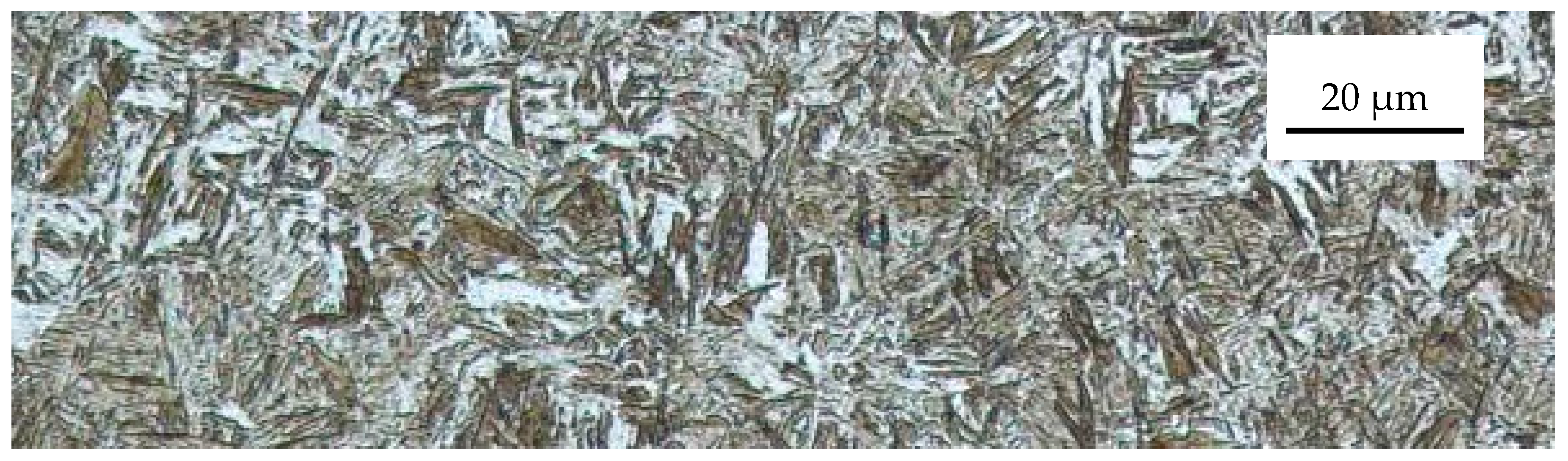
In the research, ploughshares not subjected to pad welding were used, composed of a separate share-point and a trapezoidal part, manufactured by a well-known global producer of agricultural equipment. The tools are made of boron steel and subjected to volumetric heat treatment. They are characterized by high resistance to wear and impact resistance and are commonly used in ploughs produced by the manufacturer in question. Ploughshares are made in several sizes, as well they can be subjected and not subjected to pad welding. Therefore, users of ploughs from this company have the option of selecting ploughshares in the context of their agricultural equipment and a planned tillage width. Chemical composition of steel of the ploughshares, its hardness are given in Table 1 while the microstructure are given in Figure 1.
Overall dimensions of the ploughshares are shown in Figure 2a. Microgeometry of working surfaces of ploughshares was measured with a profilographometer Hommel Tester T1000 on measuring lengths of 4.8 mm, acc. to EN 4288:2011. Locations of roughness measurement areas on rake faces of ploughshares together with their designations are also shown in Figure 2a. Positions of the measurement areas were determined using a template put on the rake faces. Roughness measurement were taken also in three places on ploughshare walls and in one place on flank faces of share-points (Figure 2b), three times in each measuring area. Surface roughness was described by arithmetical mean deviation of the roughness profile Ra, total height of the roughness profile Rt, maximum valley depth of the roughness profile Rv and maximum peak height of the roughness profile Rp. Because of small width of flank faces of trapezoidal parts of ploughshares, roughness was not measured on this surface. It should be added that the parameters Rt, Rv and Rp apply to single, extreme points of the surface profile on the measuring section. However, the Ra parameter assumes all measurement points, hence the extreme deviations of the profile from the middle line (deep scratches, protrusions) are averaged in the Ra parameter. Therefore, the Ra parameter can be used to assess the surface condition, which occurred in this research, while Rv and Rp are particularly useful for identifying elementary mechanisms of wear.
For values of the parameters Ra, Rt, Rp and Rv determined on rake face, the significance t-Student tests (significance level α = 0.05) were performed. The significance of differences between average values describing roughness of whole rake faces of ploughshares used under the conditions A and B was verified. An identical statistical test was performed for average values describing roughness of share-points and trapezoidal parts used under the same soil conditions. For the obtained measurement results, distribution analysis was carried-out with determination of modal values.
Qualitative evaluation of working surfaces of ploughshares was carried-out on the grounds of their surface observation in six measurement points (Figure 2b) using a scanning electron microscope (SEM) JEOL JSM-5800LV (JEOL Ltd., Tokyo, Japan) coupled with an X-ray microanalyzer Oxford LINK ISIS-300 (Oxford Instruments, Abington, UK).
The examined elements were used under two service conditions designated A and B. In both circumstances, elements were used for approximately two shifts, that is, ca. 16 h. Estimated sliding distance during that time was ca. 140 km. On the cultivated fields, no post-harvest tillage was carried-out before. Data about working conditions of the examined elements are given in Table 2. The conditions A and B were to a large extent similar with respect to actual humidity of soil, its volumetric density, firmness, ultimate shearing stress and reaction, as well as working depth of the ploughshare. Attention should be drawn to high content of water in soil during operation of the ploughshares. However, operating conditions of the ploughshares differed in contents of stones in soil, speed of plough operation (resulting from application of tractors with different power in tillage units) and also, which was the Authors’ intention, in granulometric composition of the cultivated soil. Under the conditions A, sand fraction dominated in soil (sand—70.6%, silt—25.5%, clay—3.9%) but under the conditions B, the cultivated soil was characterised by increased portion of dusty fraction (sand—52.4%, silt—39.7%, clay—7.9%). In addition, smaller portions of very coarse, coarse and medium sand (0.25–2 mm) occurred under the conditions B, see Table 2. So, under these conditions, soil contained larger portion of fine fraction than soil under the conditions A.
Measurements of soil granulation were carried-out by aerometric Casagrande’s method modified by Prószyński. Percentage of gravel in soil was determined by sieving method. Percentage of fine stones was determined by selecting stones from 1 m2 of arable layer. Quantity of large stones was determined on the grounds of trip number of the mechanisms protecting the plough bodies from overload during tillage of a determined field area. Humidity and volumetric density of soil was determined using 100-cm3 Kopecky’s cylinders, by the drying and weighing method. Firmness of soil was determined with a spring meter, using a cone dia. 16.5 mm with the apex angle 30°. Shearing stresses were measured with a vane rotary tester Geonor H-60 (Geonor Inc., Augusta, Me, USA), equipped with a cross 20 mm wide and 40 mm high. Depth of tillage was determined acc. to the guidelines in PN-90/R-55021. Tillage speed was determined by measuring the cultivator travel time on the distance of 50 m.
3. Results
The roughness parameters of surface of ploughshare non-cultivated in soil that was used under the condition A were for the share-point: Ra = 9.64 µm (standard deviation s = 1.15 µm), Rt = 58.03 µm (s = 4.92 µm), Rv = 25.15 µm (s = 4.63 µm), Rp = 32.89 µm (s = 5.87 µm) and for the trapezoidal part: Ra = 2.30 µm (s = 0.30 µm), Rt = 16.20 µm (s = 2.89 µm), Rv = 9.12 µm (s = 1.85 µm), Rp = 7.09 µm (s = 1.10 µm). However, in the case of ploughshare used under the condition B these parameters for the share-point were: Ra = 7.29 µm (s = 1.01 µm), Rt = 42.70 µm (s = 4.78 µm), Rv = 22.20 µm (s = 4.55 µm), Rp = 20.50 µm (s = 4.55 µm) and for the trapezoidal part: Ra = 2.38 µm (s = 0.03 µm), Rt = 16.42 µm (s = 2.18 µm), Rv = 8.06 µm (s = 1.08 µm), Rp = 8.37 µm (s = 1.37 µm). Therefore, the initial state of microgeometry of the surface of tested ploughshares was similar, while the trapezoidal parts were characterized by a lower roughness than the share-points.
Figure 3 shows values of Ra parameter determined in selected measurement places of rake faces of ploughshares used under the conditions A and B. Standard deviation for the given Ra parameter values was in the range s = 0.02–0.49 μm. Values of this parameter averaged in the measuring lines 1, 2, 3, 4 and 5 are also presented. Figure 4 gives information about distribution of Ra, Rt, Rp and Rv values occurring on rake surfaces of ploughshares. With the conditions A and B of ploughshares use, the analysis was performed for individual parameters at the same length of class intervals. However, Table 3 gives Ra, Rt, Rp and Rv values averaged for rake faces in individual measurement lines (lines 1, 2, 3, 4 and 5) together with ranges of these parameters. These values, determined for ploughshare wall surfaces and flank faces of share-points, are shown in Figure 5.
Graphic comparison of roughness measurement results (Figure 3) indicates, especially under the conditions A, higher Ra values for rake face of trapezoidal part than for share-point of a ploughshare. Statistical analysis showed that, under the conditions A, average values of roughness parameters Ra, Rt, Rp and Rv of rake faces were significantly larger for trapezoidal parts than those for share-points. In the case of ploughshares used under the conditions B, average values Ra and Rv of rake faces were significantly larger for trapezoidal parts than those for share-points, while no significant differences were found for average values Rp and Rt.
Roughness measurements averaged in the lines 1, 2, 3, 4 and 5 indicate generally higher roughness of rake faces of ploughshares working under the conditions A. Average values Ra determined for the lines 1, 2, 3, 4 and 5 under the conditions A were respectively ca. 1.2, 1.7, 1.1, 1.5 and 1.9 times larger than those under the conditions B. Average values Rt and Rp for the lines 1, 2, 3, 4 and 5 were also in most cases larger for the conditions A (Table 3). Attention should be paid to the fact that the values Rv, within the parameter Rt, were larger than the values Rp. This regularity was observed under both conditions A and B. Under both conditions, the value Rt was on the average ca. 2.7 times larger than the value Rp: from ca. 2.09 to 3.28 times for the conditions A and from 2.40 to 3.25 times for the conditions B (determined on the grounds of the ratios of average Rv to average Rp in individual measurement lines, see Table 3).
Even if statistical differences were found in surface roughness of share-points and trapezoidal parts of ploughshares working under the same conditions, it was decided that the relationships between roughness values of rake faces of ploughshares working under various soil conditions will be established on the grounds of measurements taken on entire surfaces of rake faces. The decision was motivated by the assumption that the rake face presents one total working surface of a ploughshare in spite of its constructional division to share-point and trapezoidal part. Significant differences were found between average values Ra, Rt and Rp under the conditions A and B, with smaller roughness of ploughshares used under the conditions B. Surface of the ploughshare used under conditions B showed also smaller average Rv value than that of the ploughshare used under conditions A, although this difference was not statistically significant (p = 0.09).
Between the conditions A and B, the differences in the roughness of the surface at the measuring points on the wall and the flank face were also statistically significant (Figure 2—places a, b, c and d). This applied to all roughness parameters.
Analysis of histograms of the values Ra, Rt, Rv and Rp measured on rake face of the ploughshare (Figure 4) shows asymmetrical distribution of the parameters. This is confirmed by discrepancies between average values of these parameters and dominating values estimated on the grounds of the data shown in histograms, see Figure 4. Especially big difference between the average and the dominating values of Rv was found under the conditions B. This asymmetry of distribution influenced values of standard deviation and, in consequence, could contribute to results of the significance test in that no significant differences were found between average Rv values under the conditions A and B.
It should be also emphasised that, in all measurement points located on surfaces of ploughshare walls and flank faces of share-points, Ra values were from ca. 1.3 to 2.7 times larger for the conditions A than for the conditions B. Under the conditions A, the values Rt, Rv and Rp were also larger, see Figure 5.
Defects on the rake face surfaces of ploughshares (unetched, SEM) after their operation under the conditions A and B are identified in Table 4. The state of these surfaces is shown in Figure 6, Figure 7, Figure 8, Figure 9, Figure 10, Figure 11, Figure 12 and Figure 13. (share-points in Figure 6 and Figure 7 and trapezoidal parts in Figure 8, Figure 9, Figure 10, Figure 11, Figure 12 and Figure 13). However, due to the large number of obtained results, only figures from the representative measurement places shown in Figure 2b have been shown.
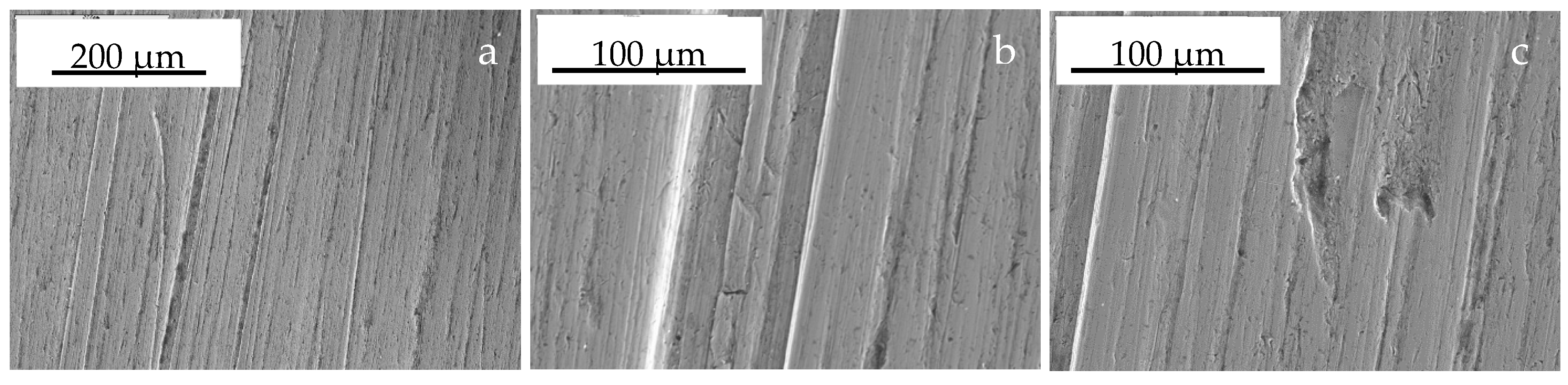
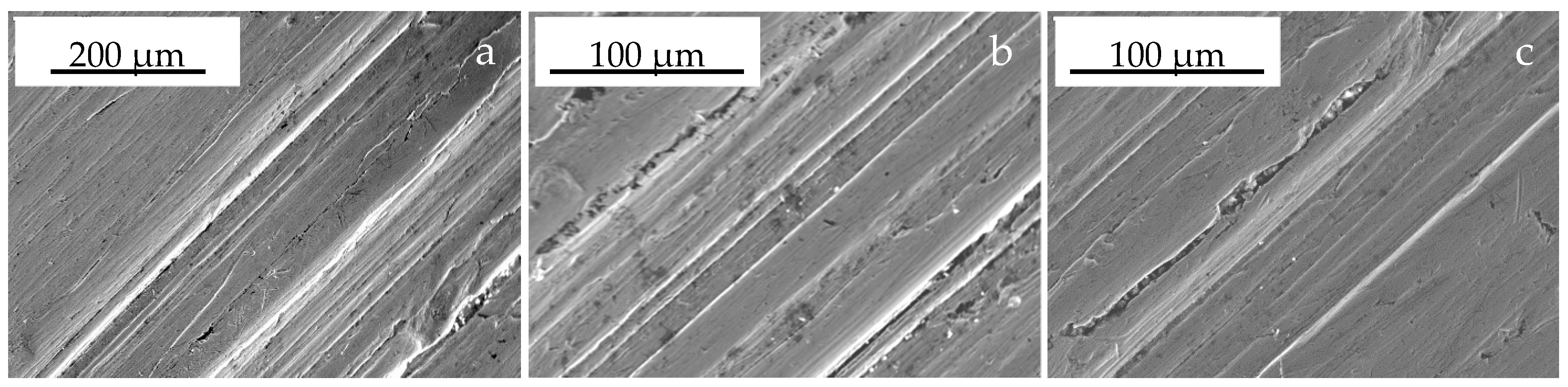
Under the conditions A (Figure 6, Figure 8, Figure 10 and Figure 12), the basic abrasive-wear processes of the ploughshare material are microcutting and grooving that initially result in plastic deformation of surface layer and next in upsetting of the material on edges of the created grooves. It is only as a result of material fatigue that the material accumulated at the edges is separated from the surface, which could cause cracks with trapped abrasive particles. Additional cracks were observed at bottoms of the created grooves (Figure 8a), which can evidence fatigue processes occurring concurrently. Scratches and grooves are most often parallel to each other, arranged along the direction of displacement of abrasive particles on metal surface. However, places with dominating grooving or microcutting can be distinguished on the surface. Scratches are narrow and deep but grooves are wide. Impact-abrasive nature of wear is evidenced by presence of pinholes (see Figure 6c and Figure 10c) created by bigger soil particles striking at larger angles. The so created pinholes were not very numerous and upset material not plastically deformed was observed on their edges. This material was probably torn off as a result of fatigue processes. Trapped abrasive particles were observed in smaller pinholes.
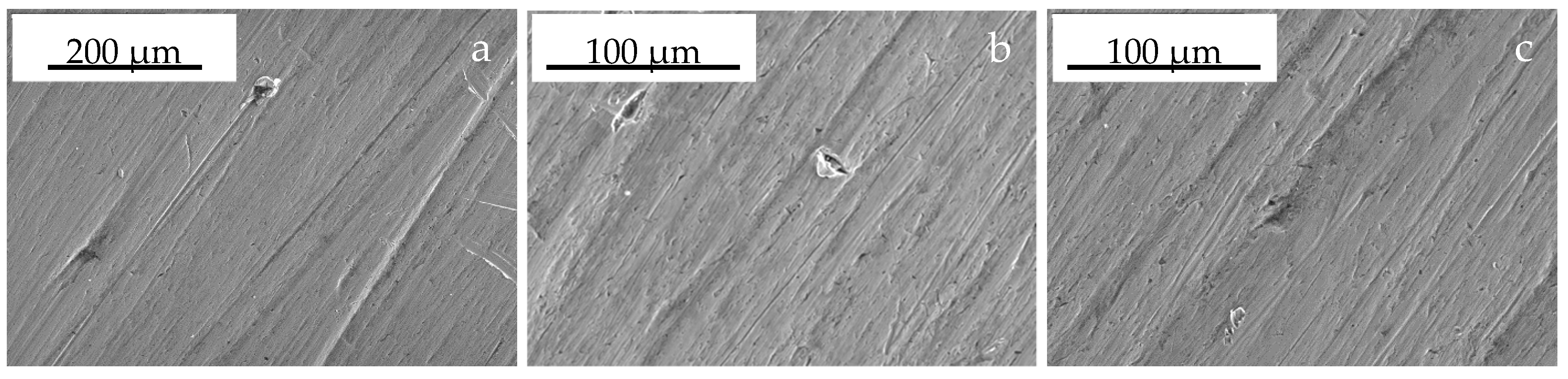
Scratches and grooves observed on rake face of the ploughshare working under the conditions B (Figure 7, Figure 9, Figure 11 and Figure 13) are shorter and narrower than those created under the conditions A. Pinholes on the surface are smaller but more numerous and, moreover, abrasive particles trapped inside can be seen. Here, microcutting is the dominating mechanism of wear. Arrangement of the scratches can prove impact nature of fine abrasive particles striking against the surface at big angles, see Figure 7a,c and Figure 13c. It did not cause long scratches, since the particles that collected the ploughshare material losing their speed were mostly removed from the surface together with metallic chips. Larger particles clearly scratched the material and displaced it towards front edge of the so created scratch, resulting in its upset (Figure 11a). Thus, the scratch was deeper and longer. These phenomena caused formation of grooves with pronounced lips at the rear end. Abrasive particles can also cause surface fatigue, resulting finally in detachment of parts of these lips. Among numerous fine scratches, larger grooves with clearly plastically deformed material can be observed on their edges (Figure 9c). However, grooving is the wear mechanism that occurred less intensively in the case of ploughshares working under the conditions B.
4. Discussion
Working elements of the agricultural machines, designed for operation in soil, are subjected to impact-abrasive wear. This type of wear is characterised by microcutting, grooving and plastic deformation of metal in form of dents. When soil particles are very large, material is destroyed by spalling or peeling.
In the case of carried out research, the roughness of the working surface of ploughshares after their use in the soil was clearly lower in relation to the initial state. Therefore, as a result of wear-related impact of soil grains, the initial state of microgeometry of the working surface of the ploughshare has been transformed into a state adequate to the given conditions of use of the elements.
On the rake face of the trapezoidal part, the deep scratches were observed, which in the case of the share-point were not so numerous. Figure 14 presents examples of roughness profiles illustrating the described microgeometry state of these surfaces together with the values of parameters corresponding to these profiles. The selected roughness profiles of the ploughshares operating in conditions A and B relate to the same measurement places. The qualitative assessment of profiles and values of surface roughness parameters clearly indicate a greater surface roughness of the trapezoidal parts in relation to the surface roughness of the share-points. The presented summary of selected results was confirmed by a significance test, which concerned all measurements made for the trapezoidal part and share-point of ploughshare (see the section “Results”). The occurrence of deep scratches on the rake surface of the trapezoidal part was an obvious reason for increasing the value of parameters characterizing the state of its microgeometry. The scratches probably arose as a result of the interaction of large-size soil fractions (stones, gravel). Large soil particles, despite the lower soil pressure on the rake surface of the trapezoidal part than on the surface of the share-point, may retain the ability to destructively affect the material of ploughshare. Probably, these scratches are slowly removed as a result of the impact of fine soil particles, whose ability to wear of the material at lower pressures is limited. However, the greater soil pressure exerted on the surface of the share-point favours the intensification of the wear effect of fine soil particles, which results in faster removal of scratches from the surface, so the microgeometry state of the share-point surfaces is probably more strongly determined by fine soil particles. Issues concerning roughness measurements of working elements operating in soil are not generally undertaken in the literature of the subject. In previous studies [59], the authors determined the mean roughness of the rake face surface of ploughshares made of martensitic and pearlitic steel. Roughness parameters values = determined in these tests for ploughshares made of martensitic steel (share-point: Ra = 0.79 μm, Rt = 9.41 μm, Rv = 6.85 μm, Rp = 2.56 μm, trapezoidal part: Ra = 0.76 μm, Rt = 9.19 μm, Rv = 6.59 μm, Rp = 2.60 μm) are comparable with the measurement results presented in this research. In both tests, the hardness of martensitic steel was basically the same. In the case of ploughshares made of pearlitic steel, for Ra, Rt and Rp parameters, the roughness of their surface was statistically significantly higher (from 1.3 to 1.9 times), which was due to the lower (1.8 times) hardness of pearlitic steel in relation to the hardness of martensitic steel.
Qualitative analysis performed on the grounds of SEM observations revealed differences in abrasive-wear mechanisms between different working conditions of the examined ploughshare. Under the conditions A, with higher portion of large soil particles (gravel 2.0 to 3.0 mm, very coarse sand 1.0 to 2.0 mm, coarse sand 0.5 to 1.0 mm, medium sand 0.25 to 0.5 mm, fine sand 0.10 to 0.25 mm), the main wear mechanism was microcutting and grooving. Under the conditions B however, with higher portion of fine soil particles (very fine sand 0.05 to 0.10 mm, silt 0.05 to 0.002 and clay below 0.002 mm), the dominating wear mechanism was microcutting, then grooving to a smaller extent but fine and short scratches were most probably created as a result of interaction with large soil particles, that is, gravel grains. No differences were observed in wear mechanisms between share-points and trapezoidal parts working under the same soil conditions.
It should be added that conditions of the compared ploughshares could be influenced by small stones present under soil conditions A, as well as 1.35 times lower tillage speed under the conditions B, see Table 2.
The qualitative statements of SEM analysis are confirmed by roughness measurements of working surfaces of the examined ploughshares.
Under the conditions A, characterised by higher portion of large soil grains that is, gravel and sand 2—0.1 mm (Table 2) in relation to the conditions B, roughness of working surfaces was higher. This concerns surfaces of rake face, ploughshare wall and flank face of the share-point, and, basically, all the surface roughness parameters. For the rake face surface, statistically significantly higher roughness was found in the Ra, Rt and Rp parameters, while for the measuring places lying on the wall and the flank face - for Ra, Rt, Rv and Rp parameters. This indicates more intensive effect of soil on the ploughshare material under the conditions A.
Higher roughness of the ploughshare surface under the conditions A can be explained by higher portion of large particles whose effect on the ploughshare material was more intensive. In average, Ra values were ca. 1.5 times on rake face, ca. 2.3 times on ploughshare wall and ca. 1.3 times on flank face higher under the conditions A than under the conditions B. For the parameter Rt, these relations were 1.3, 2.0 and 1.4, respectively. More intensive wear under the conditions A is demonstrated also by distributions of Ra, Rt and Rv values—the ranges in that these parameters occurred most frequently were partially overlapped for the conditions A and B, while for the conditions A limits of the ranges were moved towards larger values. Of course, large grains also happened under the conditions B, influencing values of the parameters characterising condition of the ploughshare surface but at smaller number of such grains, working surfaces were mostly shaped by fine soil particles.
It can be supposed that wear mechanisms of the ploughshare were to a large extent influenced by increased humidity of the cultivated soil. Under such conditions, with plastic and susceptible soil, grains are not very firmly fastened by neighbouring particles, which restricts possibilities of destructive action of soil grains on the ploughshare material. Weakly fastened particles, with smaller forces acting between them and the tool material, can be rolled or can lose contact with the material. So, under the experimental conditions, sliding distance and depth of action of soil grains on the tool material could be smaller. This resulted in less intensive wear under both A and B conditions, as well as in closer effects of two soils differing in granulation.
High plasticity of soils with increased humidity could also affect relatively small diversity of roughness on working surface of the ploughshare. Occurrence of wear or elastic or plastic deformation connected with grooving requires that hard soil particles move over surface of the working element and exert pressure against this surface. However, during the experiments, soil particles probably lost their contact with the ploughshare material more easily, which could reduce effects of pressure exerted by soil in some areas of the ploughshare surface.
It should be added that fastening of large grains, especially in dry soil, is stronger than fastening of smaller grains. Thus, abrasibility of large grains is higher. It seems that differences in conditions of the ploughshare working surfaces would be bigger, if the tool worked in soils with lower humidity and identical granularity. Of course, this should be confirmed experimentally.
It should be also added that larger values Rv than Rt (their average ratio on rake faces was ca. 2.7) occurring under both A and B conditions indicate participation in the wear process of ploughshares such forms of wear at that material is separated and therefore occurrence of microcutting and scratching.
The various mechanisms and intensity of wear of the ploughshare material depending on the working conditions are the reason for the occasional idea of designing and producing ploughshares for working in different soil conditions. However, such solutions are not used by producers of ploughshare who, considering the economic factor, usually strive to produce the best, wear-resistant and impact-resistant ploughshares. It is mainly a matter of choosing a material for ploughshares and their target hardness, whereby the high hardness of the ploughshare material increases their resistance to abrasive wear but also contributes to reducing the impact strength of the elements. As a consequence, the produced ploughshares achieve different durability depending on whether they are operated in more or less aggressive soil conditions, aggressiveness which is not only determined by the soil granulation but also to a very significant extent its humidity, which in individual agrotechnical seasons is a variable factor. It also seems that introducing by ploughshare producers in the material diversity of the product range would increase the organizational perturbations occurring in the production process and in the distribution of components.
5. Conclusions
- (1)
- In moist soils containing higher portion of large grains, the main mechanism of wear of ploughshare material is microcutting and grooving but in soils with increased content of fine fractions, the dominating wear mechanism is microcutting.
- (2)
- Roughness of working surfaces of the ploughshare operating in soil containing increased portion of large particles is higher than of the tool operating in soil containing larger portion of fine fractions. In the first case, roughness values were: Ra 1.13 μm, Rt 10.50 μm, Rv 7.60 μm and Rp 2.74 µm. In the second case, the values were 0.80, 6.86, 4.78 and 2.32 µm, respectively.
- (3)
- In both types of soils, higher Rv than Rp values (average ratio ca. 2.7) were found on working surfaces of the ploughshare. This indicates participation of microcutting and scratching in the wear process.
- (4)
- Results of profilographometric and SEM examinations deliver complementary information about condition of working surfaces of ploughshares: qualitative assessment is performed by SEM and quantitative assessment—by profilographometric measurements.
Author Contributions
T.S. and P.K.: conceived and designed the experiments; performed the experiments; analyzed the data; contributed reagents/materials/analysis tools; wrote the paper. B.B.: performed the experiments; analyzed the data; contributed reagents/materials/analysis tools; wrote the paper.
Conflicts of Interest
The authors declare no conflict of interest.
References
- Eyre, T.S. The mechanisms of wear. Tribol. Int. 1978, 11, 91–96. [Google Scholar] [CrossRef]
- Ikranov, V. Abrasive wear mechanism. In Proceedings of the 4th European Tribology Congress Eurotrib’85, Lyon, France, 9–12 September 1985; Volume 4, pp. 189–196. [Google Scholar]
- Nalbant, M.; Palali, A.T. Effects of different material coatings on the wearing of plowshares in soil tillage. Turk. J. Agric. 2011, 35, 215–223. [Google Scholar]
- Blickensderfer, R.; Madsen, B.W.; Tylczak, J.H. Comparison of several types of abrasive wear tests. In Proceedings of the International Conference Wear of Materials, Vancouver, BC, Canada, 14–18 April 1985; ASME: Vancouver, BC, Canada, 1985. [Google Scholar]
- Misra, A.; Finnie, I. A classification of 3-body abrasive wear and design of a new tester. Wear 1980, 60, 111–121. [Google Scholar] [CrossRef]
- Misra, A.; Finnie, I. A review of the abrasive wear of metals. J. Eng. Mater. Technol. 1982, 104, 94–101. [Google Scholar] [CrossRef]
- Burwell, J.T. Survey of possible wear mechanisms. Wear 1958, 1, 119–141. [Google Scholar] [CrossRef]
- Rabinowitz, E.; Mutis, A. Effect of abrasive particle size on wear. Wear 1965, 8, 381–390. [Google Scholar] [CrossRef]
- Toporov, G.V. The influence of structure on the abrasive wear of cast iron. Frict. Wear Mach. 1960, 12, 39–59. [Google Scholar]
- Avery, H.S. Classification and Precision of Abrasion of Materials; ASME: New York, NY, USA, 1977. [Google Scholar]
- Solski, P. Zużycie Cierne Metali; WNT: Warszawa, Poland, 1968. [Google Scholar]
- Zum Gahr, K.-H. Microstructure and Wear of Materials; Elsevier: Amsterdam, The Netherlands, 1987. [Google Scholar]
- Hawk, J.A.; Wilson, R.D.; Tylczak, J.H.; Doģan, Õ.N. Laboratory abrasive wear tests: Investigation of test methods and alloy correlation. Wear 1999, 225–229, 1031–1042. [Google Scholar] [CrossRef]
- Gates, J.D. Two-body and three-body abrasion: A critical discussion. Wear 1998, 214, 139–146. [Google Scholar] [CrossRef]
- Rabinowicz, E. Friction and Wear of Materials; John Wiley: New York, NY, USA, 1965. [Google Scholar]
- Evans, A.G.; Wildshaw, T.R. Quasi-static solid particle damage in brittle solids—I. Observations, analysis and implications. Acta Metall. 1976, 24, 939–956. [Google Scholar] [CrossRef]
- Kragelski, I.V.; Dobycin, M.N.; Kombalov, V.S. Osnovy racetov na trenie i iznos; Masinostrojenie: Moskva, Russia, 1977. [Google Scholar]
- Murray, M.J.; Mutton, P.J.; Watson, J.D. Abrasive wear mechanisms in steels. J. Lubr. Technol. 1982, 104, 9–16. [Google Scholar] [CrossRef]
- Hutchings, I.M. Tribology: Friction and Wear Engineering Materials; Edvard Arnold: London, UK, 1992. [Google Scholar]
- Davis, J.R. Surface Engineering for Corrosion and Wear Resistance; ASM International: Geauga County, OH, USA, 2001. [Google Scholar]
- Stachowiak, G.W.; Batchelor, A.W. Engineering Tribology; Butterworth-Heineman: Oxford, UK, 2005. [Google Scholar]
- Moore, M.A. Abrasive wear. In Treatise on Materials Science and Technology; Scott, D., Ed.; Academic Press: New York, NY, USA, 1979; pp. 217–257. [Google Scholar]
- Hokkirigawa, K.; Kato, K. An experimental and theoretical investigation of ploughing, cutting and wedge formation during abrasive wear. Tribol. Int. 1988, 21, 51–57. [Google Scholar] [CrossRef]
- Suh, N.P. The delamination theory of wear. Wear 1973, 25, 111–124. [Google Scholar] [CrossRef]
- Challen, J.M.; Oxley, P.L.B. An explanation of the different regimes of friction and wear using asperity deformation models. Wear 1979, 53, 229–243. [Google Scholar] [CrossRef]
- Lansdown, A.R.; Price, A.L. Materials to Resist Wear-Guide to Their Selection and Use; Pergamon Press: Swansea, Wales, 1989. [Google Scholar]
- Mann, P.S.; Brar, N.K. Tribological aspects of agricultural equipments: A review. Int. Res. J. Eng. Technol. 2015, 2, 1704–1708. [Google Scholar]
- Yu, H.-J.; Bhole, S.D. Development of a prototype abrasive wear tester for tillage tool materials. Tribol. Int. 1990, 23, 309–316. [Google Scholar] [CrossRef]
- Łabęcki, M.; Gościański, M.; Kapcińska, D.; Pirowski, Z. Badania tribologiczne, wytrzymałościowe i strukturalne wybranych materiałów stosowanych na elementy maszyn rolniczych pracujące w glebie. J. Res. Appl. Agric. Eng. 2007, 52, 43–51. [Google Scholar]
- Napiórkowski, J. Elementarne procesy zużywania tworzyw wielofazowych w piasku luźnym. Inżynieria Rolnicza 2010, 2, 71–77. [Google Scholar]
- Pirso, J.; Viljus, M.; Letunovitš, S.; Juhani, K.; Joost, R. Three-Body Abrasive wear of Cermets. Wear 2011, 271, 2868–2878. [Google Scholar] [CrossRef]
- Engqvist, H.; Axén, N. Abrasion of Cemented Carbides by Small Grits. Tribol. Int. 1999, 32, 527–534. [Google Scholar] [CrossRef]
- Tjong, S.; Lau, K. Abrasion resistance of stainless-steel composites reinforcedwith hard TiB2 particles. Compos. Sci. Technol. 2000, 60, 1141–1146. [Google Scholar] [CrossRef]
- Larsen-Basse, J.; Koyanagi, E.T. Abrasion of WC-Co alloysbyquartz. J. Lubr. Technol. 1979, 101, 208–211. [Google Scholar] [CrossRef]
- Tabor, D. The physical meaning of indentation and scratch hardness. Br. J. Appl. Phys. 1956, 7, 159. [Google Scholar] [CrossRef]
- Wahl, H. Verschleiß probleme in Braunkohlenbergbau. Braunkohle Wärme Energie 1951, 3, 75–87. [Google Scholar]
- Uetz, H.; Föhl, J. Gleitverschleißuntersuchungen an Metallen und nichmetallischen Hartstoffen unter Wirkung körniger Stoffe. Braunkohle Wärme Energie 1969, 21, 10–18. [Google Scholar]
- Richardson, R.C.D. The wear of metals by relatively soft abrasives. Wear 1968, 11, 245–275. [Google Scholar] [CrossRef]
- Deuis, R.L.; Subramanian, C.; Yellup, J.M. Three-body abrasive wear of composite coatings in dry and wet environments. Wear 1998, 214, 112–130. [Google Scholar] [CrossRef]
- Swanson, P.A.; Klann, R.W. Abrasive wear studies using the wet sand and dry sand rubber wheel tests. In Proceedings of the International Conference Wear of Materials, San Francisco, CA, USA, 30 March–1 April 1981; pp. 379–389. [Google Scholar]
- Woldman, M.; Heide, E.; Schipper, D.J.; Tinga, T.; Masen, M.A. Investigating the influence of sand particle properties on abrasive wear behavior. Wear 2012, 294–295, 419–426. [Google Scholar] [CrossRef]
- Woldman, M.; Heide, E.; Tinga, T.; Masen, M.A. The influence of abrasive body dimensions on single asperity wear. Wear 2013, 301, 76–81. [Google Scholar] [CrossRef]
- Sasada, T.; Oike, M.; Emori, N. The effect of abrasive grain size on the transition between abrasive and adhesive wear. Wear 1984, 97, 291–302. [Google Scholar] [CrossRef]
- Pellegrin, D.V.; Torrance, A.A.; Haran, E. Wear mechanisms and scale effects in two-body abrasion. Wear 2009, 266, 13–20. [Google Scholar] [CrossRef] [Green Version]
- Coronadoa, J.J.; Sinatorab, A. Effect of abrasive size on wear of metallic materials and its relationship with microchips morphology and wear micromechanisms: Part 1. Wear 2011, 271, 1794–1803. [Google Scholar] [CrossRef]
- Zum Gahr, K.-H. Modelling of two-body abrasive wear. Wear 1988, 124, 87–103. [Google Scholar] [CrossRef]
- Nganbe, M.; Khan, T.; Glenesk, L. High Wear Resistant HVOF Coatings for Use in the Oil and Sands Industry. In Proceedings of the Symposium on Materials Technology in Mechanical Engineering, Calgary, AB, Canada, January 2006. [Google Scholar]
- Larsen-Basse, J. Effect of hardness and local fracture toughness on the abrasive wear of WC-Co alloys. In Tribology—Friction, Lubrication and Wear, Fifty Years; Institution of Mechanical Engineers: London, UK, 1987; Volume I, pp. 277–282. [Google Scholar]
- Polak, R.; Ilo, S.; Badisch, E. Relation between inter-particle distance (LIPD) and abrasion in multiphase matrix-carbide material. Tribol. Lett. 2009, 33, 29–35. [Google Scholar] [CrossRef]
- Gee, M.G.; Gant, A.; Roebuck, B. Wear mechanisms in abrasion and erosion of WC/Co and related hardmetals. Wear 2007, 263, 137–148. [Google Scholar] [CrossRef]
- Wayne, S.F.; Baldoni, J.G.; Buljan, S.T. Abrasion and erosion of WC–Co with controlled microstructures. Tribol. Trans. 1990, 33, 611–617. [Google Scholar] [CrossRef]
- O’Quigley, D.G.F.; Luyckz, S.; James, M.N. An empirical ranking of a wide range of WC–Co grades in terms of their abrasion resistance measured by the ASTM standard B611-85 test. Int. J. Refract. Met. Hard Mater. 1997, 15, 73–79. [Google Scholar] [CrossRef]
- Hebda, M.; Wachal, A. Trybologia; WNT: Warszawa, Poland, 1980. [Google Scholar]
- Zum Gahr, K.-H.; Eldis, G.T. Abrasive wear of white cast irons. Wear 1980, 64, 175–194. [Google Scholar] [CrossRef]
- Ludema, K.C. A Perspective on Wear Models; ASTM Standardisation News: West Conshohocken, PA, USA, 1978; Volume 56, pp. 13–17. [Google Scholar]
- Napiórkowski, J.; Lemiecha, M.; Rosiak, M. An analysis of the impact of soil mass pH on the wear process of steel. In Proceedings of the MATEC Web of Conferences 2017 (94), The 4th International Conference on Computing and Solutions in Manufacturing Engineering 2016—CoSME’16, Braşov, Romania, 3–4 November 2016. [Google Scholar]
- Stabryła, J. Research on the degradation process of agricultural tools in soil. Problemy Eksploatacji 2007, 4, 223–232. [Google Scholar]
- Natsis, A.; Petropoulos, G.; Pandazaras, C. Influence of local soil conditions on mouldboard ploughshare abrasive wear. Tribol. Int. 2008, 41, 151–157. [Google Scholar] [CrossRef]
- Stawicki, T.; Białobrzeska, B.; Kostencki, P. Tribological Properties of Plough Shares Made of Pearlitic and Martensitic Steels. Metals 2017, 7, 139. [Google Scholar] [CrossRef]
Figure 1.
Microstructure of ploughshare material: martensitic steel with structure of medium-carbon, fine-acicular tempered martensite. Etched with 3% HNO3 (acc. to PN-H-04512-1975), light microscopy.
Figure 1.
Microstructure of ploughshare material: martensitic steel with structure of medium-carbon, fine-acicular tempered martensite. Etched with 3% HNO3 (acc. to PN-H-04512-1975), light microscopy.

Figure 2.
Places of roughness measurements (a) and of SEM observations (b); dimensions are given in “mm.”
Figure 2.
Places of roughness measurements (a) and of SEM observations (b); dimensions are given in “mm.”

Figure 3.
Average arithmetic deviation of roughness profile of ploughshare rake face in a given measurement place depending on working conditions.
Figure 3.
Average arithmetic deviation of roughness profile of ploughshare rake face in a given measurement place depending on working conditions.

Figure 4.
Histograms of Ra, Rt, Rv and Rp values measured on rake faces of ploughshares (—average value, s—standard deviation, D—mode).
Figure 4.
Histograms of Ra, Rt, Rv and Rp values measured on rake faces of ploughshares (—average value, s—standard deviation, D—mode).

Figure 5.
Surface roughness parameters of ploughshare walls and flank faces of share-points. Standard deviation values: for Ra: 0.07–1.18 µm, for Rt: 0.95–11.70 µm, for Rv: 0.54–8.38 µm and for Rp: 0.09–7.96 µm.
Figure 5.
Surface roughness parameters of ploughshare walls and flank faces of share-points. Standard deviation values: for Ra: 0.07–1.18 µm, for Rt: 0.95–11.70 µm, for Rv: 0.54–8.38 µm and for Rp: 0.09–7.96 µm.

Figure 6.
Surface of a fragment of share-point—conditions A, measurement place 2 acc. to Figure 2b: (a) general view; (b) parallel scratches and grooves; (c) scratches, grooves and fine pinholes.
Figure 6.
Surface of a fragment of share-point—conditions A, measurement place 2 acc. to Figure 2b: (a) general view; (b) parallel scratches and grooves; (c) scratches, grooves and fine pinholes.

Figure 7.
Surface of a fragment of share-point—conditions B, measurement place 2 acc. to Figure 2b: (a) general view; (b) fine, short scratches proving impact action of abrasive particles and fine pinholes; (c) fine scratches and deep, parallel scratches caused by larger abrasive particles.
Figure 7.
Surface of a fragment of share-point—conditions B, measurement place 2 acc. to Figure 2b: (a) general view; (b) fine, short scratches proving impact action of abrasive particles and fine pinholes; (c) fine scratches and deep, parallel scratches caused by larger abrasive particles.

Figure 8.
Surface of a fragment of trapezoidal part—conditions A, measurement place 3 acc. to Figure 2b: (a) general view; (b) scratches and a groove with crack on its bottom; (c) scratches and grooves, crack on the surface with trapped abrasive particles.
Figure 8.
Surface of a fragment of trapezoidal part—conditions A, measurement place 3 acc. to Figure 2b: (a) general view; (b) scratches and a groove with crack on its bottom; (c) scratches and grooves, crack on the surface with trapped abrasive particles.

Figure 9.
Surface of a fragment of trapezoidal part—conditions B, measurement place 3 acc. to Figure 2b: (a) general view; (b) scratches and fine grooves; (c) scratches, grooves and fine pinholes with trapped abrasive particles.
Figure 9.
Surface of a fragment of trapezoidal part—conditions B, measurement place 3 acc. to Figure 2b: (a) general view; (b) scratches and fine grooves; (c) scratches, grooves and fine pinholes with trapped abrasive particles.

Figure 10.
Surface of a fragment of trapezoidal part—conditions A, measurement place 4 acc. to Figure 2b: (a) general view, parallel scratches and grooves; (b) parallel scratches and grooves and pinhole with abrasive particles; (c) pinhole.
Figure 10.
Surface of a fragment of trapezoidal part—conditions A, measurement place 4 acc. to Figure 2b: (a) general view, parallel scratches and grooves; (b) parallel scratches and grooves and pinhole with abrasive particles; (c) pinhole.

Figure 11.
Surface of a fragment of trapezoidal part—conditions B, measurement place 4 acc. to Figure 2b: (a) general view; (b) scratches with plastically deformed material on their front faces; (c) scratches, grooves and fine pinholes with trapped abrasive particles.
Figure 11.
Surface of a fragment of trapezoidal part—conditions B, measurement place 4 acc. to Figure 2b: (a) general view; (b) scratches with plastically deformed material on their front faces; (c) scratches, grooves and fine pinholes with trapped abrasive particles.

Figure 12.
Surface of a fragment of trapezoidal part—conditions A, measurement place 5 acc. to Figure 2b: (a) general view; (b) scratches and grooves; (c) scratches, grooves and cracks.
Figure 12.
Surface of a fragment of trapezoidal part—conditions A, measurement place 5 acc. to Figure 2b: (a) general view; (b) scratches and grooves; (c) scratches, grooves and cracks.

Figure 13.
Surface of a fragment of trapezoidal part—conditions B, measurement place 5 acc. to Figure 2b: (a) general view; (b) scratches, grooves and fine pinholes with trapped abrasive particles; (c) fine, short scratches and fine pinholes with trapped abrasive particles.
Figure 13.
Surface of a fragment of trapezoidal part—conditions B, measurement place 5 acc. to Figure 2b: (a) general view; (b) scratches, grooves and fine pinholes with trapped abrasive particles; (c) fine, short scratches and fine pinholes with trapped abrasive particles.

Figure 14.
Exemplary profiles of rake faces of ploughshares after their use in soil.


Table 1.
Chemical composition and hardness of steel used for ploughshares.
| Chemical composition, wt%—spectral analysis with a glow discharge spectrometer; examined material under low-pressure argon atmosphere; negative potential 800 to 1200 V applied to specimens | C—0.362, Mn—1.270, Si—0.230, P—0.013, S—0.006, Cr—0.256, Ni—0.084, Mo—0.019, Cu—0.138, Al—0.031, Ti—0.043, Co—0.005, B—0.0023, Pb—0.002, Zr—0.004, Fe—remainder |
| Brinell hardness HBW (acc. to EN ISO 6506-1:2014-12), hardness tester Zwick/Roell, load 1839 N for 15 s | 474.1 s = 3.3 |
s—standard deviation.
Table 2.
Characteristics of working conditions of ploughshare.
| Quantity | Soil Layer | Parameter Value | |||||
|---|---|---|---|---|---|---|---|
| Conditions A | Conditions B | ||||||
| Percentage of granulometric fraction and granulometric group of cultivated soil | sand | 1.0 < d ≤ 2.0 | arable layer | 2.0 | FSL—fine sandy loam | 0.8 | SL/L—sandy loam/loam |
| 0.5 < d ≤ 1.0 | 7.5 | 3.0 | |||||
| 0.25 < d ≤ 0.5 | 15.3 | 6.9 | |||||
| 0.10 < d ≤ 0.25 | 30.0 | 14.3 | |||||
| 0.05 < d ≤ 0.10 | 15.8 | 27.4 | |||||
| silt | 0.02 < d ≤ 0.05 | 12.8 | 22.8 | ||||
| 0.002 < d ≤ 0.02 | 12.7 | 16.9 | |||||
| clay | d ≤ 0.002 | 3.9 | 7.9 | ||||
| Quantity of large stones | 6.9 pcs./ha | 0.0 pcs./ha | |||||
| Percentage of fine stones (over 3 cm) | 7.7 s = 3.5 pcs./m2 4.5 s = 0.9 t/ha | 0.0 s = 0.0 pcs./m2 0.0 s = 0.0 t/ha | |||||
| Percentage of gravel, % | 1.9 | 0.9 | |||||
| Reaction, pHKCl | 5.92 | 4.67 | |||||
| Actual humidity, % | 0–15 cm | 15.0 s = 0.7 15.0 | 16.0 s = 1.5 | ||||
| 15–30 cm | 14.8 s = 1.0 | 18.0 s = 2.9 | |||||
| Volumetric density, g⋅cm−3 | 0–15 cm | 1.42 s = 0.09 | 1.45 s = 0.08 | ||||
| 15–30 cm | 1.43 s = 0.09 | 1.45 s = 0.13 | |||||
| Firmness, kPa | 0–15 cm | 679 s = 252 | 849 s = 433 | ||||
| 15–30 cm | 1555 s = 531 | 1567 s = 431 | |||||
| Shearing stress, kPa | 0–15 cm | 31 s = 7 | 44 s = 9 | ||||
| 15–30 cm | 37 s = 8 | 42 s = 13 | |||||
| Working depth, cm | 24 s = 2 | 25 s = 3 | |||||
| Working speed, m⋅s−1 | 2.76 s = 0.14 | 2.04 s = 0.04 | |||||
d—size of soil grains, s—standard deviation.
Table 3.
Average surface roughness of ploughshare rake face in individual measurement lines.
| Measurement Line | Roughness Parameter, µm | |||||
|---|---|---|---|---|---|---|
| Rt | Rv | Rp | ||||
| Average (Standard Deviation) | Range | Average (Standard Deviation) | Range | Average (Standard Deviation) | Range | |
| Conditions A | ||||||
| 1 | 10.31 (2.50) | 10.22–17.67 | 7.90 (2.14) | 7.32–14.00 | 2.41 (0.66) | 1.92–3.67 |
| 2 | 11.05 (3.60) | 8.76–17.38 | 8.11 (2.85) | 6.60–13.53 | 2.93 (0.99) | 1.91–4.96 |
| 3 | 11.82 (2.99) | 7.33–16.27 | 8.52 (2.33) | 4.57–11.25 | 3.35 (1.03) | 1.85–5.03 |
| 4 | 11.72 (3.06) | 7.34–17.27 | 7.90 (2.35) | 5.07–11.93 | 3.78 (0.90) | 2.27–5.35 |
| 5 | 13.87 (5.00) | 8.90–18.73 | 10.35 (4.85) | 5.47–15.11 | 3.52 (0.79) | 2.38–4.82 |
| Conditions B | ||||||
| 1 | 9.23 (4.34) | 5.20–16.48 | 7.06 (3.45) | 4.10–12.61 | 2.17 (0.91) | 1.10–3.88 |
| 2 | 8.80 (4.81) | 3.85–18.03 | 6.21 (3.22) | 2.33–11.83 | 2.59 (1.73) | 1.44–6.20 |
| 3 | 12.66 (7.34) | 4.87–24.22 | 9.14 (5.84) | 2.65–18.75 | 3.73 (1.56) | 1.70–5.61 |
| 4 | 10.40 (4.81) | 5.56–20.19 | 7.62 (3.41) | 3.97–13.41 | 2.82 (1.64) | 1.52–6.78 |
| 5 | 7.11 (1.40) | 5.15–8.86 | 5.19 (1.25) | 3.41–6.69 | 1.91 (0.22) | 1.68–2.19 |
Table 4.
Identified defects on the rake face surfaces of the share-points and trapezoidal parts observed in measurement places acc. to Figure 2b.
Table 4.
Identified defects on the rake face surfaces of the share-points and trapezoidal parts observed in measurement places acc. to Figure 2b.
| Measurement Place | Conditions A | Conditions B |
|---|---|---|
| Share-points | ||
| Identified defects on the rake face surfaces: | ||
| Measurement place 1 acc. to Figure 2b | parallel scratches, parallel grooves, | fine, short scratches proving impact action of abrasive particles, grooves with plastically deformed material at their edge fine pinholes, |
| Measurement place 2 acc. to Figure 2b | parallel scratches, parallel grooves, fine pinholes, | fine, short scratches proving impact action of abrasive particles, deep, parallel scratches caused by larger abrasive particles, fine pinholes. |
| Trapezoidal parts | ||
| Identified defects on the rake face surfaces: | ||
| Measurement place 3 acc. to Figure 2b | parallel scratches, grooves with crack on its bottom, cracks on the surface with trapped abrasive particles, | scratches, fine grooves, fine pinholes with trapped abrasive particles, |
| Measurement place 4 acc. to Figure 2b | parallel scratches, parallel grooves, pinholes with abrasive particles, | scratches with plastically deformed material on their front faces, fine pinholes with trapped abrasive particles, |
| Measurement place 5 acc. to Figure 2b | parallel scratches, parallel grooves, cracks, | scratches, grooves, fine pinholes with trapped abrasive particles, |
| Measurement place 6 acc. to Figure 2b | parallel scratches, parallel grooves, fine pinholes with trapped abrasive particles, | fine, short scratches, grooves, pinholes with trapped abrasive particles. |
© 2018 by the authors. Licensee MDPI, Basel, Switzerland. This article is an open access article distributed under the terms and conditions of the Creative Commons Attribution (CC BY) license (http://creativecommons.org/licenses/by/4.0/).
Share and Cite
MDPI and ACS Style
Stawicki, T.; Kostencki, P.; Białobrzeska, B. Roughness of Ploughshare Working Surface and Mechanisms of Wear during Operation in Various Soils. Metals 2018, 8, 1042. https://doi.org/10.3390/met8121042
AMA Style
Stawicki T, Kostencki P, Białobrzeska B. Roughness of Ploughshare Working Surface and Mechanisms of Wear during Operation in Various Soils. Metals. 2018; 8(12):1042. https://doi.org/10.3390/met8121042
Chicago/Turabian StyleStawicki, Tomasz, Piotr Kostencki, and Beata Białobrzeska. 2018. "Roughness of Ploughshare Working Surface and Mechanisms of Wear during Operation in Various Soils" Metals 8, no. 12: 1042. https://doi.org/10.3390/met8121042
Note that from the first issue of 2016, this journal uses article numbers instead of page numbers. See further details here.