The Effect of Normalizing Temperature on the Short-Term Creep Rupture of the Simulated HAZ in Gr.91 Steel Welds


1
Institute of Materials Engineering, National Taiwan Ocean University, Keelung 20224, Taiwan
2
Division of Nuclear Fuels and Materials, Institute of Nuclear Energy Research, Taoyuan 32546, Taiwan
3
Department of Materials Science and Engineering, National Taiwan University, Taipei 10617, Taiwan
*
Author to whom correspondence should be addressed.
Metals 2018, 8(12), 1072; https://doi.org/10.3390/met8121072
Submission received: 14 November 2018
/
Revised: 12 December 2018
/
Accepted: 14 December 2018
/
Published: 16 December 2018
(This article belongs to the Special Issue Creep and High Temperature Deformation of Metals and Alloys)
Abstract
:As-received Gr.91 steel tube was normalized at either 940 or 1060 °C for 1 h, followed by Ar-assisted cooling to room temperature, then tempered at 760 °C for 2 h. Those samples were designated as 940NT or 1060NT samples. An infrared heating system was used to simulate HAZ microstructures in the weld, which included over-tempering (OT) and partial transformation (PT) zones. The results of short-term creep tests showed that normalizing at higher temperature improved the creep resistance of the Gr.91 steel. By contrast, welding thermal cycles would shorten the creep life of the Gr.91 steel. Among the tested samples in each group, the PT samples had the shortest life to rupture, especially the 940NT-PT sample. The microstructures of the PT samples comprised of fine lath martensite and ferrite subgrains with carbides decorating the grain and subgrain boundaries. Excessive dislocation recovery, rapid coalescence of refined martensite laths, and growth of ferrite subgrains were responsible for the poorer creep resistance of the PT samples relative to those of the other samples.
1. Introduction
The increase in steam temperature and pressure can increase the thermal efficiency of fossil fuel steam power plants, which enforce the development of creep-resistant alloys. Gr.91 steel, developed by Oak Ridge National Laboratory, is designed to be applied in fast breeder reactors. The combination of good creep resistance [1,2] and high temperature oxidation resistance has made Gr.91 steel a dominant material for supercritical and ultra-supercritical fossil power plants [3,4]. M23C6, MC, and MCN precipitates in a tempered martensite matrix can effectively strengthen Gr.91 steel [5]. The increase in strength and creep rupture life of P91 steel with increasing the normalizing temperature can be attributed to fine precipitates and low inter-particle spacing, which hinder dislocation motion [6]. Increasing the normalization temperature reduces the Charpy impact toughness of P92 steel, which is related to the increase in grain size [7].
Continuous phase transformation can occur within the heat-affected zone (HAZ) of a steel weld. The intercritical heat-affected zone (ICHAZ) or partial transformation zone (PTZ) [8] experiences a peak temperature between AC1 and AC3, which leads to partial transformation or incomplete austenite formation therein. Heating around the AC1 of Gr.91 steel may result in no austenite formation. Short-time over-tempering causes the recovery of dislocations, break-down of the lath structure, polygonization, and carbide spheroidizing as well as coarsening [9]. Premature failure of 9–12 Cr creep-strength-enhanced ferritic steel welds after long-term service at elevated temperature is known as Type IV cracking [10,11,12,13,14]. The fine-grained HAZ (FGHAZ) has the lowest creep strength among the different regions of a P91 steel weld [15]. In creep tests of a simulated HAZ, the FGHAZ heated to near the AC3 temperature of Gr.91 steel shows the lowest creep rupture strength [11]. The creep crack growth life of the FGHAZ of a Gr.91 weld at 600 °C is about 45% of that the base metal [16]. The low creep growth resistance of FGHAZ in a Gr.91 steel weld at 625 °C is due to the presence of fine grains and suppression of the lath structure [17]. The rapid growth of undissolved M23C6 carbides in a simulated FGHAZ during PWHT at 760 °C for 4 h accounts for the shorter creep life of Gr.91 steel with a higher preweld tempering temperature [18]. It is also reported that the ICHAZ (or PTZ) is the main causes of Type IV cracking of Gr.91 steel welds [14]. Preferential deformation of Cr-depleted grains accelerates grain boundary sliding and the nucleation of creep cavities, which result in Type IV cracking [19].
As-received T91 steel tubes were normalized (N) at either 940 or 1060 °C for 1h, followed by tempering (T) at 760 °C for 2 h. The aim of this study was to investigate the effects of various prior normalizing treatments on simulated HAZ microstructures of T91 steel tube. Gr.91 steel pipes are designed to be used mainly in the boiler at the operation temperature around 600 °C for long term service in ultra-supercritical fossil power plants. However, the uneven temperature distribution in the boiler or concentrated burner fire on the pipes may cause local temperature surge much higher than designed operation temperature, thus obviously deteriorating service life of the boiler. In this work, the short-term creep life of the simulated samples was determined under constant stress at elevated temperature and compared with the original substrates. Detailed microstructures of the samples were inspected by transmission electron microscope (TEM, JEOL, Tokyo, Japan). Electron backscatter diffraction (EBSD, Oxford Instruments, Abingdon, UK) was applied to reveal the grain orientation, high-angle, and subgrain boundaries of the specimens.
2. Materials and Experimental Procedures
The chemical composition (wt.%) of the T91 steel tube used in this study was 0.09 C, 0.36 Mn, 0.40 Si, 0.013 P, 0.003 S, 8.75 Cr, 0.90 Mo, 0.13 Ni, 0.20 V, 0.07 Nb, 0.040 N, and a balance of Fe. The as-received steel tube (T91) was subjected to normalizing treatment at 940 or 1060 °C for 1 h in high vacuum, followed by Ar-assisted cooling to room temperature. The normalized (N) specimens were then tempered (T) at 760 °C for 2 h. The normalized and tempered substrates were named as 940NT and 1060NT, accordingly. The transformation temperatures of the Gr. 91 steel were determined by a dilatometer at heating and cooling rates of 15 °C/sec. An infrared heating system with rapid heating and controlled cooling was used to simulate the HAZ microstructures of the weld. The HAZ microstructures were simulated by heating the NT substrates to 860 or 900 °C for 1 min, which was either slightly below the AC1 temperature (over-tempering, OT) or a little below the AC3 temperature (partial transformation, PT). After infrared heating, the simulated specimens were tempered at 760 °C for 2 h. To emphasize thermal history of the sample, the 940NT-PT sample, representing the 940NT substrate, was further heated to 900 °C for 1 min by infrared heating, followed by tempering at 760 °C for 2 h. The 1060NT substrate heated at 860 °C for 1 min by infrared, and then further tempered at 760 °C for 2 h, was designated as 1060NT-OT sample.
Figure 1 shows the tested samples sectioned from the tempered Gr. 91 steel tubes. The cuboidal samples (Figure 1a) with the dimensions of about 10 mm L × 10 mm W × 3 mm T were used for microhardness measurements, microstructural examinations, and structural identifications. A Vickers microhardness tester was applied with a load of 300 g and duration time of 15 sec, and 8 measurements were obtained from cuboidal specimens under different treated conditions. The microstructures of various cuboidal specimens were inspected by optical microscope (OM, Olympus, Tokyo, Japan) and scanning electron microscope (SEM, JEOL, Tokyo, Japan). The detailed microstructures of the specimens sliced from the cuboidal specimens in different states were inspected by transmission electron microscope (TEM, JEOL, Tokyo, Japan). Thin foils were prepared by twin-jet polishing in an electrolyte consisting of 75% ethanol, 20% C3H5(OH)3, and 5% HClO4 acid at −20 °C. Moreover, the cuboidal specimens of various microstructures were also examined with an SEM equipped with an electron backscatter diffraction (EBSD) to reveal the grain size, high-angle and subgrain boundaries of the specimens. To realize the influence of prior thermal history on the short-term creep rupture of various specimens, dog-bone samples, as shown in Figure 1b, were loaded with dead weight under different stresses and temperatures [20]. The changes in microstructures in the fracture zone of crept samples were analyzed by using EBSD, as shown in Figure 1c. In case of simulated samples, the cuboidal and dog-bone samples wire-cut from the NT tubes were subjected to infrared treatment, then tempered at 760 °C for 2 h.
3. Results
The AC1, AC3, Ms, and Mf temperatures determined by a dilatometer in this work at heating and cooling rates of 15 °C/sec were 870, 915, 425, and 258 °C, respectively. The AC1 and AC3 temperatures of T91 and T92 steels will moderately increase with increasing the heating rates [9,20]. The in situ martensitic transformation of 201 SS under straining can be determined by synchrotron X-ray [21]. It is reported [22] that synchrotron X-ray diffraction and laser dilatometry are a powerful tool to measure the transformation temperatures of a martensitic stainless steel. The in situ tracking of the reversion kinetics even enables the construction of a reverse Transformation-Temperature-Time diagram [22]. After normalizing and tempering treatments, the micro-hardnesses of the 1060NT and 940NT samples were HV 223 ± 4 and HV 226 ± 3, respectively. The hardness of the 940NT sample was slightly higher than that of the 1060NT sample, as shown by multiple measurements. Short-time over-tempering reduced sample hardness, regardless of the prior normalizing condition. The micro-hardnesses of the 940NT-OT and 1060NT-OT samples were HV 205 ± 3 and HV 200 ± 4, respectively. Regarding the samples heated to below the AC3 temperature, the hardness of the 1060NT-PT sample (HV 211± 3) was slightly higher than that of the 940NT-PT sample (HV 205 ± 3). As a whole, welding thermal cycles obviously reduced the hardness of all simulated samples.
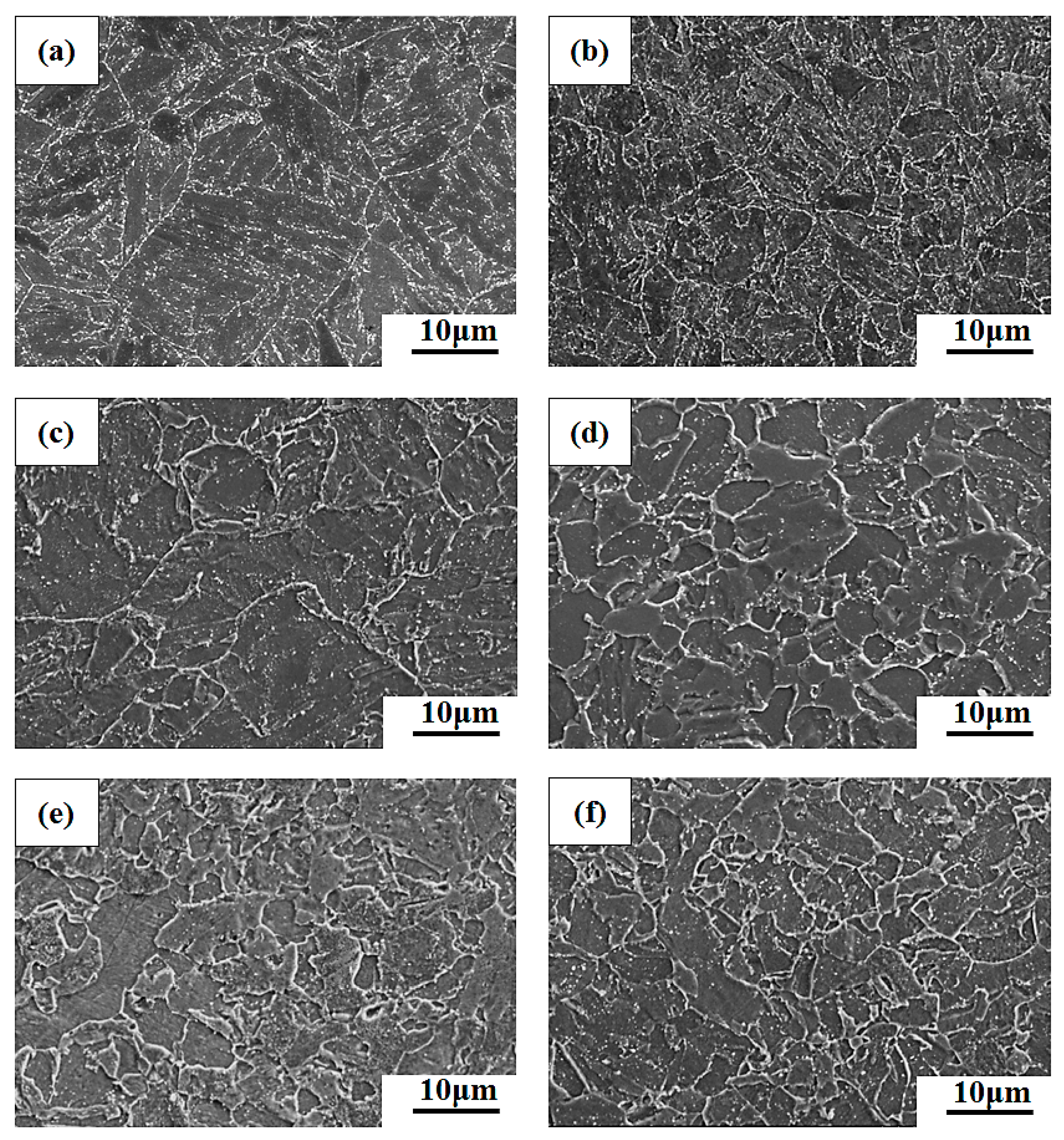
Figure 2 presents SEM micrographs showing the typical microstructures of various samples after tempering at 760 °C for 2 h. As shown in Figure 2a,b, the normalized and tempered microstructure of Gr.91 steel showed lath martensite packets and austenite boundaries decorated by M23C6 carbides. Stable fine MX carbides or carbonitrides were dispersed in the martensite matrix, which resisted coarsening at elevated temperature [23]. The prior austenite grain sizes (PAGSs) of the samples were determined by means of the line-intercept method and further confirmed by EBSD crystallographic analysis, as described in the following section. The PAGSs of the 940NT and 1060NT samples were about 7.4 and 17.0 µm, respectively. It has been reported that increasing the normalizing temperature from 1050 to 1150 °C also causes a decrease in M23C6 carbide size, which is associated with an increase in tensile strength but a reduction in ductility of P91 steel [6].
For the over-tempered specimens, it seemed that a decrease in carbide density and an increase in carbide size were observed (Figure 2c,d). The lath morphologies of the OT samples were also not as prominent as those of the NT ones. Moreover, the distribution of all precipitates was not uniform in the OT samples. A few areas in the OT samples lacked precipitates, which were more obvious in the 940NT-OT sample. As shown in Figure 2e,f, the grain structure of the PT samples was even more refined than those of the NT and OT samples. The lath morphology was obscure in two PT samples, especially in the 940NT-PT one. In previous work [8,9], the ICHAZ in the as-welded condition comprises of fine ferrite subgrains and fresh fine martensite, indicating a refined structure. Lath martensite in the PT samples was too fine to be revealed in the SEM observation. It was deduced that the coalescence of carbide-free lath martensite in the NT sample during the heating cycle contributed to the formation of ferrite subgrains in the PT specimen.
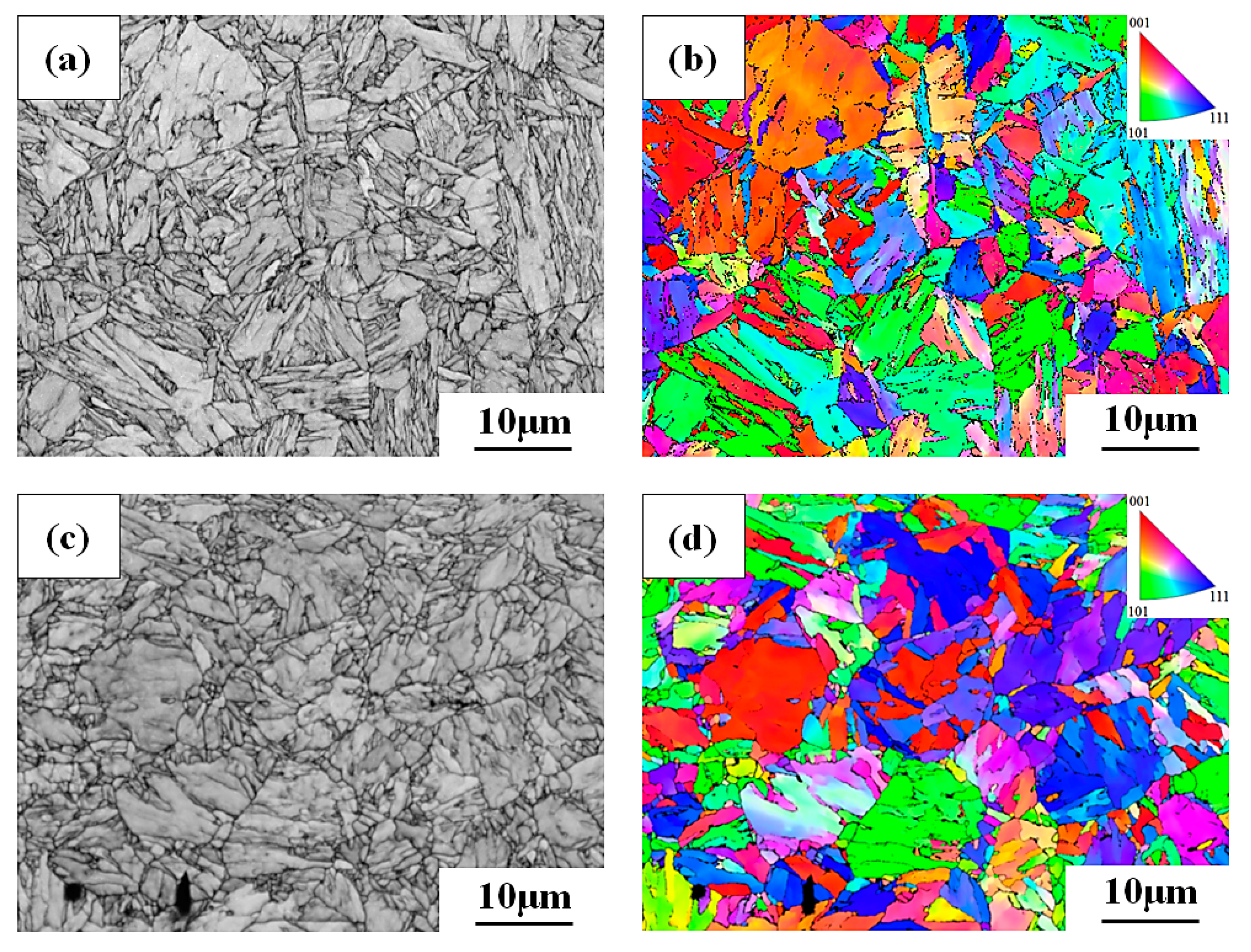
SEM micrographs and the inverse pole figures (IPFs) showing the individual grain orientation in different colors of 1060NT and 940NT are displayed in Figure 3. The great changes in color represent great differences in grain orientations. Within one grain, martensite packets oriented in nearly the same direction are of the same color, whereas different color zones are related to the lath martensite in different orientations. As shown in Figure 3a,b, the PAGSs and martensite packets of the 1060NT sample were obviously larger and coarser than those of the 940NT sample (Figure 3c,d). The coarser martensite packets in the 1060NT sample also made the lath structure much easier to be distinguished in this sample, in comparison with those in the 940-NT sample. In addition, the PAGSs of the 1060NT and 940NT samples were measured by EBSD maps to be about 7 and 17 µm, accordingly.
Figure 4a,b present the SEM micrograph and IPF map of the 1060NT-OT sample. The lath morphology was still distinguishable in the 1060NT-OT sample (Figure 4a). The PAGSs and martensite packet sizes of the 1060NT-OT sample were similar to those of the 1060NT sample. As indicated by the arrow in Figure 4a, a few fine grains were found in the 1060NT-OT sample. The IPF map (Figure 4b) showed that those fine grains indicated by the arrow had nearly the same orientation. It was expected that the short time of over-heating would cause disruption of the lath structure and enhance the polygonization process locally. An SEM micrograph and an IPF map of 1060NT-PT sample are shown in Figure 4c,d. The SEM micrograph (Figure 4c) revealed numerous fresh nucleated fine grains in the 1060NT-PT sample. The lath structure could hardly be observed in the 1060NT-PT sample, which was partially related to the extremely fine martensite [9]. The IPF map (Figure 4d) displayed some local areas, indicated by the arrow, which were oriented in almost the same direction but divided by sub-boundaries. Based on Figure 4d, the calculated PAGS of the 1060NT-PT sample was approximately 5.3 µm. The 940-OT sample also exhibited similar PAGS and microstructure of 940NT sample. Grain refinement was also observed in the 940NT-PT sample as illustrated in Figure 2f.
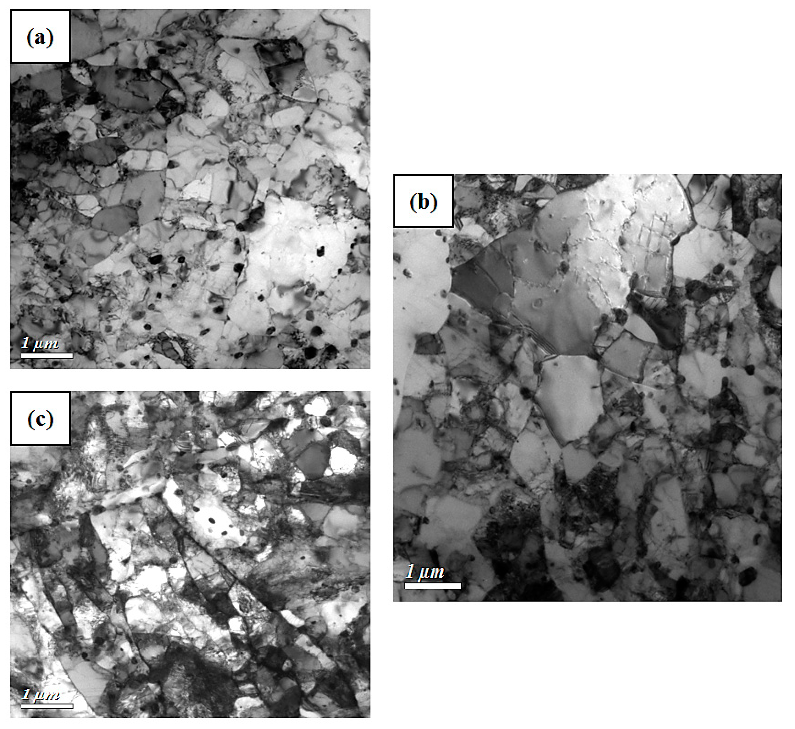
Figure 5 shows TEM micrographs of Gr.91 steel in the normalized and normalized-tempered conditions. In the normalized condition, lath martensite with a high dislocation density was observed (Figure 5a,b). Complete dissolution of Cr-rich carbides during normalization caused the prior austenite grain boundaries (PAGBs) of the two samples to be barely decorated by precipitates (Figure 5a,b). Normalizing at 940 °C assisted the formation of fine lath martensite therein (Figure 5b). After tempering, the detailed microstructures of the 1060NT and 940NT samples were similar (Figure 5c,d), consisting of lath martensite packets along with prior austenite grain boundaries decorated by precipitates. During tempering, the dislocation density was decreased and carbide precipitation was enhanced. The predominant precipitates formed in the NT specimens were M23C6 carbides, as confirmed by the diffraction pattern. A few fine MX precipitates, which could be carbides or carbonitrides (NbC, VC, and (NbV)(CN)), were dispersed in the martensite matrix [5]. Non-uniform carbide distributions were observed in the tempered martensite; some lath packages were free of precipitate along the lath boundaries. It is reported that increasing the normalizing temperature from 1050 to 1150 °C reduces the size of M23C6 carbides in P91 steel [6]. In this work, the carbide sizes in the two samples did not show significant differences between them. However, the lath width and packet size of the martensite in the 1060NT sample were larger than those in the 940NT sample.
TEM micrographs of the simulated microstructures after tempering are shown in Figure 6. Short-time over-tempering of tempered Gr.91 steel is expected to annihilate excess dislocations and cause carbide spheroidizing and coarsening [9]. The degraded lath structure and developed subgrains with low dislocation density in the over-tempered Gr.91 steel were responsible for the decrease in hardness, as compared with the NT substrates. It was seen that the parallel lath structure in the 1060NT sample was prone to be replaced by numerous cell structures or subgrains in the 1060NT-OT sample (Figure 6a). Similar morphologies were observed in the 940NT-OT sample (Figure 6b). It was observed that the carbide sizes seemed to be coarser in the 940NT-OT sample relative to those in the 1060NT-OT sample. The coexistence of fresh refined lath martensite with a high dislocation density and carbide-free ferrite subgrains caused incomplete hardening of the as-simulated PT or ICHAZ specimens [9]. In the as-simulated condition, most M23C6 carbides heated to slightly below the AC3 temperature dissolved into the matrix, and only few residual carbides remained [9]. After tempering, carbides precipitated mainly along lath boundaries and in ferrite subgrains. As shown in Figure 6c, tempered fine lath martensite was decorated by precipitates along the PAGBs and lath boundaries of the PT specimen. The fine laths in the PT sample were also comprised of many subgrains. A few coarse carbides in the PT specimen could be related to the growth of residual carbides during tempering of the Gr.91 steel. In addition, the aligned carbides in the 1060NT-PT specimens also showed the fact of migrated sub-boundaries after tempering.
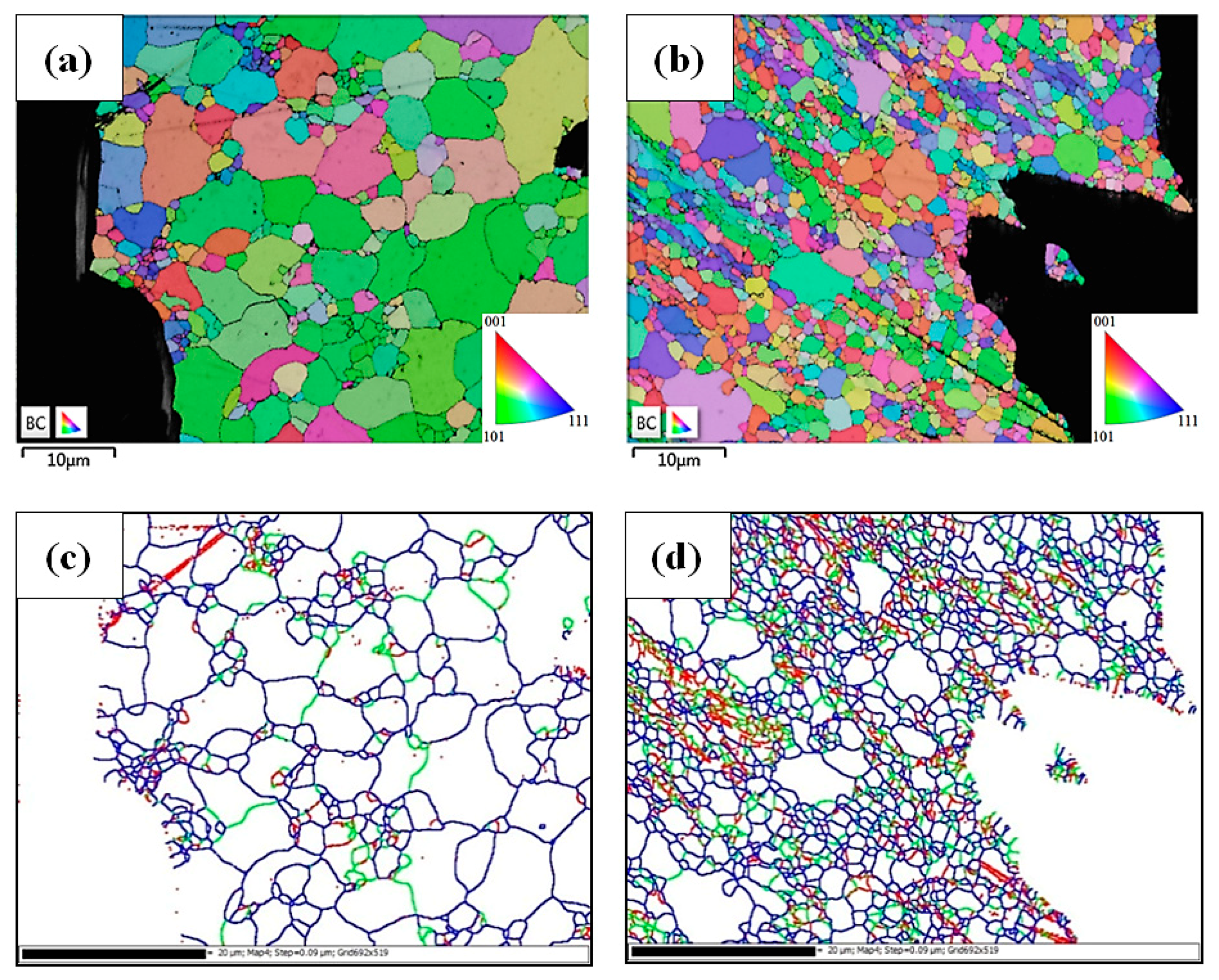
Figure 7 presents grain boundary crystallographic maps showing the detailed austenite grain boundaries and sub-boundaries, identified by measuring the misorientation between the adjacent grains. Subgrain boundaries include the lath and blocks/packets boundaries within the matrix. Prior austenite grain boundaries (PAGBs) are identified as high-angle grain boundaries with a misorientation above 15 degrees. Subgrain boundaries are indicated by red and green lines, whereas high-angle grain boundaries are indicated by blue lines. The grain boundary characteristics of the OT and PT samples normalized at different temperatures were evaluated. The high-angle grain boundaries delineated PAGB profiles of the 1060NT-OT sample (Figure 7a), which had the same grain boundary characteristics as the 1060NT sample. Subgrain boundaries (red and green) indicated the over-tempered martensite substructures. For the 1060NT-PT sample (Figure 7b), the grains profiled by high-angle grain boundaries were finer and more irregular than those of the 1060NT-OT sample (Figure 7a). Moreover, some fine grains (white zones in the figure), which were associated with the lack of subgrain boundaries inside, were deduced to be newly formed ferrite subgrains. It was seen that some long-island-like white zones were divided by subgrain boundaries in green lines in the 1060NT-PT sample, implying that those white zones could have been formed by excessive annihilation of dislocations and coalescence of martensite laths during infrared heating and tempering. Those white zones were expected to be the weak points in the samples.
Figure 7c,d display the grain boundary maps of the 940NT-OT and 940NT-PT samples. As compared with the counterpart samples normalized at 1060 °C, the 940NT-OT sample consisted of much finer austenite grain sizes. Similar to the 1060NT-PT sample, the 940NT-PT sample comprised of a fine-grained structure and a certain amount of white zones (Figure 7d). Those white zones obviously comprised of fewer subgrain boundaries. It was deduced that the fast coalescence of fine laths in the 940NT sample during infrared heating enhanced the formation of ferrite subgrains. The presence of fine ferrite subgrains, which were weak relative to the tempered lath martensites, was obviously harmful to the creep resistance of the PT samples. In addition, these fine laths in the 940NT sample were prone to combine and grow into ferrite subgrains during subsequent infrared heating and tempering.
Figure 8 shows the results of short-term creep tests for the specimens loaded under condition of 630 °C /120 MPa or 660 °C /80 MPa. Stress-rupture tests were terminated if the tested specimens did not rupture after 1000 h duration. The specimen elongation was also measured as an index of creep strength of the specimen at elevated temperature. The results indicated that the creep resistance of the samples normalized at 1060 °C was higher than the counterpart samples normalized at 940 °C, regardless of testing condition. Under the 630 °C /120 MPa condition, the stress-rupture life of the 1060NT sample (804 h) was much longer than that of the 940NT sample (244 h), as shown in Figure 8a. It was noticed that the stress-rupture lifetimes of the thermally treated samples were shorter than those of the NT samples in each group. The rupture life of the 1060NT-OT sample (256 h) was longer than that of the 940NT-OT sample (192 h). Among the tested samples in each group, the PT samples had the lowest resistance to creep rupture, especially the 940NT-PT sample. The 940NT-PT sample ruptured in a very short time (28 h) after applying stress. The high elongation of the PT samples before rupture indicated their inherent low strength. Figure 8b shows the creep samples tested under the condition of 660 °C/80 MPa. The PT samples also had a shorter time-to-rupture than did the NT and OT samples in each group. The OT samples were more likely to deform and rupture than were the NT samples. It was obvious that normalizing at higher temperature was helpful to improve the creep resistance of Gr.91 steel. By contrast, welding thermal cycles shortened the rupture time of the Gr.91 steel. Inevitably, the PTHAZ or ICHAZ in a Gr.91 steel weld was the zone most sensitive to creep rupture among the distinct zones in the weld.
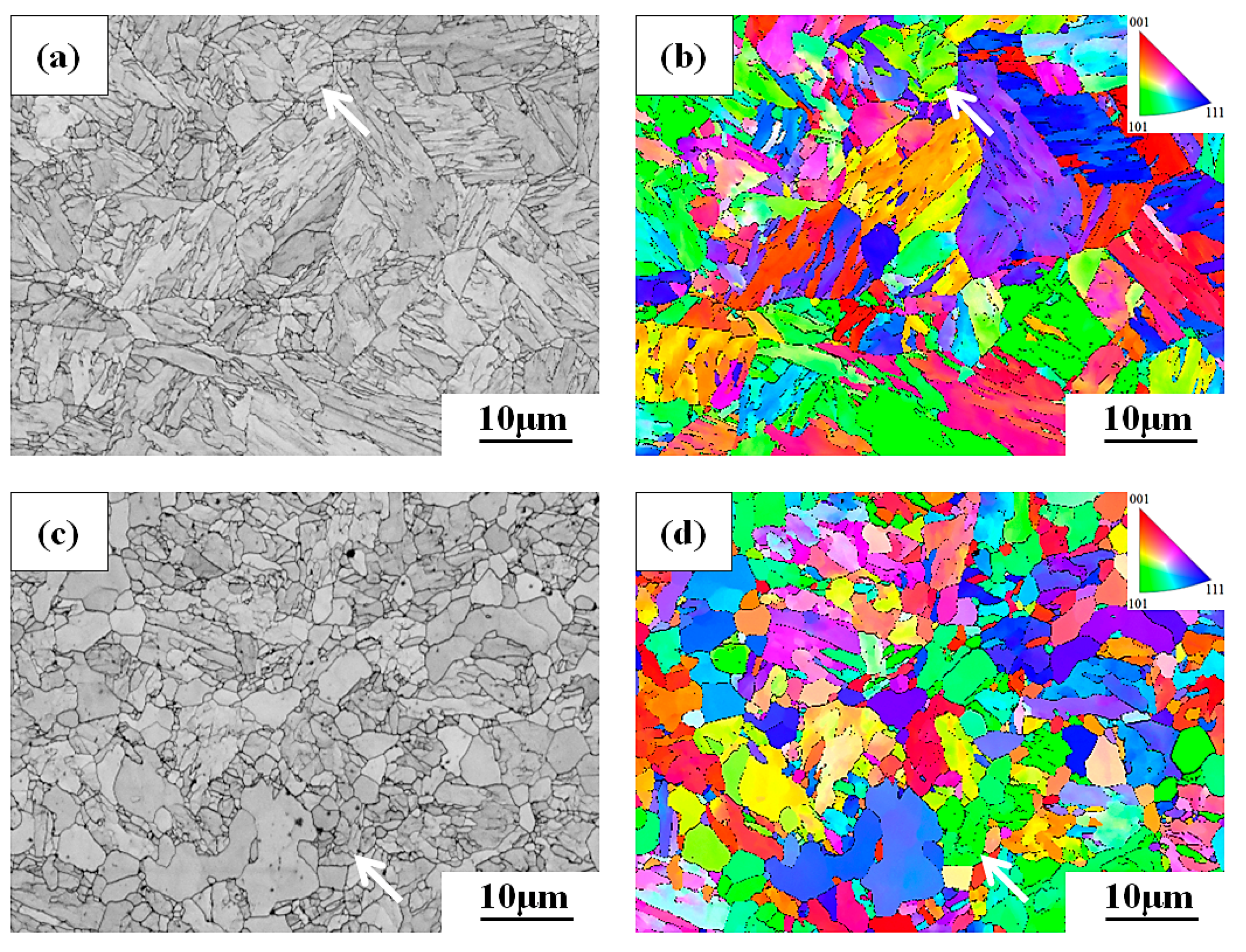
The SEM fractographs of all the samples after short-term creep tests showed ductile dimple fracture. The IPF maps and grain boundary maps next to the fractured zones in the ruptured samples are displayed in Figure 9. All the samples exhibited a fine-grained structure and texture under the 630 °C/120 MPa loading condition (Figure 9). The fracture life of OT samples was longer than that of the PT samples in each group, as displayed in Figure 8. During straining samples at elevated temperature, dynamic recrystallization resulted in the formation of refined grains (Figure 9a,b). Extensive nucleation of new grains occurred in the 1060NT-OT samples (Figure 9a), revealing that the original coarse grains were replaced by fine grains around the fractured zone in the 1060NT-OT sample. The corresponding grain boundary maps of the tested samples are shown in Figure 9c,d. It was observed that the low-angle grain boundaries (lath and packet boundaries) and PAGBs were less dense in the 940NT-PT sample (Figure 9d) than those in the 1060NT-OT one (Figure 9c). The time-to-fracture of the 940NT-PT sample was quite short (28 h). It was deduced that rapid combination and coalescence of refined substructures during straining at elevated temperature could explain the lower stress-rupture life of the PT samples at elevated temperature.
Figure 10 presents the IPF maps and grain boundary maps around the fractured zone, showing the distribution of grain size and grain boundary characteristics of the samples tested in the 660 °C/80 MPa condition. The PT samples had shorter fracture lifetimes than the OT ones (Figure 8), particularly the 940NT-PT sample (61h). As displayed in Figure 10a, grain growth after dynamic recrystallization occurred in the 940NT-PT sample. It was noticed that grain growth after recrystallization became much faster in the samples strained in the 660 °C/80 MPa condition. Similar results were reported that both sub grains and particle sizes increase during short term creep of Gr.91 steel [24]. The 1060NT-PT sample exhibited behaviors of variation in microstructures similar to those of the 940NT-PT one. By contrast, predominantly dynamic recrystallization still dominated the microstructural changes of the OT samples strained in the 660 °C/80 MPa condition (Figure 10b). Moreover, the grain boundary map of the 940NT-PT sample (Figure 10c) revealed a lack of substructures within the grain interior, which meant the great loss of strengthening substructures under the testing condition. By contrast, the 940NT-OT sample consisted of fine grains and a certain number of sub-boundaries (Figure 10d), as compared with the 940NT-PT sample (Figure 10c). It was also seen that the white grained zones were coarser relative to the neighboring grains, possibly due to the removal of the sub-structure during grain growth. Softening during creep could result from many causes, e.g., the growth of subgrains and the recovery of dislocations, coarsening of fine M23C6 carbides to hinder the growth of subgrains and boundary migrations. It was deduced that the fast coalescence of ferrite subgrains during straining at 660 °C assisted the formation of the coarse-grained structure of the PT samples. By contrast, the dynamic recrystallization retained the fine grains close to the fractured zone of the 940NT-OT and 1060NT-OT samples.
4. Discussion
Increasing the normalizing temperature from 940 to 1060 °C increased the martensite lath and packet sizes, as well as the PAGSs. The measured PAGSs of the 940NT and 1060NT samples were about 7.4 and 17.0 µm, respectively. The short-term over-tempering of the NT substrates had less effect on changing the PAGS but induced microstructural evolution. The TEM micrographs showed that the degraded lath structures and developed subgrains with low dislocation densities in the OT samples were associated with a decrease in hardness, as compared with the NT substrates. The tempered intercritical (IC) or partial transformation (PT) HAZ, which had been heated to below the AC3 temperature, exhibited refined grain sizes of less than 6.0 µm, regardless of the prior normalizing temperatures. The microstructures of PT samples comprised mainly of ferrite subgrains and refined tempered laths with carbides decorating the boundaries. It was expected that in the NT substrates, the original martensite packets with fewer carbides would assist the coalescence of fine laths into ferrite subgrains during infrared-heating and tempering. Similar results have indicated that preferential austenitization initiates from the prior austenite grain boundaries in the PTHAZ of Gr.91 steel welds during the heating cycle of welding [14]. The formation of subgrains in a lath with low Cr concentration in the tempered lath microstructure have a lower potential to transform to austenite during welding, thus, leading to the formation of over-tempered martensite [14]. On cooling, fine grains with large numbers of Cr-carbides are more likely to transform into fine laths or tiny packet-sized martensite with un-dissolved carbides [14]. Therefore, the mixed microstructures in the PT samples exhibited a fine-grained structure, as displayed in Figure 4 and Figure 7.
It is reported a finer PAGS, as in the fine-grained HAZ, leads to a higher rate of recovery of dislocations, higher coarsening rate of the subgrain structure and intergranular Cr-rich carbides, and consequently, to lower creep resistance [2]. The applied strain will enhance the growth of precipitates during creep of T91 steel [25]. In addition, preferential deformation of Cr-depleted grains accelerates grain boundary sliding and nucleation of creep cavities, which result in Type IV cracking [14,19]. In this work, the PT sample had the lowest rupture life among the tested samples in each group, regardless of the test condition. The rapid coalescence and growth of ferrite subgrains in the PT samples during straining at elevated temperature accounted for the deteriorated short-term creep resistance.
5. Conclusions
An infrared heating system was used to simulate the HAZ microstructures in Gr.91 steel welds, which included over-tempering (OT) and partial transformation (PT) zones. The short-term creep life of the simulated samples was determined under constant load at elevated temperature, and compared with the original substrates.
- (1)
- Increasing the normalizing temperature from 940 to 1060 °C improved the creep resistance of Gr.91 steel substrate, whereas the time-to-rupture of infrared-heated samples were shorter than those of the NT samples in each group. Among the tested samples in each group, the PT samples had the lowest resistance to creep rupture, especially the 940NT-PT sample.
- (2)
- Martensite packet sizes and PAGSs of the 1060NT sample were larger than those of the 940NT sample. The degraded lath structure and developed subgrains with low dislocation density in the over-tempered Gr.91 steel were responsible for a decrease in hardness, as compared with that of the NT substrates. Overall, the PAGSs and martensite packet sizes of the OT sample were similar to those of the NT substrate in each group; by contrast, refined grains were found in the PT samples. The microstructures of the PT samples comprised of fine lath martensite, ferrite subgrains, and carbides decorated the grain and sub-grain boundaries.
- (3)
- Excessive dislocation recovery, rapid coalescence of refined martensite laths and growth of ferrite subgrains were responsible for the deteriorated creep resistance of the PT samples as compared with other samples.
Author Contributions
L.-W.T. designed and planned the experiment. R.-K.S. assisted EBSD and microstructural characteristics evaluation. H.-W.W. and T.-J.W. carried out the experimental tests. All authors were involved in completing the manuscript.
Funding
This research was funded by the Ministry of Science and Technology, ROC, grant number MOST 106-2221-E-019 -060 -MY3, and the APC was funded by National Taiwan Ocean University.
Conflicts of Interest
The authors declare no conflict of interest.
References
- Fujio, A.B. Creep behavior, deformation mechanisms, and creep life of modified 9Cr-1Mo steel. Metall. Mater. Trans. A 2015, 46, 5610–5625. [Google Scholar]
- El-Azim, M.E.; Ibrahim, O.H.; El-Desoky, O.E. Long term creep behaviour of welded joints of P91 steel at 650 °C. Mater. Sci. Eng. A 2013, 560, 678–684. [Google Scholar] [CrossRef]
- Viswanathan, R.; Bakker, W. Materials for ultrasupercritical coal power plants- boiler materials: Part 1. J. Mater. Eng. Perform. 2001, 10, 81–95. [Google Scholar] [CrossRef]
- Viswanathan, R.; Bakker, W. Materials for ultrasupercritical coal power plants- turbine materials: Part II. J. Mater. Eng. Perform. 2001, 10, 96–101. [Google Scholar] [CrossRef]
- Shrestha, T.; Alsagabi, S.F.; Charit, I.; Potirniche, G.P.; Glazoff, M.V. Effect of heat treatment on microstructure and hardness of Grade 91 steel. Metals 2015, 5, 131–149. [Google Scholar] [CrossRef]
- Das, C.R.; Albert, S.K.; Swaminathan, J.; Raju, S.; Bhaduri, A.K.; Murty, B.S. Transition of crack from type IV to Type II resulting from improved utilization of boron in the modified 9Cr-1Mo steel weldment. Metall. Mater. Trans. A 2012, 43, 3724–3741. [Google Scholar] [CrossRef]
- Saini, N.; Pandey, C.; Mahapatra, M.M. Effect of normalizing temperature on fracture characteristic of tensile and impact tested creep strength-enhanced ferritic P92 steel. J. Mater. Eng. Perform. 2017, 26, 5414–5424. [Google Scholar] [CrossRef]
- Xu, X.; West, G.D.; Siefert, J.A.; Parker, J.D.; Thomson, R.C. Microstructural characterization of the heat-affected zones in Grade 92 steel welds: double-pass and multipass welds. Metall. Mater. Trans. A 2018, 49, 1211–1230. [Google Scholar] [CrossRef]
- Hsiao, T.H.; Chen, T.C.; Jeng, S.L.; Chung, T.J.; Tsay, L.W. Effects of simulated microstructure on the creep rupture of the modified 9Cr-1Mo steel. J. Mater. Eng. Perform. 2016, 25, 4317–4325. [Google Scholar] [CrossRef]
- Abson, D.J.; Rothwell, J.S. Review of type IV cracking of weldments in 9–12%Cr creep strength enhanced ferritic steels. Int. Mater. Rev. 2013, 58, 437–473. [Google Scholar] [CrossRef]
- Hongo, H.; Tabuchi, M.; Watanabe, T. Type IV creep damage behavior in Gr. 91 steel welded joints. Metall. Mater. Trans. A 2012, 43, 1163–1173. [Google Scholar] [CrossRef]
- Divya, M.; Das, C.R.; Albert, S.K.; Goyal, S.; Ganesh, P.; Kaul, R.; Bhaduri, A.K. Influence of welding process on Type IV cracking behavior of P91 steel. Mater. Sci. Eng. A 2014, 613, 148–158. [Google Scholar] [CrossRef]
- Laha, K.; Chandravathi, K.S.; Parameswaran, P.; Rao, K.B.S. Type IV cracking susceptibility in weld joints of different grades of Cr-Mo ferritic steel. Metall. Mater. Trans. A 2009, 40, 386–397. [Google Scholar] [CrossRef]
- Wang, Y.; Kannan, R.; Li, L. Correlation between intercritical heat-affected zone and type IV creep damage zone in Grade 91 steel. Metall. Mater. Trans. A 2018, 49, 1264–1275. [Google Scholar] [CrossRef]
- Spigarelli, S.; Quadrini, E. Analysis of the creep behaviour of modified P91 (9Cr–1Mo–NbV)welds. Mater. Des. 2002, 23, 547–552. [Google Scholar] [CrossRef]
- Yatomi, M.; Yoshida, K.; Kimura, T. Difference of creep crack growth behaviour for base, heat-affected zone and welds of modified 9Cr–1Mo steel. Mater. High Temp. 2011, 28, 109–113. [Google Scholar] [CrossRef]
- Kumar, Y.; Venugopal, S.; Sasikala, G.; Albert, S.K.; Bhaduri, A.K. Study of creep crack growth in a modified 9Cr–1Mo steel weld metal and heat affected zone. Mater. Sci. Eng. A 2016, 655, 300–309. [Google Scholar] [CrossRef]
- Yu, X.; Babu, S.S.; Terasaki, H.; Komizo, Y.; Yamamoto, Y.; Santella, M.L. Correlation of precipitate stability to increased creep resistance of Cr–Mo steel welds. Acta Mater. 2013, 61, 2194–2206. [Google Scholar] [CrossRef]
- Wang, Y.; Kannan, R.; Li, L. Identification and characterization of intercritical heat-affected zone in as-welded Grade 91 weldment. Metall. Mater. Trans. A 2016, 47, 5680–5684. [Google Scholar] [CrossRef]
- Peng, Y.Q.; Chen, T.C.; Chung, T.J.; Jeng, S.L.; Huang, R.T.; Tsay, L.W. Creep rupture of the simulated HAZ of T92 steel compared to that of a T91 steel. Materials 2017, 10, 139. [Google Scholar] [CrossRef]
- Gauss, C.; Souza Filho, I.R.; Sandim, M.J.R.; Suzuki, P.A.; Ramirez, A.J.; Sandim, H.R.Z. In situ synchrotron X-ray evaluation of strain-induced martensite in AISI 201 austenitic stainless steel during tensile testing. Mater. Sci. Eng. A 2016, 651, 507–516. [Google Scholar] [CrossRef]
- Escobar, J.D.; Faria, G.A.; Wu, L.; Oliveira, J.P.; Mei, P.R.; Ramirez, A.J. Austenite reversion kinetics and stability during tempering of a Ti-stabilized supermartensitic stainless steel: Correlative in situ synchrotron x-ray diffraction and dilatometry. Acta Mater. 2017, 138, 92–99. [Google Scholar] [CrossRef]
- Pandey, C.; Giri, A.; Mahapatra, M.M. Effect of normalizing temperature on microstructural stability and mechanical properties of creep strength enhanced ferritic P91 steel. Mater. Sci. Eng. A 2016, 657, 173–184. [Google Scholar] [CrossRef]
- Cerri, E.; Evangelista, E.; Spigarelli, S.; Bianchi, P. Evolution of microstructure in a modified 9Cr–1Mo steel during short term creep. Mater. Sci. Eng. A 1998, 245, 285–292. [Google Scholar] [CrossRef]
- Nakajima, T.; Spigarelli, S.; Evangelista, E.; Endo, T. Strain Enhanced Growth of Precipitates during Creep of T91. Mater. Trans. 2003, 44, 1802–1808. [Google Scholar] [CrossRef] [Green Version]
Figure 1.
Schematic diagrams showing (a) tested samples cut from the Gr.91 steel tube, (b) the specimen dimensions for creep test, (c) the fractured zone cut from crept sample for EBSD analysis.
Figure 1.
Schematic diagrams showing (a) tested samples cut from the Gr.91 steel tube, (b) the specimen dimensions for creep test, (c) the fractured zone cut from crept sample for EBSD analysis.

Figure 2.
Scanning electron microscope (SEM) micrographs of the (a) 1060NT, (b) 940NT, (c) 1060NT-OT, (d) 940NT-OT, (e) 1060NT-PT, and (f) 940NT-PT samples.
Figure 2.
Scanning electron microscope (SEM) micrographs of the (a) 1060NT, (b) 940NT, (c) 1060NT-OT, (d) 940NT-OT, (e) 1060NT-PT, and (f) 940NT-PT samples.

Figure 3.
(a) SEM micrographs and (b) inverse pole figure (IPF) map of the 1060NT sample; (c) SEM micrograph and (d) IPF map of the 940NT sample.
Figure 3.
(a) SEM micrographs and (b) inverse pole figure (IPF) map of the 1060NT sample; (c) SEM micrograph and (d) IPF map of the 940NT sample.

Figure 4.
(a) SEM micrographs and (b) IPF map of the 1060NT-OT sample; (c) SEM micrographs and (d) IPF map of the 1060NT-PT sample.
Figure 4.
(a) SEM micrographs and (b) IPF map of the 1060NT-OT sample; (c) SEM micrographs and (d) IPF map of the 1060NT-PT sample.

Figure 5.
Transmission electron microscope (TEM) micrographs of the (a) 1060N, (b) 940N, (c) 1060NT, and (d) 940NT samples.
Figure 5.
Transmission electron microscope (TEM) micrographs of the (a) 1060N, (b) 940N, (c) 1060NT, and (d) 940NT samples.

Figure 6.
TEM micrographs of the (a) 1060NT-OT, (b) 940NT-OT and (c) 1060NT-PT samples.

Figure 7.
Grain boundary maps of the (a) 1060NT-OT, (b) 1060NT-PT, (c) 940NT-OT and (d) 940NT-PT samples. ![Metals 08 01072 i001]() :1°~5°,
:1°~5°, ![Metals 08 01072 i002]() :5°~15°,
:5°~15°, ![Metals 08 01072 i003]() :15°~62.5°.
:15°~62.5°.
 :1°~5°,
  :5°~15°,
  :15°~62.5°.
Figure 7.
Grain boundary maps of the (a) 1060NT-OT, (b) 1060NT-PT, (c) 940NT-OT and (d) 940NT-PT samples. ![Metals 08 01072 i001]() :1°~5°,
:1°~5°, ![Metals 08 01072 i002]() :5°~15°,
:5°~15°, ![Metals 08 01072 i003]() :15°~62.5°.
:15°~62.5°.
:1°~5°, :5°~15°, :15°~62.5°.
Figure 8.
The short-term creep tests of various samples at (a) 630 °C/120 MPa, (b) 660 °C/80 MPa.

Figure 9.
IPF maps of the (a) 1060NT-OT, (b) 940NT-PT samples; grain boundary maps of the (c) 1060NT-OT, (d) 940NT-PT samples strained at 630 °C/120 MPa. ![Metals 08 01072 i004]() :1°~5°,
:1°~5°, ![Metals 08 01072 i005]() :5°~15°,
:5°~15°, ![Metals 08 01072 i006]() :15°~62.5°.
:15°~62.5°.
 :1°~5°,
  :5°~15°,
  :15°~62.5°.
Figure 9.
IPF maps of the (a) 1060NT-OT, (b) 940NT-PT samples; grain boundary maps of the (c) 1060NT-OT, (d) 940NT-PT samples strained at 630 °C/120 MPa. ![Metals 08 01072 i004]() :1°~5°,
:1°~5°, ![Metals 08 01072 i005]() :5°~15°,
:5°~15°, ![Metals 08 01072 i006]() :15°~62.5°.
:15°~62.5°.
:1°~5°, :5°~15°, :15°~62.5°.
Figure 10.
IPF crystallographic maps of the (a) 940NT-PT, (b) 940NT-OT samples; grain boundary crystallographic maps of the (c) 940NT-PT, (d) 940NT-OT samples strained at 660 °C /80 MPa. ![Metals 08 01072 i007]() :1°~5°,
:1°~5°, ![Metals 08 01072 i008]() :5°~15°,
:5°~15°, ![Metals 08 01072 i009]() :15°~62.5°.
:15°~62.5°.
 :1°~5°,
  :5°~15°,
  :15°~62.5°.
Figure 10.
IPF crystallographic maps of the (a) 940NT-PT, (b) 940NT-OT samples; grain boundary crystallographic maps of the (c) 940NT-PT, (d) 940NT-OT samples strained at 660 °C /80 MPa. ![Metals 08 01072 i007]() :1°~5°,
:1°~5°, ![Metals 08 01072 i008]() :5°~15°,
:5°~15°, ![Metals 08 01072 i009]() :15°~62.5°.
:15°~62.5°.
:1°~5°, :5°~15°, :15°~62.5°.
© 2018 by the authors. Licensee MDPI, Basel, Switzerland. This article is an open access article distributed under the terms and conditions of the Creative Commons Attribution (CC BY) license (http://creativecommons.org/licenses/by/4.0/).
Share and Cite
MDPI and ACS Style
Wu, H.-W.; Wu, T.-J.; Shiue, R.-K.; Tsay, L.-W. The Effect of Normalizing Temperature on the Short-Term Creep Rupture of the Simulated HAZ in Gr.91 Steel Welds. Metals 2018, 8, 1072. https://doi.org/10.3390/met8121072
AMA Style
Wu H-W, Wu T-J, Shiue R-K, Tsay L-W. The Effect of Normalizing Temperature on the Short-Term Creep Rupture of the Simulated HAZ in Gr.91 Steel Welds. Metals. 2018; 8(12):1072. https://doi.org/10.3390/met8121072
Chicago/Turabian StyleWu, Hao-Wei, Tai-Jung Wu, Ren-Kae Shiue, and Leu-Wen Tsay. 2018. "The Effect of Normalizing Temperature on the Short-Term Creep Rupture of the Simulated HAZ in Gr.91 Steel Welds" Metals 8, no. 12: 1072. https://doi.org/10.3390/met8121072
Note that from the first issue of 2016, this journal uses article numbers instead of page numbers. See further details here.