Microstructure and Anisotropy of Plastic Properties of Thermomechanically-Processed HSLA-Type Steel Plates


Institute of Engineering Materials and Biomaterials, Silesian University of Technology, 18a Konarskiego Street, Gliwice 44-100, Poland
*
Author to whom correspondence should be addressed.
Metals 2018, 8(5), 304; https://doi.org/10.3390/met8050304
Submission received: 8 April 2018
/
Revised: 20 April 2018
/
Accepted: 25 April 2018
/
Published: 28 April 2018
(This article belongs to the Special Issue Researches and Simulations in Steel Rolling)
Abstract
:The paper presents the investigation results of the impact of shear bands on microstructure, mechanical properties, and anisotropy of plastic properties of HSLA (high-strength, low-alloy) type steel plates, produced in the process of thermomechanical rolling. A lack of conditions ensuring the complete static recrystallization between successive roll passes leads to localization of plastic deformation and formation of shear bands in dynamically-recrystallized austenite enriched with carbon and other interstitial elements, which transform into carbide segregation bands during tempering. These bands are the cause of low impact resistance of rolled plates, especially in the transverse direction, and the high degree of anisotropy of plastic properties in the plates.
1. Introduction
High-strength steel plates with guaranteed toughness are the basic material for building heavily-loaded structures and installations, especially wheel cranes, road machines, overhead travelling cranes, and heavy transportation vehicles. These applications require a high ratio of strength to weight. They are constructed of quenched and tempered plates with guaranteed ductility, amenable to cold and hot formability, weldability, and limited anisotropy of plastic properties [1,2,3,4]. To meet these competing performance requirements, the selection of chemical composition is critical to ensure the required hardenability and weldability of steel and high mechanical properties of plates [5,6,7,8].
The HSLA steels with microadditions meet the performance requirements in a wide range of mechanical and technological properties [9,10,11]. Introduction of B in the amount of ≤0.005% increases hardenability. The addition of ≤0.04% Ti, ≤0.04% Nb, and ≤0.08% V forms the MX type (M-Nb, Ti; X-N, C) interstitial phases that enable production of products with fine-grained microstructure, while reducing the concentration of C ≤ 0.17%, Cr ≤ 0.8%, and Mo ≤ 0.5%. Hence, toughened steel plates with YS (yield stress) from 700 to 1100 MPa and KV−40°C (impact energy at −40 °C) of ≥ 40 J can be produced. These additions also decrease the temperature of the initial heating of plates prior to welding to ≤150 °C [12,13,14].
Particularly useful technology for steel plate fabrication is an energy-saving thermomechanical process, consisting of rolling in a temperature range adjusted to the kinetics of precipitation of MX type phases in austenite and complete recrystallization of the γ phase in the intervals between successive roll passes. The plates are quenched immediately after isothermal holding at the temperature of rolling finish for the time necessary to form 50% fraction of statically-recrystallized austenite (t0.5) [15,16,17]. A lack of complete recrystallization of austenite deformed between roll passes causes an accumulation of strain in subsequent passes and an increase of plastic deformation heterogeneity, leading to the formation of shear bands in the austenite in the direction of rolling [18,19,20]. These bands may cause the anisotropy of plastic properties in the plates and decrease their impact toughness [21,22,23].
2. Materials and Methods
The tests were carried out on low-carbon toughened steel. The chemical composition is shown in Table 1. The requirements for weldable plates are: YS > 960 MPa and a ductile-brittle transition temperature T45J equal to −40 °C. The carbon equivalent of this steel, calculated on its chemical composition, is equal to CE = 0.55. The steel is characterized by high metallurgical cleanliness, associated with low content of P and S.
The conditions for thermomechanical processing of plates were determined based on the examination of plastic deformation of samples subjected to torsion at deformation rates of 1, 3, and 10 s−1, in a temperature range from 900 to 1100 °C. The tests were conducted on a 7M type SETARAM (Setaram, Caluire-et-Cuire, France) torsional plastometer. Samples were 6 mm in diameter and 10 mm in gauge length. The specimens were mounted in the jaws of the plastometer, covered with a quartz tube (in an argon atmosphere). The samples were induction heated for 2 min up to an austenitizing temperature of 1150 °C, and after being held at this temperature for 10 min, were allowed to cool to the test temperature.
In order to determine the recrystallization kinetics of plastically-deformed austenite, double-hit torsion tests to a given strain (ε = 0.2) at a rate of 3 s−1, in a temperature range from 900 to 1100 °C. This temperature range covers a typical plate hot-rolling schedule. The samples were isothermally held between successive deformations for a period of 0.2 s to 120 s. Evaluation of the fraction of recrystallized austenite was done on the basis of the softening degree of austenite [24,25].
Rolling of flat samples with a starting thickness of 40 mm and a width of 40 mm to a 15 mm thick plate was carried out on a duo-reversing mill with a roll diameter of 500 mm and a peripheral speed of 0.65 m/s. The samples were soaked for 60 min at 1150 °C and then rolled during five roll passes in a temperature range from 1100 °C to 900 °C, with a deformation rate of 3 s−1. Rolling was performed in two variants, in accordance with the scheme presented in Figure 1.
The first variant (Figure 1a) consisted of using normal cooling conditions in the intervals between successive roll passes, determined by normal processing temperature changes, whereas in the second variant (Figure 1b) retention shields of heat-resistant steel were used to reduce the rate of temperature drop of the rolled strip in the intervals between successive passes. The final holding of the rolled sections for time t0.5 at a rolling finish temperature of 900 °C were realized in a retention casing lined with an insulating material. Sections of plates, produced in both variants of the rolling process, referred to as thermomechanical processing (TMP), were tempered for 60 min at temperatures of 550 °C, 600 °C, and 650 °C, followed by air cooling.
Observations of the microstructure of thin foils and the identification of phases extracted from replicas were done in a JEOL JEM—200 CX (Jeol, Tokyo, Japan) transmission electron microscope, at an accelerating voltage equal to 200 kV. Discs Ø 3 mm in diameter were ground using an abrasive paper to the thickness of about 0.3 mm, and then electrolytically polished using a TenuPol-5 (Struers, Ballerup, Denmark) device. To investigate the effect of the conditions of thermomechanical processing and tempering temperature on mechanical properties, static tensile test and impact test at −40 °C were conducted. Three samples from the plates produced at each of the processing variants for tensile tests were taken at both the longitudinal and transverse direction. Charpy V samples taken at both directions were examined. The standard deviation and variance are given for six measurements.
3. Results and Discussion
3.1. Plastometric Behavior
Continuous torsion tests of samples performed at a rate of 1, 3 ,and 10 s−1 allowed the determination of the effect of the temperature in a range from 1100 to 900 °C on the value of εm strain (i.e., a strain corresponding to the maximum value of yield stress) (Table 2). This information was used to estimate strain necessary to initiate dynamic recrystallization of austenite. The data given in Table 2 show that the value of εm strain (estimated based on continuous torsion tests) increases with a decrease in the test temperature and an increase of the deformation rate.
The study has shown that hot deformation of steel is controlled by the dynamic recovery process and that recovery and static recrystallization of plastically-deformed austenite take place in the intervals between successive deformation stages. It follows from the course of the softening kinetics (corresponds to a volume fraction recrystallized) of austenite (Figure 2) that the time of complete recrystallization of the γ phase of HSLA steel at 1100 °C is 50 s and increases to about 400 s at 900 °C. Similarly, in the temperature range from 1100 °C to 900 °C the time t0.5—half-time recrystallization of austenite—increases from 9 to 60 s. Such relatively long complete recrystallization times tR and half-time t0.5 of austenite cause difficulties in the rolling process due to the relatively high cooling rate of the strip in air between successive roll passes.
Knowledge of tR and t0.5 times is necessary to specify the steel plates’ rolling process with complete recrystallization of austenite in the intervals between successive roll passes and the formation of at least 50% fraction of recrystallized austenite after plastic working, prior to their quenching from the rolling finish temperature.
3.2. Microstructure of Thermomechanically-Processed Plates
Analysis revealed significant differences in microstructure and mechanical properties of the plates produced in both variants of thermomechanical treatment, both in the condition as hardened from rolling finish temperature and after tempering in a temperature range from 550 to 650 °C.
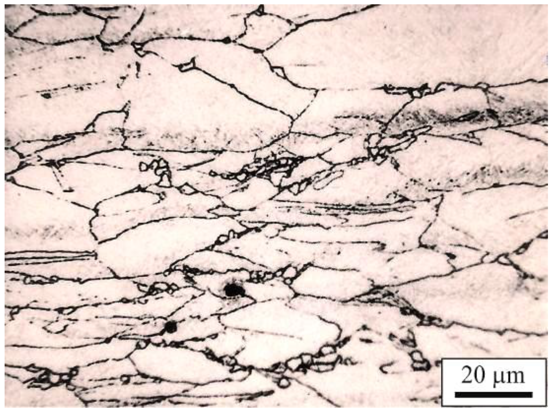
The presence of segregation bands, propagating in the direction of rolling (Figure 3), were revealed in plates produced according to the first variant of thermomechanical treatment (I TMP). The plates were open-air cooled in the intervals between successive roll passes and held for 60 s following the plastic deformation finish (prior to quenching). In this case, the interval times, especially between final roll passes, were clearly shorter than the tR time of the full recrystallization of austenite, and even shorter than the t0.5 time. Detailed analysis showed that shear bands spread without changing the orientation when crossing grain boundaries (Figure 4), and martensite formed in these areas is characterized by a higher microhardness (845 HV0.03) compared to the surrounding matrix (486 HV0.03).
This indicates that shear bands are formed as a result of heterogeneous deformation due to short duration intervals between rolling passes and only partial recrystallization of austenite. Similar effects of inhomogeneous deformation in a form of segregation bands in structural steels have been studied in [26,27,28,29,30]. For example Rui et al. [26] revealed segregation bands in HSLA-type constructional steel, containing 0.16% C, 1.50% Mn, and microadditions of Nb, Ti, and V with concentrations of 0.035%, 0.015%, and 0.004%, respectively, hot-rolled in a temperature range from 1120 to 850 °C. Recently, Fuping et al. [27] investigated the mechanisms of formation and development of these bands in 0.2C–5Mn medium-Mn steel. The effects of inhomogeneous deformation were also revealed in non-ferrous alloys and in pure metals. Korbel et al. [31,32,33] found them in Al-Mg alloys, subjected to high cold plastic deformation, whereas Richert and Korbel [34] observed them in highly-deformed aluminium Al99.992.
Shear bands did not vanish after tempering of the samples cut from sections of plates produced in I variant TMP, i.e., direct quenching from the rolling finish temperature after being held in air for 60 s prior to quenching (Figure 5). After tempering in the temperature range of 550 °C to 650 °C the steel shows a microstructure of tempered martensite with dispersive precipitates of carbides of larger size at the boundaries of austenite grains.
An investigation of the microstructure of thin foils in transmission electron microscope images revealed that there was strong fragmentation of prior austenite grains within the shear bands, associated with the dynamic recrystallization. There is evidence of intensive dynamic recovery with the formation of a continuous carbide halo on their boundaries. The dynamic recrystallization in these bands was also confirmed by Tóth et al., in C22 unalloyed toughened steel grade [35], by Wang et al., in AISI 201 steel grade [28], and by Meyers et al., in 18-8-type steel [36].
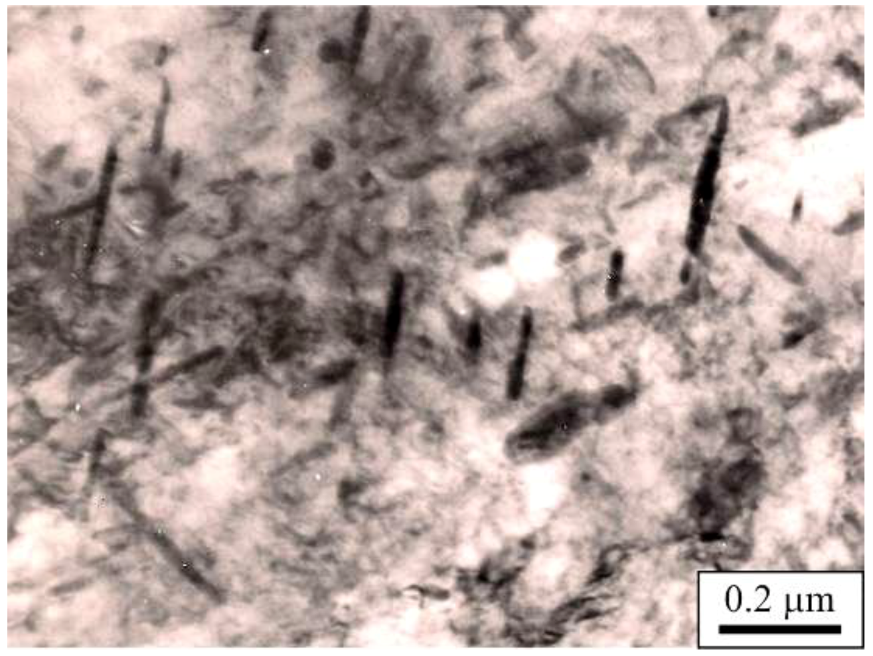
Narrow areas of lath martensite with different orientations to the steel matrix (Figure 6) are present in irregular areas of the shear bands. The laths contained dispersive MC carbides with a lamellar morphology with a continuous halo of M23C6 carbides on grain boundaries of dynamically-recrystallized austenite (Figure 7). The elongated form of MC carbides indicates the anisotropic process of their coagulation in the stress field. The presence of high concentrations of dispersive carbides explains the reason for strong carbon segregation in shear bands. The presence of M23C6-type dispersive carbides (Figure 8) was also revealed with the carbon replica method. Precipitation of these carbides is favoured by the decreasing solubility of alloying elements in austenite along with a decrease in temperature [37], which was the case during holding of rolled sections in air before hardening.
Increasing the time of intervals between successive passes through the use of a retention cover allows for isothermal holding of the rolled plate section prior to hardening for time t0.5, according to the second variant of thermomechanical treatment (II TMP). This contributed to the improvement of the chemical composition homogeneity and formation of a more fine-grained microstructure. Steel plate sections, 15 mm thick, produced under these conditions, after an isothermal hold at a temperature of 900 °C for t0.5 = 60 s prior to water quenching had a microstructure of partially-recrystallized austenite. It consisted of elongated and pancaked statically-recovered grains and fine recrystallized grains with traces of broadened segregation bands (Figure 9). Very fine recrystallized grains are distributed mainly on grain boundaries and on the contact of statically-recovered grains, due to the highest strain concentration in those areas during hot-working [37]. Some portion of the recrystallized austenite (indicated by the arrows) is also visible inside the grains (Figure 9 and Figure 10). This indicates that they could form in deformation bands [12,20]. The partially-recrystallized microstructure distinctly appears in the transverse microsections (Figure 10), whereby the portion of recrystallized austenite fractions with a grain size of approx. 4 μm is approximately 15%.
A similar distribution of recrystallized austenite grains was disclosed in longitudinal microsections (Figure 11). Elongated dynamically-recovered prior austenite grains with fuzzy shear bands are also visible (Figure 12). These are typical pancake microstructures formed under hot-working conditions corresponding to completing rolling below a non-recrystallization austenite temperature [22,24]. Increasing the fraction of recrystallized austenite to 50% is possible by using the retention cover that maintains the tR condition between final roll passes and a constant temperature of rolled strip before hardening in the temperature of the rolling finish for time t0.5.
Microstructure observations of thin foils, prepared from the plate section produced according to the second variant, revealed laths of different widths and orientations in martensite packets. Some of the martensite laths showed evidence of fragmentation (Figure 13) caused by the impact of subgrain boundaries. There was a considerable crystallographic misorientation angle on their growth—formed in statically-recovered austenite. The other laths revealed curvilinear grain boundaries and variable widths (Figure 14).
Steels tempered in the range of 550 °C to 650 °C have a fairly diverse microstructure. Specimens cut from plates hardened after rolling or after holding in air and tempered at 550 °C obtain microstructures of tempered martensite with granular and lamellar Fe3C particles distributed inside the grains and at the boundaries of laths, as well as in sub-boundaries of statically-recovered ferrite. Increasing the tempering temperature causes coagulation of cementite, especially in the areas of shear bands.
Specimens obtained from a plate section produced according to the II TMP have a similar microstructure in the tempered state. In this case, in the microstructure of the steel tempered at the temperature of 550 °C, there are thin lamellar precipitates of Fe3C on lath boundaries. There is the recovered ferrite with dispersive lamellar particles of the phase with preferred orientations with matrix inside the laths (Figure 15). Lamellar precipitates transform into granular Fe3C particles, distributed on lath boundaries and in subgrain boundaries of the recovered ferrite with an increase in the tempering temperature (Figure 16).
3.3. Results of Mechanical Properties
The diversified microstructure of steel has an impact on the mechanical properties of plates produced in both variants of thermomechanical treatment, successively subjected to tempering in a temperature range from 550 °C to 650 °C. This concerns the UTS (Ultimate Tensile Strength) strength, YS0.2 yield stress, TEl (total elongation), and RA (reduction in area), determined by tensile tests at room temperature, and Charpy V samples tested at −40 °C (KV−40°C). It is especially true for the anisotropy of plastic properties of plates as determined by the ratio of the energy of cracking transverse and longitudinal samples. Detailed results from the tensile tests are listed in Table 3. The mean values of three measurements with the standard deviation are given. The detailed impact toughness results with statistical information are summarized in Table 4.
Experimental results revealed that the plate section, obtained in the first variant of thermomechanical treatment with direct hardening after rolling finish at 900 °C and tempering at 550 °C had a YS0.2 equal to about 1020 MPa, a UTS of about 1100 MPa, a TEI of around 19%, and KV−40°C impact energy of 43 J (Figure 17). The ratio of energy to break Charpy V transverse samples and longitudinal samples in a tempering temperature range from 550 °C to 650 °C varies from 0.65 to 0.74.
Hardening of plate sections, after holding in air for 60 s after completing rolling at the temperature of 900 °C, does not cause significant changes in mechanical properties of the steel due to a limited progress of static recrystallization. Sections of the plate produced under these conditions show comparable mechanical properties after tempering in the same temperature range. The static recovery is not able to remove a significant amount of dislocations. This is why the segregation processes of carbon and the resultant carbide precipitation during tempering take place. Finally, the mechanical properties are similar to the I TMP.
Samples produced in the II TMP using a retention cover have a superior set of mechanical properties in the tempered state. The II TMP limits the possibility of forming shear bands due to reduced strain accumulation in the final roll passes. Advanced recovery and the partial recrystallization of deformed austenite resulted in comparable mechanical properties to the I TMP but the plates had over twice the higher crack toughness and significantly lower anisotropy of plastic properties. The energy of breaking Charpy V longitudinal samples taken from section of steel plate tempered at 550 °C, is equal to about 74 J. Tempering at 650 °C increased the energy to about 156 J (Figure 17d). However, the energy of breaking Charpy V samples transverse to the direction of rolling, in the same range of tempering, varies from 61 J to 129 J. Thus, the aspect ratio of transverse to longitudinal samples is equal to about 0.82.
To summarize, the microstructure has a limited effect on strength properties and total elongation. However, the impact toughness is more sensitive to microstructure changes, such as a structural notch or shear bands. The tendency for shear bands and subsequent carbide formation is smaller. Moreover, the significant number of dislocations is removed. Hence, the segregation processes and a driving force for carbide formation are diminished. The microstructural products formed from a mixture of recrystallized and recovered grains are less sensitive to dynamic loading conditions. That is why the stress concentrations decrease and the impact toughness of the samples produced in the II TMP is twice as high.
4. Conclusions
Experiments revealed that a lack of complete recrystallization of austenite between subsequent roll passes leads to the localization of plastic deformation and the formation of segregation bands enriched with carbon and other alloying elements in austenite. High concentrations of dispersive MC-type carbides can be observed inside laths of martensite located in the area of these bands and a continuous halo of M23C6 carbides on their boundaries. Segregation bands formed during hot-working do not vanish during isothermal holding of plates at the temperature of the rolling finish for 60 s. Tempering of the steel also does not eliminate the shear bands and carbide precipitates present inside martensite laths lead to a decrease in crack resistance, especially in the direction transverse to the rolling direction and the occurrence of strong anisotropy of plastic properties of the plates.
The use of a retention cover allows for almost complete recrystallization of austenite in the intervals between initial passes. The isothermal holding of the rolled strip prior to quenching for the time t0.5 prevents the formation of segregation bands and ensures a superior set of mechanical properties in the tempered state, and particularly high crack resistance and low anisotropy of plastic properties. The improved impact toughness behaviour is due to the smaller driving force for carbide formation in the samples produced under conditions of decreased strain localization, which contain a mixture of recrystallized and recovered grains. The plates produced under isothermal holding conditions and tempered in a range from 550 to 650 °C have: YS0.2 above 1000 MPa, UTS ~1100 MPa, and an impact toughness at −40 °C up to 150 J.
Author Contributions
M.O. conceived, designed, and performed the experiments and wrote the paper; A.G. performed the light microscopy tests and analyzed the data; and all authors discussed and reviewed the paper.
Acknowledgments
This work was financially supported with statutory funds of Faculty of Mechanical Engineering of Silesian University of Technology in 2018.
Conflicts of Interest
The authors declare no conflict of interest.
References
- Shen, X.J.; Tang, S.; Chen, J.; Liu, Z.Y. Grain refinement in surface layers though deformation-induced ferrite transformation in microalloyed steel plate. Mater. Des. 2017, 113, 137–141. [Google Scholar] [CrossRef]
- Hu, J.; Du, L.; Xie, H.; Gao, X.; Misra, R.D.K. Microstructure and mechanical properties of TMCP heavy plate microalloyed steel. Mater. Sci. Eng. A 2014, 607, 122–131. [Google Scholar] [CrossRef]
- Żuk, M.; Górka, J.; Czupryński, A.; Adamiak, M. Properties and structure of the weld joints of quench and tempered 4330V steel. Metalurgija 2016, 55, 613–616. [Google Scholar]
- Kurc-Lisiecka, A.; Piwnik, J.; Lisiecki, A. Laser welding of new grade of advanced high strength steel STRENX 1100 MC. Arch. Metall. Mater. 2017, 62, 1651–1657. [Google Scholar] [CrossRef]
- Grajcar, A.; Lesz, S. Influence of Nb microaddition on a microstructure of low-alloyed steels with increased manganese content. Mater. Sci. Forum 2012, 706–709, 2124–2129. [Google Scholar] [CrossRef]
- Radwański, K. Structural characterization of low-carbon multiphase steels merging advanced research methods with light optical microscopy. Arch. Civ. Mech. Eng. 2016, 16, 282–293. [Google Scholar] [CrossRef]
- Hwan, B.; Lee, C.G. Influence of thermomechanical processing and heat treatments on tensile and Charpy impact properties of B and Cu bearing high-strength low-alloy steel. Mater. Sci. Eng. A 2010, 527, 4341–4346. [Google Scholar] [CrossRef]
- Kurc-Lisiecka, A.; Lisiecki, A. Laser welding of the new grade of advanced high-strength steel DOMEX 960. Mater. Tehnol. 2017, 51, 199–204. [Google Scholar] [CrossRef]
- Liu, Y.; Shi, L.; Liu, C.; Yu, L. Effect of step quenching on microstructure and mechanical properties of HSLA steel. Mater. Sci. Eng. A 2016, 675, 371–378. [Google Scholar] [CrossRef]
- Górka, J. Welding thermal cycle-triggered precipitation processes in steel S700MC subjected to the thermo-mechanical control processing. Arch. Metall. Mater. 2017, 62, 331–336. [Google Scholar] [CrossRef]
- Bakshi, S.; Jared, N.; Sasidhar, K.N.; Dhande, T.; Sharma, V. Effect of microstructure and crystallographic texture on mechanical anisotropy of Ti-Nb microalloyed hot rolled 800MPa HSLA steel. Mater. Charact. 2018, 136, 346–357. [Google Scholar] [CrossRef]
- Park, D.; Huh, M.; Shim, J.; Jung, W. Strengthening mechanism of hot rolled Ti and Nb microalloyed HSLA steels containing Mo and W with various coiling temperature. Mater. Sci. Eng. A 2013, 560, 528–534. [Google Scholar] [CrossRef]
- Illescas, S.; Fernández, J.; Guilemany, J.M. Kinetics analysis of the austenitic grain growth in HSLA steel with a low carbon content. Mater. Lett. 2008, 62, 3478–3480. [Google Scholar] [CrossRef]
- Larzabal, G.; Isasti, N.; Rodriguez-Ibabe, J.M.; Uranga, P. Evaluating strengthening and impact toughness mechanism for ferritic and bainitic microstructures in Nb, Nb-Mo and Ti-Mo microalloyed steels. Metals 2017, 7, 65. [Google Scholar] [CrossRef]
- Opiela, M.; Grajcar, A. Hot deformation behavior and softening kinetics of Ti-V-B microalloyed steels. Arch. Civ. Mech. Eng. 2012, 3, 327–333. [Google Scholar] [CrossRef]
- Opiela, M. Effect of thermomechanical processing of the microstructure and mechanical properties of Nb-Ti-V microalloyed steel. J. Mater. Eng. Perform. 2014, 9, 3379–3388. [Google Scholar] [CrossRef]
- Grajcar, A.; Radwański, K. Microstructural comparison of the thermomechanically treated and cold deformed Nb-microalloyed TRIP steel. Mater. Tehnol. 2014, 48, 679–683. [Google Scholar]
- Li, X.; Wu, P.; Yang, R.; Zhao, S.; Wang, X. Nb segregation at prior austenite grain boundaries and defects in high strength low alloy steel during cooling. Mater. Des. 2017, 115, 165–169. [Google Scholar] [CrossRef]
- Peng, Z.; Li, L.; Gao, J.; Xuo, X. Precipitation strengthening of titanium microalloyed high-strength steel plates with isothermal treatment. Mater. Sci. Eng. A 2016, 657, 413–421. [Google Scholar] [CrossRef]
- Karmakar, A.; Biswas, S.; Mukherjee, S.; Chakrabarti, D. Effect of composition and thermo-mechanical processing schedule on the microstructure, precipitation and strengthening of Nb-microalloyed steel. Mater. Sci. Eng. A 2017, 690, 158–169. [Google Scholar] [CrossRef]
- Hu, J.; Du, L.; Wang, J.; Xie, H.; Misra, R.D.K. Structure-mechanical property relationship in low carbon microalloyed steel plate processed using controlled rolling and two-stage continuous cooling. Mater. Sci. Eng. A 2013, 585, 197–204. [Google Scholar] [CrossRef]
- Sanz, L.; Pereda, B.; López, B. Effect of thermomechanical treatment and coiling temperature on the strengthening mechanism of low carbon steels microalloyed with Nb. Mater. Sci. Eng. A 2017, 685, 377–390. [Google Scholar] [CrossRef]
- Zrnik, J.; Kvackaj, T.; Pongpaybul, A.; Sricharoenchai, P. Effect of thermomechanical processing on the microstructure and mechanical properties of Nb-Ti microalloyed steel. Mater. Sci. Eng. A 2001, 319, 321–325. [Google Scholar] [CrossRef]
- Gómez, M.; Rancel, L.; Medina, S.F. Assessment of austenite static recrystallization and grain size evolution during multipass hot rolling of a niobium-microalloyed steel. Met. Mater. Int. 2009, 15, 689–699. [Google Scholar] [CrossRef] [Green Version]
- Ren, A.; Ji, Y.; Zhou, G.; Yuan, Z.; Han, B.; Li, Y. Hot deformation behaviour of V-microalloyed steel. J. Iron Steel Res. Int. 2010, 17, 55–60. [Google Scholar] [CrossRef]
- Rui, F.; Shengli, L.; Xinde, Z.; Qing, A. Microstructural characterization and formation mechanism of abnormal segregation band of hot rolled ferrite/pearlite steel. J. Alloy. Comp. 2015, 646, 787–793. [Google Scholar]
- Yuan, F.; Bian, X.; Jiang, P.; Yang, M.; Wu, X. Dynamic shear response and evolution mechanism of adiabatic shear band in a ultrafine-grained austenite-ferrite duplex steel. Mech. Mater. 2015, 89, 47–58. [Google Scholar] [CrossRef]
- Wang, B.; Liu, Z.; Zhao, S.; Sun, J. Microstructural evolution in adiabatic shear band in the ultrafine-grained austenitic stainless steel processed by multi-axial compression. Mater. Sci. Eng. A 2014, 611, 100–107. [Google Scholar] [CrossRef]
- Jonas, J.J. Effect of shear band formation on texture development in warm-rolled IF steels. J. Mater. Process. Tech. 2001, 117, 293–299. [Google Scholar] [CrossRef]
- Odeshi, A.G.; Bassim, M.N.; Al-Amerri, S. Effect of heat treatment on adiabatic shear bands in a high-strength low alloy steel. Mater. Sci. Eng. A 2006, 419, 69–75. [Google Scholar] [CrossRef]
- Korbel, A.; Raghunathan, V.S.; Teirlineck, D.; Spitzig, W.; Richmond, O.; Embry, J.D. A structural study of the influence of pressure on shear band formation. Acta Metall. 1984, 32, 511–519. [Google Scholar] [CrossRef]
- Korbel, A.; Richert, M. Formation of shear bands during cyclic deformation of aluminium. Acta Metall. 1985, 33, 1971–1978. [Google Scholar] [CrossRef]
- Korbel, A.; Embry, J.D.; Hatherly, M.; Martin, P.L.; Erbsloh, H.W. Microstructural aspects of strain localization in Al-Mg alloys. Acta Metall. 1986, 34, 1999–2009. [Google Scholar] [CrossRef]
- Richert, M.; Korbel, A. The effect of strain localization on mechanical properties of Al99,992 in the range of large deformations. J. Mater. Process. Tech. 1995, 53, 331–340. [Google Scholar] [CrossRef]
- Toth, L.S.; Hildebrand, A.; Molinari, A. Dynamic recrystallization in adiabatic shear bands. J. Phys. 2000, 10, 365–370. [Google Scholar]
- Meyers, M.A.; Xu, Y.B.; Xue, Q.; Perez-Prado, M.T.; McNelley, T.R. Microstructural evolution in adiabatic shear localization in stainlles steel. Acta Metall. 2003, 51, 1307–1325. [Google Scholar]
- Adamczyk, J.; Opiela, M. Influence of the thermo-mechanical treatment parameters on the inhomogeneity of the austenite structure and mechanical properties of the Cr-Mo steel with Nb, Ti, and B microadditions. J. Mater. Process. Tech. 2004, 157–158, 456–461. [Google Scholar] [CrossRef]
Figure 1.
Schematic of thermomechanical processing (TMP) according to the I non-isothermal variant TMP (a) and the II isothermal variant TMP (b).
Figure 1.
Schematic of thermomechanical processing (TMP) according to the I non-isothermal variant TMP (a) and the II isothermal variant TMP (b).

Figure 2.
Effect of the test temperature on the softening fraction of plastically deformed austenite (X denotes a softening fraction).
Figure 2.
Effect of the test temperature on the softening fraction of plastically deformed austenite (X denotes a softening fraction).

Figure 3.
Lath martensite with distinct shear bands; I TMP.

Figure 4.
Shear band in the prior austenite; I TMP.

Figure 5.
Tempered martensite with the remaining shear bands; I TMP; tempering temperature 550 °C.

Figure 6.
Lath martensite in dynamically-recovered austenite and elongated martensite laths within dynamically-recrystallized austenite; I TMP.
Figure 6.
Lath martensite in dynamically-recovered austenite and elongated martensite laths within dynamically-recrystallized austenite; I TMP.

Figure 7.
Dispersive MC carbides within a martensite lath in dynamically-recrystallized austenite with a continuous M23C6 carbide halo on the grain boundaries; I TMP.
Figure 7.
Dispersive MC carbides within a martensite lath in dynamically-recrystallized austenite with a continuous M23C6 carbide halo on the grain boundaries; I TMP.

Figure 8.
Extracted M23C6 particle; I TMP.

Figure 9.
Pancaked prior austenite grains with traces of fuzzy shear bands and fine recrystallized grains (indicated by the arrows); II TMP; cross-section.
Figure 9.
Pancaked prior austenite grains with traces of fuzzy shear bands and fine recrystallized grains (indicated by the arrows); II TMP; cross-section.

Figure 10.
Fine recrystallized prior austenite grains located along grain boundaries and inside (indicated by the arrows) the austenite grains; II TMP; cross-section.
Figure 10.
Fine recrystallized prior austenite grains located along grain boundaries and inside (indicated by the arrows) the austenite grains; II TMP; cross-section.

Figure 11.
A mixture of pancaked and recrystallized prior austenite grains; II TMP; longitudinal section.
Figure 11.
A mixture of pancaked and recrystallized prior austenite grains; II TMP; longitudinal section.

Figure 12.
Elongated dynamically-recovered prior austenite grains with fuzzy shear bands; II TMP; longitudinal section.
Figure 12.
Elongated dynamically-recovered prior austenite grains with fuzzy shear bands; II TMP; longitudinal section.

Figure 13.
Martensite laths with dispersive Fe3C particles and retained austenite films between the laths; II TMP.
Figure 13.
Martensite laths with dispersive Fe3C particles and retained austenite films between the laths; II TMP.

Figure 14.
Curved boundaries of martensite laths with dispersive Fe3C particles and retained austenite films; II TMP.
Figure 14.
Curved boundaries of martensite laths with dispersive Fe3C particles and retained austenite films; II TMP.

Figure 15.
Dispersive plate particles of Fe3C; II TMP; tempering temperature 550 °C.

Figure 16.
Granular and partially-elongated particles of Fe3C in the recovered ferrite; II TMP; tempering temperature 650 °C.
Figure 16.
Granular and partially-elongated particles of Fe3C in the recovered ferrite; II TMP; tempering temperature 650 °C.

Figure 17.
Effects of the TMP variant and tempering temperature on YS0.2 (a); UTS (b); TEl (c) and impact toughness (Charpy V samples) (d).
Figure 17.
Effects of the TMP variant and tempering temperature on YS0.2 (a); UTS (b); TEl (c) and impact toughness (Charpy V samples) (d).


Table 1.
Chemical composition of the investigated HSLA-type steel (wt. %).
| C % | Mn % | Si % | Cr % | Mo % | Ti % | Nb % | V % | B % | P % | S % |
|---|---|---|---|---|---|---|---|---|---|---|
| 0.17 | 1.37 | 0.26 | 0.24 | 0.48 | 0.004 | 0.025 | 0.019 | 0.002 | 0.012 | 0.001 |
Table 2.
Results of continuous torsion tests.
| No. | Deformation Temperature, °C | Strain Rate, s−1 | Rotational Speed of the Movable Sample Holder, rpm | Strain Corresponding to Maximum Stress, εm | Maximum Stress, σm, MPa |
|---|---|---|---|---|---|
| 1 | 900 | 1 | 55 | 0.65 | 189 |
| 2 | 950 | 1 | 55 | 0.45 | 177 |
| 3 | 1000 | 1 | 55 | 0.40 | 140 |
| 4 | 1050 | 1 | 55 | 0.31 | 126 |
| 5 | 1100 | 1 | 55 | 0.20 | 109 |
| 6 | 900 | 3 | 166 | 0.68 | 213 |
| 7 | 950 | 3 | 166 | 0.47 | 180 |
| 8 | 1000 | 3 | 166 | 0.43 | 160 |
| 9 | 1050 | 3 | 166 | 0.35 | 140 |
| 10 | 1100 | 3 | 166 | 0.21 | 118 |
| 11 | 900 | 10 | 551 | 0.82 | 229 |
| 12 | 950 | 10 | 551 | 0.58 | 207 |
| 13 | 1000 | 10 | 551 | 0.50 | 178 |
| 14 | 1050 | 10 | 551 | 0.43 | 162 |
| 15 | 1100 | 10 | 551 | 0.35 | 149 |
Table 3.
The effect of TMP conditions and tempering temperature on the mechanical properties.
| TMP Conditions | Tempering Temperature | Test Direction | YS0.2*, MPa | UTS*, MPa | TEl*, % | RA*, % | YS0.2/UTS |
|---|---|---|---|---|---|---|---|
| I variant TMP 900 °C/water | 550 °C | LD | 1021 ± 15 | 1103 ± 19 | 16.2 ± 1.2 | 66.3 ± 2.8 | 0.93 |
| TD | 1074 ± 17 | 1127 ± 22 | 17.4 ± 0.8 | 60.7 ± 2.0 | 0.95 | ||
| 600 °C | LD | 1018 ± 12 | 1081 ± 15 | 17.8 ± 1.0 | 68.6 ± 3.5 | 0.94 | |
| TD | 1036 ± 11 | 1099 ± 18 | 18.0 ± 2.1 | 65.8 ± 4.8 | 0.94 | ||
| 650 °C | LD | 1010 ± 18 | 1060 ± 16 | 19.2 ± 1.4 | 69.9 ± 2.9 | 0.95 | |
| TD | 1021 ± 15 | 1069 ± 23 | 18.5 ± 1.0 | 67.4 ± 3.8 | 0.96 | ||
| I variant TMP 900 °C/60 s/water | 550 °C | LD | 1038 ± 21 | 1097 ± 21 | 17.0 ± 0.4 | 66.4 ± 3.3 | 0.95 |
| TD | 1089 ± 13 | 1116 ± 15 | 17.3 ± 0.9 | 62.3 ± 2.5 | 0.98 | ||
| 600 °C | LD | 1010 ± 16 | 1078 ± 17 | 18.4 ± 1.4 | 66.3 ± 4.5 | 0.94 | |
| TD | 1060 ± 15 | 1080 ± 22 | 18.3 ± 1.5 | 66.9 ± 5.0 | 0.98 | ||
| 650 °C | LD | 1005 ± 13 | 1049 ± 19 | 18.9 ± 1.2 | 68.5 ± 2.9 | 0.96 | |
| TD | 1038 ± 19 | 1045 ± 11 | 18.6 ± 1.6 | 67.0 ± 3.5 | 0.99 | ||
| II variant TMP 900 °C/60 s/water | 550 °C | LD | 1036 ± 14 | 1095 ± 17 | 18.9 ± 0.5 | 64.1 ± 4.2 | 0.95 |
| TD | 1042 ± 15 | 1112 ± 15 | 17.2 ± 1.0 | 63.0 ± 2.0 | 0.94 | ||
| 600 °C | LD | 1021 ± 17 | 1074 ± 23 | 19.9 ± 0.7 | 66.5 ± 3.1 | 0.95 | |
| TD | 1025 ± 11 | 1080 ± 25 | 17.8 ± 2.2 | 64.2 ± 3.8 | 0.95 | ||
| 650 °C | LD | 1000 ± 15 | 1029 ± 24 | 22.0 ± 1.8 | 67.3 ± 2.5 | 0.97 | |
| TD | 1005 ± 19 | 1036 ± 20 | 18.4 ± 1.6 | 66.9 ± 3.2 | 0.97 |
* The average value calculated from three measurements; LD—longitudinal direction, TD—transverse direction.
Table 4.
The effect of TMP conditions and tempering temperature on the impact energy of Charpy V samples.
Table 4.
The effect of TMP conditions and tempering temperature on the impact energy of Charpy V samples.
| TMP Conditions | Tempering Temperature | Test Direction | KV−40 °C *, J | KVTD/KVLD | Standard Deviation for α = 0.05 | Variance |
|---|---|---|---|---|---|---|
| I variant TMP 900 °C/water | 550 °C | LD | 38.2 ± 7.8 | 0.65 | 3.05 | 9.35 |
| TD | 24.9 ± 5.9 | 1.64 | 2.69 | |||
| 600 °C | LD | 40.9 ± 11.8 | 0.63 | 3.60 | 12.98 | |
| TD | 26.0 ± 9.8 | 3.06 | 9.37 | |||
| 650 °C | LD | 42.8 ± 9.5 | 0.74 | 3.18 | 10.12 | |
| TD | 32.0 ± 6.3 | 2.45 | 6.04 | |||
| I variant TMP 900 °C/60 s/water | 550 °C | LD | 35.9 ± 11.8 | 0.70 | 3.94 | 15.59 |
| TD | 25.0 ± 21.6 | 6.91 | 47.87 | |||
| 600 °C | LD | 42.9 ± 19.5 | 0.74 | 6.12 | 37.56 | |
| TD | 26.8 ± 15.7 | 6.85 | 47.05 | |||
| 650 °C | LD | 45.3 ± 10.7 | 0.60 | 4.07 | 16.58 | |
| TD | 32.8 ± 10.4 | 3.36 | 11.30 | |||
| II variant TMP 900 °C/60 s/water | 550 °C | LD | 73.5 ± 9.4 | 0.84 | 3.71 | 13.83 |
| TD | 61.4 ± 17.7 | 7.27 | 52.87 | |||
| 600 °C | LD | 103.0 ± 14.7 | 0.87 | 5.39 | 29.08 | |
| TD | 89.9 ± 9.5 | 3.45 | 11.95 | |||
| 650 °C | LD | 156.4 ± 17.7 | 0.82 | 7.27 | 52.87 | |
| TD | 128.9 ± 15.3 | 6.26 | 39.31 |
* The average value calculated from six measurements; LD—longitudinal direction, TD—transverse direction.
© 2018 by the authors. Licensee MDPI, Basel, Switzerland. This article is an open access article distributed under the terms and conditions of the Creative Commons Attribution (CC BY) license (http://creativecommons.org/licenses/by/4.0/).
Share and Cite
MDPI and ACS Style
Opiela, M.; Grajcar, A. Microstructure and Anisotropy of Plastic Properties of Thermomechanically-Processed HSLA-Type Steel Plates. Metals 2018, 8, 304. https://doi.org/10.3390/met8050304
AMA Style
Opiela M, Grajcar A. Microstructure and Anisotropy of Plastic Properties of Thermomechanically-Processed HSLA-Type Steel Plates. Metals. 2018; 8(5):304. https://doi.org/10.3390/met8050304
Chicago/Turabian StyleOpiela, Marek, and Adam Grajcar. 2018. "Microstructure and Anisotropy of Plastic Properties of Thermomechanically-Processed HSLA-Type Steel Plates" Metals 8, no. 5: 304. https://doi.org/10.3390/met8050304
Note that from the first issue of 2016, this journal uses article numbers instead of page numbers. See further details here.