1. Introduction
The demand for plate steels having increased combinations of strength, toughness, and weldability for linepipe applications continues to rise. In the past several decades, multiple efforts have been made to meet these needs through alloying and thermo-mechanical control processing (TMCP) with accelerated cooling. These processes result in complex microstructures, mainly consisting of low temperature transformation products such as bainite and acicular ferrite [
1].
It is well known that upper and lower bainite are representative terms to describe bainite microstructures, depending on transformation temperature and carbide distribution. However, there are additional terms frequently used for bainite microstructures. Bhadeshia [
2] summarized the terms such as granular bainite, inverse bainite, columnar bainite, pearlitic bainite, and grain boundary lower bainite, etc. Except for granular bainite, the different bainite descriptions are not used systematically and their mechanisms of formation are not well understood. This situation reflects the complex character of bainitic microstructures in particular for the TMCP processed steels. Controlling these complex microstructures aims to achieve high strength without significant loss of toughness or weldability of the linepipe steels.
The American Petroleum Institute (API) provides a series of product specification levels [
3] for pipes to transport various hydrocarbon products (high pressure gas and liquid) fabricated from these advanced plate steels. For example, grade API-5L X65 is specified to have a minimum yield strength (YS) of 448 MPa (65 ksi) and a minimum ultimate tensile strength (UTS) of 531 MPa (77 ksi). However, there are complications in precisely defining the mechanical properties of
pipe specimens, due to the through-thickness variation in bending strains during pipe forming. This is further complicated by a requirement for properties to be realized in the end-use product and not the originating plate properties.
Mechanical properties of steel pipes are generally examined in both the longitudinal direction (LD) and the transverse direction (TD) because of their anisotropic characteristics. Ju et al. [
4] reported the anisotropic fracture toughness of an X65 steel pipe having ferrite and pearlite microstructures by crack tip opening displacement (CTOD) tests. Their results show that the room temperature fracture toughness measured with crack propagation along the LD is about one half of the value as with propagation in the TD. Mechanical anisotropy is also observed in the plate before pipe forming. Venkatsurya et al. [
5] reported YS, UTS and fracture toughness values for X70 and X80 plate steels as a function of the test axis rotation from the plate LD. While the polygonal ferrite and acicular ferrite microstructures in the two steels exhibit almost identical morphologies in the different directions, the YS and the impact toughness values were strongly dependent on the specimen orientation. Mechanical property anisotropy in linepipe steel plates commonly arises due to chemical segregation (non-uniform distribution of inclusions and a banded microstructure with elongated grains) and a non-random crystallographic texture resulting from TMCP [
6].
In addition to the plate microstructure, the strain gradient related to the pipe manufacturing process contributed to anisotropic mechanical properties of the pipe. Sohn et al. [
7] compared mechanical properties in both X70 and X80 steels before and after spiral pipe forming at different through-thickness positions. Both steels exhibited increased hardness due to pipe forming at every sample position. In contrast, the yield strength measured nearest the inner diameter (ID) of the pipe was less than the parent plate yield strength. This variation of YS values through the thickness direction was explained based on the Bauschinger effect and work hardening related to the pre-strain imposed by the pipe forming process.
The effect of pre-strain on the mechanical properties of a variety of linepipe steels has been documented in a number of studies [
8,
9,
10,
11,
12]. Sivaprasad et al. [
8] applied tensile pre-strains ranging from 1% to 5% to Cu-strengthened X80 and X100 steel plates along the LD. Pre-strains above 2% increased the YS and deteriorated both the fracture toughness and the uniform elongation (UE). Fukuda et al. [
9] used four different double-submerged arc welded (DSAW) pipes made from X60, X65, and two X80 steels for testing with both compressive and tensile pre-strains. The tensile pre-strain gradually increased the YS values, while the YS decreased more substantially during a compressive pre-strain of 1% and approached a constant value at compressive pre-strains of 3% or larger. Shinohara et al. [
10] investigated anisotropic tensile property evolution for an X100 linepipe steel plate with TD tensile pre-strains. Tensile tests were performed along the LD, TD, and diagonal direction (DD). While there were gradual increases in YS and UTS for the three directions with increasing pre-strain, the UE in the TD was close to zero after a 4% pre-strain.
These prior studies identify the importance of pre-strain on the evolution of mechanical properties related to pipe forming. It should also be noted that pipe forming generates an inhomogeneous distribution of pre-strain, resulting in tensile property gradients through the thickness direction, and these gradients are important to understand. Full-thickness mechanical tests are industrially preferred to measure the nominal mechanical properties of actual pipes. Such tests often require flattening of the pipe sections and ignore through-thickness variations, which are the focus of this study. Analogous to pipe forming, pipe flattening creates inhomogeneous pre-strain in the test specimens extracted from the pipe, and the flattening process will influence the mechanical properties obtained from the test specimen. In the current study, a distinctive pipe flattening process using a four-point bending apparatus was designed to minimize strain localization, and applied to two X65 pipe specimens having either a bainitic or a ferrite/pearlite microstructure. Tensile tests on specimens from the flattened pipe sections were performed and the results were compared to the as-received tensile properties.
2. Materials and Methods
Two sections of commercially produced UOE pipes (X65 grade) were obtained. They are designated “steel B” having a bainitic microstructure and “steel FP” with a ferrite/pearlite microstructure.
Table 1 gives the chemical compositions of the two steels. These compositions are similar. The as-received pipe section of steel B had a thickness of 19.1 mm and an outer diameter of 559 mm, whereas the pipe section of steel FP had a thickness of 15.9 mm and an outer diameter of 508 mm. Both the rolling direction of the plate before pipe forming and the welding line are parallel to the longitudinal axis of the pipe.
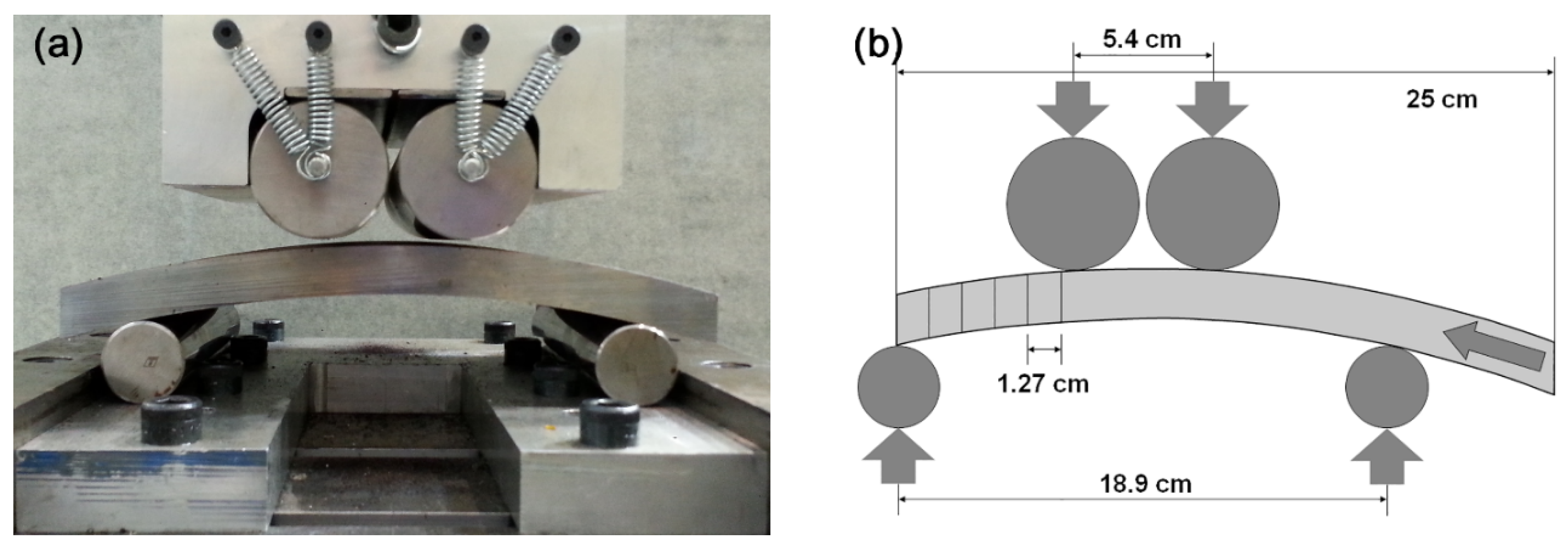
During pipe section flattening the applied stresses can vary significantly due to different factors such as flattening method, pipe size, wall thickness variations, and relative position within the pipe wall, e.g., at different through-thickness positions. These variations can easily cause strain localization. If the pipe section experiences localized “over-bending,” a region with reverse curvature can also be created and subsequent reverse deformation may be required to produce a flat section. Such strain reversals can contribute to the variability of mechanical properties measured from flattened pipe sections. Furthermore, without careful attention to avoid over-bending a particular section, the state of pre-strain is difficult to differentiate from that of a properly flattened section. In the current study, a unique flattening process was designed to obtain a flattened pipe with minimal strain localization in the flattened area. The flattening consisted of multiple bending steps performed with a four-point bending apparatus having a maximum load of 1000 kN. Prior to flattening, sections were cut from the two pipes with dimensions of 150 mm in the LD and 250 mm in the TD without altering the initial pipe wall thickness for each pipe.
Figure 1a is a photograph showing a pipe section ready for flattening located in the four-point bending apparatus.
Figure 1b is a schematic cross-section of the flattening fixture showing the pipe section and incremental loading scheme. The distance between the two upper rollers is 54 mm and the lower rollers are separated by 189 mm. The first load application occurred with the TD edge of the section aligned with one of the lower rollers. The load applied was controlled to create only a small amount of plastic bending strain. That is, a stress value just sufficient to yield the pipe was applied to the section. The section was unloaded and re-positioned (offset by approximately 12.7 mm) followed by another load application at the same load level as the first. This method was continued across (TD) the section until the other edge of the section was aligned with the opposite lower roller. The load was increased slightly at this position to achieve another small amount of plastic bending strain. The process was repeated by re-positioning the section with the same increments in the opposite direction. Over and back constituted one cycle and this procedure was repeated several times and flatness was checked at the conclusion of each cycle until a sufficiently large portion of the pipe section was flattened without over-bending the section plastically.
The result for both pipes was reasonable flatness (±0.1 mm over approximately 130 mm) in the center section. The applied load was primarily dependent on the section thickness and the YS: final load values of approximately 200 kN and 150 kN were applied to steel B and FP, respectively. The benefit of the flattening method used in the current study is that it minimizes local strain during flattening and should provide a relatively homogeneous strain distribution and therefore homogenous mechanical properties in the flattened section, to characterize fundamental property changes in an “idealized” flattening scenario. Other flattening methods considered included a similar procedure under 3-point bending as well as 4-point bending with very wide upper rollers. Both were discounted due to the relatively high strain localization under 3-point bending and the size of the available pipe section in 4-point bending to achieve a flattened area sufficient for further mechanical testing.
Samples for microstructural observation were cut from transverse cross-section (TC) orientations in both the as-received and flattened pipes. The samples were ground and polished using conventional methods, including a final step with 1 μm diamond suspension. The polished specimens were etched using a 2% nital solution. Scanning electron microscopic (SEM) observation of the samples was done with a field-emission SEM (FE-SEM, JEOL 7000F, JEOL Ltd., Tokyo, Japan). Five positions for steel FP and six positions for steel B through the thickness (corresponding to the positions used for tensile testing) were examined metallographically. Samples were repolished and Vickers hardness numbers were obtained using a microhardness tester (Model MHT200, LECO Corp., St. Joseph, MI, USA) with a 9.8 N load and 10 s dwell time. Triplicate tests were performed along the thickness direction for each sample. The size of each indent was about 100 μm in length and 100 μm in width.
To investigate the changes in tensile deformation behavior of the specimens in response to pipe section flattening, tensile test specimens were prepared for two different conditions: “as-received pipes” and “flattened pipes.” Both the LD and TD tensile test specimens for the as-received pipes were round sub-sized tensile specimens [
13] having a gauge length of 25 mm and a diameter of 6.25 mm. This was the largest specimen size available in the TD from the as-received pipes without flattening. This specimen geometry was selected to minimize the effect of specimen position; due to curvature of the as-received pipes, the gauge section of the round tensile specimens in the TD was located nearest the ID surface of the pipe while the gauge section of specimens in the LD was from the center region of the pipe wall. The specimen geometry was kept the same for the LD.
In an effort to determine tensile properties with respect to through-thickness position, rectangular flat sub-size tensile specimens were prepared from the flattened pipe sections by electrical discharge machining (EDM) [
13]. Before the EDM, both surfaces were ground approximately 0.6 mm to remove surface oxide layers.
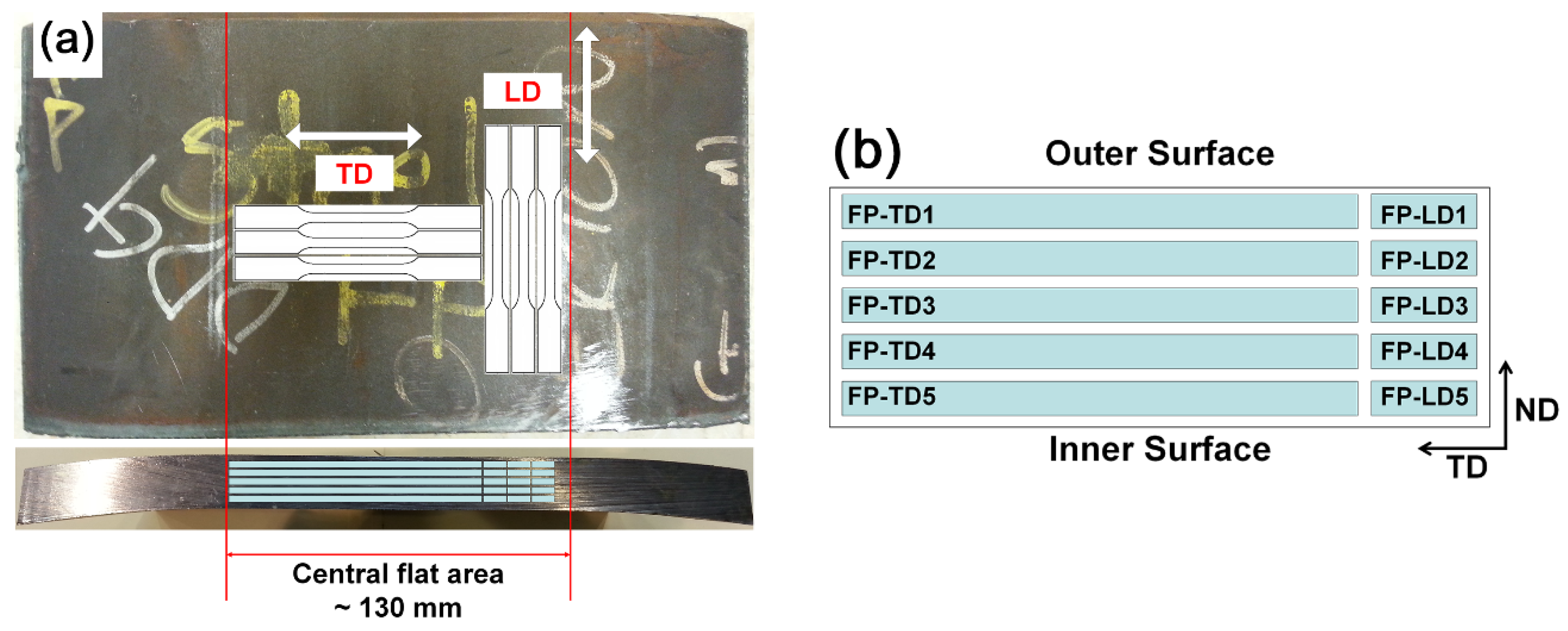
Figure 2a shows a flattened pipe section of steel FP that has about 130 mm of the central area flattened in the TD. Rectangular sub-size tensile specimens machined according to ASTM A370, with a gauge length of 25 mm, width of 6 mm, and a thickness of 2.5 mm were then obtained along the LD and the TD and through the thickness at different through-thickness positions (
Figure 2b). The gap between specimens was approximately 0.6 mm.
Due to the different thicknesses of the pipes (19.1 mm for steel B and 15.9 mm for steel FP), six different positions through the thickness were used for steel B and five positions for steel FP. The specimen closest to the outer diameter (OD) surface was designated as position 1 and the number increases going toward the inner diameter (ID) surface of the sections. For example, a tensile specimen from steel FP along the TD closest to the OD surface is designated FP-TD1 and closest to the ID surface is designated FP-TD5. Each location included triplicate tensile tests conducted at a displacement-controlled rate of 1.27 mm per min. For the 25 mm gauge length, this corresponds to an elastic strain rate of 8.47 × 10⁻⁴ s−1. The gauge section was monitored using a 25.4 mm extensometer with a strain limit of 50%. This specimen design allowed assessment of through-thickness property variations associated with pipe flattening. The YS was determined using the 0.2% offset method.
For reference,
Table 2 shows the strain histories applied to the sections during UOE pipe forming (U-ing, O-ing, and expansion), pipe flattening, and tensile testing. The principal direction of strain applied during pipe forming and pipe flattening is in the TD with the pre-strain amounts dependent on the position in the pipe due to the curvature. During the U-ing and O-ing the pre-strain is compressive at the ID of the pipe and tensile at the OD of the pipe. During the expansion process, tensile pre-strain is applied through the full thickness. The flattening process creates a tensile pre-strain at the ID of the pipe and compressive pre-strain at the OD of the pipe. There are thus four possible transverse strain histories depending on the specimen location through the thickness and tensile test orientation (LD or TD).
3. Results and Discussion
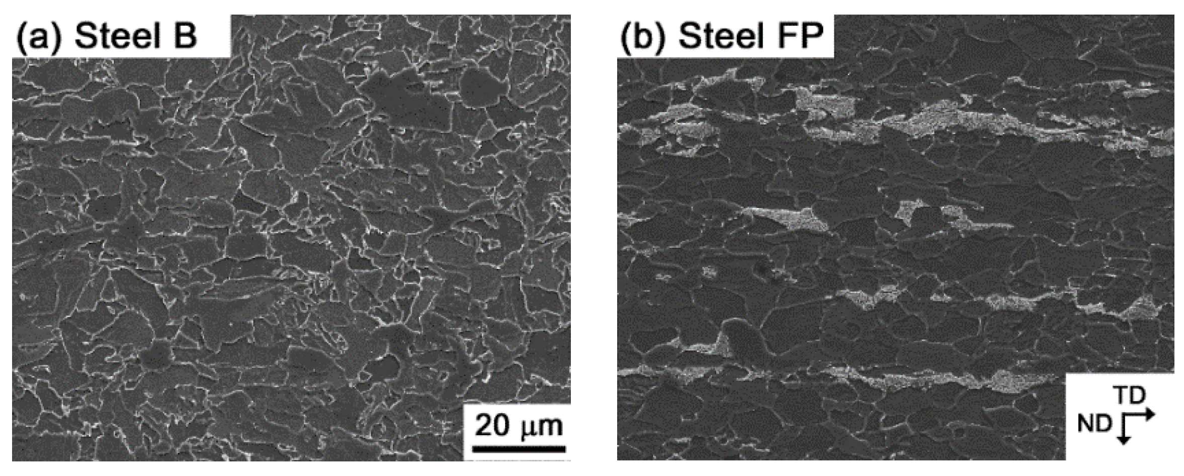
Figure 3 shows FE-SEM images of as-received microstructures for steel B and steel FP. These images were obtained from the transverse cross-section at position 3 of the mid-thickness area. The microstructure of steel B resembles a typical granular bainite microstructure (
Figure 3a) with irregular shaped (non-polygonal) ferrite grains, along with a small fraction of carbon enriched secondary constituents. Steel FP exhibited a banded microstructure composed of polygonal ferrite regions along with lighter pearlite bands elongated parallel to the TD (
Figure 3b). The evolution of microstructure through the thickness direction does not exhibit any notable variation in either steel, reflecting uniformity of the microstructure in these steels.
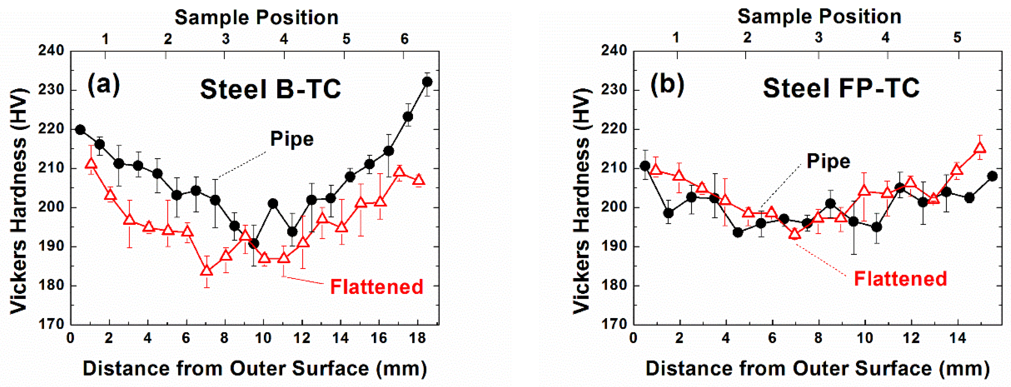
Figure 4 shows the Vickers hardness profiles for both as-received and flattened pipe samples through the thickness direction. Steel B in the as-received condition has a clear V-shaped hardness distribution (
Figure 4a), whereas the corresponding profile for steel FP exhibits less dependence on the through-thickness position (
Figure 4b). The shapes of the hardness profiles are similar after pipe flattening. While the average hardness values for steel B tend to be
reduced slightly by flattening, the hardness values in steel FP are less influenced by flattening. There is a possibility that pipe flattening “releases” some of the residual stress generated by pre-strain related to the pipe forming, because the strain applied during the flattening process is opposite to the pipe forming strain. However, the result varies with microstructure.
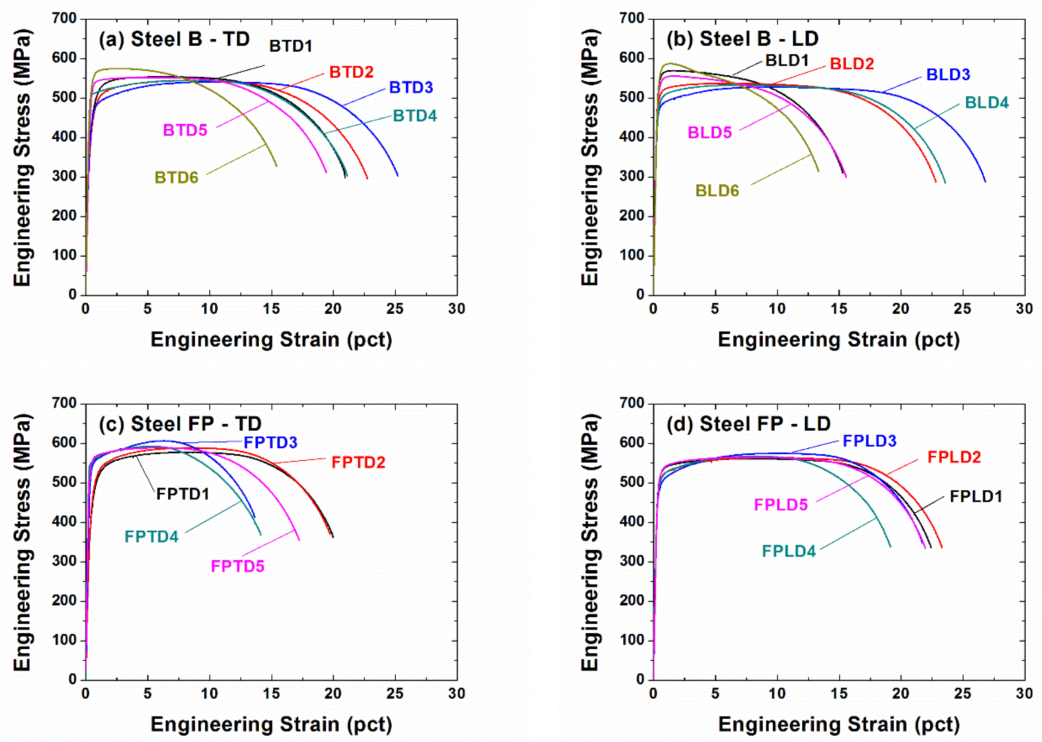
Figure 5 shows representative tensile stress-strain curves for steel B and steel FP after pipe flattening, tested in both the TD and the LD. The flattened pipes were sectioned and the numbers after the sample name indicate through-thickness position. All the stress-strain curves exhibit continuous yielding with position- and orientation-dependent variations on YS and UE. In particular, the YS and total elongation (TE) in steel B are strongly dependent on the through-thickness position.
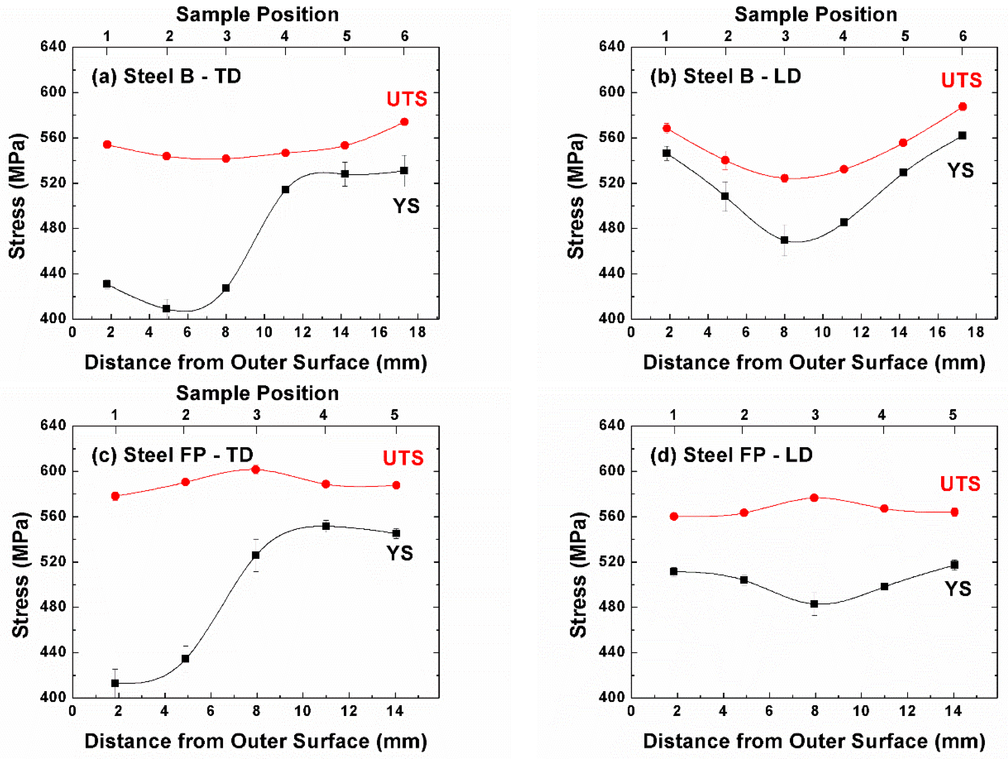
Figure 6 shows the average YS and UTS values from triplicate tensile tests as a function of position through the thickness of the pipe.
The YS values for both steels in the TD are substantially lower in the OD specimen location of the pipe as compared to the ID specimen location (
Figure 6a,c). Considering the pipe flattening process and related pre-strain characteristics as shown in
Table 2, the lower YS values in the OD specimen location of both TD specimens are most likely due to a Bauschinger effect (softening) associated with strain reversal [
14] since there is a compressive pre-strain during flattening of the sections nearest the OD surface just prior to tensile evaluation. The higher YS values for specimens nearest the ID surface of the pipe result from work hardening due to tensile pre-strain during the flattening procedure.
In the LD, the overall YS profile through the thickness for both steels is similar to the hardness profile. The profile is V-shaped with the variation of YS being greater for steel B as compared to steel FP (
Figure 6b,d). During flattening, the amount of pre-strain is zero at the mid-thickness position and increases in either tension or compression toward either surface. At both surfaces, the direction of pre-strain is normal to the tensile test direction, resulting in greater work hardening near both surfaces, but no Bauschinger effect. The YS evolution behaviors clearly show that large variation of the tensile properties can occur in the flattened pipe sections.
The UTS values in
Figure 6 are much more similar between the LD and TD results, and thus do not exhibit the Bauschinger effect noted in the yield strength results. In both directions, steel B shows slightly increased UTS values from the center toward both surfaces, while the UTS of steel FP was highest at the mid-thickness position for both test orientations.
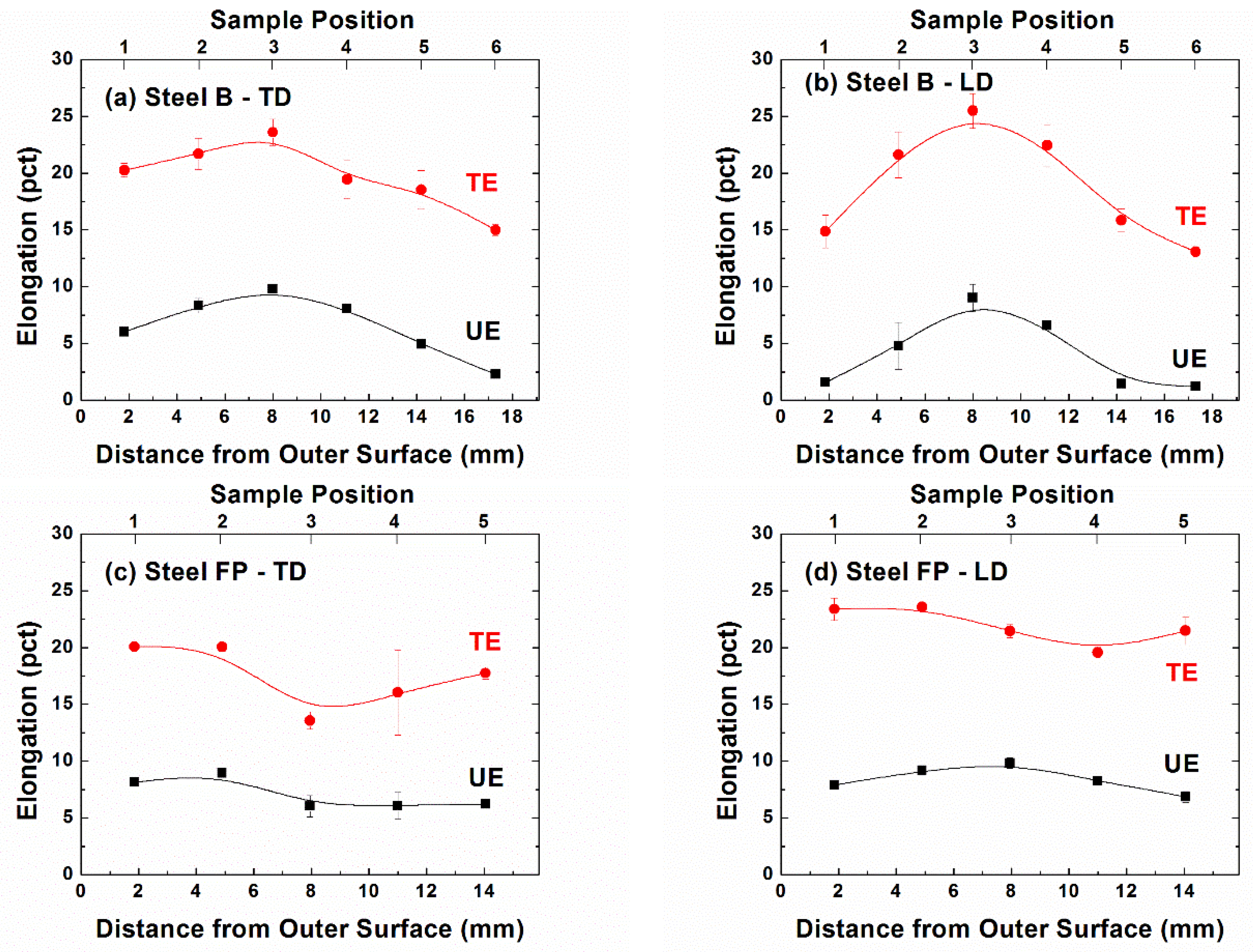
Figure 7 presents the corresponding UE and TE values through the thickness. The variations in UE and TE values are also influenced by the specimen microstructure and through-thickness position. The elongations in steel B decrease for positions away from the mid-thickness, and the effect is slightly greater on the UE for the LD. For example, steel B-LD exhibits a difference of more than 7 strain percent between position 3 and position 6. In contrast, steel FP shows less variation in the UE and TE values across all the specimen positions. In steel FP-LD, the difference between the maximum and minimum UE values through the thickness direction is less than 3 strain percent. Overall, the elongations seem to be inversely correlated with the specimen UTS values, whereas it is difficult to identify any clear relationship between the elongations and YS values. Despite the large variation in the tensile properties, about 15% post-uniform elongation (difference between the TE and UE values) is maintained for all experimental conditions examined in the current study. The reduction of UE at both surfaces for steel B-LD perhaps reflects a more limited work hardening capacity (UTS-YS) remaining in the bainitic steel. At both surfaces for steel B-LD, the YS values are greatly increased by flattening, and the difference between the flow stress and UTS values is diminished.
The experimental results show that there are large variations of the tensile properties in flattened pipes through the thickness and the variations are significantly influenced by the orientation and microstructure. In particular, steel B exhibited greater variation of the tensile properties through the thickness. These effects are highly relevant to the application, and are of a magnitude that can influence the ability to meet product specifications, even using the carefully controlled flattening procedure employed in the laboratory.
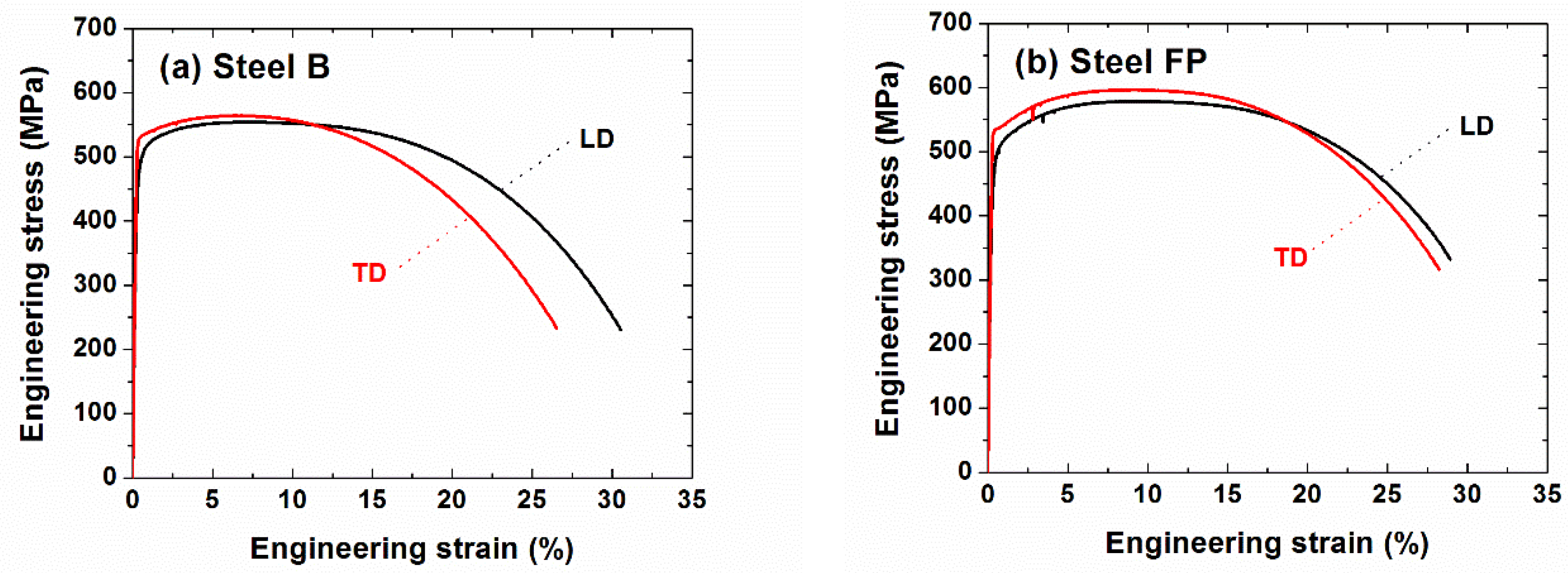
To examine further the effect of flattening, tensile tests were performed using as-received pipe specimens (without flattening) and the results are shown in
Figure 8. Regardless of the microstructure and orientation, the stress-strain curves of the as-received state are similar to each other. There is limited work hardening capacity, below 100 MPa, but large post-uniform elongation. However, TD specimens of both pipes have slightly higher strength and lower elongation values compared to the LD specimens.
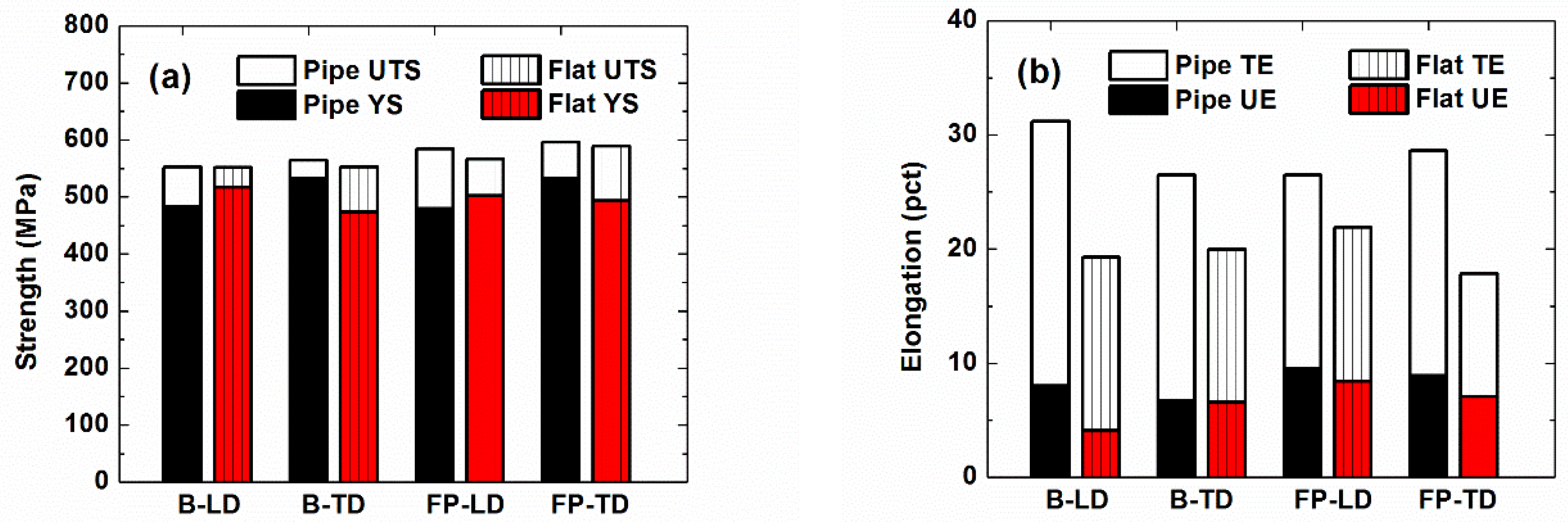
Figure 9 shows a comparison of the as-received and flattened pipe tensile properties. Tensile properties for the flattened sections were obtained by averaging the position-dependent tensile properties and these values are compared to the as-received pipe tensile properties obtained from round specimens. The UTS values before and after the pipe flattening are very similar, while there is much more variation in the YS values (
Figure 9a). The YS values for the flattened sections are higher in the LD, but lower in the TD compared to the as-received steels. Reduced YS in the TD reflects the impact of the Bauschinger effect on the orientation-dependent YS variation, while the LD results presumably reflect work hardening.
In
Figure 9b, the UE and TE are both reduced after flattening for all experimental conditions. Part of the reduction in post-uniform elongation can be related to the effect of the round specimen geometry used for as-received pipe specimens. For example, results reported for ultrafine-grained Cu [
15] indicate that the TE and post-uniform elongation greatly increase with sample thickness, but the UE is almost independent of the thickness. Even considering the effect of sample geometry, however, there is a substantial reduction in the UE of steel B-LD due to flattening, indicating the dependence of the UE reduction on the sample microstructure and pre-strain orientation.
In the current study, most of the variations in the tensile properties due to flattening can be understood based on the characteristics of the flattening pre-strain. However, the large reduction of UE in the LD is only observed in steel B, implying that the variation cannot be explained only by the magnitude of the pre-strain. The influence of microstructure may relate to variations of work hardening associated with pre-strain. In
Figure 6b, steel B-LD showed a great increase of the YS near both surfaces while the UTS increase was more limited. This increase implies significant work hardening during flattening in steel B-LD, limiting the remaining work hardening capacity of the specimen. In contrast, steel FP-LD shows a smaller increase of YS near the surfaces and exhibits less variation in the UTS after pre-straining, indicating limited variation of the remaining work hardening capacity. This different work hardening behavior is consistent with behaviors reported by others. For example, Kumar et al. [
16] reported that steels with bainitic microstructures have higher work hardening rates than ferritic steels. Thus, there should be greater work hardening experienced by steel B during flattening than by steel FP. The increased work hardening decreases the uniform elongation in steel B after flattening to a greater extent. If the sections were to experience “over bending” from localized straining during “industrial” flattening, then an even greater reduction of the UE would be expected in comparison to the laboratory conditions employed here.


