Article

Effects of Tempering on the Microstructure and Properties of a High-Strength Bainite Rail Steel with Good Toughness

1
The State Key Laboratory of Refractories and Metallurgy, Hubei Collaborative Innovation Center for Advanced Steels, Wuhan University of Science and Technology, Wuhan 430081, China
2
School of Mechanical and Automotive Engineering, Nanyang Institute of Technology, Nanyang 473004, China
*
Author to whom correspondence should be addressed.
Metals 2018, 8(7), 484; https://doi.org/10.3390/met8070484
Submission received: 5 June 2018 / Revised: 21 June 2018 / Accepted: 22 June 2018 / Published: 25 June 2018
(This article belongs to the Special Issue Processing-Structure-Property Relationships in Metals)

Abstract

:
An advanced bainite rail with high strength–toughness combination was produced in a steel mill and the effects of tempering on the microstructure and properties of the bainite rail steel were investigated by optical microscopy, transmission electron microscopy, electron back-scattering diffraction and X-ray diffraction. Results indicate that the tensile strength, elongation and impact toughness were about 1470 MPa, 14.5% and 83 J/cm2, respectively, after tempering at 400 °C for 200 min. Therefore, a high-strength bainite rail steel with good toughness was developed. In addition, the amount of retained austenite (RA) decreased due to bainite transformation after low-temperature tempering (300 °C) and RA almost disappeared after high-temperature tempering (500 °C). Moreover, as the tempering temperature increased, the tensile strength of the rail head first decreased due to the decreased dislocation density and carbon content in bainite ferrite and the coarseness of bainite ferrite, and then increased because of carbide precipitation at high-temperature tempering. Furthermore, RA played a significant role in the toughness of bainite rail. The elongation and toughness of the rail obviously decreased after tempering at 500 °C for 200 min because of the disappearance of RA and appearance of carbides.

1. Introduction

At present, the pearlite rail is widely used in the construction of railways. The strength of pearlite rail steel can be improved to near 1300 MPa by chemical composition optimization and heat treatment [1,2,3]. This value is close to its upper limit in strength and the toughness of pearlite rail significantly decreases with the increase in strength. In order to meet the demands of the development of high-speed and heavy-loading railways, new-generation rail steels should have higher strength, higher toughness and better wear resistance.
Ultra-fine bainite steel, developed by Bhadeshia and his coworkers, has a good combination of strength and toughness [4,5]. Research on the transformation behavior, microstructure evolution and mechanical property of ultra-fine bainite steels has attracted much attention [6,7,8,9,10,11]. Ultra-fine bainite rail steel has been developing in recent years. It is reported that the strength, toughness, fatigue life and wear resistance of bainite rail are superior to those of pearlite rail [12,13,14,15]. In addition, lower carbon content in bainite rail ensures better welding performance. Therefore, bainite rail steel is a promising substitution for the next generation of rail steels.
Some researchers focused on the optimization of chemical composition of bainite rail and the microstructure–property relationship in bainite rail [16,17,18,19]. Wang et al. [16] designed a bainite rail with the chemical compositions of 0.22C–2.0Mn–1.0Si–0.8Cr–0.8(Mo + Ni) (wt %). They found that the toughness of bainite rail steel is closely related to the stability of retained austenite [16,17]. Gui et al. [18] reported that thin film-like retained austenite plays a significant role on the crack propagation of rolling contact fatigue. Zhang et al. [19] studied the hydrogen embrittlement of bainite rails and their results indicated that the content of hydrogen should be lower than 7 × 10⁻⁵ wt % in order to avoid hydrogen embrittlement.
The residual stress in bainite rail is usually larger than that in pearlite rail. In order to relieve the residual stress and further improve the toughness of bainite rail, tempering is usually necessary treatment. Wang et al. [16] developed a tempered bainite rail steel with tensile strength of 1388 MPa. However, the study on the effects of tempering on the microstructure and properties of bainite rail is very limited. More investigations on tempered bainite rail are needed to improve the properties and optimize tempering technology.
Therefore, in the present study, the tempering treatments were conducted and the effects of tempering on the microstructure and properties of the bainite rail were analyzed. A 1500-MPa-grade bainite rail with high strength–toughness combination was developed and produced in the industrial production line.

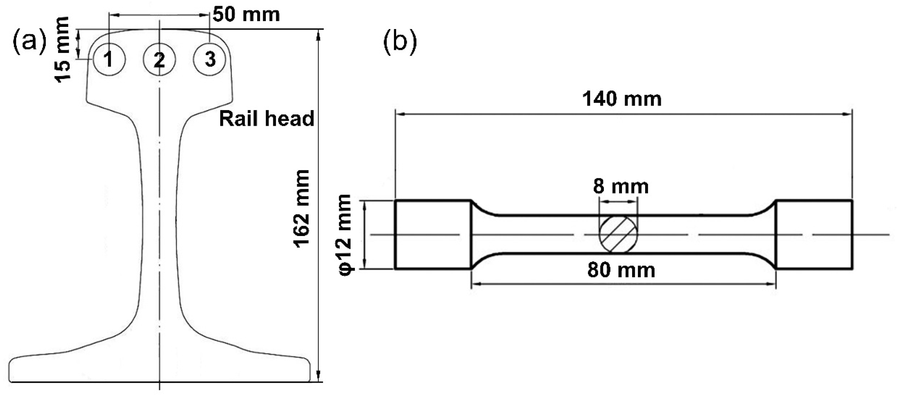
2. Materials and Methods

The chemical compositions of the tested steel are given in Table 1. The continuously cast billets were heated to 1250 °C in 210 min. Then, the billets (200 mm × 380 mm × 7000 mm) were hot rolled to rails on a rail mill in an industrial production line, followed by air cooling (about 0.8 °C/s) to room temperature. The beginning and finishing temperatures of rolling were 1150 °C and 910 °C, respectively. For tempering experiments, samples 300 mm long were cut from the hot-rolled rail and the cross-sections of the tempering samples were the same as the rolled rail. The tempering temperatures were set to be 300 °C, 350 °C, 400 °C, 450 °C and 500 °C, respectively, and the tempering time was 200 min.
In order to examine the mechanical property of the rail head, specimens for tensile and V-notched impact tests were cut from as-rolled and tempered rail heads (Figure 1a). The size of tensile sample is shown in Figure 1b and sample size for impact tests was 5 mm × 5 mm × 100 mm. The tensile tests were conducted on UH-F500KNI materials testing machine at the speed of 0.1 s−1 and impact tests were carried out at room temperature on ZBC24523 impact tester. Duplicate tests were performed for each specimen to improve the accuracy. The microstructure was observed by optical microscopy (OM, Zeiss, Oberkochen, Germany) and transmission electron microscopy (TEM, JEOL, Tokyo, Japan). Thin foils for TEM observation were cut from the bulk specimens, and then mechanically ground to about 40-μm thickness. The specimens were further thinned using a twin-jet electro-polisher with an electrolyte consisting of 10 vol % perchloric acid and 90 vol % glacial acetic acid. X-ray diffraction (XRD, Panalytical, Almelo, The Netherlands) was used to determine the volume fraction and carbon content of retained austenite (RA). Electron back-scattering diffraction (EBSD, FEI, Hillsboro, OR, USA) was used to distinguish different phases.

3. Results and Discussions
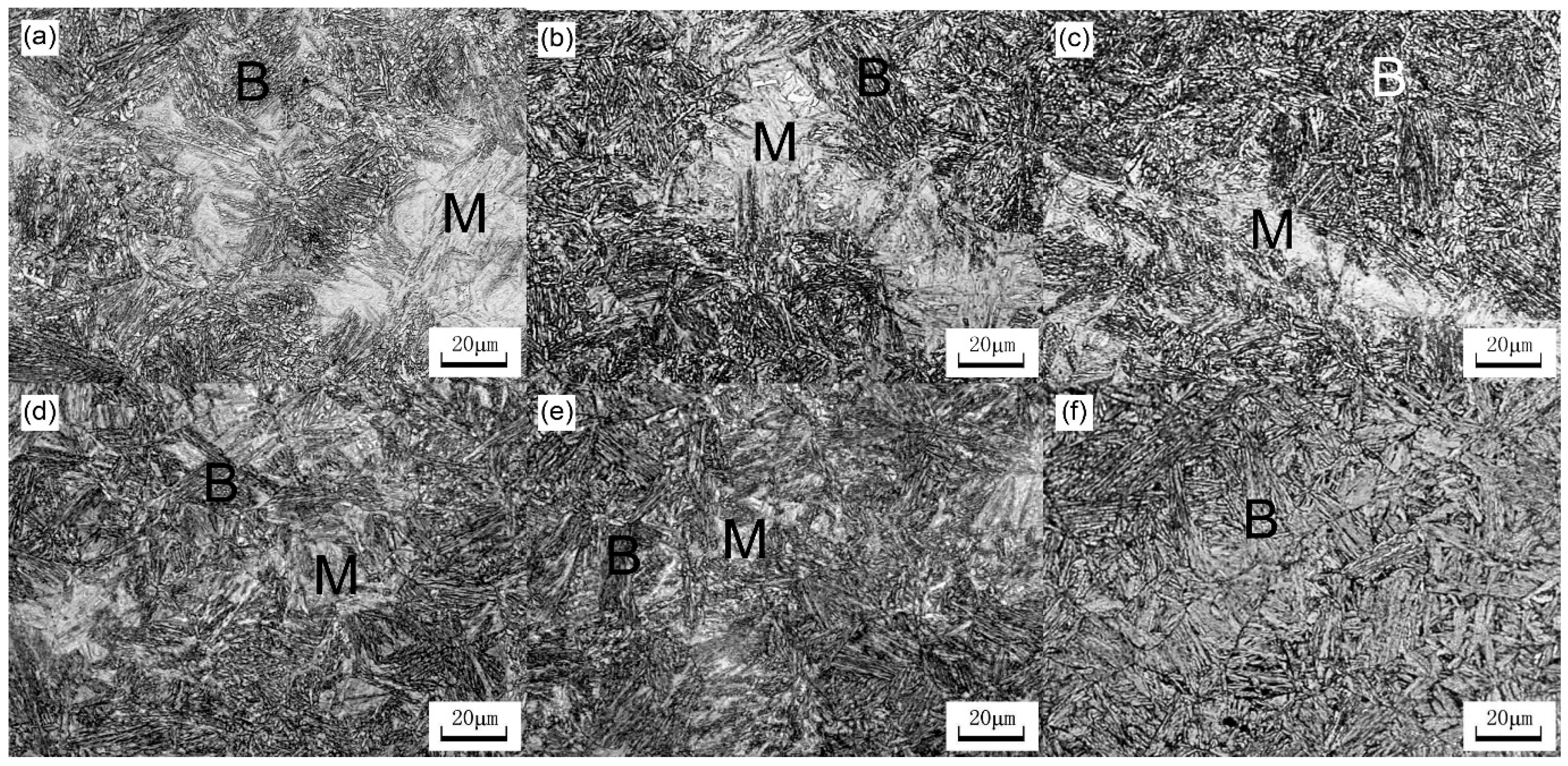
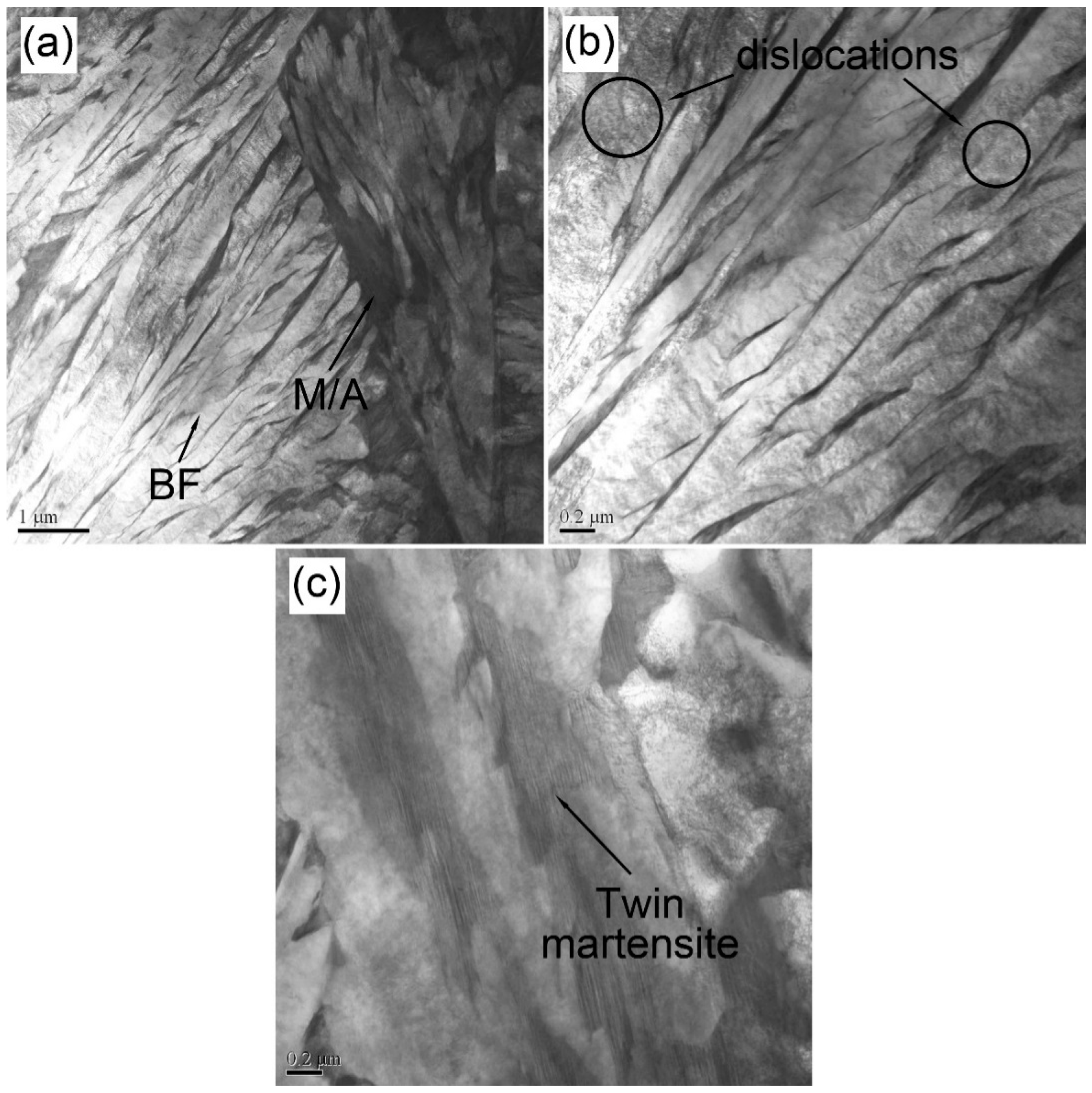
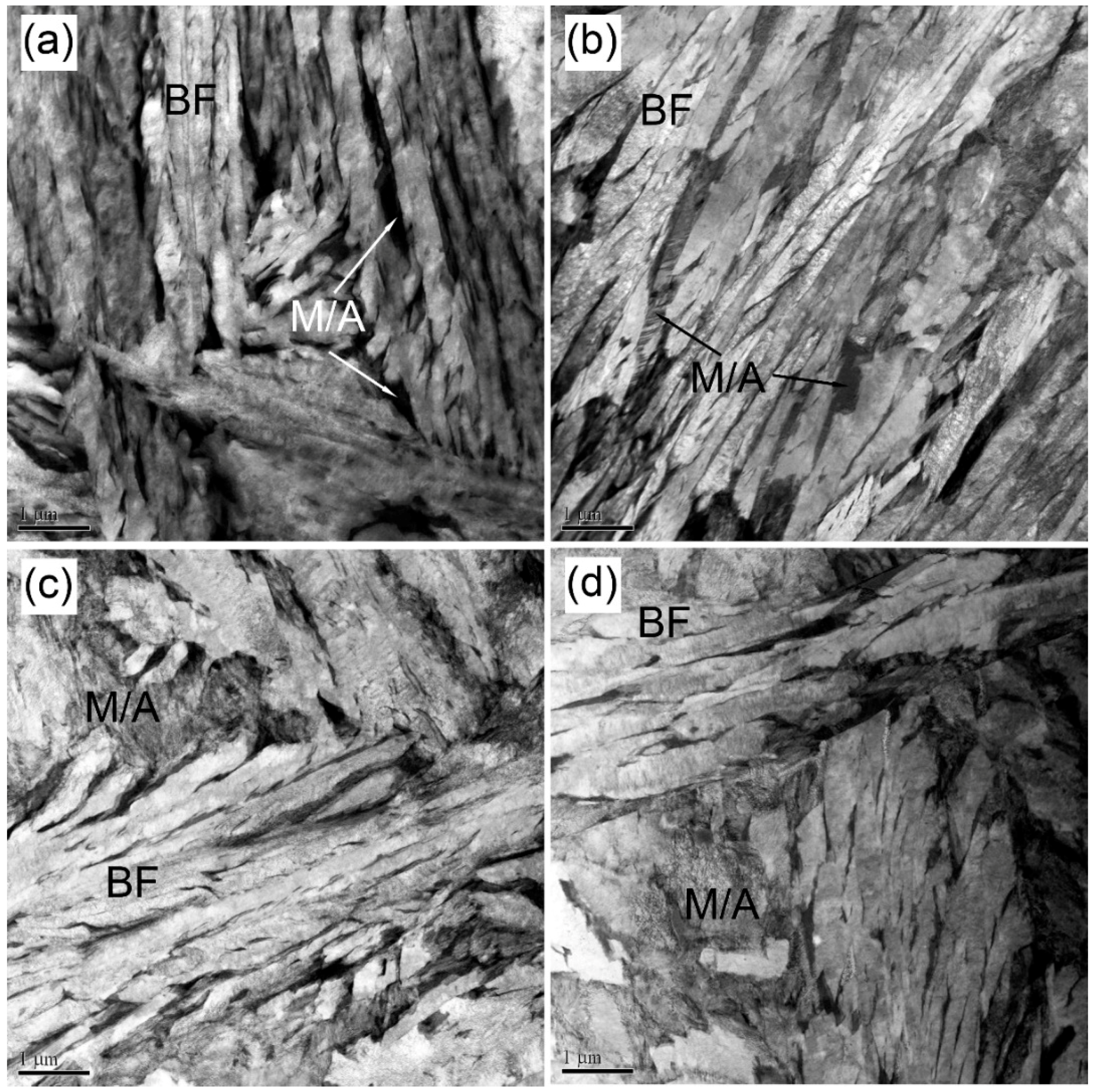
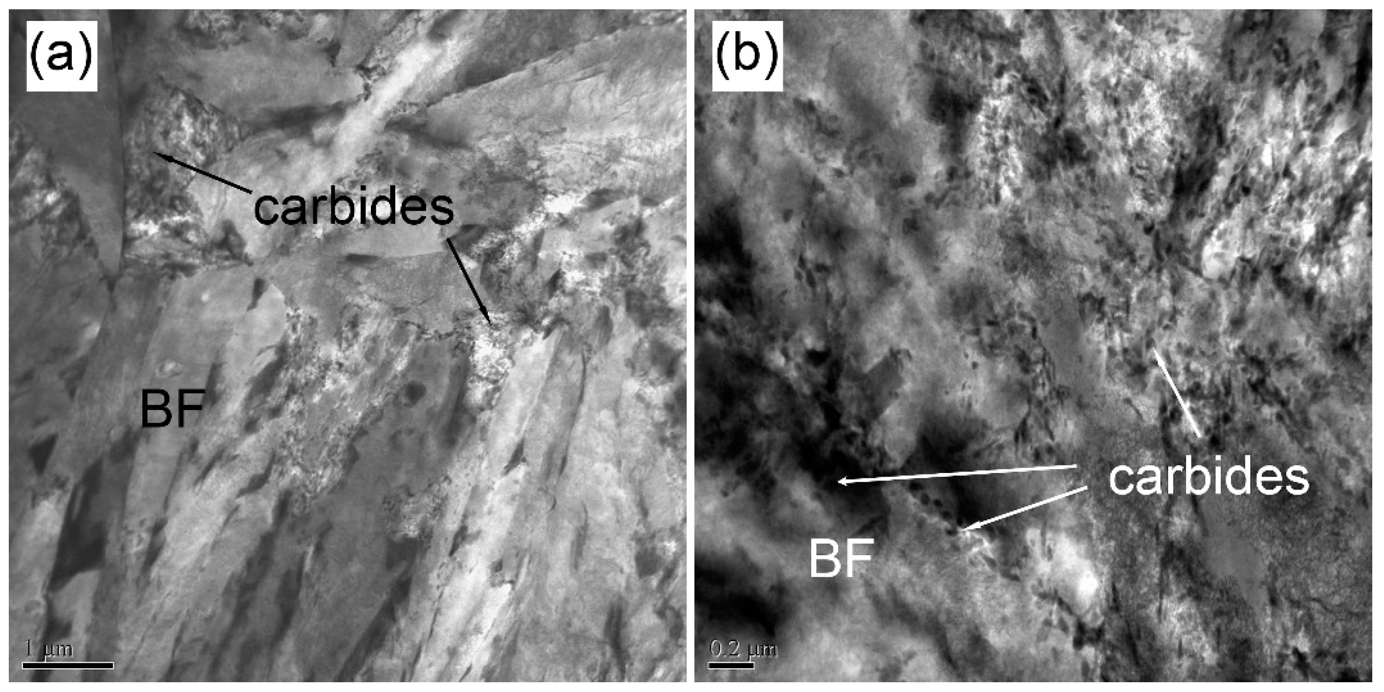
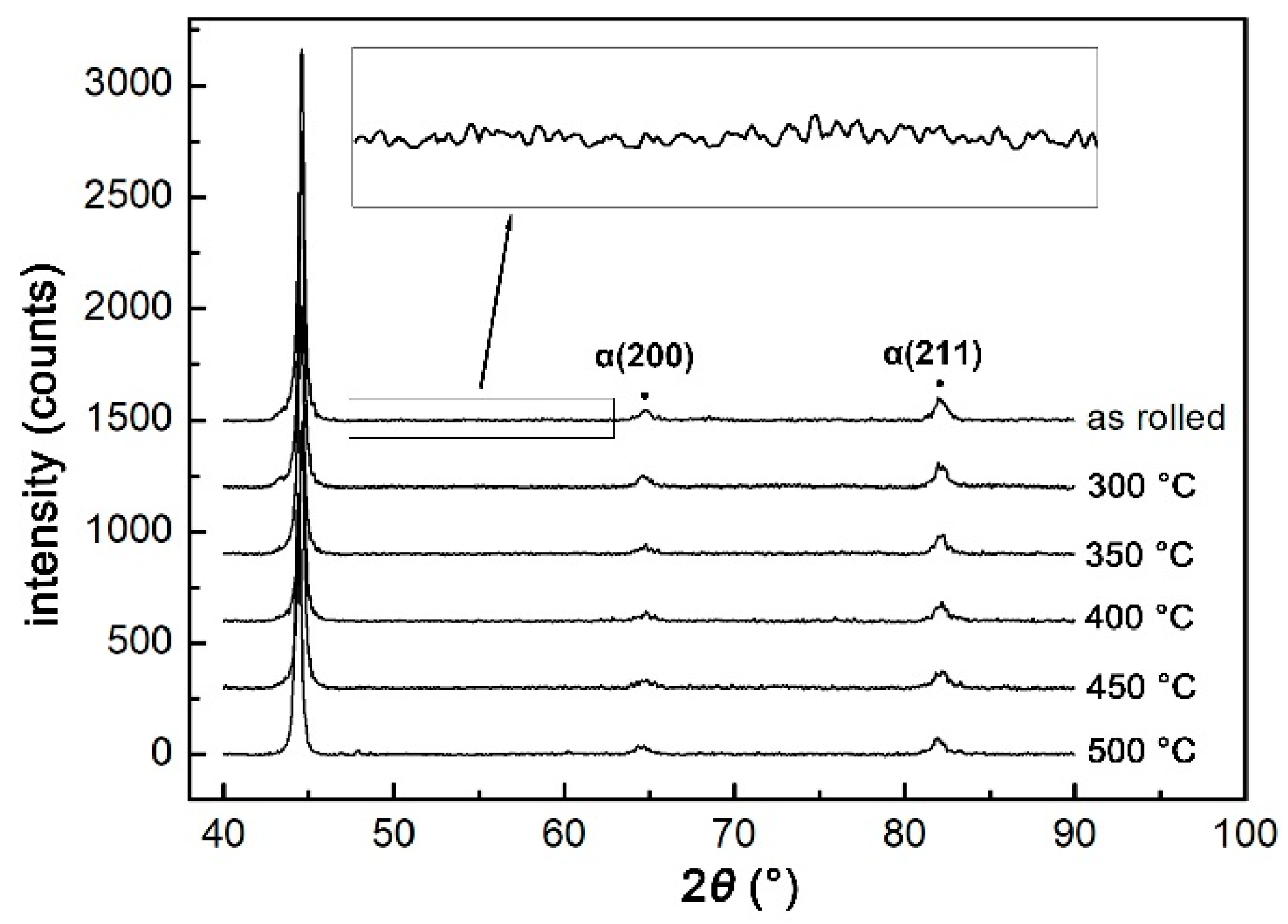
3.1. Microstructure

Figure 2 displays the OM microstructures of as-rolled and tempered rail heads and corresponding EBSD graphs are given in Figure 3. The microstructure consisted of bainite (B) and martensite/austenite (MA) constituent in all samples. Bainite showed lath-like morphology and MA was blocky. It is observed in Figure 2 that compared with hot-rolled bainite rail, when the tempering temperature was lower (300 to 400 °C), the morphologies of bainite and martensite had no significant change. As the tempering temperature increased, the amount of M/A decreased and bainite sheaves became coarser, especially for 500 °C tempering.
It was difficult to distinguish RA in the OM micrograph, whereas EBSD graphs (Figure 3) clearly showed the blocky morphology of RA (yellow). It is reported that thin RA films distribute between bainite laths in ultra-fine bainite steels [20,21], but thin RA was hardly observed in EBSD graphs (Figure 3) because of the lower magnification in EBSD graphs. The defect density in bainite is smaller than that in martensite. If two phases are crystallographically similar, but different in defect content, band slope can be used to discriminate phase content based on the database in EBSD analysis software. Thus, bainite and martensite with similar lattice structure were distinguished to be red and green in Figure 3 by EBSD.
Figure 4, Figure 5 and Figure 6 exhibit the TEM micrographs of bainite rail steel. Lath-like bainite ferrite (BF), twin martensite (Figure 4c) and M/A were observed in the as-rolled rail. There were many dislocations within the bainite laths (circled area in Figure 4b), which strengthened the bainite structure. When the tempering temperature was lower (300–350 °C, Figure 5a,b), bainite morphology had no obvious difference from the as-rolled rail. As the tempering temperature increased (400–450 °C, Figure 5c,d), the dislocation density decreased and the bainite ferrite slightly coarsened. When the tempering temperature was 500 °C, a large amount of carbides separated out (Figure 6). Most carbides precipitated from M/A, some carbides distributed between bainite ferrite and a small amount of carbides distributed within BF.

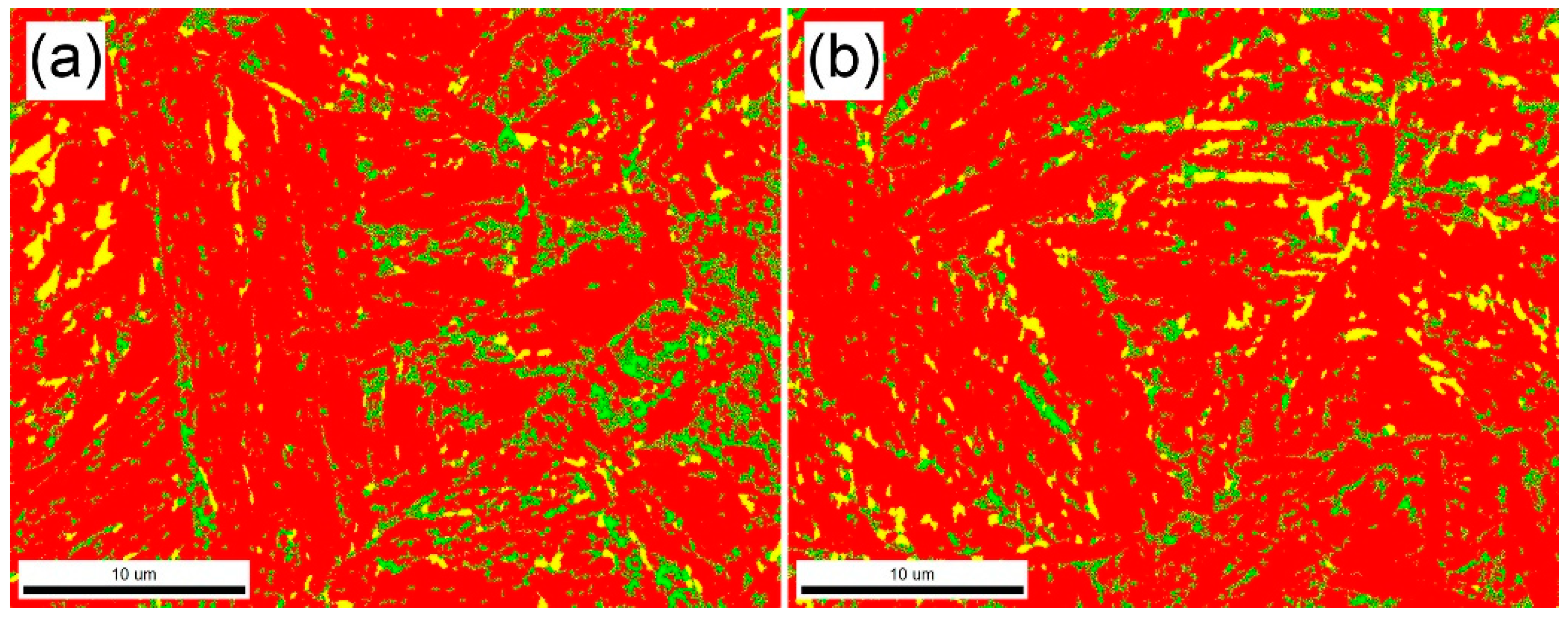
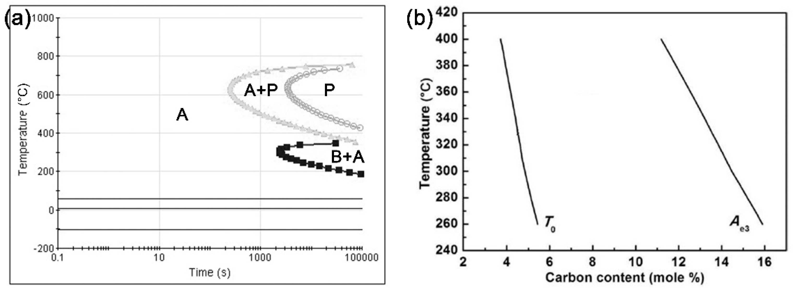
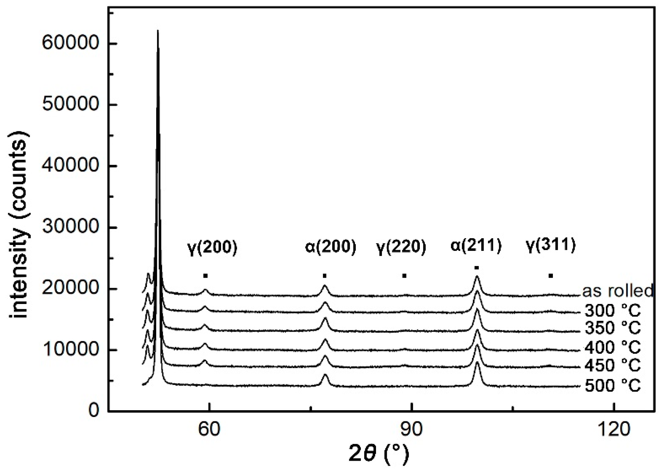
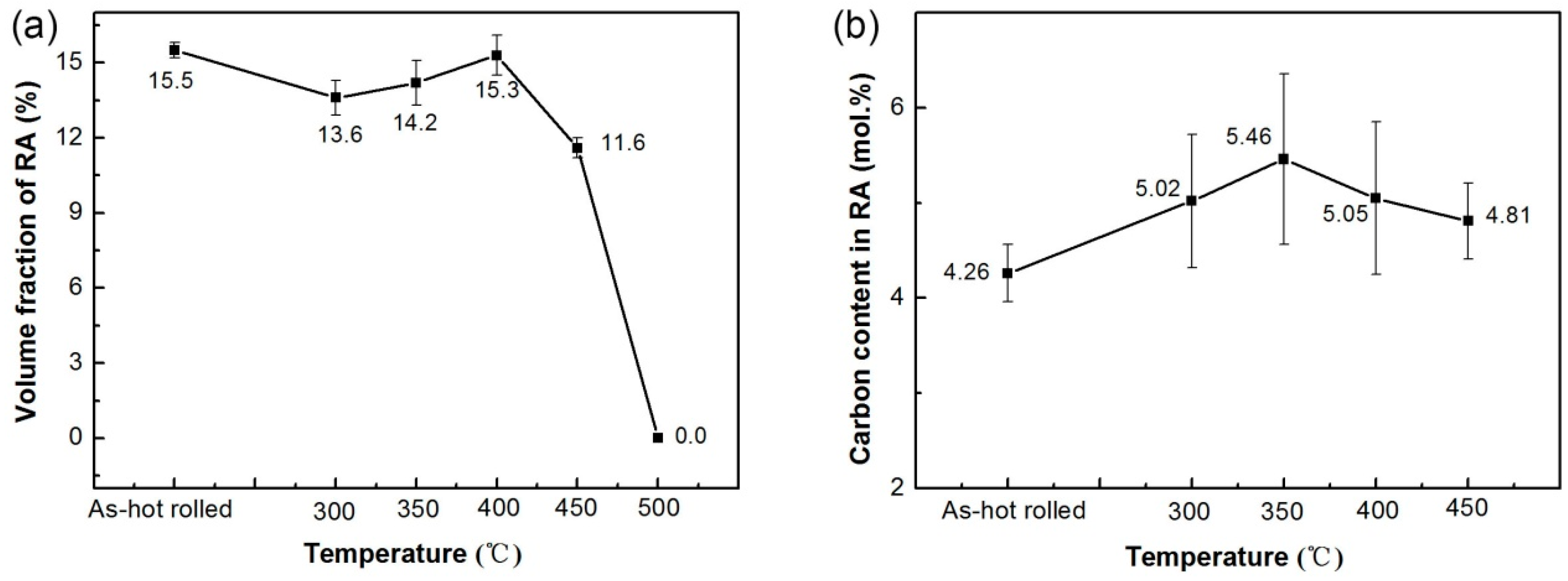
3.2. Retained Austenite

In order to accurately determine the volume fraction of RA, XRD experiments were conducted. Diffraction peaks are shown in Figure 7. The volume fractions of RA (VRA) and the carbon contents in RA (CRA) were calculated based on the integrated intensities of (200) α, (211) α, (200) γ, and (220) γ diffraction peaks, and the angles of (200) and (220) austenite peaks, respectively, according to the method proposed in Refs. [11,22]. The results are shown in Figure 8a. It is obvious that compared to the as-rolled rail, the RA amount slightly decreased by tempering at low temperatures (300 °C and 350 °C). Tempering at middle temperature (400 °C) had no significant effect on the RA amount. However, the RA amount in the specimens tempered at high temperatures (450 °C and 500 °C) decreased, and this decrease was evident at 500 °C (no RA was detected). In general, RA in the tested steel was relatively stable during tempering below 400 °C.
It is known that RA may decompose to other microstructures such as ferrite, bainite, martensite and carbides during tempering [23]. The carbon contents in RA were calculated by Equation (1) [16] according to the location of austenite peaks and results are shown in Figure 8b:
αγ = 0.3556 + 0.00453xc + 0.000095xMn + 0.00056xAl,
where αγ is the austenite lattice parameter (nm), and xc, xMn and xAl are the concentrations of carbon, manganese and aluminum in austenite (wt %), respectively. The manganese and aluminum concentrations are the original contents in the tested steel. It is noted that the coefficients (0.000095 and 0.00056) before xMn and xAl in Equation (1) are too small to obviously affect the calculation of carbon content in RA, so the effects of Mn and Al concentrations on the carbon content in RA could be ignored normally.
According to the carbon content of RA and the contents of other alloy elements in as-rolled rail, the bainite transformation starting temperature (Bs), martensite transformation starting temperature (Ms) and time–temperature–transformation (TTT) curves of the RA for as-rolled rail were calculated using the JMatpro software [24] and the results are shown in Figure 9. The size of RA was very small and RA should contain many dislocations due to the displacive nature of bainite transformation. It is known that finer austenite is more stable than the larger one [25,26]. Besides, it is reported that intense dislocation debris around the bainite/austenite interface hinders the interface immobile and bainite transformation [27]. These microstructural characters of RA have strong influence on its stability. The microstructure effect was not considered during calculation. Therefore, the real bainite transformation kinetics should be slower than that of the calculated one (Figure 9a). Bs and Ms were 355 °C and 56 °C, respectively. All tempering temperatures were higher than Ms, so that RA hardly decomposed into martensite during the tempering of the hot-rolled rail. In addition, tempering temperatures of 300 °C and 350 °C were below Bs, so that bainite transformation might occur at these temperatures. The TTT curve (Figure 9a) displays that the incubation period of bainite transformation at 300 °C is about 40 min, which is shorter than the tempering time (200 min), so that the bainite transformation can happen. Therefore, the decrease in RA amount after tempering at 300 °C and 350 °C was mainly caused by the decomposition of RA into bainite during tempering. It should be noted that carbon can diffuse from bainite ferrite and martensite into RA during tempering and bainite transformation, leading to the higher stability of RA. When the carbon content in RA reaches the T0 curve (Figure 9b), at which the free energy of austenite equals that of ferrite, bainite transformation ceases [28]. Thus, only a part of RA transforms to bainite. When the tempering temperature was 400 °C, there was no obvious carbide precipitation (Figure 5), so that the RA was too stable to decompose into other phases during tempering. As a result, the RA amount in the steel tempered at 400 °C was similar to that in the as-rolled steel. For tempering at high temperature (500 °C), there were large amounts of fine carbides in the microstructure (Figure 6), which significantly decreased the stability of RA, so that almost all RA decomposed during tempering and there was no RA detected in XRD experiments (Figure 7).
As the tempering temperature increased, the carbon content in RA first increased and then decreased (Figure 8b). Compared with the as-rolled rail, the carbon content of RA in the tempered rail was larger due to the diffusion of carbon from bainite and martensite into austenite [23,24]. This means that the RA became more stable after tempering because the stability of RA was largely influenced by its carbon content. As the tempering temperature increased, there were two factors influencing the carbon content in RA. On the one hand, the diffusion of carbon into austenite increased its carbon content. On the other hand, carbide precipitation from austenite decreased its carbon content. When the tempering temperature was low (below 350 °C), no carbides were formed (Figure 5), so that the carbon content of RA increased with the tempering temperature. However, when the tempering temperature was high (above 350 °C), the carbon content decreased with the increase of tempering temperature, indicating that some very small carbides were formed during the tempering at 400 °C or higher temperature. It should be noted that it is difficult to observe carbides in TEM pictures for the specimens tempered at 400 °C and 450 °C due to the very small amount.

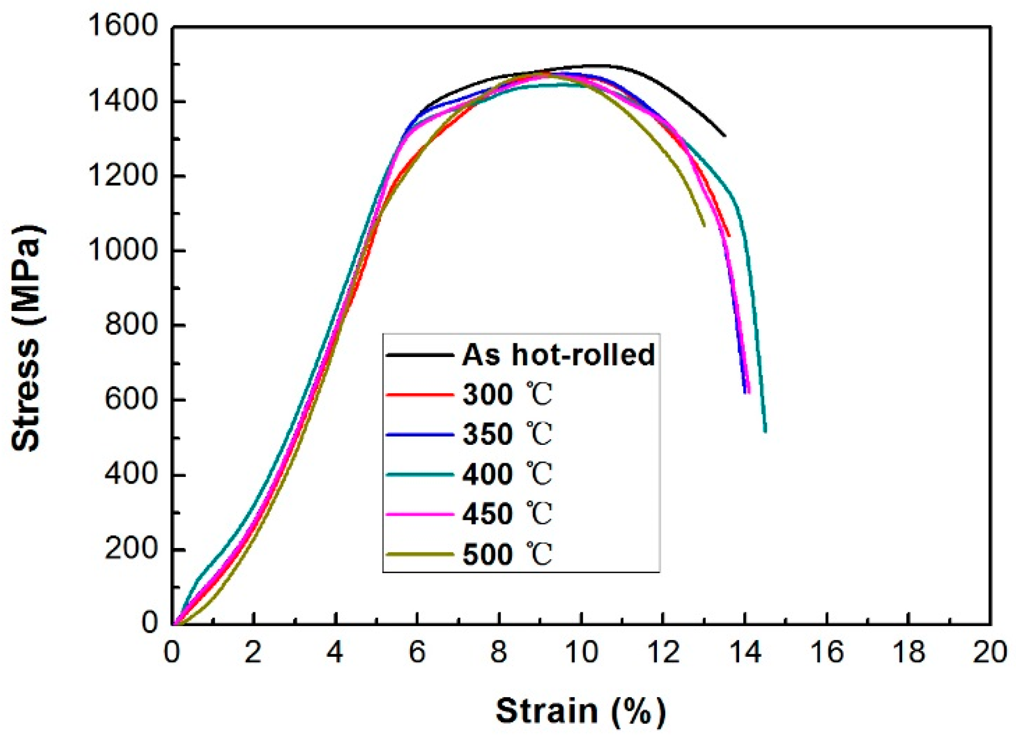
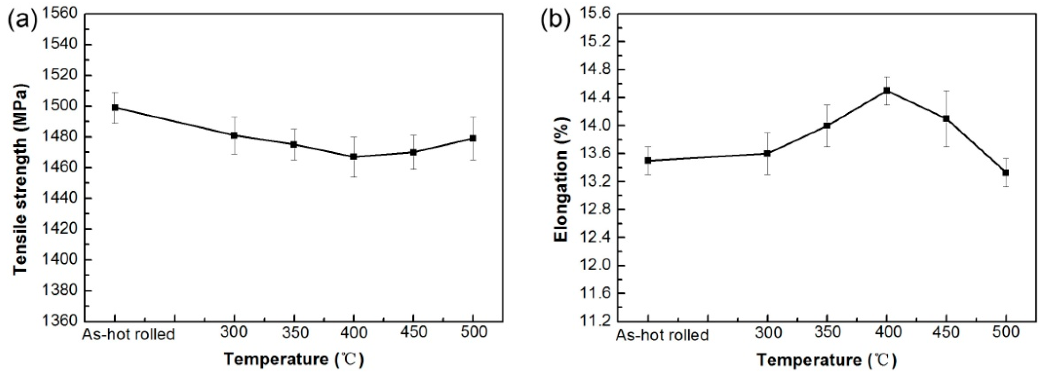
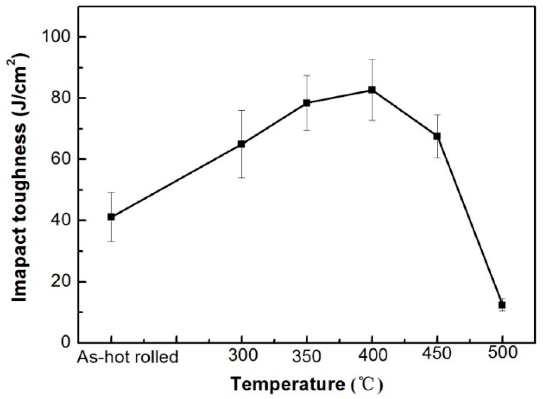
3.3. Mechanical Property

Figure 10 presents the engineering stress–strain curves of the hot-rolled and tempered specimens. The tensile properties of the as-rolled and tempered rail heads are also shown in Figure 11 for clear comparison. The uncertainties in Figure 11 are standard deviations. The tensile strength of as-rolled bainite rail was about 1470 MPa and the elongation was about 14.5%, which were obviously superior to those of conventional pearlite rails. With the increase of tempering temperature from 300 °C to 450 °C, the tensile strength decreased and the elongation increased. The high strength of bainite rail is mainly attributed to the ultra-fine bainite ferrite and high dislocation density in bainite ferrite. As the tempering temperature increased, the thickness of bainite ferrite slightly increased (Figure 4), the dislocation density in bainite ferrite decreased (Figure 4) and the carbon content in bainite ferrite decreased, so that the tensile strength decreased when the tempering temperature was below 450 °C. However, when the tempering temperature was 450 °C and 500 °C, more carbides separated out from M/A and bainite, which compensated for the decrease of strength, so the tensile strength of the bainite rail increased. In addition, the thickness of bainite ferrite increased and dislocation density decreased at the tempering temperature rose from 300 °C to 400 °C, resulting in the increase of elongation compared to hot-rolled rail. Compared to the specimen tempered at 400 °C, the elongation in the specimens tempered at 450 °C and 500 °C decreased due to carbide precipitation.
Figure 12 presents the impact toughness of the as-rolled and tempered rails. The impact toughness of as-rolled rail was about 41 J/cm2. The impact toughness obviously increased to 65 J/cm2 by tempering at 300 °C due to the relief of residual stress and the increased stability of RA which improved the TRIP effect. The impact toughness reached 83 J/cm2 when the tempering temperature was 400 °C. However, when the tempering temperature increased to 450 °C and 500 °C, the impact toughness of the rails significantly decreased, especially at 500 °C. The toughness of the rail was only 12 J/cm2 after tempering at 500 °C, demonstrating a brittle fracture. Figure 13 depicts the diffraction peaks of the samples after the tensile test. It is obvious that the austenite peaks disappeared in all samples after the tensile test, indicating that RA decomposed during the tensile test. The RA was transformed to martensite during the tensile test and thus increased the plasticity and toughness of the steel, which is called the transformation-induced plasticity (TRIP) effect [21,29]. The appearance of platform in the stress–strain curves confirmed the TRIP effect. There was no apparent platform in the stress–strain curves of specimens tempered at 500 °C, because almost all RA was decomposed during tempering at 500 °C. There was no TRIP effect due to almost zero RA (Figure 8), resulting in obvious decrease in impact toughness. Besides, the large amount of carbide precipitation at 500 °C also decreased the toughness.
Wang et al. [16] developed a tempered bainite rail steel with tensile strength of 1388 MPa and elongation of 16%. In the present study, a bainite rail with higher strength was developed. The tensile strength, elongation and impact toughness were about 1470 MPa, 14.5% and 83 J/cm2, respectively, after tempering at 400 °C for 200 min. Therefore, a high-strength bainite rail with good toughness was developed in the present study. Compared to the steel in [16] (0.22C–2.0Mn–1.0Si–0.8Cr–0.8(Mo + Ni) (wt %)), the steel in the present work (0.22C–1.5Mn–1.6Si–1.5Cr–0.41Ni–0.37Mo (wt %)) contained more Si and Cr to suppress the formation of brittle cementite and obtain high-strength carbide-free bainite. In addition, the amount of RA in this work (maximum ~15.5 vol %) was much larger than that in [16] (maximum ~8.8 vol %), which also improved the mechanical properties of bainite steel by the TRIP effect. Moreover, the maximum tensile strength of conventional pearlite rail is below 1300 MPa with inferior impact toughness. The mechanical property of the developed bainite rail is much superior to that of conventional pearlite rail.

4. Conclusions

An advanced bainite rail with high strength and good toughness was developed and produced in a steel mill. The tempering experiments were conducted and the effects of tempering on the microstructure and properties of the bainite rail were investigated. The following conclusions can be obtained:
(1)
The tensile strength, elongation and the impact toughness were about 1470 MPa, 14.5% and 83 J/cm2, respectively, after tempering for 200 min at 400 °C. A high-strength bainite rail steel with good toughness was developed.
(2)
When the tempering temperature was lower than 400 °C, the amount of RA decreased compared to the as-rolled rail due to the decomposition of austenite to bainite. At a middle tempering temperature of 400 °C, the RA was very stable during tempering. When the tempering temperature was 500 °C, a large amount of carbides precipitated and RA almost disappeared.
(3)
The tensile strength of the rail head decreased when the tempering temperature was lower than 450 °C due to the decreased dislocation density and carbon content in bainite ferrite and the coarseness of bainite ferrite. Carbide precipitation compensated for the decrease in strength when the tempering temperature was 450 °C and 500 °C. In addition, the elongation slightly increased and impact toughness was obviously improved at the tempering temperature from 300 °C to 400 °C. The impact toughness and elongation sharply decreased after tempering at 500 °C because of the appearance of carbides and absence of RA. Therefore, RA plays a significant role in the toughness of bainite rail by the TRIP effect.

Author Contributions

M.Z., doctoral student, conducted experiments, analyzed the data and wrote the paper; G.X., supervisor, conceived and designed the experiments; M.Z., doctoral students, conducted experiments and analyzed the data; Q.Y., doctoral students, conducted experiments and analyzed the data; J.T., doctoral students, conducted experiments and analyzed the data; H.H., doctoral students, conducted experiments and analyzed the data.

Funding

The Major Projects of Technological Innovation of Hubei Province (No. 2017AAA116), the National Natural Science Foundation of China (NSFC) (No. 51704217) and the National Natural Science Foundation of China (NSFC) (No. 51274154).

Conflicts of Interest

The authors declare no conflict of interest. The founding sponsors had no role in the design of the study; in the collection, analyses, or interpretation of data; in the writing of the manuscript, and in the decision to publish the results.

References

  1. Yates, J.K. Innovation in rail steel. Sci. Parliam. 1996, 53, 2–3. [Google Scholar]
  2. Debehets, J.; Tacq, J.; Favache, A.; Jacques, P.; Seo, J.W.; Verlinden, B.; Seefeldt, M. Analysis of the variation in nanohardness of pearlitic steel: Influence of the interplay between ferrite crystal orientation and cementite morphology. Mater. Sci. Eng. A 2014, 616, 99–106. [Google Scholar] [CrossRef]
  3. Tan, Z.L.; An, B.F.; Gao, G.H.; Gui, X.L.; Bai, B.Z. Analysis of softening zone on the surface of 20Mn2SiCrMo bainitic railway switch. Eng. Fail. Anal. 2015, 47, 111–116. [Google Scholar] [CrossRef]
  4. Caballero, F.G.; Bhadeshia, H.K.D.H. Very strong bainite. Curr. Opin. Solid State Mater. Sci. 2004, 8, 251–257. [Google Scholar] [CrossRef] [Green Version]
  5. Garcia-Mateo, C.; Caballero, F.G.; Bhadeshia, H.K.D.H. Development of hard bainite. ISIJ Int. 2003, 43, 1238–1243. [Google Scholar] [CrossRef]
  6. Zhou, M.X.; Xu, G.; Hu, H.J.; Yuan, Q.; Tian, J.Y. Comprehensive analysis on the effects of different stress states on the bainitic transformation. Mater. Sci. Eng. A 2017, 704, 427–433. [Google Scholar] [CrossRef]
  7. Long, X.Y.; Kang, J.; Lv, B.; Zhang, F.C. Carbide-free bainite in medium carbon steel. Mater. Des. 2014, 64, 237–245. [Google Scholar] [CrossRef]
  8. Zhou, M.X.; Xu, G.; Hu, H.J.; Yuan, Q.; Tian, J.Y. Kinetics model of bainitic transformation with stress. Met. Mater. Int. 2018, 24, 28–34. [Google Scholar] [CrossRef]
  9. Tian, J.Y.; Xu, G.; Zhou, M.X.; Hu, H.J.; Wan, X.L. The effects of Cr and Al addition on transformation and properties in low-carbon bainitic steels. Metals 2017, 7, 40. [Google Scholar] [CrossRef]
  10. Hu, H.J.; Xu, G.; Wang, L.; Xue, Z.L.; Zhang, Y.L.; Liu, G.H. The effects of Nb and Mo addition on transformation and properties in low carbon bainitic steels. Mater. Des. 2015, 84, 95–99. [Google Scholar] [CrossRef]
  11. Zhou, M.X.; Xu, G.; Tian, J.Y.; Hu, H.J.; Yuan, Q. Bainitic transformation and properties of low carbon carbide-free bainitic steels with Cr addition. Metals 2017, 7, 263. [Google Scholar] [CrossRef]
  12. Vorozhishchev, V.I.; Pavlov, V.V.; Kornieva, L.V. Production of bainite steel rails. Steel Transl. 2005, 35, 66–70. [Google Scholar]
  13. Aglan, H.A.; Liu, Z.Y.; Hassan, M.F.; Fateh, M. Mechanical and fracture behavior of bainitic rail steel. J. Mater. Process. Technol. 2004, 151, 268–274. [Google Scholar] [CrossRef]
  14. Lee, K.M.; Polycarpou, A. Wear of conventional pearlitic and improved bainitic rail steels. Wear 2005, 259, 391–399. [Google Scholar] [CrossRef]
  15. Li, Y.G.; Zhang, F.C.; Chen, C.; Lv, B.; Yang, Z.N.; Zheng, C.L. Effects of deformation on the microstructures and mechanical properties of carbide–free bainitic steel for railway crossing and its hydrogen embrittlement characteristics. Mater. Sci. Eng. A 2016, 651, 945–950. [Google Scholar] [CrossRef]
  16. Wang, K.K.; Tan, Z.L.; Gao, G.H.; Gui, X.L.; Misra, R.D.K.; Bai, B.Z. Ultrahigh strength–toughness combination in Bainitic rail steel: The determining role of austenite stability during tempering. Mater. Sci. Eng. A 2016, 662, 162–168. [Google Scholar] [CrossRef]
  17. Wang, K.K.; Tan, Z.L.; Gao, G.H.; Gui, X.L.; Bai, B.Z. Effect of retained austenite stability on mechanical properties of bainitic rail steel. Adv. Mater. Res 2014, 1004–1005, 198–202. [Google Scholar] [CrossRef]
  18. Gui, X.L.; Wang, K.K.; Gao, G.H.; Misra, R.D.K.; Tan, Z.L.; Bai, B.Z. Rolling contact fatigue of bainitic rail steels: The significance of microstructure. Mater. Sci. Eng. A 2016, 657, 82–85. [Google Scholar] [CrossRef]
  19. Zhang, F.C.; Zheng, C.L.; Lv, B.; Wang, T.S.; Li, M.; Zhang, M. Effects of hydrogen on the properties of bainitic steel crossing. Eng. Fail. Anal. 2009, 16, 1461–1467. [Google Scholar] [CrossRef]
  20. Zhou, M.X.; Xu, G.; Wang, L.; Hu, H.J. Combined effect of the prior deformation and applied stress on the bainite transformation. Met. Mater. Int. 2016, 22, 956–961. [Google Scholar] [CrossRef]
  21. Garcia-Mateo, C.; Caballero, G.F. The role of retained austenite on tensile properties of steels with bainitic microstructures. Mater. Trans. 2005, 46, 1839–1846. [Google Scholar] [CrossRef]
  22. Wang, C.Y.; Shi, J.; Cao, W.Q.; Dong, H. Characterization of microstructure obtained by quenching and partitioning process in low alloy martensitic steel. Mater. Sci. Eng. A 2010, 527, 3442–3449. [Google Scholar] [CrossRef]
  23. Hasan, H.S.; Peet, M.J.; Avettand-Fènoël, M.N.; Bhadeshia, H.K.D.H. Effect of tempering upon the tensile properties of a nanostructured bainitic steel. Mater. Sci. Eng. A 2014, 615, 340–347. [Google Scholar] [CrossRef]
  24. Hou, Z.Y.; Babu, R.P.; Hedström, P.; Odqvist, J. Microstructure evolution during tempering of martensitic Fe–C–Cr alloys at 700 °C. J. Mater. Sci. 2018, 53, 6939–6950. [Google Scholar] [CrossRef] [Green Version]
  25. Bai, D.Q.; Chiro, A.D.; Yue, S. Stability of Retained Austenite in a Nb Microalloyed Mn-Si TRIP Steel. In Materials Science Forum; Trans Tech Publications: Zürich, Switzerland, 1998; Volumes 284–286, pp. 253–262. [Google Scholar]
  26. Garcia-Mateo, C.; Caballero, F.G.; Chao, J.; Capdevila, C.; Andres, C.G.D. Mechanical stability of retained austenite during plastic deformation of super high strength carbide free bainitic steels. J. Mater. Sci. 2009, 44, 4617–4624. [Google Scholar] [CrossRef] [Green Version]
  27. Chatterjee, S.; Wang, H.S.; Yang, J.R.; Bhadeshia, H.K.D.H. The mechanical stabilisation of austenite. Mater. Sci. Technol. 2006, 22, 641–644. [Google Scholar] [CrossRef]
  28. Caballero, F.G.; Santofimia, M.J.; García-Mateo, C.; Chao, J.; García de Andrés, C. Theoretical design and advanced microstructure in super high strength steels. Mater. Des. 2009, 30, 2077–2083. [Google Scholar] [CrossRef] [Green Version]
  29. Cooman, B.C.D. Structure-properties relationship in TRIP steels containing carbide-free bainite. Curr. Opin. Solid State Mater. Sci. 2004, 8, 285–303. [Google Scholar] [CrossRef]
Figure 1. (a) Schematic diagram of samples for tensile and impact tests; (b) tensile sample size.
Metals 08 00484 g001
Figure 2. OM microstructures of as-rolled and tempered rail head (a) as-rolled; as-tempered at: (b) 300 °C; (c) 350 °C; (d) 400 °C; (e) 450 °C and (f) 500 °C.
Metals 08 00484 g002
Figure 3. EBSD images showing phase distributions in as-rolled and tempered rails: (a) as-rolled; (b) tempered at 450 °C, RA—yellow, bainite—red and martensite—green.
Metals 08 00484 g003
Figure 4. TEM micrographs of as-rolled bainite rail steels.
Metals 08 00484 g004
Figure 5. TEM micrographs of tempered bainite rail head tempered at: (a) 300 °C; (b) 350 °C; (c) 400 °C and (d) 450 °C.
Metals 08 00484 g005
Figure 6. TEM micrographs of bainite rail head tempered at 500 °C.
Metals 08 00484 g006
Figure 7. Diffraction peaks in as-rolled and tempered rails.
Metals 08 00484 g007
Figure 8. (a) The volume fraction of RA and (b) the carbon content in RA.
Metals 08 00484 g008
Figure 9. (a) TTT curves of the RA in as-rolled rail and (b) T0 curve.
Metals 08 00484 g009
Figure 10. Engineering stress–strain curves for the hot-rolled and tempered specimens.
Metals 08 00484 g010
Figure 11. Tensile properties of rail head in as-rolled and tempered rails: (a) tensile strength; (b) elongation.
Metals 08 00484 g011
Figure 12. Impact toughness of as-rolled and tempered rails.
Metals 08 00484 g012
Figure 13. Diffraction peaks of different samples after tensile test.
Metals 08 00484 g013
Table 1. The chemical compositions of the tested steel (wt %).
CSiMnCrNiMoPS
0.2241.5341.6011.5080.4110.3720.0110.002

