Effect of Tempering Temperatures on Tensile Properties and Rotary Bending Fatigue Behaviors of 17Cr2Ni2MoVNb Steel


School of Mechanical and Automotive Engineering, South China University of Technology, Guangzhou 510640, China
*
Author to whom correspondence should be addressed.
Metals 2018, 8(7), 507; https://doi.org/10.3390/met8070507
Submission received: 31 May 2018
/
Revised: 19 June 2018
/
Accepted: 27 June 2018
/
Published: 2 July 2018
(This article belongs to the Special Issue Fatigue and Wear for Steels)
Abstract
:With the rapid development of the automotive industry in China, the common gear steels no longer meet the high speed and heavy load requirements of the automotive industry. 17Cr2Ni2MoVNb steel is a new type of gear steel in the automotive industry, but the mechanical properties of 17Cr2Ni2MoVNb are not well documented. In this study, the tensile properties and rotary bending fatigue behaviors of 17Cr2Ni2MoVNb were investigated, (quenched at 860 °C and tempered at 180, 400, 620 °C); the microstructures and fracture surface were analyzed using an optical microscope, scanning electron microscopy and transmission electron microscopy. The results show that at higher tempering temperatures, the tissue was denser, and the residual austenite transformed into lower bainite or tempered martensite. Dislocation density reduced while tempering temperature increased. Moreover, the samples with a tempering temperature of 180 °C exhibited the highest tensile strength of 1456 MPa, in addition to fatigue limits of 730, 700 and 600 MPa at temperatures of 180, 400, and 620 °C, respectively.

1. Introduction
In the field of gear strength design, it is important to take various material parameters such as tensile strength and fatigue strength limits into consideration. The strengths of common gear steels 20CrMnTiNb and 20CrMn were reported to be 1280 MPa and 1260 MPa, respectively [1], and these materials cannot meet the high speed and heavy load requirements of the automotive industry. Fe-based alloys are always the first-choice material for the automotive industry, because of favorable mechanical properties and low cost [2]. Numerous studies mainly focus on Fe-based alloys to improve mechanical properties in gear steel [3,4,5]. Pereloma et al. found that Cr can delay Fe3C precipitation in low carbon steels [6]. In addition, a small amount of Ni was shown to improve the ductility. Adding an excessive amount would reduce ductility [7]. The addition of an appropriate amount of Mo contributes to precipitation strengthening and provides phase balance strengthening [8]. In particular, Wang’s investigations showed that V can effectively prevent abnormal austenite grain growth in 10 h [9]. Xiao et al. demonstrated that Nb can significantly retard recrystallization. It can also effectively refine the recrystallized austenite grain; therefore, fine microstructures can be obtained [10]. Chen and Geng studied the influence of heat treatment on mechanical properties of Cr-Ni-Mo carburized gear steel, and the result indicated that the optimal austenitizing temperature is between 840 and 860 °C [11]. The early work by Wu et al. showed that the mechanical properties of Cr-Ni-Mo steel were linearly related to the tempering parameter in the tempering process, and the tested steel exhibited the tensile strength of 1150 MPa [12].
17Cr2Ni2MoVNb steel is a type of low alloy steel. According to the service condition of the gear, it presents new challenges to mechanical properties. Because of the broad applications of 17Cr2Ni2MoVNb steel in the automotive industry, it is necessary to study the effect of tempering temperature on the tensile properties and rotary bending fatigue behaviors of 17Cr2Ni2MoVNb. In this paper, these properties, in addition to fracture morphology and fracture mechanism, are discussed.
2. Experimental Procedure
The chemical compositions of 17Cr2Ni2MoVNb steel are presented in Table 1 and were prepared by the sequential processes of melting in electric furnace—ladle refining—vacuum degassing, and then continuous rolling into a φ100 mm round bar. This was followed by quenching at 860 °C for 1 h and tempering at the different temperatures (shown in Table 2).
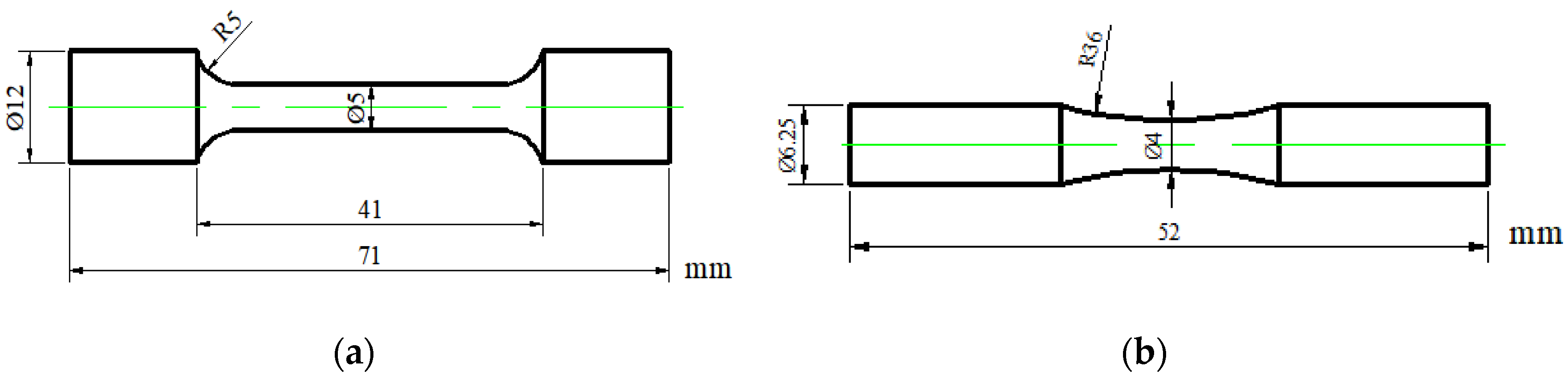
The platers (8 mm × 8 mm × 8 mm) were cut from the heat-treated samples at different temperatures, which were then polished and corroded with 4% alcohol nitric acid solution for 15 s. Afterwards, their microstructures were observed using an optical microscope (OM, LEICA M165C, Barnack, Germany) and a transmission electron microscope (TEM, FEI Tecnai G20, Oregon, USA) operating at 200 kV. An X-ray diffractometer (XRD, Cu Kα radiation, Amsterdam, Holland) was used to identify the metallographic phase of the materials. The hardness of the samples was measured with durometer (SCTMC, HV-50, Shanghai, China), using an applied load and dwelling time of 200 g and 15 s respectively. After being quenched and tempered treatment, the samples were machined into standard specimens for room temperature tensile (Chinese standard, GB/T228-2002) and fatigue tests (Chinese standard, GB/T4337-2015). The tensile tests using a universal testing machine (CMT5105, Shenzhen, China), and the dimension of tensile specimens are shown in Figure 1a. The fatigue tests were assessed using a rotating bending fatigue test machine (QBWP-10000X, Jinan, China), and the dimension of fatigue specimens is shown in Figure 1b. Fatigue strength of 1 × 10⁷ cycles is usually defined as the fatigue limit. All specimens were tested at room temperature at a frequency of 6000 r/min and under load control at stress ratios R = −1, and the regarded load was taken as the control variable [13,14,15]. The dimensions of fatigue specimens are shown in Figure 1b. Fracture surfaces were examined with a scanning electron microscope (NOVA NANOSEM 430, Eindhoven, Holland). Before being examined, the surfaces were cleaned using alcohol for 5 min.
3. Results and Discussion
3.1. Microstructural Characterization
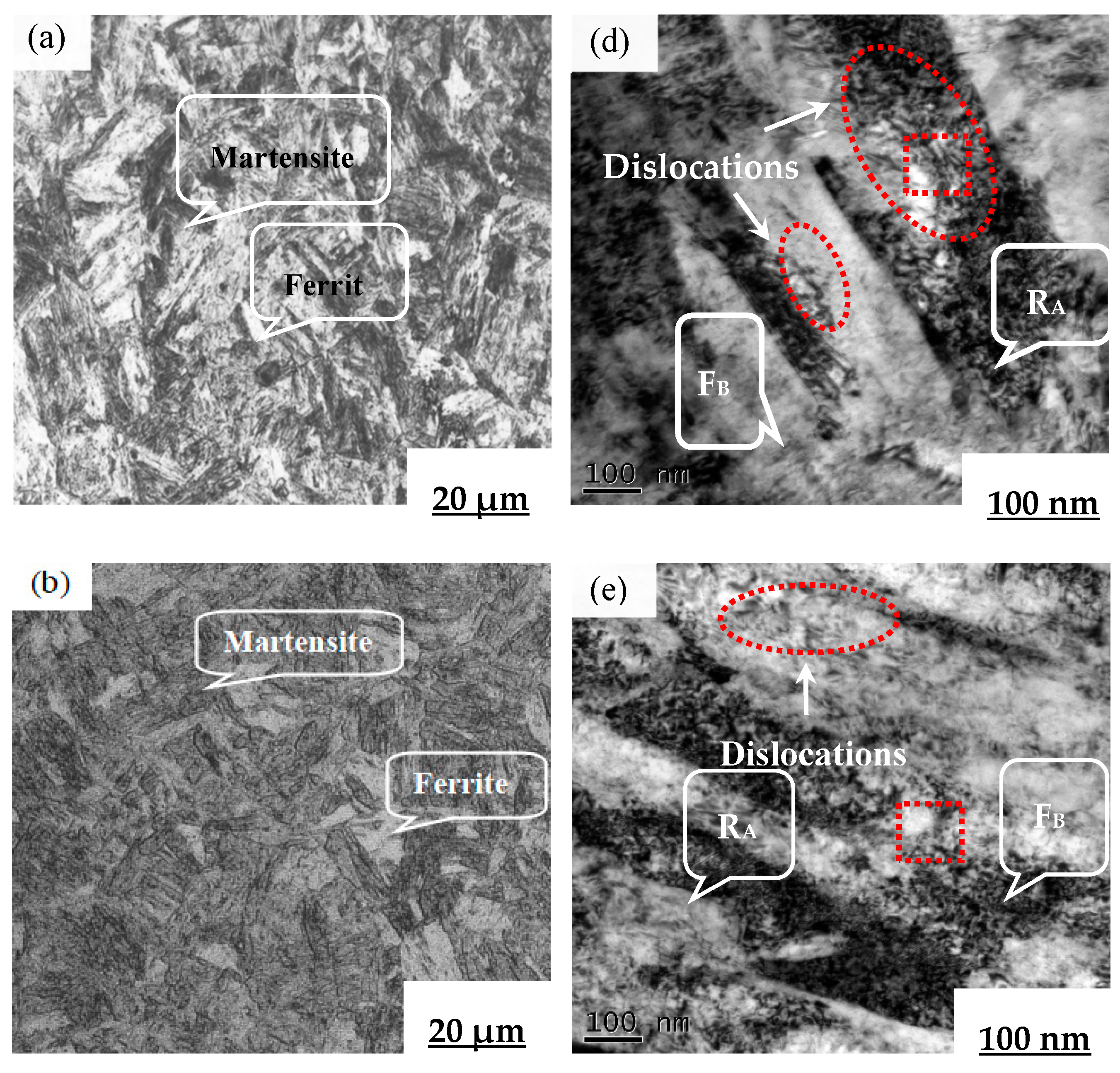
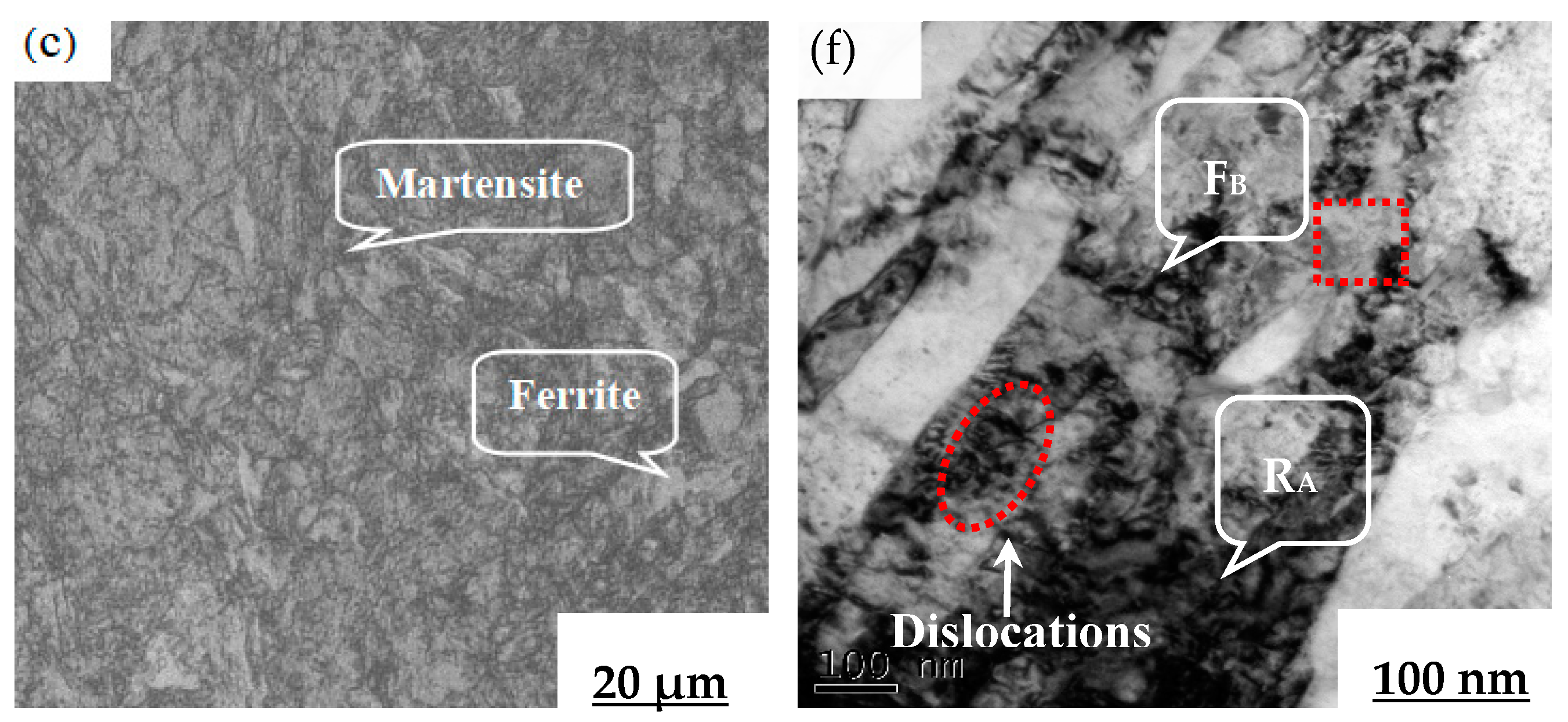
Figure 2a–c shows the microstructural structures of 17Cr2Ni2MoVNb tempered at the temperature of 180, 400 and 620 °C, respectively. The tempering temperature had a great influence on martensitic shape; there were a large number of lath martensites, which were a product of standardized quenching as shown in Figure 2a. Figure 2c shows that after quenching and high temperature tempering, the structure maintained the microstructures, though they were more detailed and fuzzy. Figure 2d–f display the transmission electron microscopy (TEM) microstructures of long and slender ferrite and retained austenite at each tempering temperature. The results reveal that there were much more dislocations, and the areas marked with “1” illustrate the decomposition process of residual austenite. The residual austenite gradually transformed into lower bainite or tempered martensite at each heat treatment condition, and finer bainite were achieved at the temperature of 180 °C; a similar transformation of microstructures was previously reported by Shendy [16].
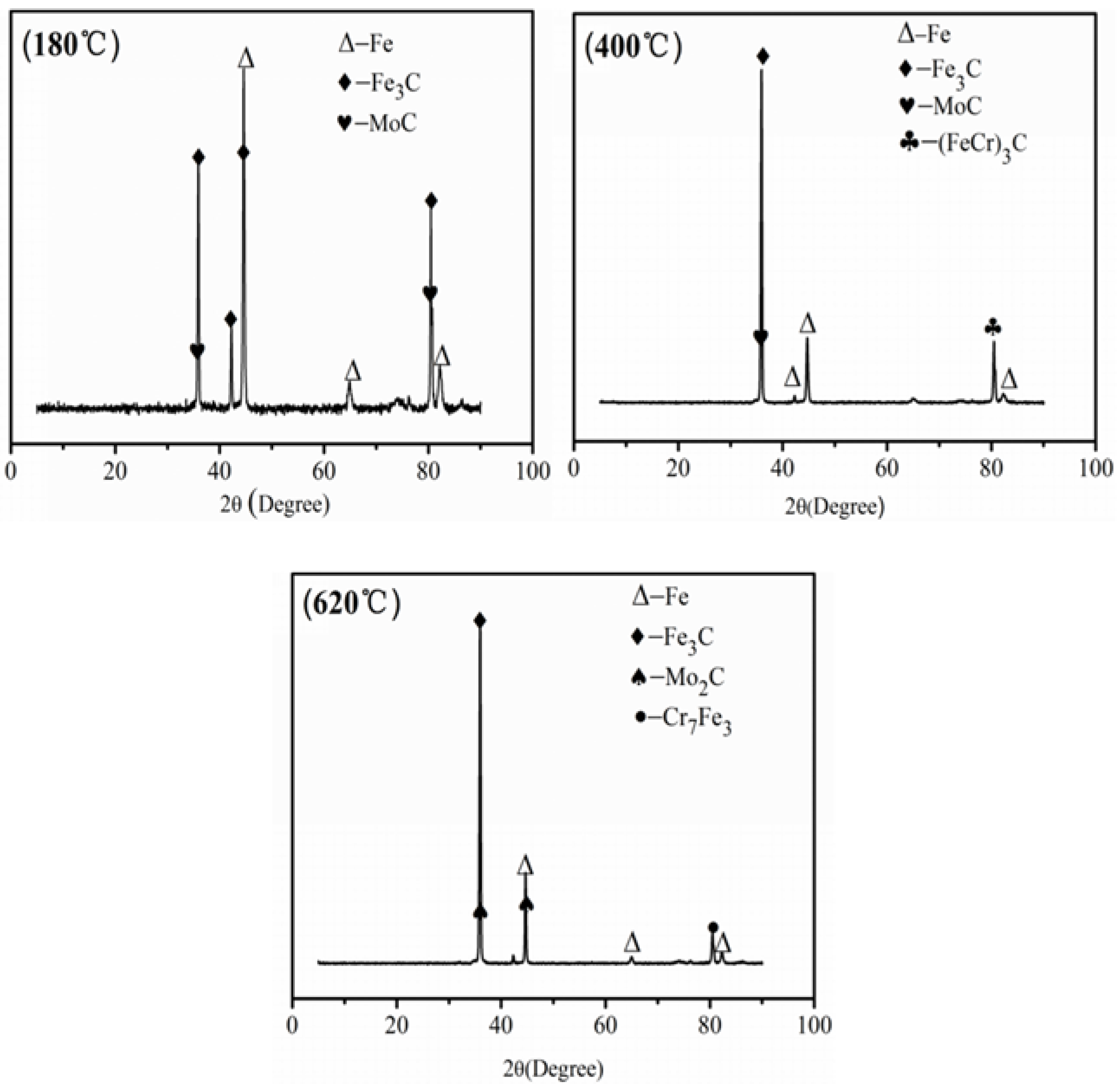
Figure 3 shows the X-ray diffraction (XRD) patterns. The results were similar and indicate that the test conditions were stable and the samples preparation was qualified. The carbides formed at different tempering temperatures were related to the diffusion rate of alloying elements in iron [17]. Different carbides were formed at each heat treatment temperature, such as Fe3C, MoC and Cr7C3. Fe3C was precipitated at a low tempering temperature, the diffusion of Cr to Fe3C exceeded a certain limit, and Cr7Fe3 was formed at the tempering temperature of 400 °C. The tempering temperature continued to rise, thus Cr7C3 and C combined to form (FeCr)3C.
3.2. Hardness
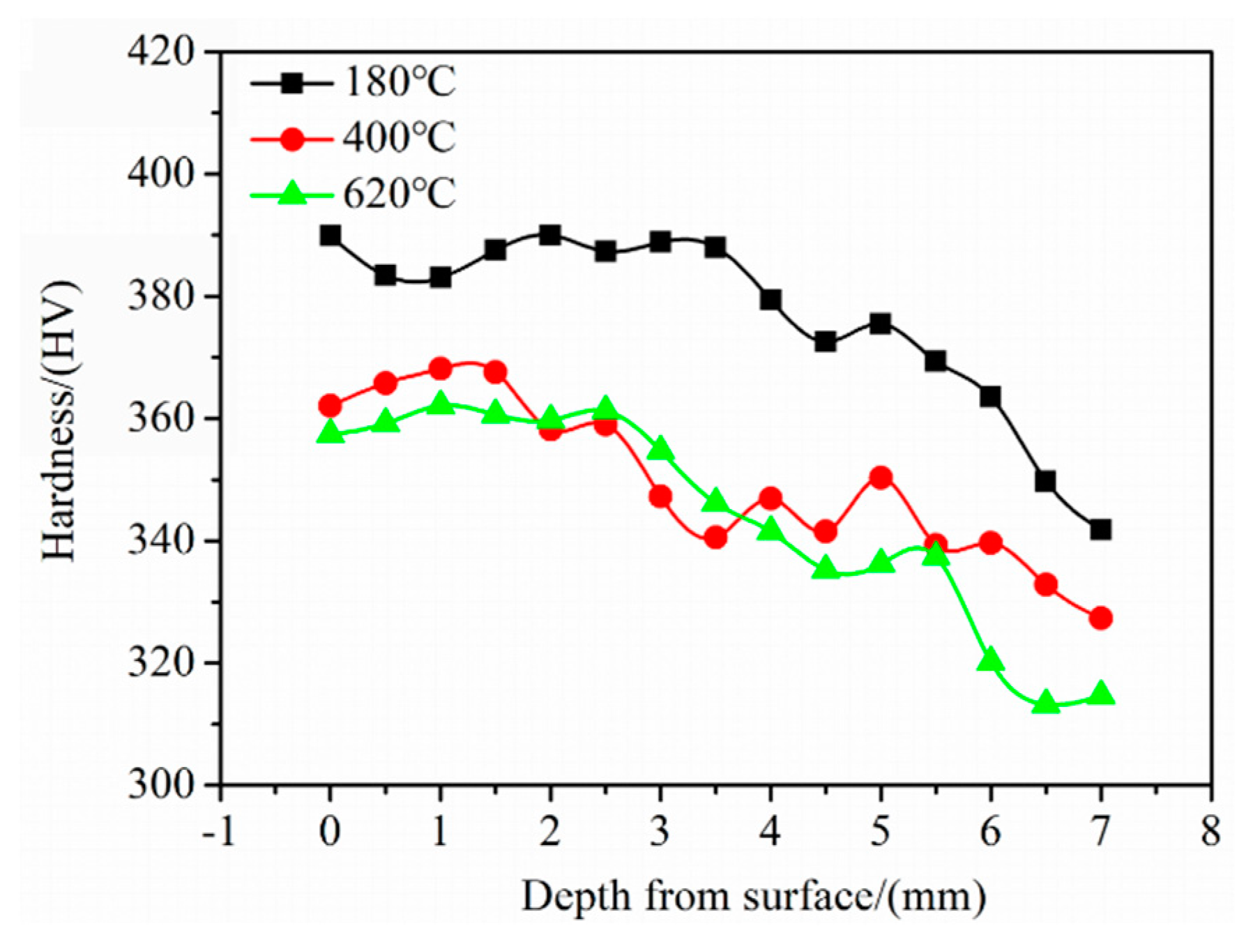
The results of the hardness experiment are shown in Figure 4. The process of tempering involved dissolving the supersaturated solid solution [18,19]. It can be seen that the hardest parts of the samples were the outer edges, and the hardness value of the samples with tempered at 400 °C and 620 °C were not significantly different. For all samples, the hardness at a tempering temperature of 180 °C was significantly higher than that of the other two tempering temperatures, and the highest hardness value was observed at that temperature (HV 389). It is probable that the increased tempering temperature reduced the solid solution strengthening of carbon and the decomposition of alloy elements.
3.3. Tensile Properties
3.3.1. Tensile Strength
It is well known that the effective methods to improve the strength in steel mainly include fine grain strengthening, and precipitation strengthening [20]. The fine grain strengthening is the most effective method of improving the strength. The reason is that the smaller the grain size is, the larger the number of boundaries. The grain size is investigated by the Scherrer equation, as follows:
where is the mean size of crystal, is the dimensionless shape factor, is the X-ray wavelength, is the breadth at half the maximum peak intensity, and is the Bragg angle (in degrees).
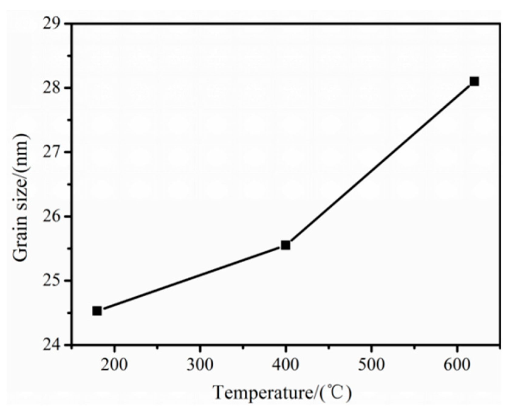
The relationships between the mean size of crystal and the tempering temperature are shown in Figure 5. It should be noted that the higher the tempering temperature, the larger the grain size: at tempering temperatures of 180, 400, and 620 °C, the mean grain sizes are approximately 24.53, 25.55 and 28.10 nm, respectively. Moreover, alloying carbides improve precipitation strengthening, while increased tempering temperature reduces the strengthening effect. The samples, tempered at 180 °C have the most alloying carbides. Therefore, samples at 180 °C have the best precipitation strengthening effect.
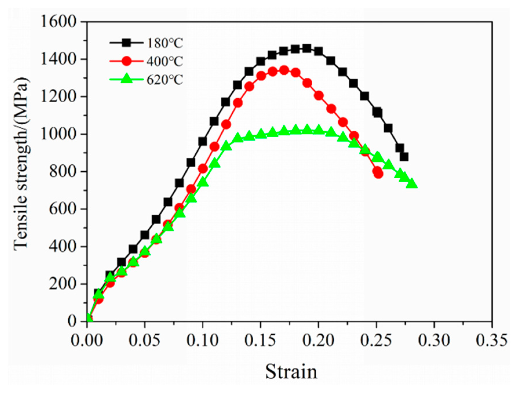
Figure 6 shows the stress-strain curves at room temperature for samples tempered at different tempering temperatures. The samples tempered at 620 °C exhibited the lowest tensile strength, which was 1019 MPa, due partly to Cr inhibiting the precipitation of Fe3C and the retardation of martensite decomposition, and also in part due to the alloy carbide precipitates and the saturation of C decreasing at a high tempering temperature. Data presented of tensile properties, including 2% yield strength (2% YS), ultimate tensile strength (UTS) and elongation (EL), are the average of three experimental results; the tensile properties of 17Cr2Ni2MoVNb steel are listed in Table 3.
3.3.2. Fracture Analysis
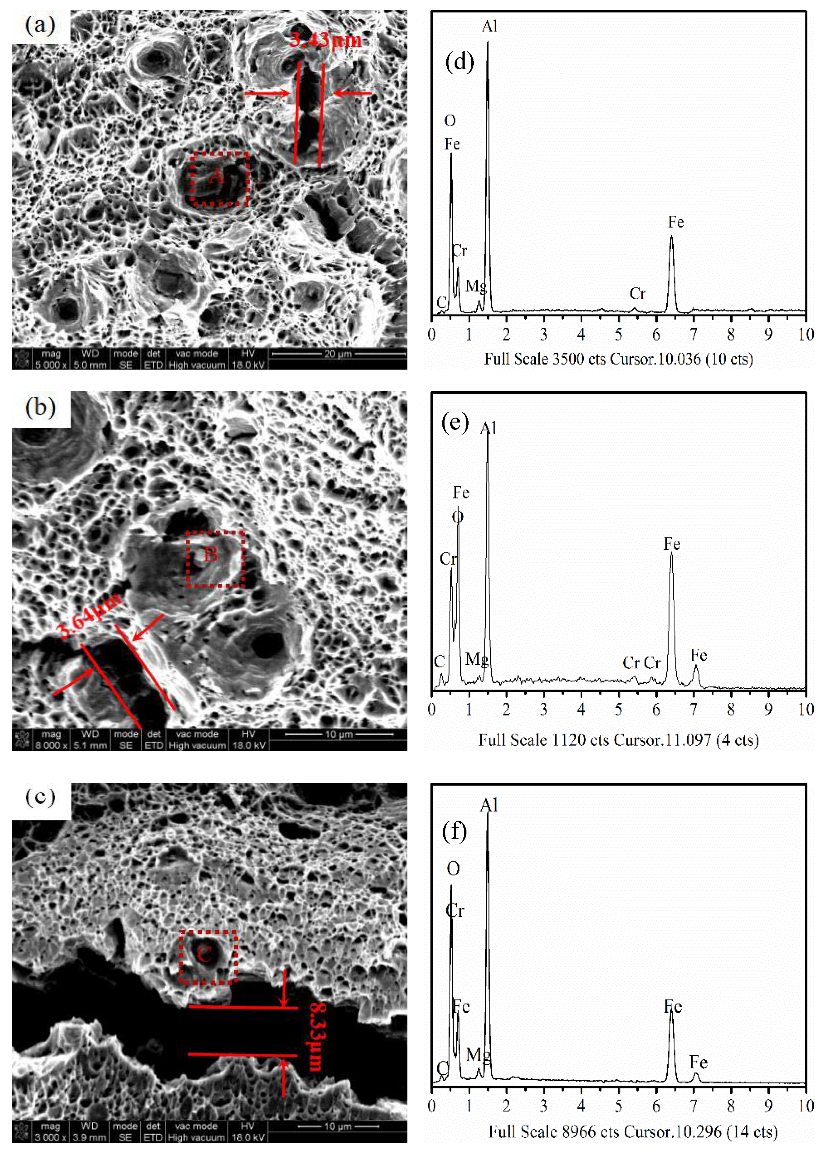
Figure 7a–c shows the SEM micrographs of cracks. There were a large number of tearing ridges and dimples on the fracture surface, indicating that the tensile fracture mode was a ductile fracture. In addition, the hardness of (FeCr)3C and Cr7C3 was higher than that of Fe3C, which was more likely to bring uneven slip or microcracks in the surrounding. Due to the different slip coefficients of the crystal grains in different directions, the slip could not be extended over one direction and the displacement of the crystal grains was accumulated at the front of the grain boundary, resulting in high stress concentration and subsequently leaving a tortuous area of deformation on the specimen surface [21,22]. It should be noted that the largest size of crack of samples was measured about 3.43, 3.64, 8.33 μm achieved with the tempering temperatures of 180, 400, and 620 °C, respectively.
Figure 7d–f shows the energy dispersive X-ray analysis (EDS) patterns of oxides, and the chemical compositions are listed in Table 4. The samples, tempering at 620 °C, contained approximately 33.45 wt % O. This indicates that the higher the content of O elements and the more oxides a sample has, the more cracks there will be. This is in good agreement with Wang [23], so it can be concluded that the mismatch between oxides and the base metal of the elastic modulus may be one mechanism that generated the microcracks.
3.4. Fatigue Characteristics
3.4.1. S-N Curve
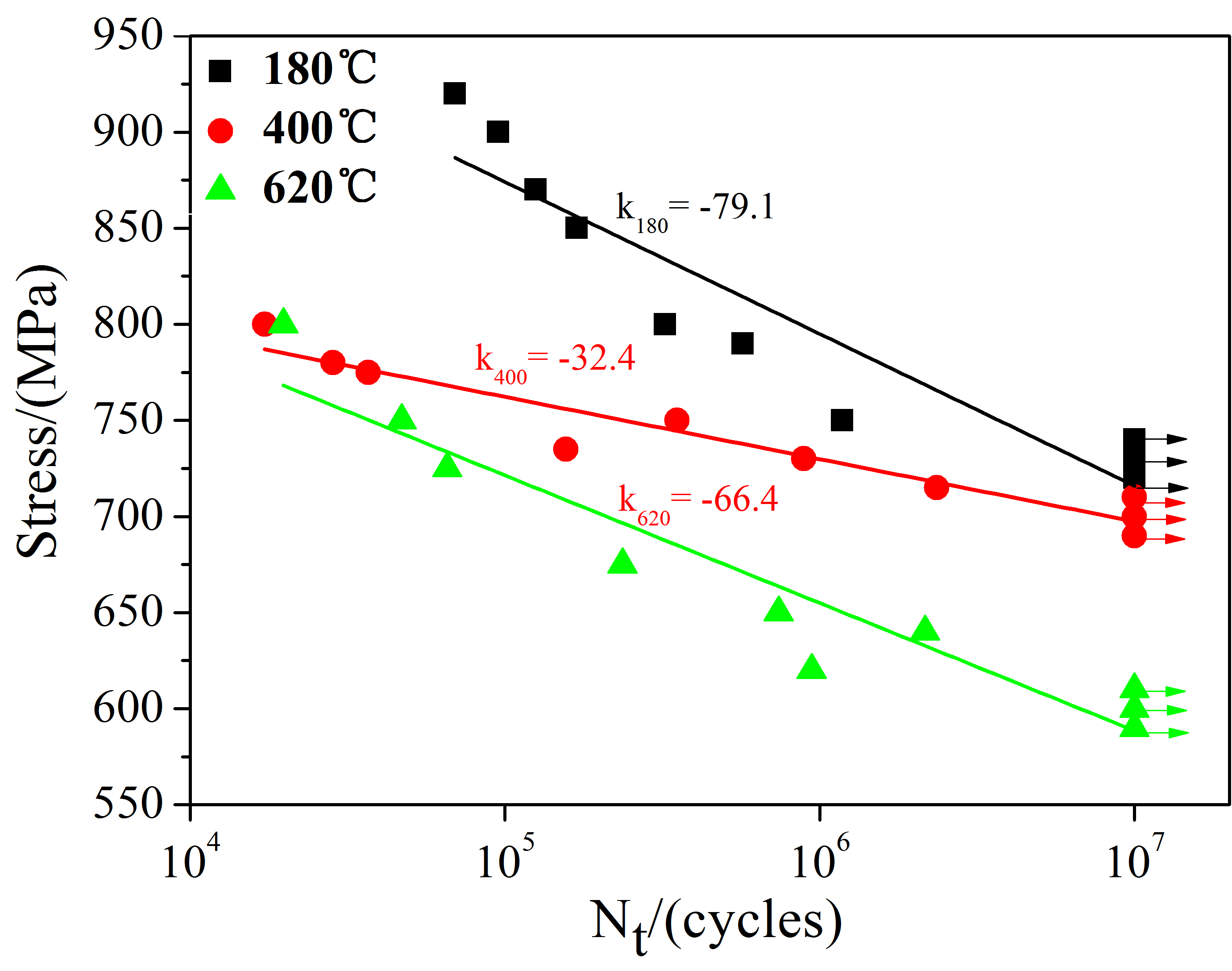
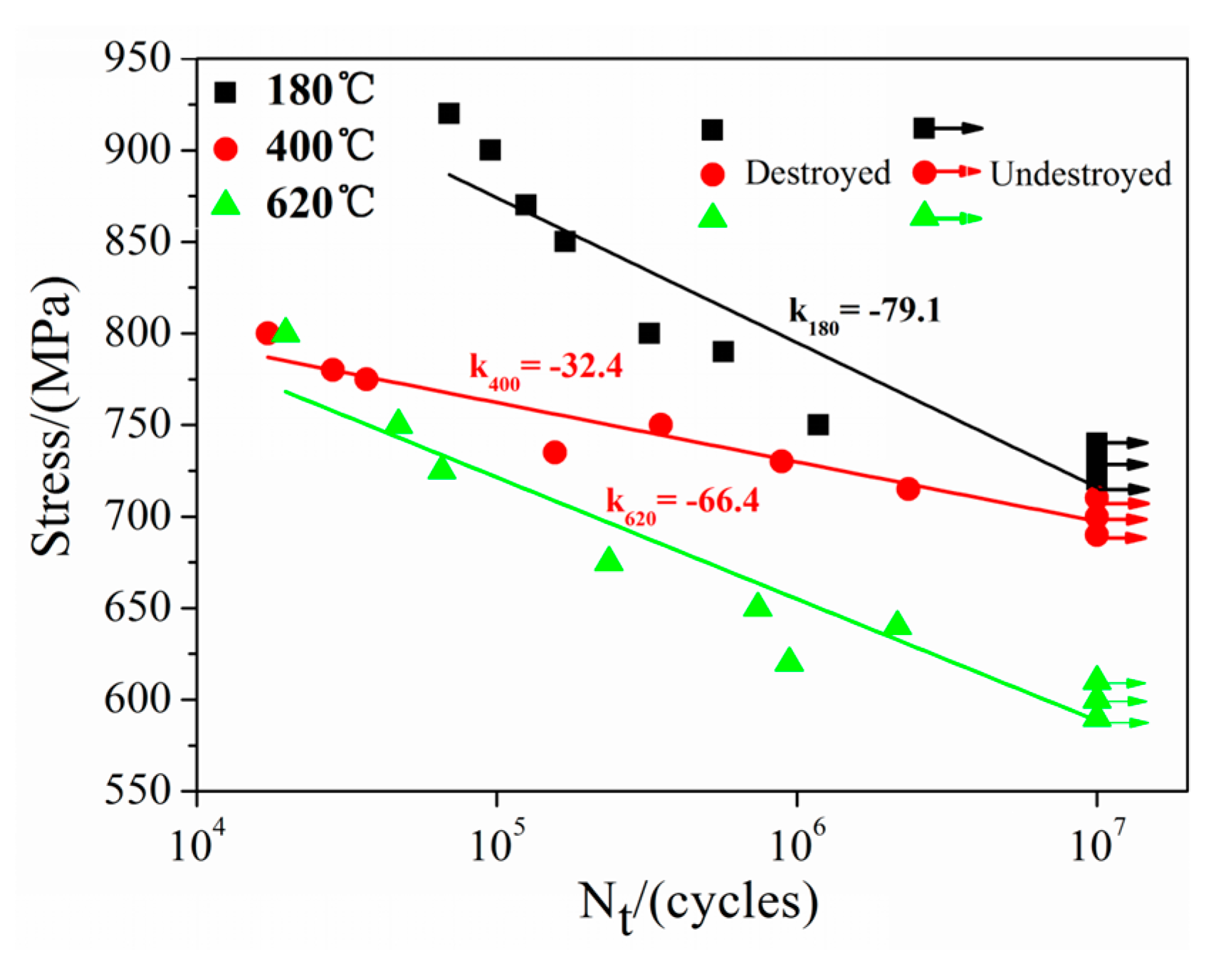
The S-N curves of the samples with different tempering temperatures are shown in Figure 8. The arrows indicate the unbroken specimens in the fatigue tests. The most interesting finding of S-N curves was that the fatigue life increased when cyclic stress declined, with the S-N curves showing a general trend of this material. The fatigue strength limits at 107 cycles of the three specimens were about 730, 700 and 600 MPa, obtained at the standard limit for the samples with the tempering temperatures of 180, 400 and 620 °C, respectively. It should be noted that the dislocation was an important factor effecting the fatigue strength limits and high-density dislocations contributed to the improvement in fatigue strength [24]. With the tempering temperature rising, the stacking of dislocations coalesces, and this resulted in a decreasing dislocations density. Therefore, the samples tempered at 180 °C were logical to get the highest fatigue strength limits.
3.4.2. Fractography
Figure 9 reveals the SEM micrographs of the wear zone. The local plastic strain accumulated during the loading times, and the micro strain gradient increased, producing the redistribution of micro strain in the samples. The repeated opening and closing of the crack propagation region caused friction in the fatigue test process, illustrated in the formation of river patterns on the fracture surface. After the initiation of cracks, wear occurred between the two parts on the fracture surface, and there were scars and wear debris in this zone. The arrows indicate the direction of fatigue cracks propagation, which are evidence of fatigue rupture characteristics. These debris between the contact surfaces remained and agglomerated as moving particles, plowing the surfaces to generate abrasive pits. Hardness of 17Cr2Ni2MoVNb steel markedly reduced when the tempering temperature increased; the debris was gradually worn out before disappearing due to friction. Thus, there was no obvious debris on the surface of the samples with tempering temperature of 620 °C.
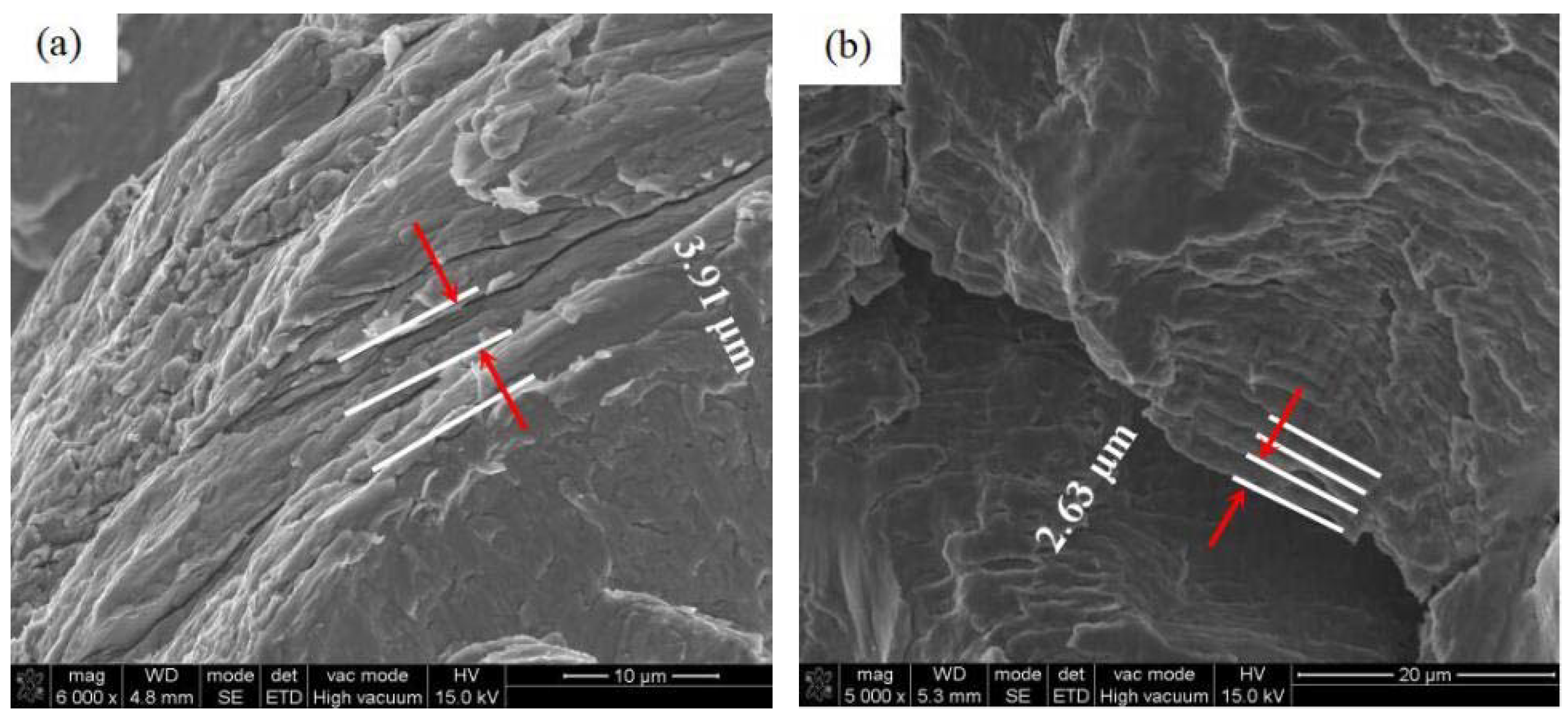
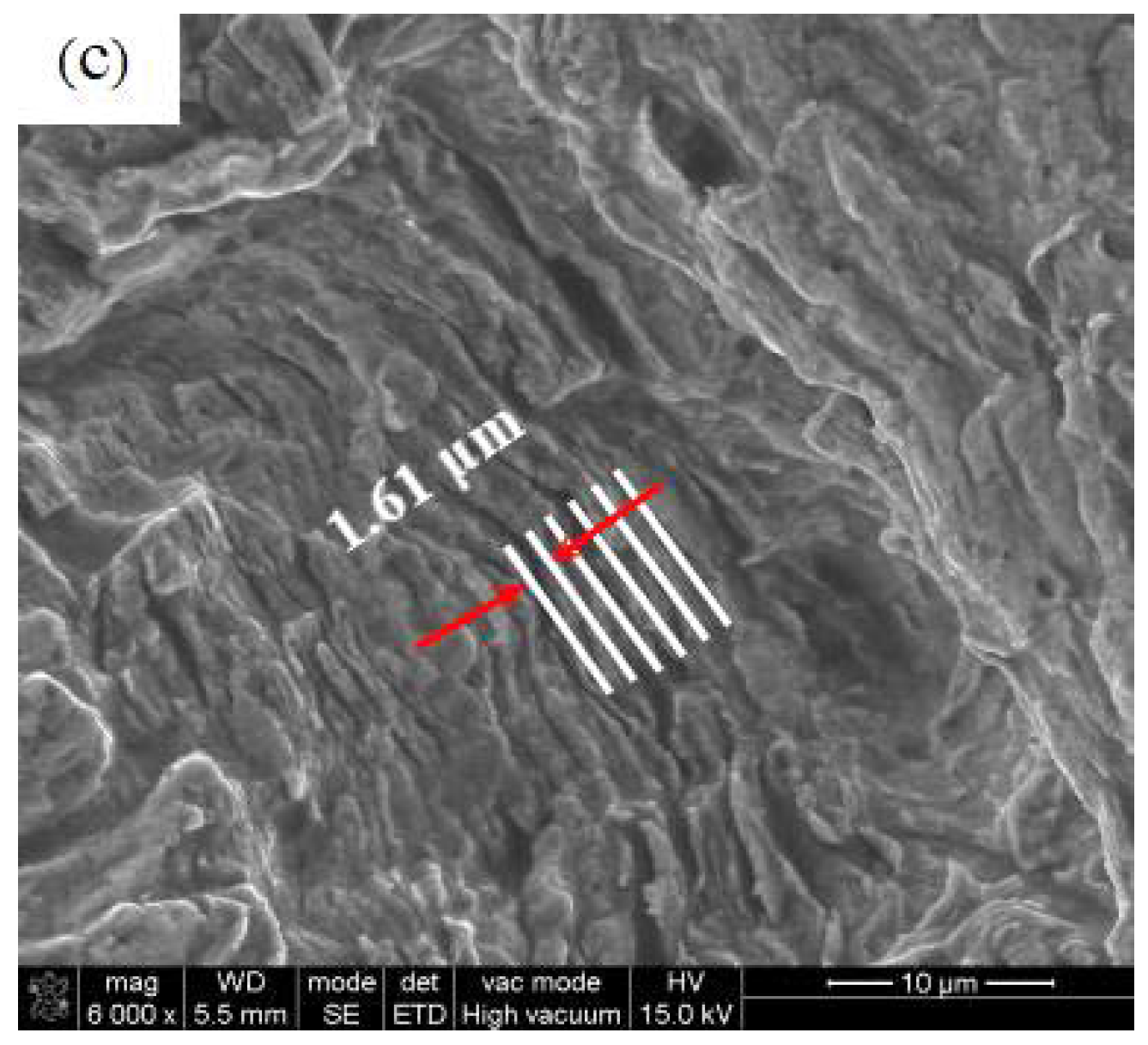
Fatigue consists of the cracks initiation zone, crack propagation zone, and the final fatigue zone. All the cracks are prone to initiate at or near the specimen surface because the cyclic plastic deformation at or near the surface acquires the maximum cyclic stress compared to that of internal regions [25]. Figure 10 displays the typical SEM micrographs of the ridges produced by the strong deformation at the samples surfaces. Cracks and slip lines were distributed on the ridges surfaces: the furthest distances of slip lines within samples were measured about 3.91, 2.63, 1.61 μm achieved with the tempering temperatures of 180, 400, and 620 °C, respectively. Samples at the tempering temperature of 180 °C had the fewest number of cracks on the ridges because it had the highest strength among the samples. This was consistent with Neumann [26], who proposed a slip model of fatigue cracked, and confirmed that cracks growths were caused by the expansion of the slip lines.
4. Conclusions
The increased tempering temperature reduced the dislocations density, improved the detail of the microstructures, and the residual austenite gradually transformed into lower bainite or tempered martensite.
The tensile strengths were 1456, 1341 and 1019 MPa with the tempering temperatures of 180, 400 and 620 °C respectively. The size of cracks increased when the tempering temperature decreased, with the largest crack size of 8.33 μm appearing at the tempering temperature of 620 °C.
The fatigue strength limits decreased with an increase of the tempering temperature. Fatigue strength limits were measured about 730, 700 and 600 MPa, obtained with tempering temperatures of 180, 400, and 620 °C, respectively. The distance of slip lines decreased when the tempering temperature rose; the furthest distance of slip lines at the tempering temperature of 180 °C was about 3.91 μm.
Author Contributions
Both authors contributed equally to the work.
Funding
This research received no external funding.
Acknowledgments
The authors would like to thank the National Engineering Research Center of Near-Net-Shape Forming for Metallic Materials, State Key Laboratory of Smart Manufacturing for Special Vehicle as well as Transmission System and State Key Laboratory of Internal Combustion Engine Reliability for material preparation and mechanical properties testing.
Conflicts of Interest
The authors declare no conflict of interest.
References
- Yang, Y.H.; Wang, M.Q.; Chen, J.C.; Dong, H. Microstructure and mechanical properties of gear steels after high temperature carburization. J. Iron Steel Res. Int. 2013, 20, 140–145. [Google Scholar] [CrossRef]
- Gurudas, M.; Kumar, T.N.; Kumar, G.S. Enhancement of mechanical properties in bainitic steel processed from different austenitization temperatures. Steel Res. Int. 2017, 2, 87–92. [Google Scholar]
- Morave, J.M.; Mantovani, D. Biodegradable metals for cardiovascular stent application: Interests and new opportunities. Int. J. Mol. Sci. 2011, 12, 4250–4270. [Google Scholar] [CrossRef] [PubMed]
- Schinhammer, M.; Hänzi, A.; Löffle, J.; Uggowitzer, P.J. Design strategy for biodegradable Fe-based alloys for medical applications. Acta Biomater. 2010, 6, 1705–1713. [Google Scholar] [CrossRef] [PubMed]
- Francis, A.; Yang, Y.; Virtanen, S.; BoccacciniIron, A.R. Iron and iron-based alloys for temporary cardiovascular applications. J. Mater. Sci. Mater. Med. 2015, 26, 138–154. [Google Scholar] [CrossRef] [PubMed]
- Pereloma, E.V.; Scott, R.I.; Smith, R.M. Effect of Cr on strain ageing behaviour of low carbon steel. Mater. Sci. 2007, 24, 539–543. [Google Scholar]
- Yang, Z.; Cong, D.Y.; Sun, X.M.; Nie, Z.H.; Wang, Y.D. Enhanced cyclability of elastocaloric effect in boron-microalloyed NiMn-In magnetic shape memory alloys. Acta Mater. 2017, 127, 33–42. [Google Scholar] [CrossRef]
- Wang, Q.W.; Li, C.S.; Chen, J.; Tu, X.Y. Effects of heat input on microstructure and mechanical properties of Fe-2Cr-Mo-0.12C steel. Mater. Sci. Technol. 2018, 34, 538–546. [Google Scholar] [CrossRef]
- Wang, M.Q.; Jie, S.; Han, D. Microstructure and mechanical properties of V-Nb microalloyed steel for heavy-duty gear. Trans. Mater. 2007, 28, 18–23. (In Chinese) [Google Scholar]
- Xiao, F.R.; Cao, Y.B.; Qiao, G.Y.; Zhang, X.B.; Bo, L. Effect of Nb solute and NbC precipitates on dynamic or static recrystallization in Nb steels. J. Iron Steel Res. Int. 2012, 19, 52–56. [Google Scholar] [CrossRef]
- Chen, S.L.; Geng, K. Effect of heat treatment on mechanical properties of Cr-Ni-Mo carburized gear steel. Spec. Steel 2002, 23, 20–22. (In Chinese) [Google Scholar]
- Wu, D.; Wang, F.M.; Cheng, J.; Li, C.R. Effects of Nb and tempering time on carbide precipitation behavior and mechanical properties of Cr-Mo-V Steel for brake discs. Steel Res. Int. 2018, 89. [Google Scholar] [CrossRef]
- Hong, Y.S.; Lei, Z.Q.; Sun, C.Q.; Zhao, A.G. Propensities of crack interior initiation and early growth for very-high-cycle fatigue of high strength steels. Int. J. Fatigue 2014, 58, 144–152. [Google Scholar] [CrossRef]
- Laasraoui, A.; Jonas, J.J. Prediction of steel flow stresses at high temperatures and strain rates. Metall. Trans. A 1991, 7, 1545–1558. [Google Scholar] [CrossRef]
- Mohammad, J.K.; Mohammad, A. Evaluation of high-cycle bending fatigue and fracture behaviors in EN-GJS700-2 ductile cast iron of crankshafts. Eng. Fail. Anal. 2018, 85, 189–200. [Google Scholar]
- Shendy, B.R.; Yoozbashi, M.N.; Avishan, B.; Yazdani, S. An investigation on rotating bending fatigue behavior of nanostructured low-temperature bainitic steel. Acta Metall. 2014, 27, 233–238. [Google Scholar] [CrossRef]
- Swarr, T.; Krauss, G. The effect of structure on the deformation of as-quenched and tempered martensite in a Fe-0.2 pct C alloy. Metall. Trans. A 1976, 7, 41–48. [Google Scholar] [CrossRef]
- Tomita, Y.; Okabayashi, K. Effect of microstructure on strength and toughness of heat-treated low alloy structural steels. Matall. Trans. A 1986, 17, 1203–1207. [Google Scholar] [CrossRef]
- Stasko, R.; Adrian, H.; Adrian, A. Effect of nitrogen and vanadium on austenite grain groeth of a low alloy steel. Mater. Charact. 2006, 5, 340–347. [Google Scholar] [CrossRef]
- Long, S.L.; Liang, Y.L.; Jiang, Y.; Liang, Y.; Yang, M. Effect of quenching temperature on martensite multi-level microstructures and properties of strengh and toughness in 20CrNi2Mo steel. Mater. Sci. Eng. A 2016, 676, 38–47. [Google Scholar] [CrossRef]
- Morito, S.; Tanaka, H.; Konishi, R.; Furuhara, T.; Maki, T. The morphology and crystallography of lath martensite in Fe-C. Acta Mater. 2003, 51, 1789–1799. [Google Scholar] [CrossRef]
- Chang, Y.L.; Chen, P.Y.; Tsai, Y.T.; Yang, J.R. Crystallographic analysis of lenticular martensite in Fe-1.0C-17Cr stainless steel by electron backscatter diffraction. Mater. Charact. 2016, 113, 17–25. [Google Scholar] [CrossRef]
- Wang, C.F.; Wang, M.Q.; Dong, H. In-situ observation of deformation and fracture process for lath martensite steel. J. Iron Steel Res. 2012, 24, 38–43. (In Chinese) [Google Scholar]
- Li, Y.Q. Microstructure and strain fatigue dislocation structure of 7075 RRA Aluminum alloy. Rare Met. 2001, 20, 52–57. [Google Scholar]
- Phung, N.L.; Favier, V.; Ranc, N.; Valès, F.; Mughrabi, H. Very high cycle fatigue of copper: Evolution, morphology and locations of surface slip markings. Int. J. Fatigue 2014, 3, 63–68. [Google Scholar] [CrossRef] [Green Version]
- Neumann, P. Coarse slip model of fatigue. Acta Metall. 1969, 17, 1219–1225. [Google Scholar] [CrossRef]
Figure 1.
Dimensions of the specimens for tensile tests and rotary bending fatigue tests: (a) specimen of tensile tests; (b) specimen of rotary bending fatigue tests.
Figure 1.
Dimensions of the specimens for tensile tests and rotary bending fatigue tests: (a) specimen of tensile tests; (b) specimen of rotary bending fatigue tests.

Figure 2.
Optical microscopy (OM) micrographs of 17Cr2Ni2MoVNb steel tempered at different temperatures of (a) 180 °C, (b) 400 °C, (c) 620 °C and transmission electron microscopy (TEM) micrographs of (d) 180 °C, (e) 400 °C, (f) 620 °C.
Figure 2.
Optical microscopy (OM) micrographs of 17Cr2Ni2MoVNb steel tempered at different temperatures of (a) 180 °C, (b) 400 °C, (c) 620 °C and transmission electron microscopy (TEM) micrographs of (d) 180 °C, (e) 400 °C, (f) 620 °C.


Figure 3.
X-ray diffraction (XRD) patterns of 17Cr2Ni2MoVNb steel tempered at different temperatures.
Figure 3.
X-ray diffraction (XRD) patterns of 17Cr2Ni2MoVNb steel tempered at different temperatures.

Figure 4.
Hardness of 17Cr2Ni2MoVNb steel tempered at different temperatures.

Figure 5.
The relationships between the mean size of crystal and tempering temperature.

Figure 6.
Tensile properties of 17Cr2Ni2MoVNb steel tempered at different temperatures.

Figure 7.
Typical SEM micrographs of cracks at different temperatures of (a) 180 °C, (b) 400 °C, (c) 620 °C and EDS graphs of oxides at different temperatures of (d) 180 °C, (e) 400 °C, (f) 620 °C.
Figure 7.
Typical SEM micrographs of cracks at different temperatures of (a) 180 °C, (b) 400 °C, (c) 620 °C and EDS graphs of oxides at different temperatures of (d) 180 °C, (e) 400 °C, (f) 620 °C.

Figure 8.
S-N curve of 17Cr2Ni2MoVNb steel tempered at different temperatures.

Figure 9.
Micrographs of wear zone: (a) tempered at 180 °C maximum stress 900 MPa and 95,257 cycles to failure; (b) tempered at 400 °C, maximum stress 750 MPa and 352,388 cycles to failure; (c) tempered at 620 °C, maximum stress 750 MPa and 46,005 cycles to failure.
Figure 9.
Micrographs of wear zone: (a) tempered at 180 °C maximum stress 900 MPa and 95,257 cycles to failure; (b) tempered at 400 °C, maximum stress 750 MPa and 352,388 cycles to failure; (c) tempered at 620 °C, maximum stress 750 MPa and 46,005 cycles to failure.
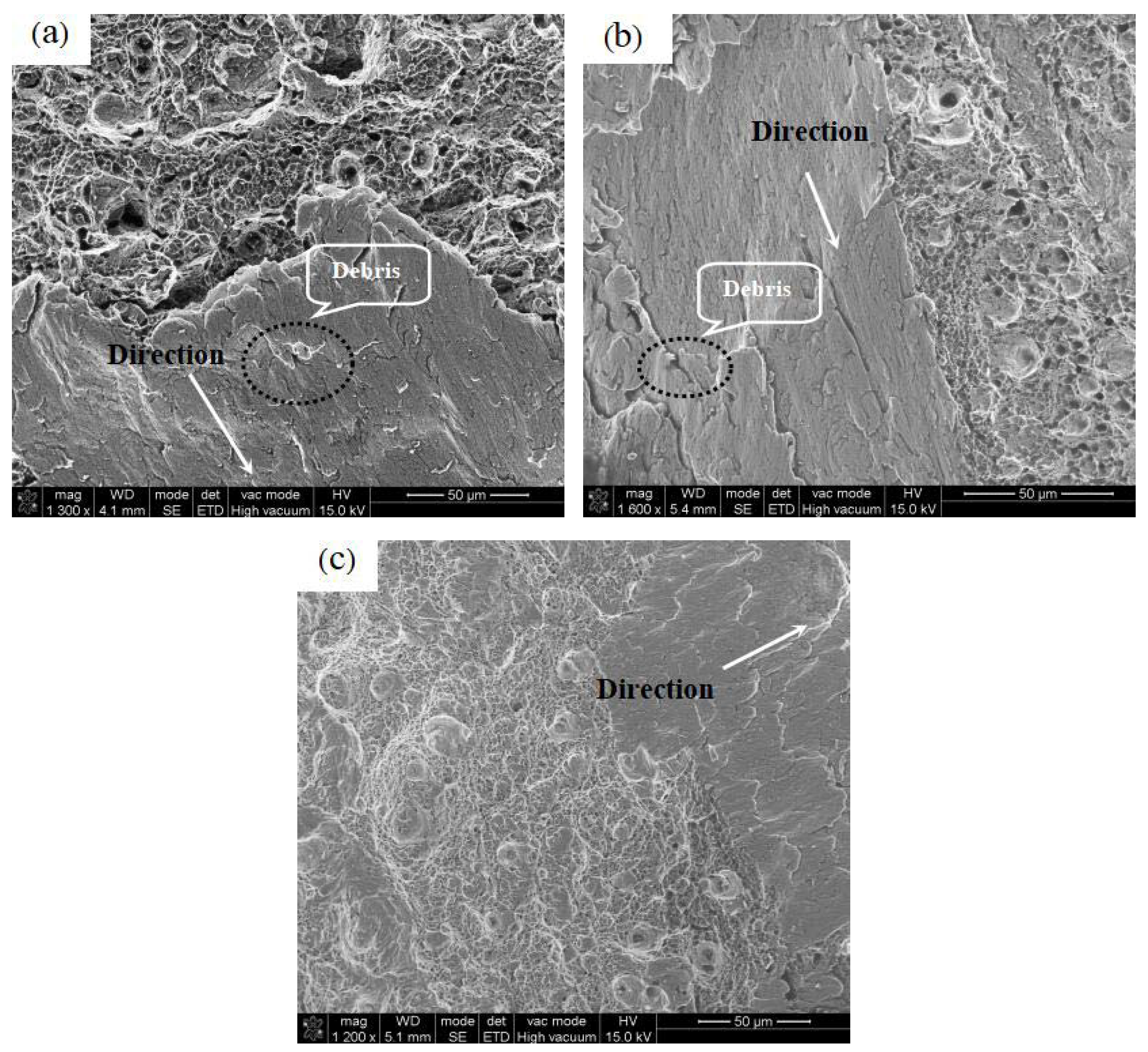
Figure 10.
Micrographs of the ridges: (a) tempered at 180 °C maximum stress 900 MPa and 95,257 cycles to failure; (b) tempered at 400 °C, maximum stress 750 MPa and 352,388 cycles to failure; (c) tempered at 620 °C, maximum stress 750 MPa and 46,005 cycles to failure.
Figure 10.
Micrographs of the ridges: (a) tempered at 180 °C maximum stress 900 MPa and 95,257 cycles to failure; (b) tempered at 400 °C, maximum stress 750 MPa and 352,388 cycles to failure; (c) tempered at 620 °C, maximum stress 750 MPa and 46,005 cycles to failure.


Table 1.
Chemical compositions of 17Cr2Ni2MoVNb steel (wt %).
| C | Si | Mn | Cr | Ni | Al | Cu | Mo | V | Nb | Mg | S | P |
|---|---|---|---|---|---|---|---|---|---|---|---|---|
| 0.188 | 0.015 | 0.40 | 1.83 | 1.63 | 0.048 | 0.01 | 0.31 | 0.093 | 0.059 | 0.007 | 0.001 | 0.009 |
Table 2.
Heat treatment of 17Cr2Ni2MoVNb steel.
| Samples Label | Quenching Temperature | Quenching Method | Tempering Temperature | Tempering Method |
|---|---|---|---|---|
| 1 | 860 °C × 1 h | oil | 180 °C × 2 h | water |
| 2 | 860 °C × 1 h | oil | 400 °C × 2 h | water |
| 3 | 860 °C × 1 h | oil | 620 °C × 2 h | water |
Table 3.
Mechanical properties of 17Cr2Ni2MoVNb steel.
| Sample Label | Temperature (°C) | 2% YS (MPa) | UTS (MPa) | EL (%) |
|---|---|---|---|---|
| 1 | 180 | 1362 | 1456 | 13.76 |
| 2 | 400 | 1288 | 1341 | 12.48 |
| 3 | 620 | 964 | 1019 | 14.8 |
Table 4.
Content of oxides.
| Element | Weight % | ||
|---|---|---|---|
| A | B | C | |
| C | 7.81 | 4.99 | 2.41 |
| O | 19.23 | 32.54 | 33.45 |
| Mg | 0.63 | 1.15 | 1.21 |
| Al | 21.2 | 24.66 | 25.34 |
| Cr | 1 | 1.47 | 1.62 |
| Fe | 50.13 | 35.19 | 35.97 |
© 2018 by the authors. Licensee MDPI, Basel, Switzerland. This article is an open access article distributed under the terms and conditions of the Creative Commons Attribution (CC BY) license (http://creativecommons.org/licenses/by/4.0/).
Share and Cite
MDPI and ACS Style
Qu, S.-G.; Zhang, Y.-L.; Lai, F.-Q.; Li, X.-Q. Effect of Tempering Temperatures on Tensile Properties and Rotary Bending Fatigue Behaviors of 17Cr2Ni2MoVNb Steel. Metals 2018, 8, 507. https://doi.org/10.3390/met8070507
AMA Style
Qu S-G, Zhang Y-L, Lai F-Q, Li X-Q. Effect of Tempering Temperatures on Tensile Properties and Rotary Bending Fatigue Behaviors of 17Cr2Ni2MoVNb Steel. Metals. 2018; 8(7):507. https://doi.org/10.3390/met8070507
Chicago/Turabian StyleQu, Sheng-Guan, Ya-Long Zhang, Fu-Qiang Lai, and Xiao-Qiang Li. 2018. "Effect of Tempering Temperatures on Tensile Properties and Rotary Bending Fatigue Behaviors of 17Cr2Ni2MoVNb Steel" Metals 8, no. 7: 507. https://doi.org/10.3390/met8070507
Note that from the first issue of 2016, this journal uses article numbers instead of page numbers. See further details here.